EP1297983B1 - Kraftfahrzeugabgasanlage mit inertialer Schwingungsdämpfungsmasse - Google Patents
Kraftfahrzeugabgasanlage mit inertialer Schwingungsdämpfungsmasse Download PDFInfo
- Publication number
- EP1297983B1 EP1297983B1 EP20020292251 EP02292251A EP1297983B1 EP 1297983 B1 EP1297983 B1 EP 1297983B1 EP 20020292251 EP20020292251 EP 20020292251 EP 02292251 A EP02292251 A EP 02292251A EP 1297983 B1 EP1297983 B1 EP 1297983B1
- Authority
- EP
- European Patent Office
- Prior art keywords
- exhaust
- support
- damper
- suspension
- flange
- Prior art date
- Legal status (The legal status is an assumption and is not a legal conclusion. Google has not performed a legal analysis and makes no representation as to the accuracy of the status listed.)
- Expired - Lifetime
Links
Images
Classifications
-
- F—MECHANICAL ENGINEERING; LIGHTING; HEATING; WEAPONS; BLASTING
- F01—MACHINES OR ENGINES IN GENERAL; ENGINE PLANTS IN GENERAL; STEAM ENGINES
- F01N—GAS-FLOW SILENCERS OR EXHAUST APPARATUS FOR MACHINES OR ENGINES IN GENERAL; GAS-FLOW SILENCERS OR EXHAUST APPARATUS FOR INTERNAL-COMBUSTION ENGINES
- F01N13/00—Exhaust or silencing apparatus characterised by constructional features
- F01N13/18—Construction facilitating manufacture, assembly, or disassembly
- F01N13/1805—Fixing exhaust manifolds, exhaust pipes or pipe sections to each other, to engine or to vehicle body
- F01N13/1811—Fixing exhaust manifolds, exhaust pipes or pipe sections to each other, to engine or to vehicle body with means permitting relative movement, e.g. compensation of thermal expansion or vibration
- F01N13/1822—Fixing exhaust manifolds, exhaust pipes or pipe sections to each other, to engine or to vehicle body with means permitting relative movement, e.g. compensation of thermal expansion or vibration for fixing exhaust pipes or devices to vehicle body
-
- B—PERFORMING OPERATIONS; TRANSPORTING
- B60—VEHICLES IN GENERAL
- B60K—ARRANGEMENT OR MOUNTING OF PROPULSION UNITS OR OF TRANSMISSIONS IN VEHICLES; ARRANGEMENT OR MOUNTING OF PLURAL DIVERSE PRIME-MOVERS IN VEHICLES; AUXILIARY DRIVES FOR VEHICLES; INSTRUMENTATION OR DASHBOARDS FOR VEHICLES; ARRANGEMENTS IN CONNECTION WITH COOLING, AIR INTAKE, GAS EXHAUST OR FUEL SUPPLY OF PROPULSION UNITS IN VEHICLES
- B60K13/00—Arrangement in connection with combustion air intake or gas exhaust of propulsion units
- B60K13/04—Arrangement in connection with combustion air intake or gas exhaust of propulsion units concerning exhaust
-
- F—MECHANICAL ENGINEERING; LIGHTING; HEATING; WEAPONS; BLASTING
- F16—ENGINEERING ELEMENTS AND UNITS; GENERAL MEASURES FOR PRODUCING AND MAINTAINING EFFECTIVE FUNCTIONING OF MACHINES OR INSTALLATIONS; THERMAL INSULATION IN GENERAL
- F16F—SPRINGS; SHOCK-ABSORBERS; MEANS FOR DAMPING VIBRATION
- F16F7/00—Vibration-dampers; Shock-absorbers
- F16F7/10—Vibration-dampers; Shock-absorbers using inertia effect
- F16F7/104—Vibration-dampers; Shock-absorbers using inertia effect the inertia member being resiliently mounted
Definitions
- the present invention relates to a vehicle exhaust line automobile according to the preamble of claim 1, as known from FR-A-2761730 (a flexible ring also serves as a bator).
- An exhaust line usually comprises a pipe exhaust system, an exhaust support attached to the exhaust pipe, and suspension and filtration means mounted between the exhaust support and the vehicle body.
- the means of suspension and filtration normally comprise a elastic stud with two frames for fixing on the one hand to the support exhaust and on the other hand at the checkout. These means are mounted on the support exhaust system, the assembly being connected to the body. The mounting location of the means of suspension and filtration is imposed by the structure of the body which must have sufficient stiffness to allow the assembly of the exhaust line.
- the exhaust line may further include an inertial drummer.
- Such a drummer usually consists a metal mass coated with rubber, mounted on the exhaust line via a stem to an optimum location from the acoustic point of view.
- the inertial drummer is usually spaced from the means of suspension and filtration.
- this automatic assembly is carried out using a table of automatic assembly constituted by a plate on which are placed all the items to be mounted under the box. Platinum allows good positioning elements relative to each other and the establishment of different screwdrivers. Then, the whole is placed under the box, the different elements then screwed under the box, and the assembly table is removed.
- the present invention aims an exhaust line with inertial drummer allowing in particular a simplified assembly, a reduced cost, a better compactness without the performance of the exhaust line being affected.
- the exhaust system of a motor vehicle subject of this The invention comprises the features of claim 1.
- the suspension means and of filtration comprise two frames interconnected by an elastic stud and the exhaust pipe side armature comprises an interposed flange portion between the beater and the exhaust support, the beater, the flange and the support exhaust being assembled by a fixing screw.
- the fixing screw can be advantageously engaged from the drummer, to through a passage hole of the flange, into a threaded hole in the support exhaust.
- the passage hole in the flange may be an elongated buttonhole in a corresponding direction.
- the mixer may preferably comprise, for the fixing screw, a hole staggered passageway having on the remote side of the suspension support a counterbore with a shoulder for the head of the screw.
- the diameter of the counterbore can be chosen in function of the head of the screw and the screwdriver attachment provided on the screwdriver so that the counterbore serves as a guide for the screwdriver.
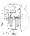
- FIG. 1 shows part of an exhaust pipe 1 carrying an exhaust support 2 fixed for example by welding to the pipe 1 on the side turned to the unrepresented body of the vehicle, under which the line exhaust must be mounted using a suspension and filtration pad 3 elastic.
- the support 2 comprises, perpendicular to the longitudinal axis A of the pipe 2, a plane fixing face 4 in which is made a through hole tapped 5.
- the suspension and filtration stud 3 comprises on the one hand an armature 6 metal for attachment to the vehicle body and on the other hand a frame 7 for fixing to the support 2, the armature 7 comprising for this purpose a part 8 forming a flange, pierced with a through hole 9.
- An inertial drummer 10, preferably in the form of a body of revolution, pierced with an axial passage hole 11 has at one end an interface 12 in washer shape.
- the through hole 11 is a stepped hole comprising on the side of the interface 12 a portion 11a of small diameter connected by a shoulder 11b to a portion 11c of large diameter (counterbore).
- the suspension stud 3 With its armatures 6 and 7 and the drummer 10, positions the three elements on a not shown assembly table, the flange 8 being interposed between the face 4 of the support 2 fixed to the pipe 1 and the interface 12 of the beater 10, the holes 5, 9 and 11 being aligned.
- the head 15a of a fixing screw 15 and the threaded rod 15b of the screw 15 is engaged with through the hole 11 of the beater 10 and the hole 9 of the flange 8 of the armature 7 of the pad 3 in the threaded hole 5 of the face 4 of the support 2, by pressing the sleeve 13 of the screwdriver 14, the mixer 10 and the flange 8 against the face 4 of the support 2, and the screwing is initiated in the tapped hole 5, this operation being facilitated by guiding the sleeve 13 of the screwdriver 14 in the counterbore 11c constituted by the large diameter portion of the hole 11.
- the through hole 9 in the flange 8 of the frame 7 of the 3 may advantageously be constituted by an elongated buttonhole in a direction perpendicular to the vehicle body, which allows a position isostatic of the exhaust line on the assembly table, the dispersions in this direction of the exhaust pipe and the exhaust support being absorbed by the buttonhole.
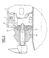
- FIG. 2 differs from that of FIG. 1 by the prediction, on the flange 8 of the armature 7 of the stud 3, the side of the drummer 10, projections 16 which, cooperating with female fingerprints 17 of shape corresponding drummer 10, act as anti-rotation means.
- inertial drummer could in principle present a form other than revolution but the form of revolution is preferable in so far as it exempts from any indexation provision and immobilization in rotation during assembly.
- the fixing screw 15 could also comprise a head other than the head 15a with external cavity, in which case the sleeve 13 of the screwdriver would replaced by another accessory or tip or a screwdriver accessory capable of being guided in the countersink 11c of the hole 11 of the beater 10.
Landscapes
- Engineering & Computer Science (AREA)
- Mechanical Engineering (AREA)
- General Engineering & Computer Science (AREA)
- Chemical & Material Sciences (AREA)
- Combustion & Propulsion (AREA)
- Transportation (AREA)
- Cooling, Air Intake And Gas Exhaust, And Fuel Tank Arrangements In Propulsion Units (AREA)
- Exhaust Silencers (AREA)
Claims (7)
- Kraftfahrzeugabgasanlage, umfassend ein Auspuffrohr (1), einen Auspuffträger (2), befestigt an das Auspuffrohr, Mittel zur Aufhängung und zur Filtrierung (3), befestigt zwischen dem Auspuffträger und dem Gehäuse des Fahrzeugs, und eine inerte Schwingungsdämpfungsmasse (10), wobei die Schwingungsdämpfungsmasse (10) an das Auspuffrohr (1) befestigt ist am Ort des Auspuffträgers (2),
dadurch gekennzeichnet, dass die Mittel (15) zur Befestigung der Schwingungsdämpfungsmasse (10) an das Auspuffrohr (1) am Ort des Auspuffträgers gleichfalls die Befestigung von Mitteln zur Aufhängung und zur Filtrierung (3) an den Auspuffträger (2) sicherstellen. - Abgasanlage gemäß Anspruch 1, dadurch gekennzeichnet, dass die Mittel zur Aufhängung und zur Filtrierung zwei Armaturen (6, 7) umfassen, die untereinander durch einen elastischen Block (3) verbunden sind, und die Armierung (7) an der Seite des Auspuffrohrs umfasst einen Abschnitt, welcher einen Flansch (8) bildet, der zwischen die Schwingungsdämpfungsmasse (10) und den Auspuffträger (2) eingeschoben ist, wobei die Schwingungsdämpfungsmasse, der Flansch und der Auspuffträger durch eine Befestigungsschraube (15) zusammengefügt sind.
- Abgasanlage gemäß Anspruch 2, dadurch gekennzeichnet, dass die Befestigungsschraube (15) von der Schwingungsdämpfungsmasse (10) durch ein Durchloch (9) des Flansches (8) mit einem mit einem Gewinde versehenen Loch (5) des Auspuffträgers (2) in Eingriff ist.
- Abgasanlage gemäß Anspruch 3, dadurch gekennzeichnet, dass das Durchloch (9) in dem Flansch (8) ein Knopfloch ist, das in einer zum Gehäuse des Fahrzeugs rechtwinkligen Richtung verlängert ist.
- Abgasanlage gemäß Anspruch 3, dadurch gekennzeichnet, dass die Schwingungsdämpfungsmasse (10) für die Befestigungsschraube (15) ein gestuftes Durchloch (11) umfasst, welches auf der verlängerten Seite des Auspuffträgers (2) eine Führung (11c) für den Kopf (15a) der Schraube aufweist.
- Abgasanlage gemäß Anspruch 5, dadurch gekennzeichnet, dass der Durchmesser der Führung (11c) gewählt ist in Abhängigkeit von dem Kopf (15a) der Befestigungsschraube (15) und dem Verschraubungszubehör (13) eines Schraubers, derart, dass die Führung als Führung für den Schrauber dient.
- Abgasanlage gemäß einem der Ansprüche 2 bis 6, dadurch gekennzeichnet, dass der Flansch (8) der Armierung (7) des Blocks der Aufhängung und der Filtrierung (3) auf der Seite der Schwingungsdämpfungsmasse (10) wenigstens einen Vorsprung (16) aufweist, der, indem er mit wenigstens einer weiblichen Vertiefung (17) von entsprechender Form der Schwingungsdämpfungsmasse (10) zusammenwirkt, das Amt der Anti-Rotationsmittel ausübt.
Applications Claiming Priority (2)
| Application Number | Priority Date | Filing Date | Title |
|---|---|---|---|
| FR0112300 | 2001-09-25 | ||
| FR0112300A FR2829972B1 (fr) | 2001-09-25 | 2001-09-25 | Ligne d'echappement de vehicule automobile, comportant un batteur inertiel |
Publications (2)
| Publication Number | Publication Date |
|---|---|
| EP1297983A1 EP1297983A1 (de) | 2003-04-02 |
| EP1297983B1 true EP1297983B1 (de) | 2005-01-26 |
Family
ID=8867569
Family Applications (1)
| Application Number | Title | Priority Date | Filing Date |
|---|---|---|---|
| EP20020292251 Expired - Lifetime EP1297983B1 (de) | 2001-09-25 | 2002-09-13 | Kraftfahrzeugabgasanlage mit inertialer Schwingungsdämpfungsmasse |
Country Status (4)
| Country | Link |
|---|---|
| EP (1) | EP1297983B1 (de) |
| DE (1) | DE60202728T2 (de) |
| ES (1) | ES2232721T3 (de) |
| FR (1) | FR2829972B1 (de) |
Families Citing this family (1)
| Publication number | Priority date | Publication date | Assignee | Title |
|---|---|---|---|---|
| FR3083580B1 (fr) | 2018-07-05 | 2021-03-19 | Renault Sas | Dispositif d'amortissement de vibrations d'un composant mecanique |
Family Cites Families (5)
| Publication number | Priority date | Publication date | Assignee | Title |
|---|---|---|---|---|
| FR2570785B1 (fr) * | 1984-09-25 | 1989-02-24 | Renault | Amortisseur de vibrations de torsion |
| FR2710381B1 (fr) * | 1993-09-23 | 1995-11-24 | Hutchinson | Batteur pour barre vibrante. |
| FR2758602B1 (fr) * | 1997-01-17 | 1999-04-02 | Hutchinson | Dispositif de suspension elastique pour tubulure d'echappement |
| FR2761730B1 (fr) * | 1997-04-04 | 1999-06-25 | Hutchinson | Suspente pour tubulure d'echappement de vehicule automobile |
| FR2805870B1 (fr) * | 2000-03-06 | 2002-06-14 | Hutchinson | Dispositif elastique de suspension d'une structure vibrante a une structure rigide |
-
2001
- 2001-09-25 FR FR0112300A patent/FR2829972B1/fr not_active Expired - Fee Related
-
2002
- 2002-09-13 EP EP20020292251 patent/EP1297983B1/de not_active Expired - Lifetime
- 2002-09-13 DE DE2002602728 patent/DE60202728T2/de not_active Expired - Fee Related
- 2002-09-13 ES ES02292251T patent/ES2232721T3/es not_active Expired - Lifetime
Also Published As
| Publication number | Publication date |
|---|---|
| ES2232721T3 (es) | 2005-06-01 |
| FR2829972A1 (fr) | 2003-03-28 |
| EP1297983A1 (de) | 2003-04-02 |
| FR2829972B1 (fr) | 2003-12-12 |
| DE60202728T2 (de) | 2005-12-29 |
| DE60202728D1 (de) | 2005-03-03 |
Similar Documents
| Publication | Publication Date | Title |
|---|---|---|
| EP2430321B1 (de) | Vorrichtung zur befestigung eines ersten teils an einem zweiten teil, das an einem dritten teil befestigt ist und montage von drei teilen, insbesondere eines kraftfahrzeugs | |
| FR2720450A1 (fr) | Dispositif de fixation d'un ensemble sur la caisse d'un véhicule automobile et module d'essuyage comportant un tel dispositif. | |
| EP1297983B1 (de) | Kraftfahrzeugabgasanlage mit inertialer Schwingungsdämpfungsmasse | |
| FR2971980A1 (fr) | Vehicule comportant un absorbeur de choc et absorbeur de choc correspondant | |
| FR2776606A1 (fr) | Unite d'essuie-glace | |
| EP0491603B1 (de) | Verbindungsglied zwischen einem Scheibenwischerarm, insbesondere für Kraftfahrzeug | |
| JP3542949B2 (ja) | ハンドレール装置 | |
| FR2796427A1 (fr) | Dispositif de premontage d'un ecrou pour ensemble de fixation du type vis-ecrou | |
| FR2722549A1 (fr) | Embrayage a friction | |
| EP1640620B1 (de) | Vorrichtung zum Befestigen und zum Filtern von Schwingungen und Montageverfahren mit derselben in der Kraftfahrzeugindustrie | |
| FR2795783A1 (fr) | Dispositif de liaison mecanique a amortissement | |
| EP0867316A1 (de) | Vorrichtung zur Befestigung des oberen Endteils eines Federbeins an der Fahrzeugkarosserie | |
| FR2817601A1 (fr) | Double volant amortisseur pour mecanisme d'embrayage de vehicule automobile | |
| FR2847959A1 (fr) | Dispositif antivibratoire | |
| FR2630507A1 (fr) | Dispositif de fixation, notamment d'un amortisseur sur un vehicule automobile | |
| JPH09310735A (ja) | 自動車部材の揺動支持装置 | |
| EP1692385A1 (de) | Motorlagervorrichtung | |
| JPS6236712Y2 (de) | ||
| FR3058192B1 (fr) | Ensemble de collier de serrage et de fixation | |
| EP1104736A1 (de) | Vorrichtung zum Verbinden eines Lenkungsritzels mit einem Bügel | |
| FR2826411A1 (fr) | Dispositif de liaison mecanique securise | |
| FR2719639A1 (fr) | Dispositif antivibratoire pour câble de commande travaillant en traction. | |
| FR2762885A1 (fr) | Dispositif amortisseur entre deux pieces mecaniques, notamment pour un equipement de vehicule automobile | |
| EP2851917B1 (de) | Positionsschalter | |
| EP1457691A2 (de) | Verfahren zum Montieren einer Pleuelstange auf einer Stützfläche sowie nach diesem Verfahren hergestellter Schwingungsdämpfer |
Legal Events
| Date | Code | Title | Description |
|---|---|---|---|
| PUAI | Public reference made under article 153(3) epc to a published international application that has entered the european phase |
Free format text: ORIGINAL CODE: 0009012 |
|
| AK | Designated contracting states |
Kind code of ref document: A1 Designated state(s): AT BE BG CH CY CZ DE DK EE ES FI FR GB GR IE IT LI LU MC NL PT SE SK TR Designated state(s): AT BE BG CH CY CZ DE DK EE ES FI FR GB GR IE IT LI LU MC NL PT SE SK TR |
|
| AX | Request for extension of the european patent |
Extension state: AL LT LV MK RO SI |
|
| 17P | Request for examination filed |
Effective date: 20030918 |
|
| AKX | Designation fees paid |
Designated state(s): BE DE ES IT |
|
| GRAP | Despatch of communication of intention to grant a patent |
Free format text: ORIGINAL CODE: EPIDOSNIGR1 |
|
| RTI1 | Title (correction) |
Free format text: AUTOMOTIVE VEHICLE EXHAUST LINE WITH INERTIAL VIBRATION DAMPENING MASS |
|
| GRAS | Grant fee paid |
Free format text: ORIGINAL CODE: EPIDOSNIGR3 |
|
| GRAA | (expected) grant |
Free format text: ORIGINAL CODE: 0009210 |
|
| AK | Designated contracting states |
Kind code of ref document: B1 Designated state(s): BE DE ES IT |
|
| REF | Corresponds to: |
Ref document number: 60202728 Country of ref document: DE Date of ref document: 20050303 Kind code of ref document: P |
|
| REG | Reference to a national code |
Ref country code: ES Ref legal event code: FG2A Ref document number: 2232721 Country of ref document: ES Kind code of ref document: T3 |
|
| PLBE | No opposition filed within time limit |
Free format text: ORIGINAL CODE: 0009261 |
|
| STAA | Information on the status of an ep patent application or granted ep patent |
Free format text: STATUS: NO OPPOSITION FILED WITHIN TIME LIMIT |
|
| 26N | No opposition filed |
Effective date: 20051027 |
|
| PGFP | Annual fee paid to national office [announced via postgrant information from national office to epo] |
Ref country code: DE Payment date: 20060926 Year of fee payment: 5 |
|
| PGFP | Annual fee paid to national office [announced via postgrant information from national office to epo] |
Ref country code: ES Payment date: 20060928 Year of fee payment: 5 |
|
| PGFP | Annual fee paid to national office [announced via postgrant information from national office to epo] |
Ref country code: IT Payment date: 20060930 Year of fee payment: 5 |
|
| PGFP | Annual fee paid to national office [announced via postgrant information from national office to epo] |
Ref country code: BE Payment date: 20061012 Year of fee payment: 5 |
|
| BERE | Be: lapsed |
Owner name: *RENAULT S.A.S. Effective date: 20070930 |
|
| PG25 | Lapsed in a contracting state [announced via postgrant information from national office to epo] |
Ref country code: DE Free format text: LAPSE BECAUSE OF NON-PAYMENT OF DUE FEES Effective date: 20080401 |
|
| PG25 | Lapsed in a contracting state [announced via postgrant information from national office to epo] |
Ref country code: BE Free format text: LAPSE BECAUSE OF NON-PAYMENT OF DUE FEES Effective date: 20070930 |
|
| REG | Reference to a national code |
Ref country code: ES Ref legal event code: FD2A Effective date: 20070914 |
|
| PG25 | Lapsed in a contracting state [announced via postgrant information from national office to epo] |
Ref country code: ES Free format text: LAPSE BECAUSE OF NON-PAYMENT OF DUE FEES Effective date: 20070914 |
|
| PG25 | Lapsed in a contracting state [announced via postgrant information from national office to epo] |
Ref country code: IT Free format text: LAPSE BECAUSE OF NON-PAYMENT OF DUE FEES Effective date: 20070913 |