EP1297317B1 - Viscosimetre quasi-statique - Google Patents
Viscosimetre quasi-statique Download PDFInfo
- Publication number
- EP1297317B1 EP1297317B1 EP00941320A EP00941320A EP1297317B1 EP 1297317 B1 EP1297317 B1 EP 1297317B1 EP 00941320 A EP00941320 A EP 00941320A EP 00941320 A EP00941320 A EP 00941320A EP 1297317 B1 EP1297317 B1 EP 1297317B1
- Authority
- EP
- European Patent Office
- Prior art keywords
- cavity
- viscosity
- sensor
- driver
- pressure
- Prior art date
- Legal status (The legal status is an assumption and is not a legal conclusion. Google has not performed a legal analysis and makes no representation as to the accuracy of the status listed.)
- Expired - Lifetime
Links
- 239000012530 fluid Substances 0.000 claims abstract description 22
- 238000010438 heat treatment Methods 0.000 claims abstract description 7
- 238000000034 method Methods 0.000 claims 2
- QVGXLLKOCUKJST-UHFFFAOYSA-N atomic oxygen Chemical compound [O] QVGXLLKOCUKJST-UHFFFAOYSA-N 0.000 abstract description 9
- 239000001301 oxygen Substances 0.000 abstract description 9
- 229910052760 oxygen Inorganic materials 0.000 abstract description 9
- 239000012528 membrane Substances 0.000 abstract description 8
- 239000007789 gas Substances 0.000 description 27
- 239000000446 fuel Substances 0.000 description 22
- 238000002485 combustion reaction Methods 0.000 description 12
- 238000005259 measurement Methods 0.000 description 11
- 230000008859 change Effects 0.000 description 9
- ATUOYWHBWRKTHZ-UHFFFAOYSA-N Propane Chemical compound CCC ATUOYWHBWRKTHZ-UHFFFAOYSA-N 0.000 description 8
- VNWKTOKETHGBQD-UHFFFAOYSA-N methane Chemical compound C VNWKTOKETHGBQD-UHFFFAOYSA-N 0.000 description 8
- 238000006073 displacement reaction Methods 0.000 description 7
- 239000007788 liquid Substances 0.000 description 7
- 239000000203 mixture Substances 0.000 description 7
- IJGRMHOSHXDMSA-UHFFFAOYSA-N Atomic nitrogen Chemical compound N#N IJGRMHOSHXDMSA-UHFFFAOYSA-N 0.000 description 6
- 230000000694 effects Effects 0.000 description 6
- 230000003534 oscillatory effect Effects 0.000 description 5
- 230000001419 dependent effect Effects 0.000 description 4
- 230000000875 corresponding effect Effects 0.000 description 3
- 230000005284 excitation Effects 0.000 description 3
- 239000002737 fuel gas Substances 0.000 description 3
- 229910052757 nitrogen Inorganic materials 0.000 description 3
- 238000012545 processing Methods 0.000 description 3
- 229910001369 Brass Inorganic materials 0.000 description 2
- 238000013459 approach Methods 0.000 description 2
- 230000004888 barrier function Effects 0.000 description 2
- 239000010951 brass Substances 0.000 description 2
- 239000013078 crystal Substances 0.000 description 2
- 238000004519 manufacturing process Methods 0.000 description 2
- 230000000737 periodic effect Effects 0.000 description 2
- 239000001294 propane Substances 0.000 description 2
- 239000010453 quartz Substances 0.000 description 2
- VYPSYNLAJGMNEJ-UHFFFAOYSA-N silicon dioxide Inorganic materials O=[Si]=O VYPSYNLAJGMNEJ-UHFFFAOYSA-N 0.000 description 2
- 239000004215 Carbon black (E152) Substances 0.000 description 1
- WDVSHHCDHLJJJR-UHFFFAOYSA-N Proflavine Chemical compound C1=CC(N)=CC2=NC3=CC(N)=CC=C3C=C21 WDVSHHCDHLJJJR-UHFFFAOYSA-N 0.000 description 1
- 239000006096 absorbing agent Substances 0.000 description 1
- 230000002547 anomalous effect Effects 0.000 description 1
- 239000000470 constituent Substances 0.000 description 1
- 230000008602 contraction Effects 0.000 description 1
- 238000012937 correction Methods 0.000 description 1
- 230000002596 correlated effect Effects 0.000 description 1
- 230000008878 coupling Effects 0.000 description 1
- 238000010168 coupling process Methods 0.000 description 1
- 238000005859 coupling reaction Methods 0.000 description 1
- 238000013016 damping Methods 0.000 description 1
- 238000001514 detection method Methods 0.000 description 1
- 230000002542 deteriorative effect Effects 0.000 description 1
- 238000009792 diffusion process Methods 0.000 description 1
- 238000011067 equilibration Methods 0.000 description 1
- 238000002474 experimental method Methods 0.000 description 1
- 239000008246 gaseous mixture Substances 0.000 description 1
- 230000005484 gravity Effects 0.000 description 1
- 229930195733 hydrocarbon Natural products 0.000 description 1
- 150000002430 hydrocarbons Chemical class 0.000 description 1
- 238000007654 immersion Methods 0.000 description 1
- 238000003475 lamination Methods 0.000 description 1
- 230000007774 longterm Effects 0.000 description 1
- 239000000463 material Substances 0.000 description 1
- 239000003345 natural gas Substances 0.000 description 1
- 239000011148 porous material Substances 0.000 description 1
- 230000004044 response Effects 0.000 description 1
- 230000035945 sensitivity Effects 0.000 description 1
- 230000036962 time dependent Effects 0.000 description 1
- 238000012546 transfer Methods 0.000 description 1
- XLYOFNOQVPJJNP-UHFFFAOYSA-N water Substances O XLYOFNOQVPJJNP-UHFFFAOYSA-N 0.000 description 1
Images


Classifications
-
- G—PHYSICS
- G01—MEASURING; TESTING
- G01N—INVESTIGATING OR ANALYSING MATERIALS BY DETERMINING THEIR CHEMICAL OR PHYSICAL PROPERTIES
- G01N11/00—Investigating flow properties of materials, e.g. viscosity, plasticity; Analysing materials by determining flow properties
- G01N11/02—Investigating flow properties of materials, e.g. viscosity, plasticity; Analysing materials by determining flow properties by measuring flow of the material
- G01N11/04—Investigating flow properties of materials, e.g. viscosity, plasticity; Analysing materials by determining flow properties by measuring flow of the material through a restricted passage, e.g. tube, aperture
- G01N11/08—Investigating flow properties of materials, e.g. viscosity, plasticity; Analysing materials by determining flow properties by measuring flow of the material through a restricted passage, e.g. tube, aperture by measuring pressure required to produce a known flow
-
- G—PHYSICS
- G01—MEASURING; TESTING
- G01N—INVESTIGATING OR ANALYSING MATERIALS BY DETERMINING THEIR CHEMICAL OR PHYSICAL PROPERTIES
- G01N33/00—Investigating or analysing materials by specific methods not covered by groups G01N1/00 - G01N31/00
- G01N33/22—Fuels; Explosives
- G01N33/225—Gaseous fuels, e.g. natural gas
Definitions
- the present invention pertains to viscosity detectors and particularly to delta-pressure-based sensors. More particularly, the invention pertains to viscosity sensors for determining the oxygen demand (for complete combustion) of a gaseous or liquid fuel for combustion purposes.
- the proposed sensor measures a known property of fluids, viscosity. When applied to a combustion control system, it enables feed-forward operation and sensing in the mild pre-combustion environment; it is low-cost because the property can be simply proportional to the measured signal (in one preferred measurement approach) and it relates also simply to Wobbe number, oxygen demand or heating value of the fuel, so that the sensing error makes a relatively small contribution to the total combustion control error.
- This invention involves the use or application of a known property, viscosity, to combustion control. It is also about using a preferred approach to viscosity measurement to that application.
- Viscosity, ⁇ may be known best for its linear relation to laminar volumetric flow (dV/dt) and pressure drop, ⁇ p, in a capillary (of radius, r c , and length, L c ), as shown in equation (1).
- dV / dt ⁇ pr c 4 / 8 ⁇ L c ⁇ ⁇
- Figure 1 shows graphically a comparison between ⁇ , curve 23, and other fuel gas thermophysical (Q i ) properties, i.e., ⁇ ,density, curve 26; k, thermal conductivity, curve 24; c p , specific heat, curve 25; and C v , thermal anemometer correction factor, curve 27; and how well they correlate individually with oxygen demand of fuel, D 02 .
- Q i fuel gas thermophysical
- the c p value of noncombustible CO 2 (8.83 cal/(mol ⁇ K); 8.60 for H 2 O) lies between that of CH 4 and C 2 H 6 (8.50 and 12.42), but all ⁇ -values of noncombustible gases O 2 , N 2 , CO 2 (except H 2 O) lie above that of CH 4 .
- Wb ⁇ H/m*
- ⁇ h heating value rather than O 2 demand
- m* (M gas /M air ) 0.5 .
- M moles
- a and B are correlation coefficients and C is a correlation exponent.
- A' and B' are similarly correlation coefficients.
- the correlation is like that of natural law.
- Related information is in figure 6 , page 21, of "Microsensors for Fluid Properties", by U. Bonne and D. Kubisiak, Scientific Honeyweller, Sensors Issue (1996). Additional information is in U.S. Patent 5,486,107 by U. Bonne, issued January 23, 1996 and entitled “Determination of Fuel Characteristics”.
- Table 1 compares some parameters relevant to the quality of a combustion control system based on thermal conductivity versus viscosity sensors. As shown, on all counts, the viscosity-based system lists more advantageous values such as smaller sensor output dependence on pressure and temperature but larger dependence fuel-gas composition or fuel concentration in a fuel + air mixture. The latter parameter was included to quantify the merits of direct measurement of thermo-physical properties of the fuel + air mixtures; as shown, measurement of viscosity or thermal conductivity in a premixed fuel + air mixture makes the pressure, temperature and humidity effects much larger than the sought fuel property effects. A similar case can be made for the measurement of ⁇ or k in the stack gases.
- Table 1 indicates advantages of viscosity versus thermal conductivity as D O2 or ⁇ , wavelength, sensors.
- ⁇ (actual fuel/air ratio) ⁇ (stoichiometric air/fuel ratio).
- This table indicates that viscosity is approximately two times more sensitive to changes in ⁇ and D O2 than thermal conductivity, but thirty percent less sensitive to variations in pressure and temperature. That means viscosity detection results in a several times more accurate sensor than thermal conductivity, for D O2 or ⁇ measurement.
- the gas G20 is methane and G271 is a gas mixture of 74 percent methane and 26 percent nitrogen.
- p is pressure in bars, and T, temperature, is in degrees Celsius.
- W is the dependent variable, measuring the desired property ( ⁇ or D O2 ).
- Sensitivities of k and ⁇ are relative to variability in nitrogen content of fuel mixed with air, ⁇ , T, p and nitrogen content of pure fuel gas.
- SU-A-1746256 relates to a turbulent sound-generator which is immersed in a liquid to be tested using a gas-transmitting tube and a turbulent flow of gas from the sound-sources formed through a layer of the liquid, forming a channel with fluid walls.
- vibrations are formed, accompanied by a change of the form of the channel and the frequency of periodic change is determined by this feed of movement of the liquid wave along the channel.
- the amplitude of the sub-sonic vibrations determined by the amplitude of the liquid wave and acoustic amplitude-modulated vibrations pass through a microphone carrying information on the viscosity of the tested liquid.
- the amplitude and frequency of these vibrations are fixed by meters respectively and are used to assess the viscosity.
- the viscometer disclosed here does not rely on the availability of pressurized gas, a microsensor or on thermal drivers, and its output is independent of absolute pressure (to the extent that viscosity is). It is not sensitive to orientation and can be fabricated at low cost.
- the present viscosity sensor is used for determining the oxygen demand of various gaseous mixtures. It has a fluid volume-displacer, actuator or driver, such as a speaker membrane, and a pressure sensor or detector, such as a microphone, with a chamber or cavity and a controlled leak between the cavity and the ambient environment of the viscosity sensor.
- the driver, the leak and sensor electronics can be assembled from commercially available and inexpensive components. In sum, the sensor has low manufacturing costs, and good accuracy, reliability, intrinsic safety and long service life.
- a device for use in a quasi-static viscometer as defined in claim 1.
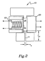
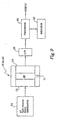
- a viscometer 10 of figure 2 makes use of a linear relationship between laminar volumetric flow (dV/dt) through a controlled leak, for which we shall choose at first a capillary (C) 11, (of radius, r c , and length, L c , of capillary tube 11) and viscosity, ⁇ , for a pressure difference, ⁇ p.
- C capillary
- ⁇ viscosity
- a valve or a mechanical flow is used to induce a repeatable but time-dependent flow and enable the observation of a pressure drop (or rise), ⁇ p, time constant, ⁇ , or phase lag, ⁇ .
- Viscometer 10 disclosed here is designed to induce a repeatable but time-independent flow to enable the observation of a steady ⁇ p when the rate of volumetric displacement by an actuator 12 and the actual leakage flow become equal for a few milliseconds (ms). This is sketched out and represented in Figures 2 and 3 .
- the ⁇ p signals for three gases, Ar, N2 and C 3 H 8 are marked as curves 13, 14 and 15, respectively, and the volume change ⁇ V c , in percent, of cavity 16, shown by saw-tooth curve 17, represents the volumetric change induced by actuator or driver 12.
- actuator 12 can be driven in a "saw tooth" mode and at constant frequency, f, and the above equation (1) indeed establishes itself; then all types of gases will eventually reach their own ⁇ p in the chamber, but at the same capillary 11 flow rate, thus enabling the determination of each fluid's viscosity via measurement of ⁇ p and use of equation (2). If one designs viscometer 10 to meet the first two above-noted assumptions, the remaining question is whether there will be enough time in one half-cycle to establish the above quality.
- the viscosity then results from equation (3).
- ⁇ ⁇ pr c 4 / 8 ⁇ ⁇ V c ⁇ f ⁇ L c
- Viscosity, ⁇ is an indication of oxygen demand, D O2 , of the fluid.
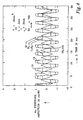
- Figure 3 is a graph of ⁇ p, pressure amplitude in cm water column (WC) versus z or time in ms.
- This graph shows an oscillatory volume 17 and ⁇ p of a leaky cavity 16 for three gases Ar, N 2 and C 3 H 8 , as represented by curves 13, 14 and 15, respectively.
- the oscillatory volume 17 of cavity 16 is the result of electrical input to actuator 12.
- the pressure sensor changes, as indicated by curves 13, 14 and 15, are detected by sensor 20. These plots were taken at 22°C and a pressure of 0.7 bar.
- the frequency, f, is 132 Hz.
- R v is one percent.
- the pressure equilibration times to 63% of the final ⁇ p, ⁇ , are 0.40, 0.23 and 0.153 ms for the three gases, respectively.
- the cavity volume at rest, V co is 0.15 cm 3
- capillary length L c and radius r c are at 0.3 cm and 0.17 cm, respectively.
- the maximum Reynolds number, Re max is 752.
- Figure 4 is a graph of ⁇ p, pressure amplitude in cm WC versus time in ms, z.
- This graph shows an oscillatory volume 17 and ⁇ p of leaky cavity 16 for three gases Ar, N 2 and C 3 H 8 , as represented by curves 13, 14 and 15.
- These plots were taken at 22° C and a pressure of 0.7 bar.
- Frequency f is 323 Hz, which is about 2.447 times faster than f for figure 2 .
- R v is 0.5%
- ⁇ z is 0.05 ms and the linear excitation, ⁇ , is 0.18 ms.
- V co and L c are the same as for figure 3 .
- the capillary radius, r c is larger at 0.2 mm.
- the maximum Reynolds number is 785. Note that the amplitudes of corresponding curves 13, 14 and 15 are about half of those for the curves in figure 3 . However, the amplitude differences between curves 13, 14 and 15 appear to be more distinguishable
- Figure 5 is a graph of ⁇ p, pressure amplitude in cm WC versus Z, time in ms. This graph shows an oscillatory volume 17 and ⁇ p of leaky cavity 16 for N 2 at three different absolute pressures, p a .
- Curve 14 is for N 2 at 0.7 bar
- curve 18 is for N 2 at 1.0 bar
- curve 19 is for N 2 at 1.5 bar.
- This data was taken from device 10 at 22° C and a frequency of 122 Hz, and R v is equal to 1%.
- V co 0.15 cm 3
- L c is 0.3 cm
- r c 0.14 mm
- Re max is at 846.
- time constants to reach equilibrium, ⁇ are pressure dependent: time constants of about 0.29, 0.23 and 0.194 ms were derived for the pressures of 0.7, 1.0 and 1.5 bar, respectively, which may also serve to determine absolute pressure after viscosity has been determined: p a ⁇ 2 ⁇ constant.
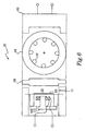
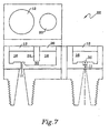
- Figures 6 and 7 show additional embodiments 21 and 22, respectively, featuring interfaces or coupling devices 28 and 29 that may be baffles or at least partial barriers between drivers 12 and sensors 20.
- Barrier 28 or 29 is for preventing transport from driver 12 to sensor or detector 20 any physical energy (i.e., mechanical, electrical, and/or thermal) which may hinder, delay or inhibit the transfer of ⁇ p information from driver 12 to detector 20.
- Baffle 28 or 29 may prevent such possible distortion or dilapidation by effecting diffusion, attenuation or other appropriately affecting function.
- Viscometer 21 has a baffle 28 situated in cavity 16 between actuator 12 and sensor 20.
- Baffle or diffuser plate 28 has apertures or holes 32 so that driver 12 can affect sensor 20 via the tested gas and apertures 32.
- the gas enters cavity 16 via capillary 11.
- A.front view of diffuser plate 28 is shown to illustrate apertures 32.
- Viscometer 22 has a baffle, bar or damping channel 29 situated in cavity 16 between actuator 12 and sensor 20.
- a passage or hole 30 provides for passage of the tested gas so that driver 12 can affect sensor 20, for viscosity determination of the gas.
- the controlled cavity leak is though capillary opening 11.
- Actuators may be of several kinds. To generate constant rate of volumetric expansion or contraction, one can consider a bulk (piezoelectric) PZT expansion, PZT bimorph actuators as used in tweeters and electromagnetic speakers as drivers 12. Volumetric expansion of piezoelectric transducers is attractive because of the large forces involved, which would not be affected by changes in gas density, although the displacements would be very small. Both PZT expansion and PZT bimorph actuators would need to be temperature-compensated, which would not be required in the instance of electromagnetic speakers.
- Measured center deflections were made of a bimorph actuator (PZT/brass lamination by Mallory Sonalert of Indianapolis, IN, at $0.55/each at a 25-99 quantity) consisting of a 15 mm OD/0.11 mm-thick brass support + a 10 mm OD/0.11 mm-thick PZT + 9 mm OD/0.02 mm-thick Ag electrode film. Under the rated voltage of ⁇ 25 V, the center deflection was about 0.8 ⁇ m/VRMS. Center deflection measurements were also made of an electromagnetic speaker (BRT1209P-01, from Int'1. Components Co.
- BRT1209P-01 an electromagnetic speaker
- chamber or cavity 16 is sealed to eliminate leaks across speaker membrane 33, then the side opposite to its V c side needs to be opened to an ambient/external fluid to avoid anomalous effects when the ambient pressure or temperature changes. If the volume on the membrane 33 side opposite of the cavity 16 side is not sealed leaktight from cavity 16 (as in BRT1206P-01), then it competes with capillary 11 and/or the leak functions as an orifice.
- Sensors may be of several kinds. Another function needed for viscometer 10 is the ⁇ p sensor 20 between ambient and V c . Microphones may be the lowest-cost choice to meet that need.
- the ideal sensor 20 would be a rigid microphone, i.e., lack of influence on V c via deformation, with a frequency-independent output.
- a MICRO SWITCH 24PC pressure sensor chip from Honeywell Inc. of Freeport, IL, mounted and sealed on a TO5 header (over a center hole to avoid any back-pressure build-up) served well as a sensor 20, in operation with one of the BRT1206P-01 speakers serving as an actuator 12. It was verified that the sensor 20 output followed the shape of the driver 12 excitation (sine, square or saw-tooth shape) with capillary 11 plugged. After unplugging the capillary, a balance between rate of cavity 16 volume change and capillary 11 flow was achieved, demonstrating the invention. During this dynamic balance, the established ⁇ p was representative of the fluid viscosity.
- the L/D ratio of the capillary 11 tube should be greater than four.
- the capillary 11 inlet should be smooth internally and at the edges to minimize turbulence.
- Viscometer 10 may have several limitations.
- head pressure due to flow reversal As the frequency of a flow driver increases, the inertial pressure generated at each reciprocating flow reversal increases. In order to stay away from such effects, one may calculate the frequency at which the capillary 11 pressure drop, ⁇ p c , would equal the inertial pressure drop, ⁇ p i , as shown by equation (4).
- v ⁇ V c f/(2 ⁇ r 2 )
- f 16 ⁇ ⁇ ⁇ L c / ⁇ ⁇ V c .
- the components of the quasi-static viscometer 10 and their costs include a saw-tooth generator at $0.4, a speaker (10-15 mm diameter) at $0.22-0.25 (from DAI Ltd.), a microphone (6-10 mm diameter) at $0.22-0.25, a microphone amplifier and an analog-to-digital converter (A/D) for a digital output, at about $2.00, one or more 0.2-0.4 mm holes/capillaries of 3-6 mm in length, or equivalent controlled leaks made of porous materials, at $0.10, plus assembly, calibration and miscellaneous materials at about $3.00.
- the total cost of the sensor may be less than $6.00, so that its use and business potential is great.
- capillary 11 flow (known to be proportional to viscosity) to or from a cavity 16, an electro-mechanical fluid displacer/actuator 12 and a saw-tooth electronic drive 34 to enable the ⁇ p in cavity 16 to stabilize during at least one of the two periods of each AC actuation cycle.
- the measurement of the established ⁇ p at the end of (at least one or) each saw-tooth period is an indication of the desired viscosity. It is the ⁇ p (but not ⁇ p/p a ) which is largely independent of absolute pressure, p a .
- ⁇ p is sensed by sensor 20, which provides an output to an analog-to-digital converter 35, as shown in figure 9 . The digital output goes to processor 36 for processing.
- Processor 36 has a digital or analog output that may be provided to some apparatus such as a combustion control or regulator. Also, an output is provided to indicator 37 that may provide readable information about the directly measured viscosity, as well as correlated properties such as oxygen demand or other parameters of the tested gas. The output of sensor 20, instead, may go directly to an analog indicator, processor or interface.
- An embodiment may have an actuator 12 that is a low-voltage, electro-magnetic earphone speaker, rather than a piezo-electric tweeter or electro-static speaker, and in which the ⁇ p sensor 20 is a microphone based on either piezo-electric (preferred), piezo-resistive, electro-magnetic, electret, carbon-contact or capacitance effects.
- the present invention may sense not only viscosity but also absolute pressure by further processing the determined viscosity and the initial time constant or phase lag between actuator 12 input and sensor 20 output, as shown in figures 3-5 .
- Viscometers 10, 21 and 22 have advantages over related art viscometers based on vibrating wires and quartz crystal oscillators, having pressure decays or phase lags, because they have no dependence on absolute pressure. Viscometers 10, 21 or 22 also has advantages over viscometers based on thermal excitation, because it has no dependence on thermal conductivity or specific heat of the fluid being measured. It also has advantages over traditional viscometers based on capillary flow driven by a constant source of pressurized fluid, or based on timing of the fall of an object, in that there is no need for a costly source of constant pressure fluid, constant gravity magnitude and direction, or equipment for providing and measuring the falling object.
- the present viscometer is not sensitive to its mounting orientation. As noted above, besides viscosity, the present device can also be used to sense absolute pressure by using the initial time constant or phase lag between actuator input and sensor output, which is a feature not available from related art viscometers.
Landscapes
- Chemical & Material Sciences (AREA)
- Health & Medical Sciences (AREA)
- Life Sciences & Earth Sciences (AREA)
- Analytical Chemistry (AREA)
- Biochemistry (AREA)
- Pathology (AREA)
- Immunology (AREA)
- General Physics & Mathematics (AREA)
- General Health & Medical Sciences (AREA)
- Physics & Mathematics (AREA)
- Engineering & Computer Science (AREA)
- Medicinal Chemistry (AREA)
- Oil, Petroleum & Natural Gas (AREA)
- Food Science & Technology (AREA)
- Chemical Kinetics & Catalysis (AREA)
- General Chemical & Material Sciences (AREA)
- Measuring Fluid Pressure (AREA)
- Agricultural Chemicals And Associated Chemicals (AREA)
- Fats And Perfumes (AREA)
- Examining Or Testing Airtightness (AREA)
- Investigating Or Analyzing Materials Using Thermal Means (AREA)
Claims (8)
- Dispositif destiné à être utilisé dans un viscosimètre (10) quasi statique comprenant :un amplificateur (12) ayant un diaphragme (33),un capteur (20) ayant un diaphragme situé à une première distance du diaphragme (33) dudit amplificateur (12),caractérisé en ce qu'un ajustage est formé entre les périphéries du diaphragme dudit amplificateur (12) et dudit capteur (20) et autour de celles-ci de façon à former une cavité (16) entre les diaphragmes, etune ouverture (11) est formée sur ledit ajustage pour fournir une fuite pour la cavité (12).
- Dispositif (10) selon la revendication 1, comprenant en outre une interface située dans la cavité (16) entre le diaphragme (33) dudit amplificateur (12) et le diaphragme dudit capteur (20), dans lequel la cavité (16) est divisée en deux cavités secondaires.
- Dispositif (10) selon la revendication 2, dans lequel ladite interface a une pluralité de trous.
- Dispositif (10) selon la revendication 3, dans lequel :ledit amplificateur (12) est un haut-parleur, etledit capteur (20) est un microphone.
- Dispositif (10) selon la revendication 4, comprenant en outre :un générateur de signaux connecté audit amplificateur (12), etun processeur (36) connecté audit capteur (20).
- Dispositif (10) selon la revendication 5, dans lequel ledit processeur (36) traite les signaux provenant dudit capteur (20) en des indications de viscosité d'un fluide à l'intérieur de la cavité (16).
- Dispositif (10) selon la revendication 6, dans lequel ledit processeur (36) traite les indications de viscosité en des indications d'une valeur de chauffage D02 du fluide à l'intérieur de la cavité (16).
- Dispositif (10) selon la revendication 7, dans lequel :ladite ouverture est un tube capillaire (11) ayant une longueur Lc et un rayon rc,ledit générateur de signaux fournit un signal ayant une fréquence f audit amplificateur,ledit amplificateur (12) fait qu'un volume Δvc d'un fluide entre dans la cavité (16) et la quitte à une variation de pression Δp, etla viscosité η du fluide à l'intérieur de la cavité (16) est égale à (πΔprc 4) / (4ΔVcfLc).
Applications Claiming Priority (1)
| Application Number | Priority Date | Filing Date | Title |
|---|---|---|---|
| PCT/US2000/015967 WO2001096832A1 (fr) | 2000-06-09 | 2000-06-09 | Viscosimetre quasi-statique |
Publications (2)
| Publication Number | Publication Date |
|---|---|
| EP1297317A1 EP1297317A1 (fr) | 2003-04-02 |
| EP1297317B1 true EP1297317B1 (fr) | 2009-03-18 |
Family
ID=21741474
Family Applications (1)
| Application Number | Title | Priority Date | Filing Date |
|---|---|---|---|
| EP00941320A Expired - Lifetime EP1297317B1 (fr) | 2000-06-09 | 2000-06-09 | Viscosimetre quasi-statique |
Country Status (7)
| Country | Link |
|---|---|
| EP (1) | EP1297317B1 (fr) |
| JP (1) | JP2004503767A (fr) |
| AT (1) | ATE426153T1 (fr) |
| AU (1) | AU2000256039A1 (fr) |
| CA (1) | CA2411956A1 (fr) |
| DE (1) | DE60041834D1 (fr) |
| WO (1) | WO2001096832A1 (fr) |
Cited By (1)
| Publication number | Priority date | Publication date | Assignee | Title |
|---|---|---|---|---|
| DE102015117468A1 (de) * | 2015-10-14 | 2017-04-20 | Endress+Hauser Flowtec Ag | Verfahren zum Bestimmen von Eigenschaften eines kohlenwasserstoffhaltigen Gasgemisches und Vorrichtung dafür |
Families Citing this family (2)
| Publication number | Priority date | Publication date | Assignee | Title |
|---|---|---|---|---|
| EP1707940A1 (fr) * | 2005-03-31 | 2006-10-04 | Ecole Polytechnique Fédérale de Lausanne (EPFL) | Capteur de viscosité de gaz |
| JP4845047B2 (ja) * | 2007-08-31 | 2011-12-28 | 独立行政法人産業技術総合研究所 | 粘度計 |
Family Cites Families (2)
| Publication number | Priority date | Publication date | Assignee | Title |
|---|---|---|---|---|
| SU1746256A1 (ru) * | 1990-01-23 | 1992-07-07 | Тамбовское Высшее Военное Авиационное Инженерное Краснознаменное Училище Им.Ф.Э.Дзержинского | Способ контрол в зкости жидкости по ее колебани м |
| EP0554095A3 (en) * | 1992-01-30 | 1994-12-14 | Honeywell Inc | Determination of fuel characteristics |
-
2000
- 2000-06-09 CA CA002411956A patent/CA2411956A1/fr not_active Abandoned
- 2000-06-09 AT AT00941320T patent/ATE426153T1/de not_active IP Right Cessation
- 2000-06-09 WO PCT/US2000/015967 patent/WO2001096832A1/fr active Application Filing
- 2000-06-09 AU AU2000256039A patent/AU2000256039A1/en not_active Abandoned
- 2000-06-09 EP EP00941320A patent/EP1297317B1/fr not_active Expired - Lifetime
- 2000-06-09 JP JP2002510912A patent/JP2004503767A/ja active Pending
- 2000-06-09 DE DE60041834T patent/DE60041834D1/de not_active Expired - Fee Related
Cited By (2)
| Publication number | Priority date | Publication date | Assignee | Title |
|---|---|---|---|---|
| DE102015117468A1 (de) * | 2015-10-14 | 2017-04-20 | Endress+Hauser Flowtec Ag | Verfahren zum Bestimmen von Eigenschaften eines kohlenwasserstoffhaltigen Gasgemisches und Vorrichtung dafür |
| US10788475B2 (en) | 2015-10-14 | 2020-09-29 | Endress+Hauser Flowtec Ag | Method for determining properties of a hydrocarbon containing gas mixture and apparatus therefor |
Also Published As
| Publication number | Publication date |
|---|---|
| WO2001096832A1 (fr) | 2001-12-20 |
| ATE426153T1 (de) | 2009-04-15 |
| EP1297317A1 (fr) | 2003-04-02 |
| AU2000256039A1 (en) | 2001-12-24 |
| DE60041834D1 (de) | 2009-04-30 |
| CA2411956A1 (fr) | 2001-12-20 |
| JP2004503767A (ja) | 2004-02-05 |
Similar Documents
| Publication | Publication Date | Title |
|---|---|---|
| US6178811B1 (en) | Quasi-static viscometer | |
| US6308553B1 (en) | Self-normalizing flow sensor and method for the same | |
| CN101334356B (zh) | 气体传感器 | |
| Cho et al. | An ultrasensitive silicon pressure-based microflow sensor | |
| JP2002500346A (ja) | 自励発振流体センサ | |
| Kliche et al. | Sensor for gas analysis based on thermal conductivity, specific heat capacity and thermal diffusivity | |
| Sheplak et al. | Dynamic calibration of a shear-stress sensor using Stokes-layer excitation | |
| EP1297317B1 (fr) | Viscosimetre quasi-statique | |
| Hyman et al. | Microfabricated shear stress sensors, part 2: Testing and calibration | |
| JPH07260531A (ja) | 流体センサ | |
| KR920010269A (ko) | 음향 단열 액체량 감지기 | |
| JPS59164916A (ja) | 容積計 | |
| Nabavi | Invited Review Article: Unsteady and pulsating pressure and temperature: A review of experimental techniques | |
| Zipser et al. | Acoustic gas sensors using airborne sound properties | |
| Wu et al. | Micro flow sensor based on two closely spaced amperometric sensors | |
| Chandrasekaran et al. | Dynamic calibration technique for thermal shear stress sensors with variable mean flow | |
| JPS58189518A (ja) | 質量流量計 | |
| Li et al. | Modeling and optimization of a side-implanted piezoresistive shear-stress sensor | |
| Yu et al. | Microchannel pyroelectric anemometer | |
| Hurst et al. | Miniature low-pass mechanical filter for improved frequency response with MEMS microphones & low-pressure transducers | |
| JPH0278923A (ja) | 動水圧の測定方法及び動水圧計 | |
| US20220268680A1 (en) | Measuring Device, Sensor Unit and Method for Determining at Least one Parameter of a Medium | |
| Watters | The behavior of PVC pipe under the action of water hammer pressure waves | |
| Chandrasekaran et al. | Characterization of a micromachined thermal shear stress sensor | |
| CA1097943A (fr) | Capteur de debit massique et methode connexe |
Legal Events
| Date | Code | Title | Description |
|---|---|---|---|
| PUAI | Public reference made under article 153(3) epc to a published international application that has entered the european phase |
Free format text: ORIGINAL CODE: 0009012 |
|
| 17P | Request for examination filed |
Effective date: 20021126 |
|
| AK | Designated contracting states |
Kind code of ref document: A1 Designated state(s): AT BE CH CY DE DK ES FI FR GB GR IE IT LI LU MC NL PT SE |
|
| AX | Request for extension of the european patent |
Extension state: AL LT LV MK RO SI |
|
| 17Q | First examination report despatched |
Effective date: 20060427 |
|
| GRAP | Despatch of communication of intention to grant a patent |
Free format text: ORIGINAL CODE: EPIDOSNIGR1 |
|
| GRAS | Grant fee paid |
Free format text: ORIGINAL CODE: EPIDOSNIGR3 |
|
| GRAA | (expected) grant |
Free format text: ORIGINAL CODE: 0009210 |
|
| AK | Designated contracting states |
Kind code of ref document: B1 Designated state(s): AT BE CH CY DE DK ES FI FR GB GR IE IT LI LU MC NL PT SE |
|
| REG | Reference to a national code |
Ref country code: GB Ref legal event code: FG4D |
|
| REG | Reference to a national code |
Ref country code: CH Ref legal event code: EP |
|
| REG | Reference to a national code |
Ref country code: IE Ref legal event code: FG4D |
|
| REF | Corresponds to: |
Ref document number: 60041834 Country of ref document: DE Date of ref document: 20090430 Kind code of ref document: P |
|
| PG25 | Lapsed in a contracting state [announced via postgrant information from national office to epo] |
Ref country code: NL Free format text: LAPSE BECAUSE OF FAILURE TO SUBMIT A TRANSLATION OF THE DESCRIPTION OR TO PAY THE FEE WITHIN THE PRESCRIBED TIME-LIMIT Effective date: 20090318 Ref country code: FI Free format text: LAPSE BECAUSE OF FAILURE TO SUBMIT A TRANSLATION OF THE DESCRIPTION OR TO PAY THE FEE WITHIN THE PRESCRIBED TIME-LIMIT Effective date: 20090318 |
|
| PG25 | Lapsed in a contracting state [announced via postgrant information from national office to epo] |
Ref country code: AT Free format text: LAPSE BECAUSE OF FAILURE TO SUBMIT A TRANSLATION OF THE DESCRIPTION OR TO PAY THE FEE WITHIN THE PRESCRIBED TIME-LIMIT Effective date: 20090318 Ref country code: SE Free format text: LAPSE BECAUSE OF FAILURE TO SUBMIT A TRANSLATION OF THE DESCRIPTION OR TO PAY THE FEE WITHIN THE PRESCRIBED TIME-LIMIT Effective date: 20090618 |
|
| NLV1 | Nl: lapsed or annulled due to failure to fulfill the requirements of art. 29p and 29m of the patents act | ||
| PG25 | Lapsed in a contracting state [announced via postgrant information from national office to epo] |
Ref country code: BE Free format text: LAPSE BECAUSE OF FAILURE TO SUBMIT A TRANSLATION OF THE DESCRIPTION OR TO PAY THE FEE WITHIN THE PRESCRIBED TIME-LIMIT Effective date: 20090318 |
|
| PG25 | Lapsed in a contracting state [announced via postgrant information from national office to epo] |
Ref country code: ES Free format text: LAPSE BECAUSE OF FAILURE TO SUBMIT A TRANSLATION OF THE DESCRIPTION OR TO PAY THE FEE WITHIN THE PRESCRIBED TIME-LIMIT Effective date: 20090629 Ref country code: PT Free format text: LAPSE BECAUSE OF FAILURE TO SUBMIT A TRANSLATION OF THE DESCRIPTION OR TO PAY THE FEE WITHIN THE PRESCRIBED TIME-LIMIT Effective date: 20090826 |
|
| PLBE | No opposition filed within time limit |
Free format text: ORIGINAL CODE: 0009261 |
|
| STAA | Information on the status of an ep patent application or granted ep patent |
Free format text: STATUS: NO OPPOSITION FILED WITHIN TIME LIMIT |
|
| PG25 | Lapsed in a contracting state [announced via postgrant information from national office to epo] |
Ref country code: DK Free format text: LAPSE BECAUSE OF FAILURE TO SUBMIT A TRANSLATION OF THE DESCRIPTION OR TO PAY THE FEE WITHIN THE PRESCRIBED TIME-LIMIT Effective date: 20090318 Ref country code: MC Free format text: LAPSE BECAUSE OF NON-PAYMENT OF DUE FEES Effective date: 20090630 |
|
| REG | Reference to a national code |
Ref country code: CH Ref legal event code: PL |
|
| 26N | No opposition filed |
Effective date: 20091221 |
|
| GBPC | Gb: european patent ceased through non-payment of renewal fee |
Effective date: 20090618 |
|
| PG25 | Lapsed in a contracting state [announced via postgrant information from national office to epo] |
Ref country code: LI Free format text: LAPSE BECAUSE OF NON-PAYMENT OF DUE FEES Effective date: 20090630 Ref country code: CH Free format text: LAPSE BECAUSE OF NON-PAYMENT OF DUE FEES Effective date: 20090630 Ref country code: IE Free format text: LAPSE BECAUSE OF NON-PAYMENT OF DUE FEES Effective date: 20090609 |
|
| PG25 | Lapsed in a contracting state [announced via postgrant information from national office to epo] |
Ref country code: GB Free format text: LAPSE BECAUSE OF NON-PAYMENT OF DUE FEES Effective date: 20090618 |
|
| PG25 | Lapsed in a contracting state [announced via postgrant information from national office to epo] |
Ref country code: DE Free format text: LAPSE BECAUSE OF NON-PAYMENT OF DUE FEES Effective date: 20100101 |
|
| PGFP | Annual fee paid to national office [announced via postgrant information from national office to epo] |
Ref country code: FR Payment date: 20100617 Year of fee payment: 11 |
|
| PG25 | Lapsed in a contracting state [announced via postgrant information from national office to epo] |
Ref country code: GR Free format text: LAPSE BECAUSE OF FAILURE TO SUBMIT A TRANSLATION OF THE DESCRIPTION OR TO PAY THE FEE WITHIN THE PRESCRIBED TIME-LIMIT Effective date: 20090619 |
|
| PG25 | Lapsed in a contracting state [announced via postgrant information from national office to epo] |
Ref country code: IT Free format text: LAPSE BECAUSE OF FAILURE TO SUBMIT A TRANSLATION OF THE DESCRIPTION OR TO PAY THE FEE WITHIN THE PRESCRIBED TIME-LIMIT Effective date: 20090318 |
|
| PG25 | Lapsed in a contracting state [announced via postgrant information from national office to epo] |
Ref country code: LU Free format text: LAPSE BECAUSE OF NON-PAYMENT OF DUE FEES Effective date: 20090609 |
|
| PG25 | Lapsed in a contracting state [announced via postgrant information from national office to epo] |
Ref country code: CY Free format text: LAPSE BECAUSE OF FAILURE TO SUBMIT A TRANSLATION OF THE DESCRIPTION OR TO PAY THE FEE WITHIN THE PRESCRIBED TIME-LIMIT Effective date: 20090318 |
|
| REG | Reference to a national code |
Ref country code: FR Ref legal event code: ST Effective date: 20120229 |
|
| PG25 | Lapsed in a contracting state [announced via postgrant information from national office to epo] |
Ref country code: FR Free format text: LAPSE BECAUSE OF NON-PAYMENT OF DUE FEES Effective date: 20110630 |