EP1297201B1 - Spinnvorrichtung enthaltend Spinndüse mit Dampfverteilungsring - Google Patents
Spinnvorrichtung enthaltend Spinndüse mit Dampfverteilungsring Download PDFInfo
- Publication number
- EP1297201B1 EP1297201B1 EP01948521A EP01948521A EP1297201B1 EP 1297201 B1 EP1297201 B1 EP 1297201B1 EP 01948521 A EP01948521 A EP 01948521A EP 01948521 A EP01948521 A EP 01948521A EP 1297201 B1 EP1297201 B1 EP 1297201B1
- Authority
- EP
- European Patent Office
- Prior art keywords
- spinneret
- steam
- distribution ring
- steam distribution
- spin head
- Prior art date
- Legal status (The legal status is an assumption and is not a legal conclusion. Google has not performed a legal analysis and makes no representation as to the accuracy of the status listed.)
- Expired - Lifetime
Links
- 238000009826 distribution Methods 0.000 title claims description 58
- 238000009987 spinning Methods 0.000 title claims description 17
- 229920000642 polymer Polymers 0.000 claims description 27
- 239000011261 inert gas Substances 0.000 claims description 8
- QVGXLLKOCUKJST-UHFFFAOYSA-N atomic oxygen Chemical compound [O] QVGXLLKOCUKJST-UHFFFAOYSA-N 0.000 claims description 7
- 239000001301 oxygen Substances 0.000 claims description 7
- 229910052760 oxygen Inorganic materials 0.000 claims description 7
- 239000000463 material Substances 0.000 claims description 6
- 229910052751 metal Inorganic materials 0.000 claims description 6
- 239000002184 metal Substances 0.000 claims description 6
- 239000007789 gas Substances 0.000 claims description 4
- 238000010791 quenching Methods 0.000 claims description 4
- 238000004140 cleaning Methods 0.000 claims description 3
- 230000000717 retained effect Effects 0.000 claims description 3
- 239000004952 Polyamide Substances 0.000 description 10
- 229920002647 polyamide Polymers 0.000 description 10
- -1 poly(hexamethylene adipamide) Polymers 0.000 description 9
- 229920001519 homopolymer Polymers 0.000 description 8
- 238000000034 method Methods 0.000 description 7
- 229920001577 copolymer Polymers 0.000 description 4
- TVIDDXQYHWJXFK-UHFFFAOYSA-N dodecanedioic acid Chemical compound OC(=O)CCCCCCCCCCC(O)=O TVIDDXQYHWJXFK-UHFFFAOYSA-N 0.000 description 4
- NAQMVNRVTILPCV-UHFFFAOYSA-N hexane-1,6-diamine Chemical compound NCCCCCCN NAQMVNRVTILPCV-UHFFFAOYSA-N 0.000 description 4
- 238000004519 manufacturing process Methods 0.000 description 4
- 239000000203 mixture Substances 0.000 description 4
- 239000004677 Nylon Substances 0.000 description 3
- 229920002302 Nylon 6,6 Polymers 0.000 description 3
- 229910052782 aluminium Inorganic materials 0.000 description 3
- XAGFODPZIPBFFR-UHFFFAOYSA-N aluminium Chemical compound [Al] XAGFODPZIPBFFR-UHFFFAOYSA-N 0.000 description 3
- 238000001125 extrusion Methods 0.000 description 3
- 239000000835 fiber Substances 0.000 description 3
- 229920001778 nylon Polymers 0.000 description 3
- 229920000728 polyester Polymers 0.000 description 3
- XKRFYHLGVUSROY-UHFFFAOYSA-N Argon Chemical compound [Ar] XKRFYHLGVUSROY-UHFFFAOYSA-N 0.000 description 2
- IJGRMHOSHXDMSA-UHFFFAOYSA-N Atomic nitrogen Chemical compound N#N IJGRMHOSHXDMSA-UHFFFAOYSA-N 0.000 description 2
- 229920000299 Nylon 12 Polymers 0.000 description 2
- 229920000305 Nylon 6,10 Polymers 0.000 description 2
- VYPSYNLAJGMNEJ-UHFFFAOYSA-N Silicium dioxide Chemical compound O=[Si]=O VYPSYNLAJGMNEJ-UHFFFAOYSA-N 0.000 description 2
- KKEYFWRCBNTPAC-UHFFFAOYSA-N Terephthalic acid Chemical compound OC(=O)C1=CC=C(C(O)=O)C=C1 KKEYFWRCBNTPAC-UHFFFAOYSA-N 0.000 description 2
- GWEVSGVZZGPLCZ-UHFFFAOYSA-N Titan oxide Chemical compound O=[Ti]=O GWEVSGVZZGPLCZ-UHFFFAOYSA-N 0.000 description 2
- WNLRTRBMVRJNCN-UHFFFAOYSA-N adipic acid Chemical compound OC(=O)CCCCC(O)=O WNLRTRBMVRJNCN-UHFFFAOYSA-N 0.000 description 2
- QQVIHTHCMHWDBS-UHFFFAOYSA-N isophthalic acid Chemical compound OC(=O)C1=CC=CC(C(O)=O)=C1 QQVIHTHCMHWDBS-UHFFFAOYSA-N 0.000 description 2
- BDAGIHXWWSANSR-UHFFFAOYSA-N methanoic acid Natural products OC=O BDAGIHXWWSANSR-UHFFFAOYSA-N 0.000 description 2
- 238000012986 modification Methods 0.000 description 2
- 230000004048 modification Effects 0.000 description 2
- CXMXRPHRNRROMY-UHFFFAOYSA-N sebacic acid Chemical compound OC(=O)CCCCCCCCC(O)=O CXMXRPHRNRROMY-UHFFFAOYSA-N 0.000 description 2
- 238000012360 testing method Methods 0.000 description 2
- JZUHIOJYCPIVLQ-UHFFFAOYSA-N 2-methylpentane-1,5-diamine Chemical compound NCC(C)CCCN JZUHIOJYCPIVLQ-UHFFFAOYSA-N 0.000 description 1
- OSWFIVFLDKOXQC-UHFFFAOYSA-N 4-(3-methoxyphenyl)aniline Chemical compound COC1=CC=CC(C=2C=CC(N)=CC=2)=C1 OSWFIVFLDKOXQC-UHFFFAOYSA-N 0.000 description 1
- 229920000742 Cotton Polymers 0.000 description 1
- XDTMQSROBMDMFD-UHFFFAOYSA-N Cyclohexane Chemical compound C1CCCCC1 XDTMQSROBMDMFD-UHFFFAOYSA-N 0.000 description 1
- JHWNWJKBPDFINM-UHFFFAOYSA-N Laurolactam Chemical compound O=C1CCCCCCCCCCCN1 JHWNWJKBPDFINM-UHFFFAOYSA-N 0.000 description 1
- OFOBLEOULBTSOW-UHFFFAOYSA-N Malonic acid Chemical compound OC(=O)CC(O)=O OFOBLEOULBTSOW-UHFFFAOYSA-N 0.000 description 1
- 229920003189 Nylon 4,6 Polymers 0.000 description 1
- 229920002292 Nylon 6 Polymers 0.000 description 1
- 239000004698 Polyethylene Substances 0.000 description 1
- 239000004743 Polypropylene Substances 0.000 description 1
- 229920002334 Spandex Polymers 0.000 description 1
- 229910000831 Steel Inorganic materials 0.000 description 1
- 241000282887 Suidae Species 0.000 description 1
- RTAQQCXQSZGOHL-UHFFFAOYSA-N Titanium Chemical compound [Ti] RTAQQCXQSZGOHL-UHFFFAOYSA-N 0.000 description 1
- 235000011037 adipic acid Nutrition 0.000 description 1
- 239000001361 adipic acid Substances 0.000 description 1
- 125000003368 amide group Chemical group 0.000 description 1
- 229910052786 argon Inorganic materials 0.000 description 1
- 230000015572 biosynthetic process Effects 0.000 description 1
- 230000015556 catabolic process Effects 0.000 description 1
- 239000000919 ceramic Substances 0.000 description 1
- 238000006243 chemical reaction Methods 0.000 description 1
- 238000010276 construction Methods 0.000 description 1
- 239000000112 cooling gas Substances 0.000 description 1
- 239000007857 degradation product Substances 0.000 description 1
- 238000006731 degradation reaction Methods 0.000 description 1
- 230000006866 deterioration Effects 0.000 description 1
- 150000004985 diamines Chemical class 0.000 description 1
- QFTYSVGGYOXFRQ-UHFFFAOYSA-N dodecane-1,12-diamine Chemical compound NCCCCCCCCCCCCN QFTYSVGGYOXFRQ-UHFFFAOYSA-N 0.000 description 1
- 230000007717 exclusion Effects 0.000 description 1
- 235000019253 formic acid Nutrition 0.000 description 1
- 239000005350 fused silica glass Substances 0.000 description 1
- 239000001307 helium Substances 0.000 description 1
- 229910052734 helium Inorganic materials 0.000 description 1
- SWQJXJOGLNCZEY-UHFFFAOYSA-N helium atom Chemical compound [He] SWQJXJOGLNCZEY-UHFFFAOYSA-N 0.000 description 1
- 210000003127 knee Anatomy 0.000 description 1
- 238000005259 measurement Methods 0.000 description 1
- 238000002074 melt spinning Methods 0.000 description 1
- 229910052757 nitrogen Inorganic materials 0.000 description 1
- 229920000573 polyethylene Polymers 0.000 description 1
- 238000012667 polymer degradation Methods 0.000 description 1
- 229920000098 polyolefin Polymers 0.000 description 1
- 229920001155 polypropylene Polymers 0.000 description 1
- 238000012545 processing Methods 0.000 description 1
- 239000000047 product Substances 0.000 description 1
- 239000010453 quartz Substances 0.000 description 1
- 229910052594 sapphire Inorganic materials 0.000 description 1
- 239000010980 sapphire Substances 0.000 description 1
- 239000004759 spandex Substances 0.000 description 1
- 239000010959 steel Substances 0.000 description 1
- 229920002994 synthetic fiber Polymers 0.000 description 1
- 239000012209 synthetic fiber Substances 0.000 description 1
- 229920001059 synthetic polymer Polymers 0.000 description 1
- 239000010936 titanium Substances 0.000 description 1
- 229910052719 titanium Inorganic materials 0.000 description 1
- 239000004408 titanium dioxide Substances 0.000 description 1
- 210000002268 wool Anatomy 0.000 description 1
Images


Classifications
-
- D—TEXTILES; PAPER
- D01—NATURAL OR MAN-MADE THREADS OR FIBRES; SPINNING
- D01D—MECHANICAL METHODS OR APPARATUS IN THE MANUFACTURE OF ARTIFICIAL FILAMENTS, THREADS, FIBRES, BRISTLES OR RIBBONS
- D01D4/00—Spinnerette packs; Cleaning thereof
-
- D—TEXTILES; PAPER
- D01—NATURAL OR MAN-MADE THREADS OR FIBRES; SPINNING
- D01D—MECHANICAL METHODS OR APPARATUS IN THE MANUFACTURE OF ARTIFICIAL FILAMENTS, THREADS, FIBRES, BRISTLES OR RIBBONS
- D01D4/00—Spinnerette packs; Cleaning thereof
- D01D4/04—Cleaning spinnerettes or other parts of the spinnerette packs
-
- D—TEXTILES; PAPER
- D01—NATURAL OR MAN-MADE THREADS OR FIBRES; SPINNING
- D01D—MECHANICAL METHODS OR APPARATUS IN THE MANUFACTURE OF ARTIFICIAL FILAMENTS, THREADS, FIBRES, BRISTLES OR RIBBONS
- D01D5/00—Formation of filaments, threads, or the like
- D01D5/08—Melt spinning methods
- D01D5/084—Heating filaments, threads or the like, leaving the spinnerettes
Definitions
- the invention relates to a spinneret steam blanketing apparatus for blanketing the exposed face of a spinneret with gas which is readily removable from the spin head.
- Moat synthetic polymeric filaments such as polyesters
- Moat synthetic polymeric filaments are melt-spun, i.e., they are extruded from a heated polymeric melt.
- they are quenched by a flow of cooling gas to accelerate their hardening. They can then be wound to form a package of continuous filament yarn or otherwise processed, e.g., collected as a bundle of parallel continuous filaments for processing, for example, as a continuous filamentary tow, for conversion into staple.
- the spinneret plate is not readily accessible, and when the spinneret face builds up polymer deposits, the spinning position must be shut down and instead of wiping the spinneret face, a new spin pack, including a spinneret, needs to be installed. This is expensive and disrupts production.
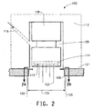
- Fig. 1 there is depicted a conventional spinning machine 10 with a spin pack 8 within a spin head, or spin beam, 12.
- a heated metallic plate 21 is attached to the bottom of the spin head.
- the spin pack body contains a spinneret plate 14 having a plurality of capillaries holes through which polymer is extruded.
- the molten polymer is extruded through the spinneret into multiple melt streams that are cooled in a quench zone 20 in any known manner to form filaments 22.
- Steam is supplied from an external source (not shown) through a channel 16 formed in the spin beam to an annular space 5 existing between the spin pack body 10 and the spin head 12 interior.
- the prior art spin pack and steam blanketing system of Fig. 1 suffers from poor air exclusion at the spinneret face 13. In this zone the freshly extruded polymeric filaments are most susceptible to degradation by atmospheric oxygen. The entrained air flow around the fast moving filaments draws the blanketing steam away from the spinneret plate and limits the steam effectiveness at excluding oxygen. As noted above with respect to Ferrier et al., if the steam blanketing is not completely effective, the entire spin pack must be periodically removed to keep the face of the spinneret free from deposits, which is expensive and disrupts production.
- the present invention provides a device (100) for spinning filaments (122) from extruded molten polymer comprising;
- the present invention solves the problems of the prior art by providing a simple device attached to the spin head to more effectively contact the spinneret face with steam and to provide a concentrated steam atmosphere to the freshly emerging polymer filaments.
- the device of the present invention is particularly advantageous over the prior art in that it does not require the replacement of a spin pack to keep the face of the spinneret free of hardened polymer deposits, but rather provides easy access to the spinneret fact so that it can be readily cleaned. Although wiping the face of the spinneret requires down time, replacing the spin pack requires even more down time. Thus, since the spin pack in a spinning system does not have to be replaced when the step distribution ring of the present invention is used, the present invention improves spinning systems by reducing process down time as compared to commercially available equipment.
- the apparatus of the present invention does not require substantial modification of existing equipment.
- the steam distribution ring of the present invention is easy and inexpensive to fabricate.
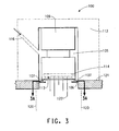
- a device for spinning filaments from extruded molten polymer is shown generally at 100 in Fig. 2 .
- the system comprises a spinneret pack body 108 including a spinneret plate 114 having a lower face 113 through with an array of extrusion capillaries (not shown) through which polymer is extruded.
- the molten polymer is extruded through the spinneret into multiple melt streams that are cooled in a quench zone 120 in any known manner to form filaments 122.
- the device of the present invention further includes a spin head surrounding the spinneret pack body.
- a spin head is shown at 112 in Fig. 2 .
- a metallic plate 121 is located at the bottom of the spin head on both sides of the spin pack. Preferably the metallic plate is heated by any known means including thermal contact with the.heated spin head.
- the present invention also includes a steam distribution ring surrounding the filament array.
- a steam distribution ring is shown at 109 in Fig. 2 .
- the steam distribution ring is located below the spin pack and close to the face of the spinneret.
- the steam distribution ring of the present invention abuts the spin head.
- the ring is removably mounted to the spin head.
- the steam distribution ring of the present invention may be removably mounted by an interference fit within a counterbore of diameter 123 formed in plate 121 and centered on the spinneret face.
- the emerging filaments 122 pass through an opening in the steam distribution ring 109 concentric with the counterbore of the metallic plate.
- the steam distribution ring of the embodiment of Fig. 2 includes a skirt portion 109', as shown in Pigs. 2A and 2B.
- the skirt portion is generally perpendicular to the distribution ring and when mounted in the spin pack perpendicular to the spinneret plate face.
- the ring can be retained solely by frictional forces (interference) within the counterbore of plate 121.
- One skilled in the art would know how the choice of diameter 109" is to be made once the diameter of the counterbore in plate 121 is fixed.
- a flaring tool may be used to lock the steam distribution ring in the counterbore.
- FIGs. 3 and 3A another embodiment of the present invention is illustrated in a cross sectional view of a spin head and spin pack, with elements like those in Fig. 2 being shown with the same reference numerals.
- a steam distribution ring 106 as shown in planar view in Fig. 3A may be constructed to include one or more magnets 107 which attach magnetically to the spin head near the face 113 of the spinneret 114.
- a fully magnetized material may also be used as the steam distribution ring, thus creating a continuous magnet.
- the common feature of any of the above embodiments is that the steam distribution ring is removably mounted to the spin head, and the spinneret face is easily accessible, so that the spinneret face can be wiped clean, obviating the need for replacing a spin pack, which can be expensive.
- a method for keeping the face of a spinneret free of polymer deposits comprises the steps of removing a steam distribution ring which is removably mounted to a spin head and wiping the polymer deposits from the face of the spinneret. The steam distribution ring is removed without the need for replacing the spin pack.
- the steam distribution ring may be constructed from any suitable material, such as a metal, for example, aluminum, steel, or titanium, fused silica, ceramics, sapphire or quartz.
- a metal for example, aluminum, steel, or titanium, fused silica, ceramics, sapphire or quartz.
- the steam distribution ring is made of aluminum, which has a high coefficient of thermal expansion so that it expands to fit in the counterbore.
- the apparatus of the present invention may further include a valve on a steam blanketing supply line so that the steam can be shut off on the position being wiped.
- the shut-off valve is preferably a solenoid valve connected to an electrical switch located in closely to the spin head. Such preferred location of the electrical switch allows an operator to shut off the steam flow immediately before wiping the face of the spinneret plate.
- the electrical switch may preferably have a built-in timer function that will facilitate re-starting the steam flow after a predetermined amount of time. This will prevent the steam flow from being shut down for extended periods of time, which would lead to condensate forming in the supply line.
- Any gas can be used to blanket the face of the spinneret. Steam is preferred for blanketing freshly extruded polymeric filaments. Inert gases like nitrogen, argon, helium and their mixtures can provide benefits similar to steam as long as the oxygen content is very low.
- the present invention is especially useful for steam blanketing volumes above 0.289 kg/hour/spinneret, and preferably above 0.400 kg/hour/spinneret.
- Polyamides suitable for use in this invention include synthetic melt spinnable polyamide materials having recurring amide groups (-CO-NH-) as an integral part of the polymer chain.
- polyamide refers to polyamide homopolymers, copolymers, and mixtures thereof.
- Suitable polyamides that can be used in accordance with the invention include poly(hexamethylene adipamide) (i.e., nylon 6,6) homopolymer, poly(e-caproamide) (i.e., nylon 6) homopolymer, polydodecanolactam (i.e., nylon 12) homopolymer, poly(tetramethyleneadipamide) (i.e., nylon 4,6) homopolymer, poly(hexamethylene sebacamide) (i.e., nylon 6,10) homopolymer, the polyamide of n-dodecanedioic acid and hexamethylenediamine (i.e., nylon 6,12) homopolymer, the polyamide of dodecamethylenediamine and n-dodecanedioic acid (i.e., nylon 12,12) homopolymer, copolymers thereof, and mixtures thereof.
- poly(hexamethylene adipamide) i.e., nylon 6,6) homopolymer,
- Illustrative polyamides include copolymers made from a dicarboxylic acid component, such as terephthalic acid, isophthalic acid, adipic acid or sebacic acid, and a diamine component, such as hexamethylenediamine, 2-methylpentamethylenediamine, or 1,4-bis(aminomethyl)cylcohexane.
- a dicarboxylic acid component such as terephthalic acid, isophthalic acid, adipic acid or sebacic acid
- a diamine component such as hexamethylenediamine, 2-methylpentamethylenediamine, or 1,4-bis(aminomethyl)cylcohexane.
- polyamides as described above can be used alone or mixed in any desired amount with other polymer synthetic fibers such as spandex, polyester and natural fibers like cotton, silk, wool or other typical companion fibers to nylon.
- the present invention is not confined to polyamide filaments, but may be applied to other melt-spinnable polymers, including polyester, polyolefins, e.g., polypropylene and polyethylene.
- the polymers include copolymers, mixed polymers, blends, and chain-branched polymers, just as a few examples.
- filament is used generically, and does not necessarily exclude cut fibers (often referred to as staple), although synthetic polymers are generally prepared initially in the form of continuous polymeric filaments as they are melt-spun (extruded).
- the invention will now be exemplified by the following non-limiting examples.
- the steam distribution ring was mounted on a conventional spinning machine, such as described in U.S. Patent No. 5,750,215 (Steele et al. ).
- Tenacity (Ten) is measured in grams (force) per yarn denier and elongation (E) is in percent.
- Grams of force are equal to force in Newtons divided by 102 (grams per Nawton).
- Denier is equal to linear density in decitex multiplied by 9/10 (denier per decitex).
- Tenacity and elongation of the yarn are used to show the superior properties provided to the product by the use of the steam blanketing distribution ring. They are measured according to ASTM D2256 using a 10 in (25.4 cm) gauge length sample, at 65% RH and 21°C (70 degrees F.), at an elongation rate of 60% per min. Elongation to break is measured according to ASTM D955.
- quality index is defined to be the square root of the quantity percent elongation multiplied by tenacity.
- quality index % elongation ⁇ tenacity ( grams / denier ) 1 / 2
- a "bent filament” metric (a direct count of bent filaments versus the total number of filaments per spinneret expressed as per cent) is used to evaluate the performance of the steam distribution ring. Additionally, a wipe cycle is defined as the time between spinneret wipes (equivalent to "wipe life” and expressed in hours). Wipes are required to renew the spinneret surface after some period of filament spinning. Wipe life, a comparison of wipe cycle performance of a conventional steam blanketing system to that of a system modified with the invention is another measure of performance for the invention.
- Example 1 compares a spinning machine which includes a steam blanketing distribution ring according to the embodiment of Fig. 2 of the present invention versus a conventional spinning machine without steam blanketing and with prior art spinneret steam blanketing, provided as shown in Fig. 1 herein.
- the distribution ring used in this Example had dimensions of 91 mm (outside diameter 109" in Fig. 2B ) and 70 mm for the aperture (diameter 109''' in Fig. 2B ).
- the polymer in this example was nylon 66 with an initial formic acid relative viscosity of between 53 and 58.
- the polymer contained titanium dioxide delusterant at a concentration of 0.3% by weight.
- bent filaments started to appear after only 4 hours of operation with more than 10% of the filaments being affected after 5 to 6 hours of operation.
- bent filaments started to appear after 5 to 6 hours of operation with more than 10% of the filaments being affected after 6 to 7 hours of operation.
- This Example was performed according to Example 1, and with the steam distribution ring of the present invention.
- This Example shows that the use of the steam distribution ring of the present invention with spinneret steam blanketing results in an increase in tenacity and elongation in the filaments compared to the use of spinneret steam blanketing without the steam ring. This resulted in an improvement in quality, Q, of the yarn through the use of the steam distribution ring.
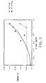
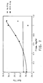
- Figs. 5 , 6 , and 7 The data obtained in Examples 1 and 2 are compared in three ways shown in Figs. 5 , 6 , and 7 .
- Fig. 5 the yarn tenacity is plotted versus the steam flow to the steam blanketing system. In every case where the steam distribution ring was used, and steam was flowing to the steam blanketing system, the yarn tenacity was superior to that of the control.
- Fig. 6 the yarn elongation to break is plotted versus the steam flow to the steam blanketing system. In cases where the steam distribution ring was used and steam was flowing to the steam blanketing system, the yarn elongation to break was superior to that of the control.
- Fig. 6 the yarn elongation to break was superior to that of the control.
- Fig. 7 the quality of the yarn (as defined in the equation above) is plotted versus the steam flow to the steam blanketing system. Quality is a geometric mean of significant yarn performance-in-use parameters.
- Fig. 7 shows quality versus steam flow to the steam blanketing system. In Fig. 7 quality was shown to be superior (higher) for each measurement where the steam distribution ring was used and steam was flowing to the steam blanketing system.
Landscapes
- Engineering & Computer Science (AREA)
- Mechanical Engineering (AREA)
- Textile Engineering (AREA)
- Spinning Methods And Devices For Manufacturing Artificial Fibers (AREA)
- Artificial Filaments (AREA)
Claims (1)
- Vorrichtung (100) zum Spinnen von Filamenten (122) aus extrudiertem geschmolzenem Polymer, die Folgendes umfasst:ein Spinndüsen-Verpackungsgehäuse (108), das eine Spinndüsenplatte (114) einschließt, die eine untere Fläche (113) hat, die eine Anordnung von Kapillarlöchern hat, durch die Polymer in mehrere Schmelzströme extrudiert wird,eine Abkühlzone (120), in der die mehreren Schmelzströme gekühlt werden, um Filamente (122) zu bilden,einen Spinnkopf (112), der das Spinndüsen-Verpackungsgehäuse (108) umschließt,eine Metallplatte (121), die am Unterteil des Spinnkopfes (112) auf beiden Seiten des Spinndüsen-Verpackungsgehäuses (108) angeordnet ist,einen Kanal (116), der in dem Spinnkopf (112) geformt ist, um ein Gas, ausgewählt aus Dampf und einem inerten Gas, das einen sehr niedrigen Sauerstoffgehalt hat, einem ringförmigen Raum (105) zuzuführen, der zwischen dem Spinndüsen-Verpackungsgehäuse (108) und dem Inneren des Spinnkopfes (112) vorhanden ist,dadurch gekennzeichnet, dass die Vorrichtung zusätzlich einen Dampfverteilungsring (109/106) umfasst, wobei der Dampfverteilungsring unterhalb des Spinndüsen-Verpackungsgehäuses (108) anstoßend an den Spinnkopf (112) angeordnet ist, wobei der Dampfverteilungsring (109/106) an dem Spinnkopf (112) befestigt ist und wobei der Dampfverteilungsring (109/106) zum Zweck einer Spinndüsen-Oberflächenreinigung abnehmbar an dem Spinnkopf (112) angebracht ist, durch ein Mittel, daraus ausgewählt, dass (a) der Dampfverteilungsring (109) nur durch Reibungskräfte durch eine Presspassung innerhalb einer Senkung gehalten wird, die in der Metallplatte (121) bereitgestellt wird; (b) der Dampfverteilungsring (106) einen oder mehrere Magneten (107) einschließt, die sich nahe der Fläche (113) der Spinndüsenplatte (114) an dem Spinnkopf (112) befestigen; und (c) der Dampfverteilungsring (106) aus einem magnetisierten Material hergestellt ist.
Applications Claiming Priority (3)
| Application Number | Priority Date | Filing Date | Title |
|---|---|---|---|
| US21352300P | 2000-06-23 | 2000-06-23 | |
| US213523P | 2000-06-23 | ||
| PCT/US2001/019701 WO2002000972A1 (en) | 2000-06-23 | 2001-06-20 | Steam distribution ring for spinning machines |
Publications (2)
| Publication Number | Publication Date |
|---|---|
| EP1297201A1 EP1297201A1 (de) | 2003-04-02 |
| EP1297201B1 true EP1297201B1 (de) | 2008-07-30 |
Family
ID=22795427
Family Applications (1)
| Application Number | Title | Priority Date | Filing Date |
|---|---|---|---|
| EP01948521A Expired - Lifetime EP1297201B1 (de) | 2000-06-23 | 2001-06-20 | Spinnvorrichtung enthaltend Spinndüse mit Dampfverteilungsring |
Country Status (14)
| Country | Link |
|---|---|
| US (1) | US6926508B2 (de) |
| EP (1) | EP1297201B1 (de) |
| JP (1) | JP2004502043A (de) |
| KR (1) | KR100732097B1 (de) |
| CN (1) | CN1328419C (de) |
| AU (1) | AU2001269955A1 (de) |
| BR (1) | BR0111840A (de) |
| CA (1) | CA2410415A1 (de) |
| DE (1) | DE60135122D1 (de) |
| ES (1) | ES2310556T3 (de) |
| MX (1) | MXPA02012724A (de) |
| TW (1) | TW575700B (de) |
| WO (1) | WO2002000972A1 (de) |
| ZA (1) | ZA200209401B (de) |
Families Citing this family (21)
| Publication number | Priority date | Publication date | Assignee | Title |
|---|---|---|---|---|
| EP1744751A4 (de) * | 2004-03-18 | 2010-03-10 | Brigham & Womens Hospital | Verfahren zur behandlung von synucleinopathien |
| CA2559221A1 (en) * | 2004-03-18 | 2005-09-29 | Brigham And Women's Hospital, Inc. | Methods for the treatment of synucleinopathies |
| US20050272068A1 (en) * | 2004-03-18 | 2005-12-08 | The Brigham And Women's Hospital, Inc. | UCH-L1 expression and cancer therapy |
| CA2559282A1 (en) * | 2004-03-18 | 2005-09-29 | Brigham And Women's Hospital, Inc. | Methods for the treatment of synucleinopathies |
| WO2005089515A2 (en) * | 2004-03-18 | 2005-09-29 | The Brigham And Women's Hospital, Inc. | Methods for the treatment of synucleinopathies |
| US20070293539A1 (en) * | 2004-03-18 | 2007-12-20 | Lansbury Peter T | Methods for the treatment of synucleinopathies |
| US20060194821A1 (en) * | 2005-02-18 | 2006-08-31 | The Brigham And Women's Hospital, Inc. | Compounds inhibiting the aggregation of superoxide dismutase-1 |
| WO2009151683A2 (en) * | 2008-03-12 | 2009-12-17 | Link Medicine Corporation | Quinolinone farnesyl transferase inhibitors for the treatment of synucleinopathies and other indications |
| US20100331363A1 (en) * | 2008-11-13 | 2010-12-30 | Link Medicine Corporation | Treatment of mitochondrial disorders using a farnesyl transferase inhibitor |
| AU2009313927A1 (en) * | 2008-11-13 | 2010-05-20 | Astrazeneca Ab | Azaquinolinone derivatives and uses thereof |
| US20110060005A1 (en) * | 2008-11-13 | 2011-03-10 | Link Medicine Corporation | Treatment of mitochondrial disorders using a farnesyl transferase inhibitor |
| US9570845B2 (en) | 2009-05-22 | 2017-02-14 | Ppc Broadband, Inc. | Connector having a continuity member operable in a radial direction |
| US8287320B2 (en) | 2009-05-22 | 2012-10-16 | John Mezzalingua Associates, Inc. | Coaxial cable connector having electrical continuity member |
| US8337229B2 (en) | 2010-11-11 | 2012-12-25 | John Mezzalingua Associates, Inc. | Connector having a nut-body continuity element and method of use thereof |
| US8366481B2 (en) | 2011-03-30 | 2013-02-05 | John Mezzalingua Associates, Inc. | Continuity maintaining biasing member |
| US9711917B2 (en) | 2011-05-26 | 2017-07-18 | Ppc Broadband, Inc. | Band spring continuity member for coaxial cable connector |
| US9203167B2 (en) | 2011-05-26 | 2015-12-01 | Ppc Broadband, Inc. | Coaxial cable connector with conductive seal |
| CN107034530B (zh) * | 2017-04-28 | 2023-12-26 | 北京中丽制机工程技术有限公司 | 一种蒸汽喷射装置 |
| CN110733932B (zh) * | 2018-07-19 | 2022-12-16 | 欧瑞康纺织有限及两合公司 | 一种熔体纺丝和卷绕纱线的方法 |
| EP3674452A1 (de) | 2018-12-28 | 2020-07-01 | Lenzing Aktiengesellschaft | Spinndüse, verfahren zur erwärmung einer spinndüse und lyocellprozess |
| EP3969643B1 (de) * | 2019-05-17 | 2023-11-15 | Lenzing Aktiengesellschaft | Verfahren und vorrichtung zur düsenreinigung während der herstellung von cellulosischem spinnvlies |
Family Cites Families (15)
| Publication number | Priority date | Publication date | Assignee | Title |
|---|---|---|---|---|
| US2252689A (en) * | 1938-03-10 | 1941-08-19 | Du Pont | Production of filaments, ribbons, and the like |
| GB901398A (en) * | 1960-05-19 | 1962-07-18 | British Nylon Spinners Ltd | Improvements in or relating to melt-spinning synthetic polymer filaments |
| US3229330A (en) * | 1964-01-24 | 1966-01-18 | British Nylon Spinners Ltd | Apparatus for melt-spinning synthetic polymer filaments |
| US3242529A (en) * | 1963-01-25 | 1966-03-29 | British Nylon Spinners Ltd | Melt-spinning apparatus with oppositely directed inert gas streams |
| US3398429A (en) * | 1966-10-10 | 1968-08-27 | Du Pont | Spinneret enclosure |
| US3672800A (en) * | 1970-07-01 | 1972-06-27 | Du Pont | Galvanic detection of oxygen in a spinning cell steam chamber |
| US3761559A (en) * | 1972-04-24 | 1973-09-25 | Du Pont | Opposed flow spinneret blanketer |
| US3814559A (en) | 1972-10-27 | 1974-06-04 | Du Pont | Spinneret with inert gas metering ring |
| US3907957A (en) * | 1973-06-18 | 1975-09-23 | Du Pont | Quenching process for melt extruded filaments |
| US3975475A (en) * | 1974-12-17 | 1976-08-17 | E. I. Du Pont De Nemours And Company | Wiping spinneret face with cooled wiper |
| US4462229A (en) | 1981-11-19 | 1984-07-31 | Imperial Chemical Industries Plc | Closeable threadline guide for suppressing fluid flow |
| JPS61102407A (ja) * | 1984-10-19 | 1986-05-21 | Asahi Chem Ind Co Ltd | 溶融紡糸装置 |
| US5558826A (en) | 1995-02-07 | 1996-09-24 | E. I. Du Pont De Nemours And Company | High speed process for making fully-oriented nylon yarns |
| DE59608283D1 (de) | 1995-02-10 | 2002-01-10 | Barmag Barmer Maschf | Verfahren zur Herstellung eines multifilen Fadens |
| DE19830453A1 (de) * | 1998-07-08 | 2000-01-13 | Lurgi Zimmer Ag | Verfahren und Vorrichtung zum Transport von Dampf durch mindestens einen runden Spinndüsenschacht |
-
2001
- 2001-06-20 EP EP01948521A patent/EP1297201B1/de not_active Expired - Lifetime
- 2001-06-20 ES ES01948521T patent/ES2310556T3/es not_active Expired - Lifetime
- 2001-06-20 CN CNB018116566A patent/CN1328419C/zh not_active Expired - Fee Related
- 2001-06-20 KR KR1020027017480A patent/KR100732097B1/ko not_active Expired - Fee Related
- 2001-06-20 AU AU2001269955A patent/AU2001269955A1/en not_active Abandoned
- 2001-06-20 CA CA002410415A patent/CA2410415A1/en not_active Abandoned
- 2001-06-20 JP JP2002506277A patent/JP2004502043A/ja not_active Withdrawn
- 2001-06-20 BR BR0111840-4A patent/BR0111840A/pt active Search and Examination
- 2001-06-20 DE DE60135122T patent/DE60135122D1/de not_active Expired - Fee Related
- 2001-06-20 WO PCT/US2001/019701 patent/WO2002000972A1/en not_active Ceased
- 2001-06-20 MX MXPA02012724A patent/MXPA02012724A/es active IP Right Grant
- 2001-06-21 TW TW90115143A patent/TW575700B/zh not_active IP Right Cessation
- 2001-06-21 US US09/886,073 patent/US6926508B2/en not_active Expired - Fee Related
-
2002
- 2002-11-19 ZA ZA200209401A patent/ZA200209401B/en unknown
Also Published As
| Publication number | Publication date |
|---|---|
| WO2002000972A1 (en) | 2002-01-03 |
| TW575700B (en) | 2004-02-11 |
| US20020043733A1 (en) | 2002-04-18 |
| CN1328419C (zh) | 2007-07-25 |
| ES2310556T3 (es) | 2009-01-16 |
| US6926508B2 (en) | 2005-08-09 |
| MXPA02012724A (es) | 2003-05-14 |
| CA2410415A1 (en) | 2002-01-03 |
| KR20030020305A (ko) | 2003-03-08 |
| AU2001269955A1 (en) | 2002-01-08 |
| BR0111840A (pt) | 2003-07-01 |
| ZA200209401B (en) | 2003-11-19 |
| DE60135122D1 (de) | 2008-09-11 |
| KR100732097B1 (ko) | 2007-06-27 |
| CN1437662A (zh) | 2003-08-20 |
| JP2004502043A (ja) | 2004-01-22 |
| EP1297201A1 (de) | 2003-04-02 |
Similar Documents
| Publication | Publication Date | Title |
|---|---|---|
| EP1297201B1 (de) | Spinnvorrichtung enthaltend Spinndüse mit Dampfverteilungsring | |
| MXPA02012658A (es) | Metodo de tratamiento de sustratos minerales. | |
| US6284174B1 (en) | Melt spinning pack and synthetic fiber manufacturing method | |
| US3129272A (en) | Melt-spinning synthetic polymer filaments | |
| US3975475A (en) | Wiping spinneret face with cooled wiper | |
| EP1951936A1 (de) | Verfahren und vorrichtung zum schmelzspinnen und abkühlen eines multifilen fadens mit kühllufttemperaturmessung innerhalb des filamentbündels | |
| US6033609A (en) | Device and method to prevent spinneret hole contamination | |
| US3229330A (en) | Apparatus for melt-spinning synthetic polymer filaments | |
| EP0370816A2 (de) | Verfahren zur Herstellung von Polyesterfilamenten | |
| JP2010077570A (ja) | 溶融紡糸方法および溶融紡糸装置 | |
| JP3967260B2 (ja) | 溶融紡糸装置、及びこれを用いた長繊維不織布の製造方法 | |
| JP6701822B2 (ja) | 溶融紡糸用パック | |
| JP2003138464A (ja) | 長繊維不織布の溶融紡糸装置、及びこれを用いた製造方法 | |
| US3669584A (en) | Melt-spinning apparatus | |
| JP2000314031A (ja) | 高強力ポリエステル繊維の製造方法 | |
| JP2838042B2 (ja) | 多孔紡糸口金及びこの紡糸口金を用いた極細マルチフィラメント糸の溶融紡糸方法 | |
| JP2734699B2 (ja) | 多フィラメント用紡糸口金 | |
| JP3820001B2 (ja) | ポリマー分配板 | |
| EP1529856B1 (de) | Spinndüse zur Herstellung von Garnen mit kreisförmigem Querschnitt und Verfahren zu deren Herstellung | |
| EP4141153A1 (de) | Polyamid-monofilament | |
| JP5262038B2 (ja) | 熱可塑性繊維の製造方法およびその製造装置 | |
| JP2707889B2 (ja) | 紡糸用スピンパック | |
| JP2007126759A (ja) | 極細ポリアミド繊維の溶融紡糸方法 | |
| JP2006348408A (ja) | 溶融紡糸装置 | |
| JPH05171506A (ja) | 多孔紡糸口金 |
Legal Events
| Date | Code | Title | Description |
|---|---|---|---|
| PUAI | Public reference made under article 153(3) epc to a published international application that has entered the european phase |
Free format text: ORIGINAL CODE: 0009012 |
|
| 17P | Request for examination filed |
Effective date: 20021206 |
|
| AK | Designated contracting states |
Kind code of ref document: A1 Designated state(s): AT BE CH CY DE DK ES FI FR GB GR IE IT LI LU MC NL PT SE TR Designated state(s): AT BE CH CY DE DK ES FI FR GB GR IE IT LI LU MC NL PT SE TR |
|
| AX | Request for extension of the european patent |
Extension state: AL LT LV MK RO SI |
|
| RBV | Designated contracting states (corrected) |
Designated state(s): AT BE CH CY DE ES FR GB LI |
|
| RAP1 | Party data changed (applicant data changed or rights of an application transferred) |
Owner name: INVISTA TECHNOLOGIES S.AE.R.L. |
|
| 111Z | Information provided on other rights and legal means of execution |
Free format text: ATBECHCYDEESFRGBLI Effective date: 20040731 |
|
| RAP1 | Party data changed (applicant data changed or rights of an application transferred) |
Owner name: INVISTA TECHNOLOGIES S.AE.R.L. |
|
| 17Q | First examination report despatched |
Effective date: 20050207 |
|
| RTI1 | Title (correction) |
Free format text: SPINNING MACHINE COMPRISING SPINNERET WITH STEAM DISTRIBUTION RING |
|
| GRAP | Despatch of communication of intention to grant a patent |
Free format text: ORIGINAL CODE: EPIDOSNIGR1 |
|
| RAP1 | Party data changed (applicant data changed or rights of an application transferred) |
Owner name: INVISTA TECHNOLOGIES S.A.R.L. |
|
| RBV | Designated contracting states (corrected) |
Designated state(s): CH DE ES FR GB LI |
|
| GRAS | Grant fee paid |
Free format text: ORIGINAL CODE: EPIDOSNIGR3 |
|
| GRAA | (expected) grant |
Free format text: ORIGINAL CODE: 0009210 |
|
| AK | Designated contracting states |
Kind code of ref document: B1 Designated state(s): CH DE ES FR GB LI |
|
| REG | Reference to a national code |
Ref country code: GB Ref legal event code: FG4D |
|
| REG | Reference to a national code |
Ref country code: CH Ref legal event code: EP |
|
| REG | Reference to a national code |
Ref country code: CH Ref legal event code: NV Representative=s name: RITSCHER & PARTNER AG |
|
| REF | Corresponds to: |
Ref document number: 60135122 Country of ref document: DE Date of ref document: 20080911 Kind code of ref document: P |
|
| REG | Reference to a national code |
Ref country code: ES Ref legal event code: FG2A Ref document number: 2310556 Country of ref document: ES Kind code of ref document: T3 |
|
| REG | Reference to a national code |
Ref country code: GB Ref legal event code: 732E Free format text: REGISTERED BETWEEN 20090507 AND 20090513 |
|
| PLBE | No opposition filed within time limit |
Free format text: ORIGINAL CODE: 0009261 |
|
| STAA | Information on the status of an ep patent application or granted ep patent |
Free format text: STATUS: NO OPPOSITION FILED WITHIN TIME LIMIT |
|
| 26N | No opposition filed |
Effective date: 20090506 |
|
| PGFP | Annual fee paid to national office [announced via postgrant information from national office to epo] |
Ref country code: ES Payment date: 20090709 Year of fee payment: 9 Ref country code: CH Payment date: 20090615 Year of fee payment: 9 |
|
| PGFP | Annual fee paid to national office [announced via postgrant information from national office to epo] |
Ref country code: GB Payment date: 20090617 Year of fee payment: 9 Ref country code: DE Payment date: 20090619 Year of fee payment: 9 |
|
| REG | Reference to a national code |
Ref country code: CH Ref legal event code: PL |
|
| GBPC | Gb: european patent ceased through non-payment of renewal fee |
Effective date: 20100620 |
|
| REG | Reference to a national code |
Ref country code: FR Ref legal event code: ST Effective date: 20110228 |
|
| PG25 | Lapsed in a contracting state [announced via postgrant information from national office to epo] |
Ref country code: CH Free format text: LAPSE BECAUSE OF NON-PAYMENT OF DUE FEES Effective date: 20100630 Ref country code: DE Free format text: LAPSE BECAUSE OF NON-PAYMENT OF DUE FEES Effective date: 20110101 Ref country code: LI Free format text: LAPSE BECAUSE OF NON-PAYMENT OF DUE FEES Effective date: 20100630 |
|
| PG25 | Lapsed in a contracting state [announced via postgrant information from national office to epo] |
Ref country code: FR Free format text: LAPSE BECAUSE OF NON-PAYMENT OF DUE FEES Effective date: 20100630 |
|
| REG | Reference to a national code |
Ref country code: ES Ref legal event code: FD2A Effective date: 20110714 |
|
| PG25 | Lapsed in a contracting state [announced via postgrant information from national office to epo] |
Ref country code: GB Free format text: LAPSE BECAUSE OF NON-PAYMENT OF DUE FEES Effective date: 20100620 Ref country code: ES Free format text: LAPSE BECAUSE OF NON-PAYMENT OF DUE FEES Effective date: 20110704 |
|
| PG25 | Lapsed in a contracting state [announced via postgrant information from national office to epo] |
Ref country code: ES Free format text: LAPSE BECAUSE OF NON-PAYMENT OF DUE FEES Effective date: 20100621 |
|
| PGFP | Annual fee paid to national office [announced via postgrant information from national office to epo] |
Ref country code: FR Payment date: 20090611 Year of fee payment: 9 |