EP1296120A2 - Verfahren zur Bestimmung von Kraftstoffverbrauchswerten und Steuergerät für eine Brennkraftmaschine - Google Patents
Verfahren zur Bestimmung von Kraftstoffverbrauchswerten und Steuergerät für eine Brennkraftmaschine Download PDFInfo
- Publication number
- EP1296120A2 EP1296120A2 EP02016723A EP02016723A EP1296120A2 EP 1296120 A2 EP1296120 A2 EP 1296120A2 EP 02016723 A EP02016723 A EP 02016723A EP 02016723 A EP02016723 A EP 02016723A EP 1296120 A2 EP1296120 A2 EP 1296120A2
- Authority
- EP
- European Patent Office
- Prior art keywords
- fuel
- internal combustion
- fuel consumption
- combustion engine
- motor vehicle
- Prior art date
- Legal status (The legal status is an assumption and is not a legal conclusion. Google has not performed a legal analysis and makes no representation as to the accuracy of the status listed.)
- Withdrawn
Links
- 239000000446 fuel Substances 0.000 title claims abstract description 113
- 238000002485 combustion reaction Methods 0.000 title claims abstract description 54
- 238000000034 method Methods 0.000 title claims abstract description 38
- 238000004590 computer program Methods 0.000 claims abstract description 11
- MWUXSHHQAYIFBG-UHFFFAOYSA-N Nitric oxide Chemical compound O=[N] MWUXSHHQAYIFBG-UHFFFAOYSA-N 0.000 claims description 18
- 238000002347 injection Methods 0.000 claims description 14
- 239000007924 injection Substances 0.000 claims description 14
- 239000003054 catalyst Substances 0.000 claims description 13
- 239000000203 mixture Substances 0.000 claims description 8
- 238000007906 compression Methods 0.000 claims description 7
- 230000006835 compression Effects 0.000 claims description 7
- 238000004140 cleaning Methods 0.000 claims description 6
- 230000001419 dependent effect Effects 0.000 claims description 4
- 230000003287 optical effect Effects 0.000 claims description 2
- 230000001960 triggered effect Effects 0.000 claims description 2
- 230000006698 induction Effects 0.000 claims 1
- 239000002245 particle Substances 0.000 claims 1
- 239000002828 fuel tank Substances 0.000 abstract 1
- 230000000007 visual effect Effects 0.000 abstract 1
- 230000003197 catalytic effect Effects 0.000 description 7
- QVGXLLKOCUKJST-UHFFFAOYSA-N atomic oxygen Chemical compound [O] QVGXLLKOCUKJST-UHFFFAOYSA-N 0.000 description 6
- 238000004364 calculation method Methods 0.000 description 6
- 239000001301 oxygen Substances 0.000 description 6
- 229910052760 oxygen Inorganic materials 0.000 description 6
- 238000011161 development Methods 0.000 description 5
- 230000018109 developmental process Effects 0.000 description 5
- 239000007789 gas Substances 0.000 description 5
- 238000010304 firing Methods 0.000 description 4
- 230000009286 beneficial effect Effects 0.000 description 2
- 238000010438 heat treatment Methods 0.000 description 2
- 102000018658 Myotonin-Protein Kinase Human genes 0.000 description 1
- 108010052185 Myotonin-Protein Kinase Proteins 0.000 description 1
- NINIDFKCEFEMDL-UHFFFAOYSA-N Sulfur Chemical compound [S] NINIDFKCEFEMDL-UHFFFAOYSA-N 0.000 description 1
- 230000001133 acceleration Effects 0.000 description 1
- 238000013459 approach Methods 0.000 description 1
- 238000012937 correction Methods 0.000 description 1
- 230000006866 deterioration Effects 0.000 description 1
- 239000003344 environmental pollutant Substances 0.000 description 1
- 238000009472 formulation Methods 0.000 description 1
- 230000010354 integration Effects 0.000 description 1
- 230000003647 oxidation Effects 0.000 description 1
- 238000007254 oxidation reaction Methods 0.000 description 1
- 231100000719 pollutant Toxicity 0.000 description 1
- 230000008929 regeneration Effects 0.000 description 1
- 238000011069 regeneration method Methods 0.000 description 1
- 230000001105 regulatory effect Effects 0.000 description 1
- 239000000126 substance Substances 0.000 description 1
- 229910052717 sulfur Inorganic materials 0.000 description 1
- 239000011593 sulfur Substances 0.000 description 1
- 238000012546 transfer Methods 0.000 description 1
- 238000010792 warming Methods 0.000 description 1
Images

Classifications
-
- G—PHYSICS
- G01—MEASURING; TESTING
- G01F—MEASURING VOLUME, VOLUME FLOW, MASS FLOW OR LIQUID LEVEL; METERING BY VOLUME
- G01F9/00—Measuring volume flow relative to another variable, e.g. of liquid fuel for an engine
- G01F9/008—Measuring volume flow relative to another variable, e.g. of liquid fuel for an engine where the other variable is the flight or running time
-
- G—PHYSICS
- G01—MEASURING; TESTING
- G01F—MEASURING VOLUME, VOLUME FLOW, MASS FLOW OR LIQUID LEVEL; METERING BY VOLUME
- G01F9/00—Measuring volume flow relative to another variable, e.g. of liquid fuel for an engine
- G01F9/02—Measuring volume flow relative to another variable, e.g. of liquid fuel for an engine wherein the other variable is the speed of a vehicle
- G01F9/023—Measuring volume flow relative to another variable, e.g. of liquid fuel for an engine wherein the other variable is the speed of a vehicle with electric, electro-mechanic or electronic means
-
- F—MECHANICAL ENGINEERING; LIGHTING; HEATING; WEAPONS; BLASTING
- F02—COMBUSTION ENGINES; HOT-GAS OR COMBUSTION-PRODUCT ENGINE PLANTS
- F02D—CONTROLLING COMBUSTION ENGINES
- F02D41/00—Electrical control of supply of combustible mixture or its constituents
- F02D41/30—Controlling fuel injection
- F02D41/38—Controlling fuel injection of the high pressure type
- F02D2041/389—Controlling fuel injection of the high pressure type for injecting directly into the cylinder
-
- F—MECHANICAL ENGINEERING; LIGHTING; HEATING; WEAPONS; BLASTING
- F02—COMBUSTION ENGINES; HOT-GAS OR COMBUSTION-PRODUCT ENGINE PLANTS
- F02D—CONTROLLING COMBUSTION ENGINES
- F02D2200/00—Input parameters for engine control
- F02D2200/02—Input parameters for engine control the parameters being related to the engine
- F02D2200/06—Fuel or fuel supply system parameters
- F02D2200/0625—Fuel consumption, e.g. measured in fuel liters per 100 kms or miles per gallon
-
- F—MECHANICAL ENGINEERING; LIGHTING; HEATING; WEAPONS; BLASTING
- F02—COMBUSTION ENGINES; HOT-GAS OR COMBUSTION-PRODUCT ENGINE PLANTS
- F02D—CONTROLLING COMBUSTION ENGINES
- F02D41/00—Electrical control of supply of combustible mixture or its constituents
- F02D41/02—Circuit arrangements for generating control signals
- F02D41/021—Introducing corrections for particular conditions exterior to the engine
- F02D41/0235—Introducing corrections for particular conditions exterior to the engine in relation with the state of the exhaust gas treating apparatus
- F02D41/027—Introducing corrections for particular conditions exterior to the engine in relation with the state of the exhaust gas treating apparatus to purge or regenerate the exhaust gas treating apparatus
- F02D41/0275—Introducing corrections for particular conditions exterior to the engine in relation with the state of the exhaust gas treating apparatus to purge or regenerate the exhaust gas treating apparatus the exhaust gas treating apparatus being a NOx trap or adsorbent
-
- F—MECHANICAL ENGINEERING; LIGHTING; HEATING; WEAPONS; BLASTING
- F02—COMBUSTION ENGINES; HOT-GAS OR COMBUSTION-PRODUCT ENGINE PLANTS
- F02D—CONTROLLING COMBUSTION ENGINES
- F02D41/00—Electrical control of supply of combustible mixture or its constituents
- F02D41/02—Circuit arrangements for generating control signals
- F02D41/021—Introducing corrections for particular conditions exterior to the engine
- F02D41/0235—Introducing corrections for particular conditions exterior to the engine in relation with the state of the exhaust gas treating apparatus
- F02D41/027—Introducing corrections for particular conditions exterior to the engine in relation with the state of the exhaust gas treating apparatus to purge or regenerate the exhaust gas treating apparatus
- F02D41/029—Introducing corrections for particular conditions exterior to the engine in relation with the state of the exhaust gas treating apparatus to purge or regenerate the exhaust gas treating apparatus the exhaust gas treating apparatus being a particulate filter
-
- F—MECHANICAL ENGINEERING; LIGHTING; HEATING; WEAPONS; BLASTING
- F02—COMBUSTION ENGINES; HOT-GAS OR COMBUSTION-PRODUCT ENGINE PLANTS
- F02D—CONTROLLING COMBUSTION ENGINES
- F02D41/00—Electrical control of supply of combustible mixture or its constituents
- F02D41/30—Controlling fuel injection
- F02D41/3011—Controlling fuel injection according to or using specific or several modes of combustion
- F02D41/3017—Controlling fuel injection according to or using specific or several modes of combustion characterised by the mode(s) being used
- F02D41/3023—Controlling fuel injection according to or using specific or several modes of combustion characterised by the mode(s) being used a mode being the stratified charge spark-ignited mode
- F02D41/3029—Controlling fuel injection according to or using specific or several modes of combustion characterised by the mode(s) being used a mode being the stratified charge spark-ignited mode further comprising a homogeneous charge spark-ignited mode
-
- F—MECHANICAL ENGINEERING; LIGHTING; HEATING; WEAPONS; BLASTING
- F02—COMBUSTION ENGINES; HOT-GAS OR COMBUSTION-PRODUCT ENGINE PLANTS
- F02D—CONTROLLING COMBUSTION ENGINES
- F02D41/00—Electrical control of supply of combustible mixture or its constituents
- F02D41/30—Controlling fuel injection
- F02D41/38—Controlling fuel injection of the high pressure type
- F02D41/40—Controlling fuel injection of the high pressure type with means for controlling injection timing or duration
- F02D41/402—Multiple injections
- F02D41/405—Multiple injections with post injections
Definitions
- the invention relates to a method for determining Fuel consumption values for internal combustion engines from Motor vehicles, especially with direct injection Internal combustion engines, the internal combustion engine at least can be operated in two different operating modes.
- the invention further relates to a corresponding one Control unit for an internal combustion engine, a Computer program with program code means and a Computer program product with program code means.
- DE 32 45 546 A1 discloses a device for Determination of the current fuel consumption of Internal combustion engines.
- the certain Fuel consumption values are here on a Display device in the driver's field of vision Motor vehicle shown.
- the device for determination the current fuel consumption is based on im Control unit stored consumption maps that Fuel consumption values depending on load and include speed-dependent signals.
- According to the DE 32 45 546 A1 is before the display of the A correction of the values taken from consumption maps Values depending on acceleration and / or temperature-dependent values.
- DE 197 39 848 A1 is a direct injection Internal combustion engine for a motor vehicle known in Exhaust system with an oxidation catalyst and additional is equipped with a storage catalytic converter.
- the Internal combustion engine can in a first operating mode, the Shift operation, during which the fuel from one Injector valve during a by a piston compression phase directly into a combustion chamber is injected, operated, or in a second Operating mode, the homogeneous mode during which the fuel from the injector during one through the piston induced suction phase directly into the combustion chamber is injected.
- an internal combustion engine according to DE 197 39 848 A1 can have a different fuel consumption in shift operation than in homogeneous operation with the same load or with the same accelerator pedal position.
- this can cause the fuel consumption of the internal combustion engine to make a temporary jump (for approx. 1 to 2 seconds) during the cleaning of the storage catalytic converter.
- this vehicle additionally with a fuel consumption display according to the DE 32 45 546 A1, this temporary jump in fuel consumption is visible to the driver of the motor vehicle on the fuel consumption display.
- the procedure provides that the corrected Fuel consumption values at least on an optical one Display in the field of vision of a driver of the motor vehicle are displayed and / or to determine a Remaining range of the motor vehicle and / or for determination of a tank content of the motor vehicle are used.
- These developments are particularly advantageous Way a fuel consumption display in the field of vision of the Driver of the motor vehicle controlled such that in certain temporary operating situations Fuel consumption display does not jump. In particular when the specific, temporary operating situations not caused by the driver of the motor vehicle it is usually undesirable that the Fuel consumption display has a jump.
- the corrected Fuel consumption values advantageous for determining the Remaining range of the motor vehicle or to determine the Tank contents of the motor vehicle are used, as here a simple hiding of jumps in fuel consumption would lead to incorrect calculations.
- the method according to the invention provides that a real one Fuel consumption value with an operating mode dependent Factor is linked and that as a result the Linking by changing the operating mode generated fuel difference consumption value and a Fuel consumption value that is without the Change of operating mode would have resulted.
- the fuel difference consumption value is filtered over time, in particular linear, the filter being a Has filter time constant that is an order of magnitude above a duration of the duration of the determined, temporary Operating situation.
- the various operating modes advantageously comprise at least one homogeneous mode while the fuel at least in one by a moving piston induced suction phase injected into a combustion chamber and a stratified mode while the fuel at least in one by the moving piston caused compression phase in the combustion chamber is injected.
- the different operating modes can also be advantageous at least one post injection mode during which Fuel after compression ignition has already occurred are already in a combustion chamber Fuel air mixture is injected into the combustion chamber, include. This is the advantageous procedure for a diesel engine.
- the particular temporary ones are particularly advantageous Operating situations with both the petrol and the Diesel engine at least that Catalyst cleaning, causing a temporary change of Operating mode is triggered.
- a Gasoline engine is powered by the Catalyst regeneration a nitrogen oxide storage catalyst and in the case of a diesel engine Particulate filter cleaned.
- a control device for a Internal combustion engine, in particular a motor vehicle compared to the prior art in that Means for performing the steps described above inventive method are available. in this connection represents the control device that the inventive Carries out method, the invention.
- Realizations are of particular importance in the form of a computer program with program code means and in the form of a computer program product Program code means.
- the computer program according to the invention comprises program code means to complete all steps of the perform the inventive method if that Program on a computer, in particular a control device executed for an internal combustion engine of a motor vehicle becomes.
- the invention is represented by an in program stored in the control unit, so that this control unit provided with the program in the same
- the invention represents how the method for its Execution the program is suitable.
- the invention Computer program product has program code means that are stored on a computer-readable data medium in order to to carry out the method according to the invention if that Program product on a computer, especially one Control unit for an internal combustion engine Motor vehicle is running.
- the invention realized by a data carrier, so that the method according to the invention can be carried out if the program product or the data carrier in a control unit for an internal combustion engine in particular one Motor vehicle is integrated.
- a data carrier or as Computer program product can in particular be an electrical one Storage medium are used, for example Read-only memory (ROM), an EPROM or an electrical one Permanent storage, such as a CD-ROM or a DVD.
- the fuel consumption of a petrol engine can despite constant operating point (constant engine speed, constant indexed moment) short-term fluctuations subject to certain, temporary operating situations available.
- This can be the mixture enrichment for example Cleaning a storage catalytic converter at a direct-injection gasoline engine, as well like the torque reserve or the lambda split operating mode Clear sulfur out of the storage catalytic converter.
- a torque reserve is a torque amount, that by adjusting the ignition angle in the early direction can be called up suddenly. Since in homogeneous operation with stoichiometric mixture usually always the earliest possible or the optimal ignition angle is selected, this is not possible in this case. A torque reserve must therefore preparatory by increasing the filling and late adjustment the ignition (associated with a worsening of the Efficiency and thus almost sudden increase in current fuel consumption) can be set.
- Lambda split is a catalyst heating measure one cylinder bank fat and the other lean is operated. The exhaust gas flows are brought together and the chemical energy contained therein is in the catalyst free and thus leads to heating of the catalyst. This warming is required to desulfate make.
- the lambda split mode is also included a deterioration in efficiency and thus an increased Fuel consumption connected.
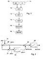
- the present invention replaces the previous consumption signal or the volume flow signal by a signal that does not contain this variation, but nevertheless leads to a correctly calculated consumption. For this the actual actual fuel consumption during the length of time during which the specific, temporary Operating situations exist with a dimensionless Factor F0 multiplied, in efficiency and air ratio come in, so that there is a fuel consumption that yourself without the specific, temporary operating situations would set. So that the integrated consumption signal remains correct, the time-filtered error is restored added. The detailed procedure for this is shown in the Figures 1 and 2.
- the first embodiment of the invention starts in a first step 10 with the determination of the real current Fuel mass flow MKP and determined in parallel in a step 11 a current dimensionless factor F0.
- the detailed determination of F0 will be discussed later received.
- the dimensionless factor is F0 equals 1 and takes for the period of the determined temporary operating situations to a value that is 1 differs.
- a step 12 of the procedure that follows following parallel steps 10 and 11 becomes the real one current fuel mass flow MKP with the dimensionless Factor F0 combined or multiplied, and you get as Result the fuel mass flow MKP0, which is without that Presence of the specific, temporary operating situation would result.
- the Fuel mass flow MKP0 which is without the presence of the certain, temporary operating situation would result from subtracted real fuel mass flow MKP and gives it as a result a differential fuel mass flow DMPK, due to the specific, temporary operating situations was caused.
- the previous one certain differential mass flow DMKP linearly filtered and it the linearly filtered results Differential fuel mass flow DMKPF.
- a linear filter is used to, as will be shown later, a correct overall Get fuel economy. wouldn't be the filter linear, an incorrect determination of the Total fuel consumption.
- Step 15 becomes the fuel mass flow MKP0, which is without the specific, temporary operating situations would, with the linearly filtered Differential fuel mass flow DMKPF summed up, and it there is a corrected according to the invention Fuel mass flow MKPKORR, for example, already on a display unit can be supplied. In one step Finally, the corrected fuel mass flow becomes 16 MKPKORR over the duration of the driving cycle TTRIP integrated, and there is a corrected MKKORR fuel consumption, almost the real one Fuel consumption corresponds to MK.
- the dimensionless factor F0 determined in step 11 can in the case of a direct injection internal combustion engine, the works according to the Otto principle, can be calculated as follows:
- MI0 K1 ⁇ RL0 ⁇ ETAZWBAS ⁇ ETALAM0
- the factor F01 is thus determined for the first case.
- the normal operating mode is an unthrottled operating mode (e.g. shift operation), so during the temporary Operating situation F01 used.
- the filter must be linear, then:
- FIG 2 shows the invention described in Figure 1 Process in a different representation:
- the signal of the current fuel mass flow MKP is one Multiplier 20 and a summation point 21 supplied.
- the Multiplier 20 is also the, as previously determined, dimensionless factor F0 supplied.
- the result of Multiplier 20 is the fuel mass flow MKP0, the yourself without the specific, temporary operating situations would result.
- the output signal of the multiplier 20 is the summation point 21 and the summation point 23 supplied.
- the current Fuel mass flow MKP the previously determined signal of the Fuel mass flow MKP0, which is without the determined, would result in temporary operating situations, subtracted and there is the differential fuel mass flow DMKP, which is characterized by the specific, temporary Operating situations.
- This signal DMKP is one linear filter 22 fed, which is a filter time constant has an order of magnitude over the period of The existence of certain temporary operating situations lies.
- the result of the filter 22 is the linearly filtered one Differential fuel mass flow DMKPF, which is characterized by the certain temporary operating situations.
- in the Summation point 23 becomes the signal MKP0 with the signal DMKPF summed up and there is an invention corrected fuel mass flow MKPKORR.
- This corrected fuel mass flow MKPKORR is one Integrator 24 supplied, the signal MKPKORR over the Duration of the TTRIP driving cycle integrated.
- the result or the output of the integrator 24 is according to the invention corrected fuel consumption value MKKORR, the approximately corresponds to real fuel consumption.
- the method according to the invention was described above using the example a direct injection gasoline engine described. In particular, the calculation of the dimensionless factors F0 for this case.
- the method according to the invention is also applicable in the context of a diesel engine. In In this case, it is up to the specialist dimensionless factor F0 corresponding to the different Adapt operating modes of a diesel engine.
- FIG. 3 is a direct injection Internal combustion engine with an inventive Control unit 46 is shown, with control unit 46 according to the method of the invention Fuel consumption display 31 controls.
- a piston 32 in one Cylinder 33 can be moved back and forth.
- the cylinder 33 is with a combustion chamber. 34 provided on the 35 via valves Intake pipe 36 and an exhaust pipe 37 are connected.
- the combustion chamber 34 also includes a signal TI controllable injection valve 38 and one with a signal ZW controllable spark plug 39 connected.
- the signals TI and ZW are here from the control unit 46 to the Transfer injection valve 38 or the spark plug 39.
- the intake pipe 36 is with an air mass sensor 40 and that Exhaust pipe 37 provided with a lambda sensor 41.
- the Air mass sensor 40 measures the air mass of the Intake pipe 36 supplied fresh air and generated in Depending on this, a signal LM.
- the lambda sensor 41 measures the oxygen content of the exhaust gas in the exhaust pipe 37 and generates a signal Lambda depending on this.
- the signals of the air mass sensor 40 and the lambda sensor 41 are the Control unit 46 supplied.
- a throttle valve 42 is located in the intake pipe 36 housed, whose rotational position by means of a signal DK is adjustable. Furthermore, the exhaust pipe 37 can Exhaust gas recirculation line, not shown here, with the Intake pipe 36 may be connected. The control of the Exhaust gas recirculation can, for example, via a Control device 46 controllable, also not here Exhaust gas recirculation valve shown.
- the throttle valve 42 In a first operating mode, the homogeneous operation of the Internal combustion engine, the throttle valve 42 in Dependence on the desired air mass supplied partially opened or closed.
- the fuel is from the injector 38 during one through the piston 32 induced suction phase in the combustion chamber 34 injected.
- the fuel-air mixture during the Compression phase is compressed in order to then be removed from the spark plug 39 to be ignited.
- the piston 32 is driven by fuel.
- the throttle valve 42 In a second operating mode, the shift operation of the Internal combustion engine, the throttle valve 42 is opened wide. Fuel is injected from injector 38 during a compression phase caused by the piston 32 in the Combustion chamber 34 injected. Then with the help of Spark plug 39 ignites the fuel so that the piston 32 in the work phase that now follows due to the expansion of the ignited fuel is driven.
- the Shift operation as in homogeneous operation is by the driven pistons a crankshaft 44 in a Rotational movement over which ultimately the wheels of the Motor vehicle are driven.
- a gear On the crankshaft 44 a gear is arranged, the teeth of one Speed sensor 45 arranged directly opposite be scanned. The speed sensor 45 generates a signal from which the speed N of the crankshaft 44 is determined and transmits this signal N to the control unit 46.
- Fuel mass is in particular by the control unit 46 With regard to low fuel consumption and / or controlled low pollutant development and / or regulated.
- the inventive determination of a corrected fuel mass flow MKPKORR is in the Control unit 46 performed.
- Control unit 46 provided with a microprocessor, which in has stored program code on a storage medium which is suitable for the entire determination according to the invention of the control signal for the fuel consumption display 31 perform.
- Another input signal that the Control unit 46 is supplied, the signal FP is the Accelerator pedal sensor 47, which is the position of a driver actuatable accelerator pedal or an accelerator pedal and thus that indicates the requested torque to the driver.
Landscapes
- Physics & Mathematics (AREA)
- Fluid Mechanics (AREA)
- General Physics & Mathematics (AREA)
- Electrical Control Of Air Or Fuel Supplied To Internal-Combustion Engine (AREA)
- Combined Controls Of Internal Combustion Engines (AREA)
Abstract
Description
- Im Schichtbetrieb wird in der Regel die geringste Kraftsoffmenge verbraucht.
- Im Homogenbetrieb mit Lambda=1 (stöchiometrischer Betrieb) stellt sich gegenüber dem Schichtbetrieb ein schlechterer Wirkungsgrad ein, was zu einem erhöhten Kraftstoffverbrauch führt. Die Wirkungsgradeinbuße ist in erster Linie auf die im Homogenbetrieb vorherrschenden Drosselverluste zurückzuführen.
- Im Homogenbetrieb mit Lambda<1 (fettes Gemisch) stellt sich ein noch höherer Kraftstoffverbrauch bei nahezu unverändertem Drehmoment ein.
DE 32 45 546 A1 ausgestattet, so ist dieser temporäre Sprung im Kraftstoffverbrauch für den Fahrer des Kraftfahrzeugs auf der Kraftstoffverbrauchsanzeige sichtbar.
- Figur 1
- zeigt ein erstes Ausführungsbeispiel des erfindungsgemäßen Verfahrens,
- Figur 2
- zeigt erläuternd das gleiche Ausführungsbeispiel in anderer Darstellung und
- Figur 3
- zeigt ein erfindungsgemäßes Steuergerät.
Normalbetriebsart = Schichtbetrieb
Bestimmte, temporäre Betriebssituation = Homogenbetrieb mit Lambda<1


- DMKP
- Differenzkraftstoffmassenstrom
- DMKPF
- linear gefilterter Differenzkraftstoffmassenstrom
- dTAU
- Integrationszeitraum
- ETALAM1,2
- Luftverhältniswirkungsgrad Zylinderbank 1,2 während besonderer Betriebsbedingungen
- ETALAM0
- Luftverhältniswirkungsgrad im Normalbetrieb
- ETAZW1,2
- Zündwinkelwirkungsgrad Zylinderbank 1,2 während besonderer Betriebsbedingungen
- ETAZW0
- Zündwinkelwirkungsgrad im Normalbetrieb
- F01,2
- dimensionsloser Faktor 1,2
- K1
- Konstante für Berechnung
- Lambda1,2
- Luftverhältnis Zylinderbank 1,2
- MDR,0
- Verlustmoment durch Drosselung, im Normalbetrieb
- MI,0
- inneres Moment, im Normalbetrieb
- MIND,0
- indiziertes Moment, im Normalbetrieb
- MKKORR
- korrigierter Kraftstoffverbrauch
- MKP
- aktueller Kraftstoffmassenstrom
- MKP0
- Kraftstoffmassenstrom, der sich ohne die bestimmte, temporäre Betriebssituation ergeben würde
- MKPKORR
- korrigierter Kraftstoffmassenstrom
- RK
- relative Kraftstoffmasse
- RL,0
- relative Luftmasse, im Normalbetrieb
- TTRIP
- Zeitdauer des Fahrzyklus
- ZW1,2
- Zündwinkel Zylinderbank 1,2 während besonderer Betriebsbedingungen
- ZWBAS
- Zündwinkel im Normalbetrieb (homogen)
Claims (12)
- Verfahren zur Bestimmung von Kraftstoffverbrauchswerten bei Brennkraftmaschinen von Kraftfahrzeugen, insbesondere bei direkteinspritzenden Brennkraftmaschinen, wobei die Brennkraftmaschine wenigstens in zwei unterschiedlichen Betriebsarten betreibbar ist, dadurch gekennzeichnet, dass wenigstens in bestimmten, temporären Betriebssituationen die Kraftstoffverbrauchswerte (MKP) unter Berücksichtigung der jeweiligen Betriebsart korrigiert werden (MKPKORR, MKKORR).
- Verfahren nach Anspruch 1, dadurch gekennzeichnet, dass die korrigierten Kraftstoffverbrauchswerte (MKPKORR, MKKORR) wenigstens auf einer optischen Anzeige (31) im Sichtfeld eines Fahrers des Kraftfahrzeugs angezeigt werden und/oder zur Bestimmung einer Restreichweite des Kraftfahrzeugs und/oder zur Bestimmung eines Tankinhalts des Kraftfahrzeugs herangezogen werden.
- Verfahren nach Anspruch 2, dadurch gekennzeichnet, dass ein realer Kraftstoffverbrauchswert (MKP) mit einem betriebsartenabhängigen Faktor (F0) verknüpft wird (20, 21) und dass sich als Ergebnis der Verknüpfung (20, 21) ein durch einen Betriebsartenwechsel hervorgerufener Kräftstoffdifferenzverbrauchswert (DMKP) und ein Kraftstoffverbrauchswert (MKP0), der sich ohne den Betriebsartenwechsel ergeben hätte, ergeben.
- Verfahren nach Anspruch 2, dadurch gekennzeichnet, dass der Kraftstoffdifferenzverbrauchswert (DMKP) zeitlich gefiltert wird, insbesondere linear, wobei das Filter (22) eine Filterzeitkonstante aufweist, die eine Größenordnung über einer Zeitdauer der Dauer der bestimmten, temporären Betriebssituationen liegt.
- Verfahren nach Anspruch 4, dadurch gekennzeichnet, dass die Summe aus dem gefilterten Kraftstoffdifferenzverbrauchswert (DMKPF) und dem Kraftstoffverbrauchswert (DMKP0), der sich ohne den Betriebsartenwechsel ergeben hätte, den korrigierten Kraftstoffverbrauchswert (MKPKORR) ergibt.
- Verfahren nach Anspruch 1, dadurch gekennzeichnet, dass die verschiedenen Betriebsarten wenigstens eine Homogenbetriebsart, während der Kraftstoff wenigstens in einer durch einen sich bewegenden Kolben hervorgerufenen Ansaugphase in einen Brennraum eingespritzt wird, und eine Schichtbetriebsart, während der Kraftstoff wenigstens in einer durch den sich bewegenden Kolben hervorgerufenen Verdichtungsphase in den Brennraum eingespritzt wird, umfassen.
- Verfahren nach Anspruch 1, dadurch gekennzeichnet, dass die verschiedenen Betriebsarten wenigstens eine Nacheinspritzbetriebsart umfassen, während der Kraftstoff nach bereits erfolgter Kompressionszündung eines sich bereits in einem Brennraum befindlichen Kraftstoff-Luft-Gemisches in den Brennraum eingespritzt wird.
- Verfahren nach Anspruch 6 oder 7, dadurch gekennzeichnet, dass die bestimmten, temporären Betriebssituationen wenigstens eine Katalysatorreinigung umfassen, durch die ein temporärer Wechsel der Betriebsart ausgelöst wird.
- Verfahren nach Anspruch 8, dadurch gekennzeichnet, dass durch die Katalysatorreinigung im Falle einer Benzin-Brennkraftmschine ein Stickoxid-Speicherkatalysator und im Falle einer Diesel-Brennkraftmaschine ein Partikelfilter gereinigt wird.
- Steuergerät für eine Brennkraftmaschine, insbesondere eines Kraftfahrzeugs, dadurch gekennzeichnet, dass Mittel zur Durchführung der Schritte des Verfahrens nach wenigstens einem der Ansprüche von 1 bis 9 vorhanden sind.
- Computerprogramm mit Programmcode-Mitteln, um alle Schritte von jedem beliebigen der Ansprüche 1 bis 9 durchzuführen, wenn das Programm auf einem Computer, insbesondere einem Steuergerät für eine Brennkraftmaschine, ausgeführt wird.
- Computerprogrammprodukt mit Programmcode-Mitteln, die auf einem computerlesbaren Datenträger gespeichert sind, um das Verfahren nach jedem beliebigen der Ansprüche 1 bis 9 durchzuführen, wenn das Programmprodukt auf einem Computer, insbesondere einem Steuergerät für eine Brennkraftmaschine, ausgeführt wird.
Applications Claiming Priority (2)
| Application Number | Priority Date | Filing Date | Title |
|---|---|---|---|
| DE2001146318 DE10146318A1 (de) | 2001-09-20 | 2001-09-20 | Verfahren zur Bestimmung von Kraftstoffverbrauchswerten und Steuergerät für eine Brennkraftmaschine |
| DE10146318 | 2001-09-20 |
Publications (2)
| Publication Number | Publication Date |
|---|---|
| EP1296120A2 true EP1296120A2 (de) | 2003-03-26 |
| EP1296120A3 EP1296120A3 (de) | 2004-08-25 |
Family
ID=7699643
Family Applications (1)
| Application Number | Title | Priority Date | Filing Date |
|---|---|---|---|
| EP02016723A Withdrawn EP1296120A3 (de) | 2001-09-20 | 2002-07-26 | Verfahren zur Bestimmung von Kraftstoffverbrauchswerten und Steuergerät für eine Brennkraftmaschine |
Country Status (2)
| Country | Link |
|---|---|
| EP (1) | EP1296120A3 (de) |
| DE (1) | DE10146318A1 (de) |
Cited By (1)
| Publication number | Priority date | Publication date | Assignee | Title |
|---|---|---|---|---|
| EP1854986A3 (de) * | 2006-05-12 | 2010-12-08 | Hitachi, Ltd. | Diagnosevorrichtung für eine Brennkraftmaschine |
Families Citing this family (5)
| Publication number | Priority date | Publication date | Assignee | Title |
|---|---|---|---|---|
| DE102006045823B4 (de) | 2006-09-28 | 2016-10-06 | Dr. Ing. H.C. F. Porsche Aktiengesellschaft | Verfahren und Vorrichtung zur Steuerung eines Parallel-Hybrid-Fahrzeugantriebs |
| DE102008041396A1 (de) | 2008-08-20 | 2010-02-25 | Robert Bosch Gmbh | Auswerteeinrichtung zur Ermittlung eines CO2-Ausstoßes und Verfahren zur Anzeige eines CO2-Ausstoßes |
| DE102008052061A1 (de) * | 2008-10-17 | 2010-04-22 | Dr.Ing.H.C.F.Porsche Aktiengesellschaft | Kraftstoffverbrauchssignal für eine Motorsteuerung |
| US8538613B2 (en) | 2010-11-15 | 2013-09-17 | GM Global Technology Operations LLC | Method for determining an estimated driving range for a vehicle |
| DE102016007287A1 (de) | 2016-06-17 | 2017-12-21 | Felix Lübeck | Zählung eines Stoffes in einem Kraftfahrzeug mit rückwirkungsfreier Kontrollvorrichtung |
Citations (4)
| Publication number | Priority date | Publication date | Assignee | Title |
|---|---|---|---|---|
| DE3245546A1 (de) | 1982-12-09 | 1984-06-14 | Bosch und Pierburg System oHG, 4040 Neuss | Vorrichtung zur bestimmung des momentanen kraftstoffverbrauchs von brennkraftmaschinen |
| EP0898069A2 (de) * | 1997-08-21 | 1999-02-24 | Nissan Motor Co., Ltd. | Brennstoffeinspritzsteuerungssystem für Brennkraftmaschine |
| DE19739848A1 (de) | 1997-09-11 | 1999-03-18 | Bosch Gmbh Robert | Brennkraftmaschine insbesondere für ein Kraftfahrzeug |
| EP0943793A2 (de) * | 1998-03-17 | 1999-09-22 | Nissan Motor Company, Limited | Steuerung für fremdgezündeter Verbrennungsmotor mit Direkteinspritzung |
Family Cites Families (6)
| Publication number | Priority date | Publication date | Assignee | Title |
|---|---|---|---|---|
| JPS5821519A (ja) * | 1981-07-31 | 1983-02-08 | Honda Motor Co Ltd | 燃料流量計の誤差の補正方法 |
| EP0094370A3 (de) * | 1982-04-28 | 1985-08-21 | Ing. Franz Mitterbauer Gesellschaft m.b.H. & Co. KG. | Vorrichtung zum Bestimmen des Kraftstoff-Verbrauches eines Verbrennungsmotors |
| EP0598917B2 (de) * | 1992-06-12 | 2009-04-15 | Toyota Jidosha Kabushiki Kaisha | Abgasemissionssteuerungssystem für verbrennungsmotoren |
| US5652378A (en) * | 1996-08-16 | 1997-07-29 | Caterpillar Inc. | Fuel consumption estimating method |
| JP2000205925A (ja) * | 1999-01-07 | 2000-07-28 | Nissan Motor Co Ltd | 車両用燃費表示装置 |
| US6594989B1 (en) * | 2000-03-17 | 2003-07-22 | Ford Global Technologies, Llc | Method and apparatus for enhancing fuel economy of a lean burn internal combustion engine |
-
2001
- 2001-09-20 DE DE2001146318 patent/DE10146318A1/de not_active Withdrawn
-
2002
- 2002-07-26 EP EP02016723A patent/EP1296120A3/de not_active Withdrawn
Patent Citations (4)
| Publication number | Priority date | Publication date | Assignee | Title |
|---|---|---|---|---|
| DE3245546A1 (de) | 1982-12-09 | 1984-06-14 | Bosch und Pierburg System oHG, 4040 Neuss | Vorrichtung zur bestimmung des momentanen kraftstoffverbrauchs von brennkraftmaschinen |
| EP0898069A2 (de) * | 1997-08-21 | 1999-02-24 | Nissan Motor Co., Ltd. | Brennstoffeinspritzsteuerungssystem für Brennkraftmaschine |
| DE19739848A1 (de) | 1997-09-11 | 1999-03-18 | Bosch Gmbh Robert | Brennkraftmaschine insbesondere für ein Kraftfahrzeug |
| EP0943793A2 (de) * | 1998-03-17 | 1999-09-22 | Nissan Motor Company, Limited | Steuerung für fremdgezündeter Verbrennungsmotor mit Direkteinspritzung |
Cited By (1)
| Publication number | Priority date | Publication date | Assignee | Title |
|---|---|---|---|---|
| EP1854986A3 (de) * | 2006-05-12 | 2010-12-08 | Hitachi, Ltd. | Diagnosevorrichtung für eine Brennkraftmaschine |
Also Published As
| Publication number | Publication date |
|---|---|
| EP1296120A3 (de) | 2004-08-25 |
| DE10146318A1 (de) | 2003-04-10 |
Similar Documents
| Publication | Publication Date | Title |
|---|---|---|
| DE69823269T2 (de) | Drosselklappenkontrolleinrichtung für einen Verbrennungsmotor | |
| DE19823280C1 (de) | Verfahren zum Betreiben einer direkteinspritzenden Brennkraftmaschine während des Starts | |
| DE19943814C2 (de) | Verfahren und Vorrichtung zur Reinigung einer Mager-NOx-Falle | |
| DE102008003581A1 (de) | Verfahren und Vorrichtung zur Verringerung der Abgastemperatur bei einem Kraftfahrzeug | |
| EP3853458A1 (de) | Verfahren zum betreiben einer verbrennungskraftmaschine, insbesondere eines gasmotors | |
| DE19650518C1 (de) | Verfahren zum Steuern einer direkteinspritzenden Brennkraftmaschine | |
| DE19948073B4 (de) | Abgasreinigungsvorrichtung und Abgasreinigungsverfahren für eine Verbrennungskraftmaschine | |
| DE10134978C2 (de) | Motorsteuerungsverfahren mit Abschätzung von Stickoxidemissionen | |
| EP1495222B1 (de) | Verfahren zum berwachen einer brennkraftmaschine | |
| EP1066458B1 (de) | Verfahren zum betreiben einer brennkraftmaschine | |
| DE102006041520A1 (de) | Erhöhte Belastung zur Verbesserung eines durch niedrige Last gesteuerten Selbstzündungsbetriebes | |
| EP1296120A2 (de) | Verfahren zur Bestimmung von Kraftstoffverbrauchswerten und Steuergerät für eine Brennkraftmaschine | |
| EP1206635B1 (de) | Verfahren zum betreiben einer brennkraftmaschine | |
| DE10120713A1 (de) | Verfahren zur Erzeugung einer Schaltinformation und Schaltinformationsanzeige | |
| EP1297249B1 (de) | Verfahren zum betreiben einer brennkraftmaschine insbesondere eines kraftfahrzeugs | |
| DE10001837B4 (de) | Steuerung für eine Auspuffgasreinigungseinrichtung einer Brennkraftmaschine | |
| EP1099051A1 (de) | Verfahren zum betreiben einer brennkraftmaschine | |
| EP1247015B1 (de) | Verfahren zum warmlaufen einer brennkraftmaschine | |
| DE102009021793B4 (de) | Verfahren zum Bestimmen der Stickoxidemission im Brennraum eines Dieselmotors | |
| DE10300194A1 (de) | Verfahren zum Überwachen einer Brennkraftmaschine | |
| DE10006640B4 (de) | Regeleinrichtung für eine Brennkraftmaschine mit Direkteinspritzung | |
| DE102017211850A1 (de) | Verfahren zum Aufheizen wenigstens eines Katalysators einer Brennkraftmaschine mit einer ungeraden Anzahl von Zylindern | |
| EP1184557B1 (de) | Verfahren zum Betreiben einer Brennkraftmaschine eines Kraftfahrzeugs | |
| DE10241505A1 (de) | Verfahren und Vorrichtung zur Steuerung einer Brennkraftmaschine | |
| DE102004054240A1 (de) | Verfahren zum Betreiben einer Brennkraftmaschine |
Legal Events
| Date | Code | Title | Description |
|---|---|---|---|
| PUAI | Public reference made under article 153(3) epc to a published international application that has entered the european phase |
Free format text: ORIGINAL CODE: 0009012 |
|
| AK | Designated contracting states |
Kind code of ref document: A2 Designated state(s): AT BE BG CH CY CZ DE DK EE ES FI FR GB GR IE IT LI LU MC NL PT SE SK TR Designated state(s): AT BE BG CH CY CZ DE DK EE ES FI FR GB GR IE IT LI LU MC NL PT SE SK TR |
|
| AX | Request for extension of the european patent |
Extension state: AL LT LV MK RO SI |
|
| PUAL | Search report despatched |
Free format text: ORIGINAL CODE: 0009013 |
|
| AK | Designated contracting states |
Kind code of ref document: A3 Designated state(s): AT BE BG CH CY CZ DE DK EE ES FI FR GB GR IE IT LI LU MC NL PT SE SK TR |
|
| AX | Request for extension of the european patent |
Extension state: AL LT LV MK RO SI |
|
| 17P | Request for examination filed |
Effective date: 20050225 |
|
| AKX | Designation fees paid |
Designated state(s): DE ES FR IT |
|
| RBV | Designated contracting states (corrected) |
Designated state(s): DE ES FR IT |
|
| 17Q | First examination report despatched |
Effective date: 20061220 |
|
| STAA | Information on the status of an ep patent application or granted ep patent |
Free format text: STATUS: THE APPLICATION IS DEEMED TO BE WITHDRAWN |
|
| 18D | Application deemed to be withdrawn |
Effective date: 20130227 |