EP1296118A1 - Vorrichtung zur Messung eines Gasverbrauchs - Google Patents
Vorrichtung zur Messung eines Gasverbrauchs Download PDFInfo
- Publication number
- EP1296118A1 EP1296118A1 EP01810906A EP01810906A EP1296118A1 EP 1296118 A1 EP1296118 A1 EP 1296118A1 EP 01810906 A EP01810906 A EP 01810906A EP 01810906 A EP01810906 A EP 01810906A EP 1296118 A1 EP1296118 A1 EP 1296118A1
- Authority
- EP
- European Patent Office
- Prior art keywords
- gas
- profile
- gas pipe
- differential pressure
- profile elements
- Prior art date
- Legal status (The legal status is an assumption and is not a legal conclusion. Google has not performed a legal analysis and makes no representation as to the accuracy of the status listed.)
- Granted
Links
Images




Classifications
-
- G—PHYSICS
- G01—MEASURING; TESTING
- G01F—MEASURING VOLUME, VOLUME FLOW, MASS FLOW OR LIQUID LEVEL; METERING BY VOLUME
- G01F5/00—Measuring a proportion of the volume flow
-
- G—PHYSICS
- G01—MEASURING; TESTING
- G01F—MEASURING VOLUME, VOLUME FLOW, MASS FLOW OR LIQUID LEVEL; METERING BY VOLUME
- G01F1/00—Measuring the volume flow or mass flow of fluid or fluent solid material wherein the fluid passes through a meter in a continuous flow
- G01F1/05—Measuring the volume flow or mass flow of fluid or fluent solid material wherein the fluid passes through a meter in a continuous flow by using mechanical effects
- G01F1/34—Measuring the volume flow or mass flow of fluid or fluent solid material wherein the fluid passes through a meter in a continuous flow by using mechanical effects by measuring pressure or differential pressure
- G01F1/36—Measuring the volume flow or mass flow of fluid or fluent solid material wherein the fluid passes through a meter in a continuous flow by using mechanical effects by measuring pressure or differential pressure the pressure or differential pressure being created by the use of flow constriction
- G01F1/40—Details of construction of the flow constriction devices
- G01F1/42—Orifices or nozzles
-
- G—PHYSICS
- G01—MEASURING; TESTING
- G01F—MEASURING VOLUME, VOLUME FLOW, MASS FLOW OR LIQUID LEVEL; METERING BY VOLUME
- G01F1/00—Measuring the volume flow or mass flow of fluid or fluent solid material wherein the fluid passes through a meter in a continuous flow
- G01F1/05—Measuring the volume flow or mass flow of fluid or fluent solid material wherein the fluid passes through a meter in a continuous flow by using mechanical effects
- G01F1/34—Measuring the volume flow or mass flow of fluid or fluent solid material wherein the fluid passes through a meter in a continuous flow by using mechanical effects by measuring pressure or differential pressure
- G01F1/36—Measuring the volume flow or mass flow of fluid or fluent solid material wherein the fluid passes through a meter in a continuous flow by using mechanical effects by measuring pressure or differential pressure the pressure or differential pressure being created by the use of flow constriction
- G01F1/40—Details of construction of the flow constriction devices
- G01F1/44—Venturi tubes
-
- G—PHYSICS
- G01—MEASURING; TESTING
- G01F—MEASURING VOLUME, VOLUME FLOW, MASS FLOW OR LIQUID LEVEL; METERING BY VOLUME
- G01F1/00—Measuring the volume flow or mass flow of fluid or fluent solid material wherein the fluid passes through a meter in a continuous flow
- G01F1/05—Measuring the volume flow or mass flow of fluid or fluent solid material wherein the fluid passes through a meter in a continuous flow by using mechanical effects
- G01F1/34—Measuring the volume flow or mass flow of fluid or fluent solid material wherein the fluid passes through a meter in a continuous flow by using mechanical effects by measuring pressure or differential pressure
- G01F1/36—Measuring the volume flow or mass flow of fluid or fluent solid material wherein the fluid passes through a meter in a continuous flow by using mechanical effects by measuring pressure or differential pressure the pressure or differential pressure being created by the use of flow constriction
- G01F1/40—Details of construction of the flow constriction devices
- G01F1/46—Pitot tubes
-
- G—PHYSICS
- G01—MEASURING; TESTING
- G01F—MEASURING VOLUME, VOLUME FLOW, MASS FLOW OR LIQUID LEVEL; METERING BY VOLUME
- G01F1/00—Measuring the volume flow or mass flow of fluid or fluent solid material wherein the fluid passes through a meter in a continuous flow
- G01F1/68—Measuring the volume flow or mass flow of fluid or fluent solid material wherein the fluid passes through a meter in a continuous flow by using thermal effects
- G01F1/684—Structural arrangements; Mounting of elements, e.g. in relation to fluid flow
- G01F1/6842—Structural arrangements; Mounting of elements, e.g. in relation to fluid flow with means for influencing the fluid flow
-
- G—PHYSICS
- G01—MEASURING; TESTING
- G01F—MEASURING VOLUME, VOLUME FLOW, MASS FLOW OR LIQUID LEVEL; METERING BY VOLUME
- G01F1/00—Measuring the volume flow or mass flow of fluid or fluent solid material wherein the fluid passes through a meter in a continuous flow
- G01F1/68—Measuring the volume flow or mass flow of fluid or fluent solid material wherein the fluid passes through a meter in a continuous flow by using thermal effects
- G01F1/684—Structural arrangements; Mounting of elements, e.g. in relation to fluid flow
- G01F1/688—Structural arrangements; Mounting of elements, e.g. in relation to fluid flow using a particular type of heating, cooling or sensing element
- G01F1/69—Structural arrangements; Mounting of elements, e.g. in relation to fluid flow using a particular type of heating, cooling or sensing element of resistive type
- G01F1/692—Thin-film arrangements
Definitions
- the invention relates to the field of gas meters, in particular the industrial gas meter. It refers to one Device for measuring gas consumption according to the generic term of claim 1.
- the device is particularly suitable for measuring a gas flow in a pipe with a large one Diameter.
- gas meters based on microchips, which measure a mass or an energy flow.
- This gas meter are arranged in a bypass to a gas pipe, whereby the gas pipe has a taper in this area to the necessary pressure difference or flow in the Bypass.
- For measuring the mass or energy flow is essentially the gas via a heating element of the gas meter passed, the temperature difference of the gas before and after Overflow of the heating element is determined.
- the flow profile can be averaged or integrated. This allows the flow to be achieved even with asymmetrical Flow profiles with a relatively high measurement accuracy determine.
- the differential pressure means which have several inlet and outlet openings have, each with a single bypass and a gas meter are connected. This averages the flow profile achieved.
- the differential pressure means are Pipe bundles or Venturi tubes, which are an integration allow the flow profile.
- FIG. 1a and 1b is a first embodiment of the shown device according to the invention.
- a gas pipe 1 there are several fixed differential pressure means arranged.
- these profile elements 3 have one in the direction of flow vertical plane constant cross section. In here shown example they have the form of a dynamic pressure profile and are thus symmetrical. Every profile element 3 has two opposite side surfaces 30, which on bear against an inner lateral surface 10 of the gas pipe 1.
- the profile elements 3 are arranged one above the other, with a middle one Profile element runs along the diameter of the gas pipe 1 and the other two equally above and below in parallel run to this.
- Each profile element 3 is one Bypass 4 connected to a gas meter 2 each.
- the gas meters 2 are arranged outside the gas pipe 1.
- gas meters 2 are static Gas meter, preferably the ones mentioned at the beginning, on a Microchip based gas meter for measuring mass or Energy flow used. For example, they point a CMOS chip. These gas meters measure the gas flow using thermal measurement methods. All gas meters are preferably identical constructed and have the same measuring range and measuring sensitivity on. In high pressure applications with pressures from to The gas sensors of the gas meters are arranged in a housing at 50 bar.
- bypass lines are preferably on both sides of the gas sensor provided with shut-off valves in order to replace the sensor allow without interrupting the main gas supply got to.
- Each profile element 3 has an end face 31, which in Flow direction is arranged at the front. This end face 31 is penetrated by inlet openings 32. In a variant they are Inlet openings 32 equally spaced across the entire width of the End face 32 and thus over the entire width of the respective Distributed pipe segment. In another variant they are like this distributed that they allow an optimal averaging.
- the inlet openings 32 open into a common feed channel 33, which is connected to a first arm of the bypass 4.
- Outlet openings 34 On the top and bottom 36,37 of the profile element 3 are Outlet openings 34 arranged, which also in a common Canal, Wegtechnologykanal 35, open out. This exit channel 35 is connected to a second arm of the bypass 4.
- the gas builds up on the End faces 31 of the profile elements 3. That portion of the gas which overflows the profile elements on their upper side 36, has an increased flow rate.
- This Acceleration causes a pressure difference necessary for the measurement between the inlet openings 32 and the outlet openings 34.
- a portion of the gas is passed through inlet openings 32 the feed channel 33 and the bypass 4 passed to the gas meter 2 and flows through the bypass 4 via the discharge channel 35 and the outlet openings 34 back into tube 1.
- this partial flow the flow is determined. Since the inlet openings 32 are distributed over the pipe cross-section, this represents Partial flow a representative averaging of the flow profile along the profile element 3.
- the gas meter includes furthermore evaluation electronics, preferably with means for weighting Averaging the measured values of the individual gas meters.
- each profile element 3 has a feed and a removal channel 33, 35 which is at least approximately from a central axis 11 of the tube 1 to the outside to the tube jacket and again with a common bypass 4 and an associated one Gasmeter 2 are connected.
- This arrangement has the advantage that it is rotationally symmetrical and thus an optimal Average or integration value of the flow profile supplies.
- the profile elements 3 have the shape of buoyancy profiles. They are thus asymmetrically shaped and essentially correspond an aircraft wing profile.
- the inlet openings 32 are now arranged on the underside 37 of the profile element 3 and the outlet openings 34 on the top 36.
- the Inlet openings 32 first connecting channels 38 to the inlet channel 33, which is directed obliquely backwards in the direction of flow are.
- the outlet openings 34 are via second connecting channels 39 connected to the routing channel 35, the second connecting channels 39 are directed obliquely forward.
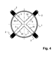
- Buoyancy profile elements 3 which are arranged in a cross are. Each outer end of the profile elements 3 is there connected to a bypass 4 and a gas meter 2.
- buoyancy profile elements 3 necessary pressure difference for the measurement by the different Flow velocities on the top 36 and Profile bottom 37 generated.
- the advantage of these profile elements 3 is that dirt particles that are carried in the gas flow will not get into the feed channels 33 and the gas meter 2 thus better protected against possible contamination are.
- a fifth embodiment according to Figures 5a and 5b are the differential pressure medium Venturi tubes 3 ', which are in the gas tube 1 are arranged.
- the Venturi tubes 3 ' have inlet and outlet openings 32.34 on which the inputs and outputs of bypasses 4 form.
- Each bypass 4 is an outside of the Gas pipe 1 arranged gas meter 2 and a Venturi tube 3 'assigned.
- the gas pipe 1 is thus in several smaller measuring units divided with smaller diameters. That by the individual Gas meter 2 measured values can be combined into a flow profile of the entire cross section of the gas pipe 1 or integrate into a total flow rate.
- the differential pressure means in the embodiment according to the figures 6a and 6b are tube bundles 3 ′′, which are arranged in the gas tube 1 are.
- Each bypass 4 connected to a gas meter 2 is again assigned to a tube bundle 3 ''.
- the tube bundle 3 '' can, as shown here, by pipe sections with a round Cross section be formed. But you can also use pipe sections with a honeycomb or other shape Cross section exist.
- the cross section of the gas pipe 1 divided into sub-areas so that the flow profile or the total flow rate from the individual Partial measurements can be integrated.
- the device according to the invention enables the use of cost-effective, low-wear, static gas meters based on microchips for industrial plants and for large pipe diameters, without reducing the measuring accuracy.
Landscapes
- Physics & Mathematics (AREA)
- Fluid Mechanics (AREA)
- General Physics & Mathematics (AREA)
- Measuring Volume Flow (AREA)
- Sampling And Sample Adjustment (AREA)
Abstract
Description
- Figur 1a
- einen Querschnitt durch ein Gasrohr mit einer erfindungsgemässen Vorrichtung gemäss einer ersten Ausführungsform;
- Figur 1b
- einen Längsschnitt durch die Ausführungsform gemäss Figur 1a;
- Figur 2a
- einen Querschnitt durch eine zweite Ausführungsform;
- Figur 2b
- einen Längsschnitt durch die Ausführungsform gemäss Figur 2a;
- Figur 3a
- einen Querschnitt durch eine dritte Ausführungsform;
- Figur 3b
- einen Längsschnitt durch die Ausführungsform gemäss Figur 3a;
- Figur 4
- einen Querschnitt durch eine vierte Ausführungsform;
- Figur 5a
- einen Querschnitt durch eine fünfte Ausführungsform;
- Figur 5b
- einen Längsschnitt durch die Ausführungsform gemäss Figur 5a;
- Figur 6a
- einen Querschnitt durch eine sechste Ausführungsform und
- Figur 6b
- einen Längsschnitt durch die Ausführungsform gemäss Figur 6a.
- 1
- Gasrohr
- 10
- innere Mantelfläche
- 11
- Mittelachse
- 2
- Gasmeter
- 3
- Profilelemente
- 3'
- Venturirohre
- 3''
- Rohrbündel
- 30
- Seitenfläche
- 31
- Stirnfläche
- 32
- Einlassöffnungen
- 33
- Zuführkanal
- 34
- Auslassöffnungen
- 35
- Wegführkanal
- 36
- Oberseite
- 37
- Unterseite
- 38
- Erster Verbindungskanal
- 39
- Zweiter Verbindungskanal
- 4
- Bypass
Claims (11)
- Vorrichtung zur Messung eines Gasverbrauchs mit mindestens einem Gasmeter (2), wobei das mindestens eine Gasmeter (2) in einem Bypass (4) zu einem Gasrohr (1) angeordnet ist und wobei im Gasrohr (1) mindestens ein lagefixiertes Differenzdruckmittel (3,3',3'') angeordnet ist,
dadurch gekennzeichnet, dass mehrere Differenzdruckmittel (3,3',3'') vorhanden sind, welche über eine Querschnittsfläche des Gasrohres (1) verteilt angeordnet sind,
dass mehrere Gasmeter (2) über Bypässe (4) mit dem Gasrohr (1) verbunden sind und
dass jedem Gasmeter (2) ein Differenzdruckmittel (3,3',3'') zugeordnet ist. - Vorrichtung nach Anspruch 1, dadurch gekennzeichnet, dass die Differenzdruckmittel Profilelemente (3) sind, dass mehrere Einlassöffnungen (32) und Auslassöffnungen (34) vorhanden sind und dass innerhalb jedes Profilelementes (3) ein Zuführ und Wegführkanal (33,35) vorhanden ist, wobei der Zuführkanal (33) die Einlassöffnungen (32) mit dem Bypass (4) verbindet und der Wegführkanal (35) den Bypass (4) mit den Auslassöffnungen (34) verbindet.
- Vorrichtung nach Anspruch 2, dadurch gekennzeichnet, dass die Profilelemente (3) zwei gegenüberliegende Seitenflächen (30) aufweisen, welche an einer inneren Mantelfläche (10) des Gasrohres (1) anliegen.
- Vorrichtung nach Anspruch 2, dadurch gekennzeichnet, dass die Profilelemente (3) einen Längsschnitt in Form eines Staudruckprofils aufweisen, wobei die Einlassöffnungen (32) in Strömungsrichtung des Gases vorne und die Auslassöffnungen (34) mindestens annähernd in einer zur Strömungsrichtung senkrechten Ebene auf einer Oberseite (36) und Unterseite (37) des Profilelementes (3) angeordnet sind.
- Vorrichtung nach Anspruch 2, dadurch gekennzeichnet, dass die Profilelemente (3) einen Längsschnitt in Form eines Auftriebsprofils aufweisen, wobei die Einlassöffnungen (32) auf einer Unterseite (37) des Profilelementes (3) und die Auslassöffnungen (34) auf einer Oberseite (36) des Profilelementes (3) angeordnet sind.
- Vorrichtung nach einem der Ansprüche 4 oder 5, dadurch gekennzeichnet, dass mehrere Profilelemente (3) in Strömungsrichtung senkrecht übereinander im Gasrohr (1) angeordnet sind.
- Vorrichtung nach einem der Ansprüche 4 oder 5, dadurch gekennzeichnet, dass vier Profilelemente (3) ein gemeinsames Kreuz bilden, welches vier Schenkel aufweist, die an ihren freien Enden einer inneren Mantelfläche (10) des Gasrohres (1) anliegen.
- Vorrichtung nach Anspruch 1, dadurch gekennzeichnet, dass die Differenzdruckmittel im Gasrohr (1) angeordnete Venturirohre (3') sind.
- Vorrichtung nach Anspruch 1, dadurch gekennzeichnet, dass die Differenzdruckmittel Rohrbündel (3'') aus Rohrabschnitten sind.
- Vorrichtung nach Anspruch 9, dadurch gekennzeichnet, dass die Rohrabschnitte einen runden oder wabenförmigen Querschnitt aufweisen.
- Vorrichtung nach Anspruch 1, dadurch gekennzeichnet, dass ein Mittel zur gewichteten Mittelung von Messwerten der einzelnen Gasmeter vorhanden ist.
Priority Applications (4)
| Application Number | Priority Date | Filing Date | Title |
|---|---|---|---|
| DE50115059T DE50115059D1 (de) | 2001-09-19 | 2001-09-19 | Vorrichtung zur Messung eines Gasverbrauchs |
| AT01810906T ATE440267T1 (de) | 2001-09-19 | 2001-09-19 | Vorrichtung zur messung eines gasverbrauchs |
| EP01810906A EP1296118B1 (de) | 2001-09-19 | 2001-09-19 | Vorrichtung zur Messung eines Gasverbrauchs |
| PCT/CH2002/000495 WO2003025517A1 (de) | 2001-09-19 | 2002-09-10 | Vorrichtung zur messung eines gasverbrauchs |
Applications Claiming Priority (1)
| Application Number | Priority Date | Filing Date | Title |
|---|---|---|---|
| EP01810906A EP1296118B1 (de) | 2001-09-19 | 2001-09-19 | Vorrichtung zur Messung eines Gasverbrauchs |
Publications (2)
| Publication Number | Publication Date |
|---|---|
| EP1296118A1 true EP1296118A1 (de) | 2003-03-26 |
| EP1296118B1 EP1296118B1 (de) | 2009-08-19 |
Family
ID=8184144
Family Applications (1)
| Application Number | Title | Priority Date | Filing Date |
|---|---|---|---|
| EP01810906A Expired - Lifetime EP1296118B1 (de) | 2001-09-19 | 2001-09-19 | Vorrichtung zur Messung eines Gasverbrauchs |
Country Status (4)
| Country | Link |
|---|---|
| EP (1) | EP1296118B1 (de) |
| AT (1) | ATE440267T1 (de) |
| DE (1) | DE50115059D1 (de) |
| WO (1) | WO2003025517A1 (de) |
Cited By (8)
| Publication number | Priority date | Publication date | Assignee | Title |
|---|---|---|---|---|
| DE102004020284A1 (de) * | 2004-04-26 | 2005-11-17 | Pötter, Friedrich | Staudrucksonde |
| DE102004026766A1 (de) * | 2004-06-02 | 2006-01-05 | Bayerische Motoren Werke Ag | Einrichtung zur Volumenstrommessung |
| WO2006131531A1 (de) * | 2005-06-09 | 2006-12-14 | Siemens Vdo Automotive Ag | Strömungssensor |
| DE102007044079A1 (de) * | 2007-09-14 | 2009-04-16 | Continental Automotive Gmbh | Durchflusssensor |
| EP2068129A1 (de) * | 2003-04-15 | 2009-06-10 | Ems-Patent Ag | Differenzdruckmittel für eine Gaszähleranordnung mit verbesserter Strömungsgeometrie |
| EP2402722A1 (de) * | 2010-06-10 | 2012-01-04 | Woelke Industrieelektronik GmbH | Einrichtung zur Messung der Geschwindigkeit eines Fluids |
| EP2908103A4 (de) * | 2012-10-10 | 2015-10-28 | Panasonic Ip Man Co Ltd | Durchflussmesser |
| CN107817029A (zh) * | 2012-06-15 | 2018-03-20 | 日立汽车系统株式会社 | 热式流量计 |
Families Citing this family (4)
| Publication number | Priority date | Publication date | Assignee | Title |
|---|---|---|---|---|
| KR101847744B1 (ko) * | 2016-12-06 | 2018-05-28 | 두산중공업 주식회사 | 에어로 포일 유량계 |
| KR101902679B1 (ko) * | 2017-01-13 | 2018-09-28 | 두산중공업 주식회사 | 에어로 포일 유량계 |
| KR101902680B1 (ko) * | 2017-01-13 | 2018-09-28 | 두산중공업 주식회사 | 에어로 포일 유량계 |
| KR101902683B1 (ko) * | 2017-01-18 | 2018-11-07 | 두산중공업 주식회사 | 에어로 포일 유량계 |
Citations (4)
| Publication number | Priority date | Publication date | Assignee | Title |
|---|---|---|---|---|
| US1702274A (en) * | 1926-03-30 | 1929-02-19 | Schmidt Ernst | Determining the quantity of flowing liquids or gases |
| US5753825A (en) * | 1996-07-19 | 1998-05-19 | Brandt, Jr.; Robert O. | Velocity averaging pitot |
| EP0947809A2 (de) * | 1998-04-02 | 1999-10-06 | Mostardi-Platt | Verfahren und Vorrichtung zur Messung der Gasgeschwindigkeit oder anderer Strömungscharakteristik |
| US6142148A (en) * | 1997-03-17 | 2000-11-07 | Instrumentarium Corp. | Measuring detector and system for the measurement of gas flow |
Family Cites Families (4)
| Publication number | Priority date | Publication date | Assignee | Title |
|---|---|---|---|---|
| US3803921A (en) * | 1968-07-15 | 1974-04-16 | P Dieterich | Sampling and flow measuring device |
| JPS6333663A (ja) * | 1986-07-28 | 1988-02-13 | Yamatake Honeywell Co Ltd | 流速測定装置 |
| US4959990A (en) * | 1989-04-10 | 1990-10-02 | Morris Robert H | Combined mass flow/pitot tube meter |
| US6655207B1 (en) * | 2000-02-16 | 2003-12-02 | Honeywell International Inc. | Flow rate module and integrated flow restrictor |
-
2001
- 2001-09-19 EP EP01810906A patent/EP1296118B1/de not_active Expired - Lifetime
- 2001-09-19 AT AT01810906T patent/ATE440267T1/de active
- 2001-09-19 DE DE50115059T patent/DE50115059D1/de not_active Expired - Lifetime
-
2002
- 2002-09-10 WO PCT/CH2002/000495 patent/WO2003025517A1/de not_active Ceased
Patent Citations (4)
| Publication number | Priority date | Publication date | Assignee | Title |
|---|---|---|---|---|
| US1702274A (en) * | 1926-03-30 | 1929-02-19 | Schmidt Ernst | Determining the quantity of flowing liquids or gases |
| US5753825A (en) * | 1996-07-19 | 1998-05-19 | Brandt, Jr.; Robert O. | Velocity averaging pitot |
| US6142148A (en) * | 1997-03-17 | 2000-11-07 | Instrumentarium Corp. | Measuring detector and system for the measurement of gas flow |
| EP0947809A2 (de) * | 1998-04-02 | 1999-10-06 | Mostardi-Platt | Verfahren und Vorrichtung zur Messung der Gasgeschwindigkeit oder anderer Strömungscharakteristik |
Cited By (13)
| Publication number | Priority date | Publication date | Assignee | Title |
|---|---|---|---|---|
| EP2068129A1 (de) * | 2003-04-15 | 2009-06-10 | Ems-Patent Ag | Differenzdruckmittel für eine Gaszähleranordnung mit verbesserter Strömungsgeometrie |
| DE102004020284B4 (de) * | 2004-04-26 | 2006-12-28 | Pötter, Friedrich | Staudrucksonde |
| DE102004020284A1 (de) * | 2004-04-26 | 2005-11-17 | Pötter, Friedrich | Staudrucksonde |
| DE102004026766B4 (de) * | 2004-06-02 | 2009-01-02 | Bayerische Motoren Werke Aktiengesellschaft | Einrichtung zur Volumenstrommessung |
| DE102004026766A1 (de) * | 2004-06-02 | 2006-01-05 | Bayerische Motoren Werke Ag | Einrichtung zur Volumenstrommessung |
| WO2006131531A1 (de) * | 2005-06-09 | 2006-12-14 | Siemens Vdo Automotive Ag | Strömungssensor |
| DE102007044079A1 (de) * | 2007-09-14 | 2009-04-16 | Continental Automotive Gmbh | Durchflusssensor |
| DE102007044079B4 (de) * | 2007-09-14 | 2012-02-09 | Continental Automotive Gmbh | Durchflusssensor |
| EP2402722A1 (de) * | 2010-06-10 | 2012-01-04 | Woelke Industrieelektronik GmbH | Einrichtung zur Messung der Geschwindigkeit eines Fluids |
| AU2011202583B2 (en) * | 2010-06-10 | 2015-03-12 | Woelke Industrieelektronik Gmbh | Device for measuring the speed of a fluid |
| CN107817029A (zh) * | 2012-06-15 | 2018-03-20 | 日立汽车系统株式会社 | 热式流量计 |
| EP2908103A4 (de) * | 2012-10-10 | 2015-10-28 | Panasonic Ip Man Co Ltd | Durchflussmesser |
| US9453748B2 (en) | 2012-10-10 | 2016-09-27 | Panasonic Intellectual Property Management Co., Ltd. | Flow meter device |
Also Published As
| Publication number | Publication date |
|---|---|
| EP1296118B1 (de) | 2009-08-19 |
| ATE440267T1 (de) | 2009-09-15 |
| WO2003025517A1 (de) | 2003-03-27 |
| DE50115059D1 (de) | 2009-10-01 |
Similar Documents
| Publication | Publication Date | Title |
|---|---|---|
| DE2938801C2 (de) | Vorrichtung zum Messen der Geschwindigkeit einer Strömung | |
| DE4117422C1 (en) | Monitoring contamination level of filter, partic. for hydraulic fluids - in which signal is produced which correlates with quotient of two pressure differences and evaluating device produces signal to change filter when quotient reaches given value | |
| DE2512644C3 (de) | Vorrichtung zum Bestimmen des Mengenstroms und/oder der Viskosität eines Fluids | |
| EP1296118B1 (de) | Vorrichtung zur Messung eines Gasverbrauchs | |
| DE69331030T2 (de) | Massendurchflussmesser | |
| DE3239126C2 (de) | Strömungsmesser für Fluide | |
| DE3408779A1 (de) | Einstellbarer, laminarer durchflussmesser | |
| EP2072972B1 (de) | Vorrichtung zum Messen der Bewegung eines Fluids in einem Rohr | |
| DE102016118016B4 (de) | Coriolis-Massedurchflussmessgerät mit aktiven und passiven Messrohren | |
| DE2527306A1 (de) | Geraet zur messung des luftmassendurchflusses in einer leitung | |
| DE20208716U1 (de) | Durchfluß-Messvorrichtung | |
| EP3379209A1 (de) | Durchflussmessgerät | |
| DE112018000081B4 (de) | Durchflussmesser | |
| DE10393177T5 (de) | Strömungsrichtvorrichtung | |
| DE2821711A1 (de) | Verfahren und einrichtung zum ueberpruefen eines durchflusszaehlers | |
| EP0007111A2 (de) | Strömungsmesseinrichtung nach dem Prinzip der Kármán'schen Wirbelstrasse | |
| DE2405786C3 (de) | Meßeinrichtungen zur Gasstrommessung in Gasabsaugeleitungen | |
| DE3940474C1 (de) | ||
| DE102007023163B4 (de) | Durchflussmesser | |
| DE102011079993A1 (de) | Strömungsgleichrichter | |
| EP0049756B1 (de) | Vorrichtung zum Messen des Differenzdruckes | |
| DE102011115708A1 (de) | Verfahren zum Ermitteln einer absoluten Strömungsgeschwindigkeit eines Volumen- oder Massenstroms | |
| DE10118810A1 (de) | Wirbelfrequenz-Strömungsmesser | |
| DE4207043A1 (de) | Messwertaufnehmer | |
| DE102012022991A1 (de) | Durchflusssensor |
Legal Events
| Date | Code | Title | Description |
|---|---|---|---|
| PUAI | Public reference made under article 153(3) epc to a published international application that has entered the european phase |
Free format text: ORIGINAL CODE: 0009012 |
|
| AK | Designated contracting states |
Kind code of ref document: A1 Designated state(s): AT BE CH CY DE DK ES FI FR GB GR IE IT LI LU MC NL PT SE TR |
|
| AX | Request for extension of the european patent |
Extension state: AL LT LV MK RO SI |
|
| 17P | Request for examination filed |
Effective date: 20030912 |
|
| AKX | Designation fees paid |
Designated state(s): AT BE CH CY DE DK ES FI FR GB GR IE IT LI LU MC NL PT SE TR |
|
| 17Q | First examination report despatched |
Effective date: 20050607 |
|
| RAP1 | Party data changed (applicant data changed or rights of an application transferred) |
Owner name: EMS-PATENT AG |
|
| RIC1 | Information provided on ipc code assigned before grant |
Ipc: G01F 1/684 20060101ALN20090126BHEP Ipc: G01F 1/42 20060101ALI20090126BHEP Ipc: G01F 1/46 20060101AFI20090126BHEP Ipc: G01F 1/69 20060101ALN20090126BHEP Ipc: G01F 1/44 20060101ALI20090126BHEP Ipc: G01F 5/00 20060101ALN20090126BHEP |
|
| GRAP | Despatch of communication of intention to grant a patent |
Free format text: ORIGINAL CODE: EPIDOSNIGR1 |
|
| GRAS | Grant fee paid |
Free format text: ORIGINAL CODE: EPIDOSNIGR3 |
|
| GRAA | (expected) grant |
Free format text: ORIGINAL CODE: 0009210 |
|
| AK | Designated contracting states |
Kind code of ref document: B1 Designated state(s): AT BE CH CY DE DK ES FI FR GB GR IE IT LI LU MC NL PT SE TR |
|
| REG | Reference to a national code |
Ref country code: GB Ref legal event code: FG4D Free format text: NOT ENGLISH |
|
| REG | Reference to a national code |
Ref country code: CH Ref legal event code: NV Representative=s name: TROESCH SCHEIDEGGER WERNER AG Ref country code: CH Ref legal event code: EP |
|
| REG | Reference to a national code |
Ref country code: IE Ref legal event code: FG4D |
|
| REF | Corresponds to: |
Ref document number: 50115059 Country of ref document: DE Date of ref document: 20091001 Kind code of ref document: P |
|
| PGFP | Annual fee paid to national office [announced via postgrant information from national office to epo] |
Ref country code: IE Payment date: 20090921 Year of fee payment: 9 |
|
| PG25 | Lapsed in a contracting state [announced via postgrant information from national office to epo] |
Ref country code: FI Free format text: LAPSE BECAUSE OF FAILURE TO SUBMIT A TRANSLATION OF THE DESCRIPTION OR TO PAY THE FEE WITHIN THE PRESCRIBED TIME-LIMIT Effective date: 20090819 Ref country code: ES Free format text: LAPSE BECAUSE OF FAILURE TO SUBMIT A TRANSLATION OF THE DESCRIPTION OR TO PAY THE FEE WITHIN THE PRESCRIBED TIME-LIMIT Effective date: 20091130 Ref country code: SE Free format text: LAPSE BECAUSE OF FAILURE TO SUBMIT A TRANSLATION OF THE DESCRIPTION OR TO PAY THE FEE WITHIN THE PRESCRIBED TIME-LIMIT Effective date: 20090819 |
|
| RAP2 | Party data changed (patent owner data changed or rights of a patent transferred) |
Owner name: HYDROMETER GMBH |
|
| REG | Reference to a national code |
Ref country code: CH Ref legal event code: PUE Owner name: YDROMETER GMBH Free format text: EMS-PATENT AG#REICHENAUERSTRASSE#7013 DOMAT/EMS (CH) -TRANSFER TO- HYDROMETER GMBH#INDUSTRIESTRASSE 13#91522 ANSBACH (DE) |
|
| REG | Reference to a national code |
Ref country code: IE Ref legal event code: FD4D |
|
| BERE | Be: lapsed |
Owner name: EMS-PATENT A.G. Effective date: 20090930 |
|
| PG25 | Lapsed in a contracting state [announced via postgrant information from national office to epo] |
Ref country code: PT Free format text: LAPSE BECAUSE OF FAILURE TO SUBMIT A TRANSLATION OF THE DESCRIPTION OR TO PAY THE FEE WITHIN THE PRESCRIBED TIME-LIMIT Effective date: 20091221 Ref country code: CY Free format text: LAPSE BECAUSE OF FAILURE TO SUBMIT A TRANSLATION OF THE DESCRIPTION OR TO PAY THE FEE WITHIN THE PRESCRIBED TIME-LIMIT Effective date: 20090819 |
|
| NLS | Nl: assignments of ep-patents |
Owner name: HYDROMETER GMBH Effective date: 20100121 |
|
| PG25 | Lapsed in a contracting state [announced via postgrant information from national office to epo] |
Ref country code: MC Free format text: LAPSE BECAUSE OF NON-PAYMENT OF DUE FEES Effective date: 20090930 Ref country code: IE Free format text: LAPSE BECAUSE OF FAILURE TO SUBMIT A TRANSLATION OF THE DESCRIPTION OR TO PAY THE FEE WITHIN THE PRESCRIBED TIME-LIMIT Effective date: 20090819 Ref country code: DK Free format text: LAPSE BECAUSE OF FAILURE TO SUBMIT A TRANSLATION OF THE DESCRIPTION OR TO PAY THE FEE WITHIN THE PRESCRIBED TIME-LIMIT Effective date: 20090819 |
|
| REG | Reference to a national code |
Ref country code: FR Ref legal event code: TP |
|
| PLBE | No opposition filed within time limit |
Free format text: ORIGINAL CODE: 0009261 |
|
| STAA | Information on the status of an ep patent application or granted ep patent |
Free format text: STATUS: NO OPPOSITION FILED WITHIN TIME LIMIT |
|
| 26N | No opposition filed |
Effective date: 20100520 |
|
| PG25 | Lapsed in a contracting state [announced via postgrant information from national office to epo] |
Ref country code: BE Free format text: LAPSE BECAUSE OF NON-PAYMENT OF DUE FEES Effective date: 20090930 |
|
| REG | Reference to a national code |
Ref country code: GB Ref legal event code: 732E Free format text: REGISTERED BETWEEN 20100819 AND 20100825 |
|
| PG25 | Lapsed in a contracting state [announced via postgrant information from national office to epo] |
Ref country code: GR Free format text: LAPSE BECAUSE OF FAILURE TO SUBMIT A TRANSLATION OF THE DESCRIPTION OR TO PAY THE FEE WITHIN THE PRESCRIBED TIME-LIMIT Effective date: 20091120 |
|
| PG25 | Lapsed in a contracting state [announced via postgrant information from national office to epo] |
Ref country code: LU Free format text: LAPSE BECAUSE OF NON-PAYMENT OF DUE FEES Effective date: 20090919 |
|
| PGFP | Annual fee paid to national office [announced via postgrant information from national office to epo] |
Ref country code: CH Payment date: 20110923 Year of fee payment: 11 |
|
| PGFP | Annual fee paid to national office [announced via postgrant information from national office to epo] |
Ref country code: GB Payment date: 20120920 Year of fee payment: 12 |
|
| PGFP | Annual fee paid to national office [announced via postgrant information from national office to epo] |
Ref country code: TR Payment date: 20120828 Year of fee payment: 12 |
|
| PGFP | Annual fee paid to national office [announced via postgrant information from national office to epo] |
Ref country code: FR Payment date: 20121010 Year of fee payment: 12 Ref country code: NL Payment date: 20120920 Year of fee payment: 12 |
|
| PGFP | Annual fee paid to national office [announced via postgrant information from national office to epo] |
Ref country code: AT Payment date: 20120912 Year of fee payment: 12 |
|
| REG | Reference to a national code |
Ref country code: NL Ref legal event code: V1 Effective date: 20140401 |
|
| REG | Reference to a national code |
Ref country code: CH Ref legal event code: PL |
|
| REG | Reference to a national code |
Ref country code: AT Ref legal event code: MM01 Ref document number: 440267 Country of ref document: AT Kind code of ref document: T Effective date: 20130919 |
|
| GBPC | Gb: european patent ceased through non-payment of renewal fee |
Effective date: 20130919 |
|
| REG | Reference to a national code |
Ref country code: FR Ref legal event code: ST Effective date: 20140530 |
|
| PG25 | Lapsed in a contracting state [announced via postgrant information from national office to epo] |
Ref country code: GB Free format text: LAPSE BECAUSE OF NON-PAYMENT OF DUE FEES Effective date: 20130919 Ref country code: CH Free format text: LAPSE BECAUSE OF NON-PAYMENT OF DUE FEES Effective date: 20130930 Ref country code: LI Free format text: LAPSE BECAUSE OF NON-PAYMENT OF DUE FEES Effective date: 20130930 |
|
| PG25 | Lapsed in a contracting state [announced via postgrant information from national office to epo] |
Ref country code: FR Free format text: LAPSE BECAUSE OF NON-PAYMENT OF DUE FEES Effective date: 20130930 Ref country code: AT Free format text: LAPSE BECAUSE OF NON-PAYMENT OF DUE FEES Effective date: 20130919 Ref country code: NL Free format text: LAPSE BECAUSE OF NON-PAYMENT OF DUE FEES Effective date: 20140401 |
|
| REG | Reference to a national code |
Ref country code: DE Ref legal event code: R082 Ref document number: 50115059 Country of ref document: DE Representative=s name: PFENNING MEINIG & PARTNER GBR, DE |
|
| REG | Reference to a national code |
Ref country code: DE Ref legal event code: R082 Ref document number: 50115059 Country of ref document: DE Representative=s name: PFENNING MEINIG & PARTNER GBR, DE Effective date: 20150506 Ref country code: DE Ref legal event code: R081 Ref document number: 50115059 Country of ref document: DE Owner name: DIEHL METERING GMBH, DE Free format text: FORMER OWNER: HYDROMETER GMBH, 91522 ANSBACH, DE Effective date: 20150506 Ref country code: DE Ref legal event code: R082 Ref document number: 50115059 Country of ref document: DE Representative=s name: PFENNING, MEINIG & PARTNER MBB PATENTANWAELTE, DE Effective date: 20150506 |
|
| PG25 | Lapsed in a contracting state [announced via postgrant information from national office to epo] |
Ref country code: TR Free format text: LAPSE BECAUSE OF NON-PAYMENT OF DUE FEES Effective date: 20130919 |
|
| PGFP | Annual fee paid to national office [announced via postgrant information from national office to epo] |
Ref country code: DE Payment date: 20161123 Year of fee payment: 16 |
|
| PGFP | Annual fee paid to national office [announced via postgrant information from national office to epo] |
Ref country code: IT Payment date: 20170926 Year of fee payment: 17 |
|
| REG | Reference to a national code |
Ref country code: DE Ref legal event code: R119 Ref document number: 50115059 Country of ref document: DE |
|
| PG25 | Lapsed in a contracting state [announced via postgrant information from national office to epo] |
Ref country code: DE Free format text: LAPSE BECAUSE OF NON-PAYMENT OF DUE FEES Effective date: 20180404 |
|
| PG25 | Lapsed in a contracting state [announced via postgrant information from national office to epo] |
Ref country code: IT Free format text: LAPSE BECAUSE OF NON-PAYMENT OF DUE FEES Effective date: 20180919 |