EP1295995A1 - Construction machinery - Google Patents
Construction machinery Download PDFInfo
- Publication number
- EP1295995A1 EP1295995A1 EP01915770A EP01915770A EP1295995A1 EP 1295995 A1 EP1295995 A1 EP 1295995A1 EP 01915770 A EP01915770 A EP 01915770A EP 01915770 A EP01915770 A EP 01915770A EP 1295995 A1 EP1295995 A1 EP 1295995A1
- Authority
- EP
- European Patent Office
- Prior art keywords
- cooling
- cooling unit
- unit group
- disposed
- construction machine
- Prior art date
- Legal status (The legal status is an assumption and is not a legal conclusion. Google has not performed a legal analysis and makes no representation as to the accuracy of the status listed.)
- Withdrawn
Links
- 238000010276 construction Methods 0.000 title claims abstract description 53
- 238000001816 cooling Methods 0.000 claims abstract description 269
- 238000004140 cleaning Methods 0.000 claims abstract description 18
- 238000005192 partition Methods 0.000 claims description 42
- 238000011144 upstream manufacturing Methods 0.000 claims description 7
- 238000007599 discharging Methods 0.000 claims description 3
- 230000002708 enhancing effect Effects 0.000 abstract description 3
- 230000004048 modification Effects 0.000 description 10
- 238000012986 modification Methods 0.000 description 10
- 239000000428 dust Substances 0.000 description 7
- 230000000694 effects Effects 0.000 description 7
- 230000001629 suppression Effects 0.000 description 3
- 238000009423 ventilation Methods 0.000 description 3
- 239000002826 coolant Substances 0.000 description 2
- 229910000838 Al alloy Inorganic materials 0.000 description 1
- 238000002485 combustion reaction Methods 0.000 description 1
- 230000006835 compression Effects 0.000 description 1
- 238000007906 compression Methods 0.000 description 1
- 239000000498 cooling water Substances 0.000 description 1
- 239000013013 elastic material Substances 0.000 description 1
- 230000003203 everyday effect Effects 0.000 description 1
- 239000002828 fuel tank Substances 0.000 description 1
- 230000020169 heat generation Effects 0.000 description 1
- 239000000203 mixture Substances 0.000 description 1
- 238000000746 purification Methods 0.000 description 1
- 230000001743 silencing effect Effects 0.000 description 1
- 230000002195 synergetic effect Effects 0.000 description 1
- XLYOFNOQVPJJNP-UHFFFAOYSA-N water Substances O XLYOFNOQVPJJNP-UHFFFAOYSA-N 0.000 description 1
Images


Classifications
-
- E—FIXED CONSTRUCTIONS
- E02—HYDRAULIC ENGINEERING; FOUNDATIONS; SOIL SHIFTING
- E02F—DREDGING; SOIL-SHIFTING
- E02F9/00—Component parts of dredgers or soil-shifting machines, not restricted to one of the kinds covered by groups E02F3/00 - E02F7/00
- E02F9/08—Superstructures; Supports for superstructures
- E02F9/0858—Arrangement of component parts installed on superstructures not otherwise provided for, e.g. electric components, fenders, air-conditioning units
- E02F9/0866—Engine compartment, e.g. heat exchangers, exhaust filters, cooling devices, silencers, mufflers, position of hydraulic pumps in the engine compartment
-
- E—FIXED CONSTRUCTIONS
- E02—HYDRAULIC ENGINEERING; FOUNDATIONS; SOIL SHIFTING
- E02F—DREDGING; SOIL-SHIFTING
- E02F9/00—Component parts of dredgers or soil-shifting machines, not restricted to one of the kinds covered by groups E02F3/00 - E02F7/00
-
- F—MECHANICAL ENGINEERING; LIGHTING; HEATING; WEAPONS; BLASTING
- F01—MACHINES OR ENGINES IN GENERAL; ENGINE PLANTS IN GENERAL; STEAM ENGINES
- F01P—COOLING OF MACHINES OR ENGINES IN GENERAL; COOLING OF INTERNAL-COMBUSTION ENGINES
- F01P3/00—Liquid cooling
- F01P3/18—Arrangements or mounting of liquid-to-air heat-exchangers
-
- B—PERFORMING OPERATIONS; TRANSPORTING
- B60—VEHICLES IN GENERAL
- B60K—ARRANGEMENT OR MOUNTING OF PROPULSION UNITS OR OF TRANSMISSIONS IN VEHICLES; ARRANGEMENT OR MOUNTING OF PLURAL DIVERSE PRIME-MOVERS IN VEHICLES; AUXILIARY DRIVES FOR VEHICLES; INSTRUMENTATION OR DASHBOARDS FOR VEHICLES; ARRANGEMENTS IN CONNECTION WITH COOLING, AIR INTAKE, GAS EXHAUST OR FUEL SUPPLY OF PROPULSION UNITS IN VEHICLES
- B60K11/00—Arrangement in connection with cooling of propulsion units
- B60K11/02—Arrangement in connection with cooling of propulsion units with liquid cooling
- B60K11/04—Arrangement or mounting of radiators, radiator shutters, or radiator blinds
-
- B—PERFORMING OPERATIONS; TRANSPORTING
- B60—VEHICLES IN GENERAL
- B60K—ARRANGEMENT OR MOUNTING OF PROPULSION UNITS OR OF TRANSMISSIONS IN VEHICLES; ARRANGEMENT OR MOUNTING OF PLURAL DIVERSE PRIME-MOVERS IN VEHICLES; AUXILIARY DRIVES FOR VEHICLES; INSTRUMENTATION OR DASHBOARDS FOR VEHICLES; ARRANGEMENTS IN CONNECTION WITH COOLING, AIR INTAKE, GAS EXHAUST OR FUEL SUPPLY OF PROPULSION UNITS IN VEHICLES
- B60K11/00—Arrangement in connection with cooling of propulsion units
- B60K11/08—Air inlets for cooling; Shutters or blinds therefor
-
- F—MECHANICAL ENGINEERING; LIGHTING; HEATING; WEAPONS; BLASTING
- F01—MACHINES OR ENGINES IN GENERAL; ENGINE PLANTS IN GENERAL; STEAM ENGINES
- F01P—COOLING OF MACHINES OR ENGINES IN GENERAL; COOLING OF INTERNAL-COMBUSTION ENGINES
- F01P3/00—Liquid cooling
- F01P3/18—Arrangements or mounting of liquid-to-air heat-exchangers
- F01P2003/182—Arrangements or mounting of liquid-to-air heat-exchangers with multiple heat-exchangers
-
- F—MECHANICAL ENGINEERING; LIGHTING; HEATING; WEAPONS; BLASTING
- F01—MACHINES OR ENGINES IN GENERAL; ENGINE PLANTS IN GENERAL; STEAM ENGINES
- F01P—COOLING OF MACHINES OR ENGINES IN GENERAL; COOLING OF INTERNAL-COMBUSTION ENGINES
- F01P3/00—Liquid cooling
- F01P3/18—Arrangements or mounting of liquid-to-air heat-exchangers
- F01P2003/185—Arrangements or mounting of liquid-to-air heat-exchangers arranged in parallel
-
- F—MECHANICAL ENGINEERING; LIGHTING; HEATING; WEAPONS; BLASTING
- F01—MACHINES OR ENGINES IN GENERAL; ENGINE PLANTS IN GENERAL; STEAM ENGINES
- F01P—COOLING OF MACHINES OR ENGINES IN GENERAL; COOLING OF INTERNAL-COMBUSTION ENGINES
- F01P3/00—Liquid cooling
- F01P3/18—Arrangements or mounting of liquid-to-air heat-exchangers
- F01P2003/187—Arrangements or mounting of liquid-to-air heat-exchangers arranged in series
-
- F—MECHANICAL ENGINEERING; LIGHTING; HEATING; WEAPONS; BLASTING
- F01—MACHINES OR ENGINES IN GENERAL; ENGINE PLANTS IN GENERAL; STEAM ENGINES
- F01P—COOLING OF MACHINES OR ENGINES IN GENERAL; COOLING OF INTERNAL-COMBUSTION ENGINES
- F01P11/00—Component parts, details, or accessories not provided for in, or of interest apart from, groups F01P1/00 - F01P9/00
- F01P11/06—Cleaning; Combating corrosion
- F01P2011/063—Cleaning
-
- F—MECHANICAL ENGINEERING; LIGHTING; HEATING; WEAPONS; BLASTING
- F01—MACHINES OR ENGINES IN GENERAL; ENGINE PLANTS IN GENERAL; STEAM ENGINES
- F01P—COOLING OF MACHINES OR ENGINES IN GENERAL; COOLING OF INTERNAL-COMBUSTION ENGINES
- F01P2060/00—Cooling circuits using auxiliaries
- F01P2060/02—Intercooler
-
- F—MECHANICAL ENGINEERING; LIGHTING; HEATING; WEAPONS; BLASTING
- F01—MACHINES OR ENGINES IN GENERAL; ENGINE PLANTS IN GENERAL; STEAM ENGINES
- F01P—COOLING OF MACHINES OR ENGINES IN GENERAL; COOLING OF INTERNAL-COMBUSTION ENGINES
- F01P2060/00—Cooling circuits using auxiliaries
- F01P2060/04—Lubricant cooler
-
- F—MECHANICAL ENGINEERING; LIGHTING; HEATING; WEAPONS; BLASTING
- F01—MACHINES OR ENGINES IN GENERAL; ENGINE PLANTS IN GENERAL; STEAM ENGINES
- F01P—COOLING OF MACHINES OR ENGINES IN GENERAL; COOLING OF INTERNAL-COMBUSTION ENGINES
- F01P2060/00—Cooling circuits using auxiliaries
- F01P2060/14—Condenser
-
- F—MECHANICAL ENGINEERING; LIGHTING; HEATING; WEAPONS; BLASTING
- F01—MACHINES OR ENGINES IN GENERAL; ENGINE PLANTS IN GENERAL; STEAM ENGINES
- F01P—COOLING OF MACHINES OR ENGINES IN GENERAL; COOLING OF INTERNAL-COMBUSTION ENGINES
- F01P2070/00—Details
Definitions
- the present invention relates to a construction machine equipped with an engine and a plurality of cooling units, in which some of the cooling units are disposed in parallel and cooled with a single cooling fan in order to enhance the cooling efficiency, reduce the leakage of operation noise, and facilitate the cooling of the cooling units.
- Construction machines include, for example, a hydraulic shovel that performs a digging operation for a dam, a tunnel, a road, water supply and drainage, etc., or a dismantling operation for constructions, etc.
- the hydraulic shovel is constructed of a lower travel body, an upper swivel body supported on the lower travel body so that it can swivel, and a working unit provided on the front portion of the upper swivel body.
- the upper swivel body is usually provided with a driver's cab.
- a driver's cab there are cases where small hydraulic shovels have not a driver's cab but a driver's seat.
- the frame of the swivel body is provided with an engine, a hydraulic pump, cooling units, batteries, control valves, a fuel tank, a working-oil tank, etc.
- the construction machine performs various operations such as traveling by the lower travel body, swiveling by the upper swivel body, digging by the working unit, etc. These operations are performed by a hydraulic actuator, constructed of a hydraulic motor, a hydraulic cylinder, etc. As shown in Fig. 11, pressure oil is supplied to the hydraulic actuator by the hydraulic pump 05 that is driven by the engine 03.
- units such as the engine 03, radiator 06, hydraulic pump 05, and direction-switching valves for switching the direction of the pressure oil supplied from the hydraulic pump 05, are disposed within the upper swivel body.
- the upper swivel body is provided with an engine room 02 having a cover 01. Within the engine room 02, the engine 03 is provided, and the radiator 06 for cooling the engine 03, an oil cooler 010 for cooling working oil, an intercooler 08 for cooling air which is supplied to the combustion chamber of the engine 03, and a condenser 012, are disposed.
- the intercooler 08, oil cooler 010, radiator 06, and condenser 012 constitute a first cooling unit group R which is used to cool working oil and cooling water.
- a cooling fan 014 is disposed.
- the cooling fan 014 is driven by the engine 03.
- the cover 01 that constitutes part of the engine room 02 is provided with outside-air introducing ports 01a for introducing the outside air, and exhaust ports 01b for discharging the introduced air.
- the introduced air cools the first cooling unit group Rand then the engine 03, the hydraulic pump 05, and the direction switching valves. Thereafter, the air that has reached high temperature is discharged from the exhaust ports 01b to the outside.
- cooling air is introduced through the outside-air introducing ports 01a.
- a flow of air occurs as indicated by arrows, cools the engine 02, the hydraulic pump 05, the direction switching valves, etc., and is discharged from the exhaust ports 01b.
- the cooling air flows in the order of condenser 012, intercooler 08, oil cooler 010, and radiator 06 from the upstream side.
- the intercooler 08 is used for cooling air compressed by a supercharger 016 that increases the pressure of the fuel-air mixture in the engine 03. Because of this, a filter unit 017 is provided on the exterior of the engine room 02 to prevent the entry of dust and dirt.
- the supercharger 016 is used to compress introduced air by rotating the turbine with the energy of the exhaust gas of the engine 03. Since the temperature of the introduced air rises due to adiabatic compression, it is necessary to cool the introduced air before it is supplied to the engine 03, for the output of the engine 03 and purification of the exhaust gas.
- the introduced air is cooled by the intercooler 08, and is generally cooled to about 40 to 70°C at the normal temperature.
- the intercooler 08 Since the coolant of the intercooler 08 has to be cooled to a temperature lower than those of other heat exchangers, and the quantity of the radiant heat of the oil cooler 010 and the radiator 06 is relatively large, the intercooler 08 is generally disposed on the most upstream side of a flow of air, or on the upstream side from the radiator 06.
- conduits 018, 019 for circulating compressed air are connected between the supercharger 016 and the intercooler 08 and between the intercooler 08 and the engine 03.
- the aforementioned heat exchange is performed in the order of condenser 12, intercooler 08, oil cooler 010, and radiator 06, and in order to enhance the cooling efficiency, the condenser 12, the intercooler 08, the oil cooler 010, and the radiator 06 are disposed in close proximity to one another.
- dust and dirt tend to adhere to the condenser 012, the intercooler 08, the oil cooler 010, and the radiator 06. If dust and dirt adhere to the condenser 012, the intercooler 08, the oil cooler 010, and the radiator 06, the aforementioned various operations cannot be continued unless they are frequently cleaned.
- the intercooler 08, the oil cooler 010, and the radiator 06 are disposed in the recited order, there are cases where, in a narrow space within the engine room 02 of the hydraulic shovel, particularly a narrow space within the engine room of a small hydraulic shovel, rotation of the oil cooler 010 becomes difficult.
- the intercooler 08 is disposed so as to face the oil cooler 010 or radiator 06, the intercooler 08 becomes a hindrance and therefore the oil cooler 010 cannot be cleaned.
- the radiator 06 or oil cooler 010 is made of a lightweight aluminum alloy so that it can be easily lifted upward.
- the radiator 06 or oil cooler 010 is first lifted upward to form an open space behind the intercooler 08.
- the intercooler 08 is cleaned, for example, with an air jet nozzle.
- the removed radiator 06 or oil cooler 010 is also cleaned, and is returned to the original position.
- the first cooling unit group R, the engine 03, and the hydraulic pump 05 are disposed in a cooling-air passage which is widely communicated through a core having the area of the wide cooling-air passage of the cooling units within the engine room 02. Therefore, there is a fear that noise generated by the engine 03 and the cooling fan 014 will be transmitted from the wide area to the outside.
- the cooling fan 014 will be clogged by dust and dirt. As a result, the circulation of the cooling air for the first cooling unit group R is reduced and the cooling efficiency becomes low. Because of this, the performance of the construction machine cannot be sufficiently utilized.
- removing and installing the radiator 06 or oil cooler 010 require labor and time, resulting in a reduction in the operation efficiency. Furthermore, as described above, there is a fear that noise will be transmitted to the outside of the construction machine.
- the present invention has been made in view of the problems mentioned above. Accordingly, it is the primary object of the present invention to provide a construction machine that is capable of easily cleaning the cooling units, enhancing the cooling efficiency, and reducing noise.
- the construction machine is equipped with a first cooling unit group consisting of a plurality of cooling units, and a second cooling unit group where some cooling units in the first cooling unit group are disposed in parallel.
- the remaining cooling unit of the first cooling unit group is disposed with a gap between itself and the second cooling unit group, or is disposed in parallel with the second cooling unit group.
- the construction machine is further equipped with a cooling fan disposed so that it faces the cooling units disposed as described above.
- a first construction machine comprising: a nearly sealed engine room section where an engine is disposed; a first cooling unit group comprising a plurality of cooling units; and a single cooling fan for cooling a second cooling unit group where some cooling units of the first cooling unit group are disposed in parallel; wherein the second cooling unit group and the cooling fan are disposed so that they face each other.
- a construction machine comprising: a first cooling unit group comprising a plurality of cooling units; a cooling fan for cooling a second cooling unit group where some cooling units of the first cooling unit group are disposed in parallel; an engine; a partition member provided between the cooling fan and the engine; a chamber, partitioned and formed by the partition member, where the first cooling unit group and the cooling fan are disposed; and a nearly sealed engine room section, partitioned by the partition member, where the engine is disposed; wherein the cooling fan comprises a single cooling fan.
- the second cooling unit group and the remaining cooling unit of the first cooling unit group are disposed so that they face each other .
- the whole of the cooling units can be made compact.
- the cooling efficiency can be enhanced with the single cooling fan, and the operation cost can be reduced.
- a gap is provided between the second cooling unit group and the remaining cooling unit so that cleaning can be performed.
- a gap-closing cover is provided to nearly close at least the circumference of the gap and is rotatable or detachable. This can prevent a reduction in the cooling efficiency due to the leakage of the cooling air from the gap. In the case where the rotatable or detachable gap-closing cover is used, the cooling efficiency can be enhanced. In addition, in cleaning the cooling units, the rotatable or detachable gap-closing cover is rotated or removed, and dust and dirt on the cooling unit can be easily cleaned, for example, by inserting an air jet nozzle into the gap.
- a degree of freedom in designing the gap D and the height H can be increased and the gap D and the height H can be suitably disposed according to design specification.
- the gap D is set to about 30 to 300 mm, preferably about 40 to 100 mm. Because of this, there is an effect that the cooling units can be easily set according to design specification by the gap D.
- the cooling unit of the second cooling unit group on the upstream side of the remaining cooling unit comprises an intercooler. This makes it possible to easily perform cleaning of the cooling units including the intercooler.
- the nearly sealed engine room section is constructed so that cooling air introduced by the cooling fan is drawn in, or is constructed so that it is ventilated by discharging the cooling air within the nearly sealed engine room section, which has risen in temperature, from blowoff bores of the partition member with the cooling air introduced by the cooling fan.
- the cooling fan comprises an axial flow fan, a bent axis flow fan, or a centrifugal fan. Therefore, by suitably using an axial flow fan, a bent axis flow fan, or a centrifugal fan, the cooling efficiency can be enhanced and the cooling fan can be made compact.
- the nearly sealed engine room section is provided with an ejector. With the ejector, cooling within the nearly sealed engine room section can be efficiently performed.
- the nearly sealed engine room section is provided with an ejector and a ventilating fan.
- the synergetic effect of the ejector and the ventilating fan can enhance the cooling effect within the nearly sealed engine room section.
- the construction machine of the present invention further comprises cylindrical guide members which have a communicating bore corresponding and communicating with a communicating bore or blowoff bore provided in the partition member.
- the cylindrical guide members make it possible to enhance the cooling effect within the nearly sealed engine room section.
- Fig. 1 shows a hydraulic shovel to which a construction machine of a first embodiment of the present invention is applied.
- the hydraulic shovel P of the first embodiment of the present invention is constructed of an upper swivel body 2, a lower travel body 4, and a working unit 6.
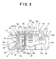
- the front end portion of the upper swivel body 2 is provided with a driver's cab 8, and the rear end portion is provided with a counterweight 10. Furthermore, a suction-type engine room 12, as shown in Figs. 2 and 3, is provided on the frame of the upper swivel body 2 and disposed in front of the counterweight 10 of the hydraulic shovel P.
- a first cooling unit group R which consists of an intercooler 14, an oil cooler 16, and a radiator 18.
- the oil cooler 16 and the intercooler 14 in the first cooling unit group R are disposed in parallel in a vertical direction and constitute a second cooling unit group R1.
- the radiator 18, which is the remaining cooling unit RN of the first cooling unit group R, is disposed on the downstream side of the second cooling unit group R1.
- the oil cooler 16 is disposed in close proximity to the upper portion of the radiator 18.
- the intercooler 14 is disposed in closeproximity to the lower portion of the oil cooler 16 with the gap D between the intercooler 14 and the radiator 18, determined by design specification.
- a single cooling fan 20 is provided on the downstream side of the first cooling unit group R disposed within the engine room 12 and is used to cool the first cooling unit group R.
- an engine 22 and a hydraulic pump 24 connected to the engine 22 are provided behind the cooling fan 20. Between the engine 22 and the hydraulic pump 24, there is provided a partition plate DW.
- a partition member 26 is provided between the cooling fan 20 and the engine 22.
- the first cooling unit group R and the cooling fan 20 are disposed.
- the engine 22 and the hydraulic pump 24 are disposed.
- the aforementioned second cooling unit group R1 (the intercooler 14 and the oil cooler 17 in the first embodiment) and the remaining cooling unit RN (the radiator 18 in the first embodiment) of the first cooling unit group R are disposed so as to face each other, and are cooled by the single cooling fan 20.
- a plurality of guide members 26R are provided on the downstream side of the partition member 26 (back surface of the partition member 26).
- Each guide member 26R is formed in cylindrical form by guide pieces 26R1, 26R2 provided around a communicating bore 26a formed in the partition member 26.
- the guide member 26R is square in cross section.
- This guide member 26R has at least the size of the communicating bore 26a formed in the partition member 26. It is preferable that the guide member 26R be a communicating bore larger than the communicating bore 26a.
- conduits 34, 36 for circulating compressed air are connected between the supercharger 32 and the intercooler 14 and between the intercooler 14 and the engine 22, respectively.
- the conduits 34, 36 penetrate the partition member 26, the radially outer portion of the radiator 18, and a partition plate 18a.
- the partition plate 18a is provided between an upper partition wall (engine hood) Wa, a front partition wall Wb, a rear partition wall Wc, and a bottom partition wall Wd which constitute a cover 1.
- the cover 1 constitutes the engine room 12.
- the cover 1 further has side partition walls Ws, Ws between the front partition wall Wb and the rear partition wall Wc.
- Amuffler 38 connected to an exhaust port is provided on the rear upper portion of the engine 22 so that exhaust gas is discharged from the engine 22 through an exhaust pipe 40.
- part of the exhaust gas is supplied to the supercharger 32 through an exhaust pipe 32a to drive the supercharger 32.
- the oil cooler 16 for example, is constructed so that it is rotatable on a rotation axis AX through a hinge mechanism 44 provided between the oil cooler 16 and the radiator 18 (or the upper swivel body 2).
- the conduits 17a, 17b of the oil cooler 16 are connected through rotatable tube fittings 21, 21.
- the tube fittings 21 are rotatable coaxially with the rotation axis AX and provided on a working-oil supply side and a working-oil exhaust side. Therefore, even if the oil cooler 16 rotates, the conduits 17a, 17b are prevented from being twisted or damaged.
- the suction-type nearly sealed engine room section 30 of the first embodiment is constructed as described above. Therefore, if the engine 22 and the cooling fan 20 are operated, cooling air is introduced through the outside-air introducing port 1a of the cover 1 and then cools the first cooling unit group R. Thereafter, the cooling air passes through the communicating bores 26a of the partition member 26 and through the guide members 26R, is introduced into the nearly sealed engine room section 30, and cools the engine 22, the muffler 38, etc. After that, the cooling air is discharged from an exhaust port 1b provided on the cover 1.
- the radiator 18, the oil cooler 16, and the intercooler 14 are efficiently cooled with the single cooling fan 20.
- cleaning of the first cooling unit group R must be frequently performed. For example, particularly, in a construction site where dismantling of a structure is performed, cleaning of the first cooling unit group R must be performed every day, or a plurality of times a day as occasion demands.
- the construction of the first cooling unit group R of the first embodiment is useful.
- the oil cooler 16 of the second cooling unit group R1 oil cooler 16 and intercooler 14 of the first cooling unit group R (radiator 18, oil cooler 16, and intercooler 14) is rotatable as shown in Fig. 4(B) through the hinge mechanism 44 with respect to the remaining cooling unit RN (radiator 18) of the first cooling unit group R so that an open space can be formed above the top surface of the intercooler 14. Therefore, the intercooler 14 and the radiator 18 can be easily cleaned by inserting an air jet nozzle into the gap between the radiator 18 and the intercooler 14 and then jetting air. Similarly, the oil cooler 16 and the radiator 18 in the open states can be easily cleaned with a jet of air.
- the oil cooler 16 is returned to its original position, as shown in Fig. 4(A).
- the oil cooler 16 can be easily and detachably fastened by engaging thumbscrews 48a with the engaging bolt 48 of a hinge mechanism 46 that is used as a stopper member provided between the oil cooler 16 and the intercooler 14.
- the gap D between the intercooler 14 and at least one cooling unit (radiator 18 in the first embodiment) of the first cooling unit group R is suitably determined by design specification.
- the gap D is determined so that a ratio of D/H becomes about 0.05 to 0.3.
- the letter H in the ratio of D/H represents the height of the intercooler 14 that faces at least one cooling unit (radiator 18 in the first embodiment) of the first cooling unit group R.
- the gap D is usually set to about 30 to 200 mm. In the case of large machine types and special machine types, the gape D is set to about 30 to 300 mm. It is preferable that the gap D be set to about 40 to 100 mm.
- the intercooler 14 is disposed so that it faces one cooling unit of the first cooling unit group R.
- the cooling unit that faces one cooling unit of the first cooling unit group R is not limited to the intercooler 14. In the case where two other cooling units in the first cooling unit group R are disposed so that they face each other, the same effect as the first embodiment can be obtained, if the aforementioned gap D is provided between the two cooling units.
- the remaining cooling unit RN (intercooler 14) of the first cooling unit group R is disposed as shown in Fig. 5. Furthermore, a condenser 19 for an air conditioner is disposed with the gap D between itself and the oil cooler 16.
- cooling can be performed with the single cooling fan 20. Therefore, the operation costs can be reduced.
- cleaning can be easily performed by inserting the aforementioned air jet nozzle into the gap D between the intercooler 14 and the radiator 18 and the gap D between the oil cooler 16 and the condenser 19 and then jetting air. Therefore, the operation efficiency can be enhanced.
- the remaining cooling unit RN (intercooler 14) of the first cooling unit group R is disposed as shown in Fig. 6(A).
- cooling can be performed with the single cooling fan 20. Therefore, the operation costs can be reduced.
- cleaning can be easily performed by inserting the aforementioned air jet nozzle into the gap D between the second cooling unit group R1 (oil cooler 16 and radiator 18) and the remaining cooling unit RN (intercooler 14) and then jetting air. Therefore, the operation efficiency can be enhanced.
- gap-closing covers CV are provided to nearly close at least the circumference of the gap D shown in Fig. 6(A), or if rotatable or detachable gap-closing covers CV of elastic material are provided along the perimeter of the intercooler 14 so that they are detachable or rotatable with female screws 48a, a reduction in the cooling efficiency due to the leakage of cooling air from the gap D can be prevented.
- the cooling efficiency can be enhanced.
- the rotatable or detachable gap-closing covers CV are rotated or removed when cleaning is performed, dust and dirt on the cooling units can be easily cleaned, for example, by inserting an air jet nozzle into the gap D.
- FIG. 6(A) Other examples of the mounting structure for the gap-closing cover CV shown in Fig. 6(A) will be described with reference to Figs. 6(B) to 6(D).
- brackets RS2 extend from a frame RS1 attached to the radiator 18 and the oil cooler 16 and are attached to the intercooler 14.
- One end of a gap-closing cover CV is rotatably attached to the frame RS1 through hinges CVh, while the other end is detachably attached to the intercooler 14 by thumbscrews 48a.
- a plurality of gap-closing covers CV are disposed along the outer perimeter of the intercooler 14 so that the aforementioned gap D is closed.
- the aforementioned gap-closing covers CV are provided on the top surface and bottom surface of the intercooler 14. This structure is employed when the aforementioned gap D is small. In this case, cost reduction can be achieved.
- the aforementioned gap-closing covers CV are detachably attached to the outer perimeter of the intercooler 14 by thumbscrews 48a so that the aforementioned gap D is closed.
- the aforementioned second cooling unit group R1 in which some cooling units in the aforementioned first cooling unit group R (intercooler 14, oil cooler 16, radiator 18, and condenser 19) are disposed in parallel, consists of an intercooler 14, an oil cooler 16, and a radiator 18.
- the remaining cooling unit (condenser 19) RN of the first cooling unit group R is provided on a suitable place on the second cooling unit group R1 disposed as shown in Fig. 6.
- the intercooler 14, the oil cooler 16, and the radiator 18 can be cooled with the single cooling fan 20. Therefore, the operation costs can be reduced.
- the intercooler 14, the oil cooler 16, and the radiator 18 are individually disposed. Because of this, they can be easily cleaned by jetting air directly to them, without performing rotation and providing the gap D as in the aforementioned cases. Therefore, the operation efficiency can be enhanced.
- the arrangement of the cooling units in the second embodiment is the same as the first embodiment shown in Fig. 4. Therefore, the engine room of the second embodiment constitutes a blowoff-type nearly sealed engine room section 30a, as shown in Figs. 8 and 9.
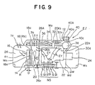
- the partition member 26A of the nearly sealed engine room section 30a has a plurality of blowoff bores 26b in the upper portion thereof, as shown in Fig. 9.
- the lower portion of the partition member 26A is formed into a non-bored portion 26c. Therefore, the cooling air, which has been introduced through an outside-air introducing port 1a by actuation of the cooling fan 20 and has cooled the first cooling unit group R, impinges on the non-bored portion 26c of the partition member 26A, then flows upward, and is discharged froman exhaust port 3b.
- the cooling air flowing upward flows along the front surface of the upper portion of the partition member 26A having the blowoff bores 26b, and generates a negative pressure region near the blowoff bores 26b. Because of the negative pressure, the cooling air within the nearly sealed engine room section 30a that has reached high temperature is passed through the blowoff bores 26b, and is discharged from the exhaust port 3b along with the cooling air that has cooled the first cooling unit group R. Therefore, air within the nearly sealed engine room section 30a can be efficiently ventilated.
- the rear surface, on the engine side, of the partition member 26A are provided with the guide members 26R as in the first embodiment shown in Figs. 2 and 3, the ventilation efficiency can be further enhanced.
- the nearly sealed engine room section 30a is provided with an ejector EJ, as shown in Fig. 9. Because of the ejector EJ, the cooling effect within the nearly sealed engine room section 30a can be enhanced and the leakage of noise generated in the engine 22 and hydraulic pump 24 within the nearly sealed engine room section 30a can be reduced.
- a muffler 38 is connected to the exhaust tube 40 of the engine 22, and there is provided an upper partition wall Wa (or an engine hood) which constitutes part of the cover 1 of the nearly sealed engine room section 30a in which the exit port 40a of the muffler 38 is disposed.
- the ejector EJ (which consists of an outer tube and an inner tube to be described later and ejects the heated air within the nearly sealed engine room section 30a to the outside by employing the exhaust pressure in the engine 22 that is discharged to the outside) is provided in part of the upper partition wall Wa, the nearly sealed engine room section 30a, the engine 22, etc., can be more effectively cooled and the cooling efficiency can be enhanced.
- the ejector EJ is constructed of an exit port 40a of an exhaust tube (inner tube) 40 extending from the muffler 38; an ejector tube 40A which surrounds the exit port 40a and extends from the upper partition wall Wa beyond the exit port 40a; and an ejector gap 40c, formed between the exit port 40a and the ejector tube 40A, which ejects air from the nearly sealed engine room section 30a.
- the bottom partition wall Wd of the nearly sealed engine room section 30a is provided with a plurality of slit intake ports S1 as needed to facilitate the ventilation of the nearly sealed engine room section 30a, the outside air introduced through the intake ports S1 will flow as indicated by arrows EY and therefore the ejector EJ can enhance the cooling efficiency.
- the intake ports S1 are equipped with louvers S, respectively.
- the louvers S constitute noise suppression means NS that suppresses the leakage of engine noise from the nearly sealed engine room section 30a to the outside.
- each louver S is formed by pulling up a plate portion which is left behind when cutting the bottom partition wall Wd to form the intake port S1.
- the noise suppression means NS is constructed so that the intake ports S1, formed into a box shape by a noise intercepting plate NSa, have a silencing effect and that the leakage of engine noise and introduced-air sound from the intake ports S1 to the outside of the nearly sealed engine room section 30a can be suppressed, the noise suppression means NS can further reduce the aforementioned leakage of noise.
- a ventilating fan e.g., an axial flow fan 20K shown in Figs. 8 and 10 and a sirocco fan 20Ks shown in Fig. 9
- the ejector EJ can be suitably disposed, for example, near the supercharger 32 or muffler 38 of the nearly sealed engine room section 30a (which becomes a heat generation source) so that ventilation within the nearly sealed engine room section 30a is facilitated.
- the cooling efficiency can be further enhanced.
- the partition member 26 or 26A is provided to constitute the nearly sealed engine room section 30 or 30a, so the leakage of noise from the engine 22 and the hydraulic pump 24 to the outside can be reduced.
- the first and second embodiments have been described with reference to the case of employing an axial flow fan. However, even if various types of centrifugal fans and bent axis flow fans, including a sirocco fan, are used, the same effect as the first and second embodiments can be obtained.
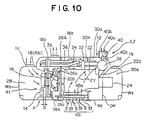
- a sirocco fan 20s is employed as shown in Fig. 10.
- the same reference numerals will be applied to practically the same parts as the first and second embodiments, and a description will be given of points differing from the first and second embodiments.
- the third embodiment as shown in Fig. 10, is equipped with the ejector EJ described in the second embodiment of Fig. 9, but a description will first be made on the assumption that it is not equipped with the ejector EJ.
- the sirocco fan 20s is disposed between a partition member 26A and a first cooling unit group R and is driven by drive means such as an engine 22, a hydraulic motor, an electric motor, etc.
- drive means such as an engine 22, a hydraulic motor, an electric motor, etc.
- the exhaust port 1b described in the first embodiment is provided.
- a guide member g is provided near the outer periphery of the sirocco fan 20s so that part of the cooling air from the sirocco fan 20s is supplied to a nearly sealed engine room section 30a through the communicating bores (suction bores) 26a of the partition member 26A. Therefore, part of the cooling air guided by the guide member g flows toward a muffler 38 and cools a supercharger 32.
- cooling air is introduced through the outside-air introducing port 1a of a cover 1 and then cools the first cooling unit group R. Next, the cooling air flows in the circumferential direction of the sirocco fan 20s and is discharged from the exhaust port 3b. Furthermore, part of the cooling air guided by the guide member g cools the engine 22, the muffler 38, etc., and is discharged from the exhaust port 1b.
- the efficiency of cooling the first cooling unit group R can be enhanced and the leakage of operation noise from the engine 22, the hydraulic pump 24, etc., can be reduced by the nearly sealed engine room section 30a. Furthermore, since the first cooling unit group R can be easily cooled, the operation rate of the above-mentioned construction machine can be enhanced.
- the ejector EJ of the second embodiment is provided as shown in Fig. 10, there is no need to provide the exhaust port 1b. Furthermore, both the ejector EJ and the exhaust port 1b may be disposed. Therefore, if the arrangement of the ejector EJ and the exhaust port 1b is determined according to the aforementioned various objects by design specification, the aforementioned cooling, noise reduction, cleaning, etc., can be more effectively performed.
- the construction machine of the present invention is equipped with a first cooling unit group R consisting of a plurality of cooling units, and a second cooling unit group R1 where some cooling units of the first cooling unit group R are disposed in parallel.
- the remaining cooling unit of the first cooling unit group R is disposed with a gap between itself and the second cooling unit group R1, or is disposed in parallel with the second cooling unit group R1.
- the construction machine is further equipped with a cooling fan disposed so that it faces the cooling units disposed as described above. With this arrangement, cleaning, cooling, and noise reduction can be efficiently performed.
- the present invention is useful as a construction machine that is capable of easily cleaning the cooling units, enhancing the cooling efficiency, and reducing noise.
Abstract
Description
- The present invention relates to a construction machine equipped with an engine and a plurality of cooling units, in which some of the cooling units are disposed in parallel and cooled with a single cooling fan in order to enhance the cooling efficiency, reduce the leakage of operation noise, and facilitate the cooling of the cooling units.
- Construction machines include, for example, a hydraulic shovel that performs a digging operation for a dam, a tunnel, a road, water supply and drainage, etc., or a dismantling operation for constructions, etc.
- The hydraulic shovel is constructed of a lower travel body, an upper swivel body supported on the lower travel body so that it can swivel, and a working unit provided on the front portion of the upper swivel body.
- The upper swivel body is usually provided with a driver's cab. However, there are cases where small hydraulic shovels have not a driver's cab but a driver's seat.
- Furthermore, the frame of the swivel body is provided with an engine, a hydraulic pump, cooling units, batteries, control valves, a fuel tank, a working-oil tank, etc.
- The construction machine performs various operations such as traveling by the lower travel body, swiveling by the upper swivel body, digging by the working unit, etc. These operations are performed by a hydraulic actuator, constructed of a hydraulic motor, a hydraulic cylinder, etc. As shown in Fig. 11, pressure oil is supplied to the hydraulic actuator by the
hydraulic pump 05 that is driven by theengine 03. - In addition, units, such as the
engine 03,radiator 06,hydraulic pump 05, and direction-switching valves for switching the direction of the pressure oil supplied from thehydraulic pump 05, are disposed within the upper swivel body. - The upper swivel body is provided with an
engine room 02 having acover 01. Within theengine room 02, theengine 03 is provided, and theradiator 06 for cooling theengine 03, anoil cooler 010 for cooling working oil, anintercooler 08 for cooling air which is supplied to the combustion chamber of theengine 03, and acondenser 012, are disposed. - The
intercooler 08,oil cooler 010,radiator 06, andcondenser 012 constitute a first cooling unit group R which is used to cool working oil and cooling water. To expose the first cooling unit group R to cooling air and then cool the coolants of the first cooling unit group R, acooling fan 014 is disposed. Thecooling fan 014 is driven by theengine 03. - The
cover 01 that constitutes part of theengine room 02 is provided with outside-air introducing ports 01a for introducing the outside air, and exhaust ports 01b for discharging the introduced air. The introduced air cools the first cooling unit group Rand then theengine 03, thehydraulic pump 05, and the direction switching valves. Thereafter, the air that has reached high temperature is discharged from the exhaust ports 01b to the outside. - With this arrangement, cooling air is introduced through the outside-
air introducing ports 01a. Within theengine room 02, a flow of air occurs as indicated by arrows, cools theengine 02, thehydraulic pump 05, the direction switching valves, etc., and is discharged from the exhaust ports 01b. - As shown in Fig. 11, with respect to the first cooling unit group R provided within the
engine room 02, the cooling air flows in the order ofcondenser 012,intercooler 08,oil cooler 010, andradiator 06 from the upstream side. - The
intercooler 08 is used for cooling air compressed by asupercharger 016 that increases the pressure of the fuel-air mixture in theengine 03. Because of this, afilter unit 017 is provided on the exterior of theengine room 02 to prevent the entry of dust and dirt. - The
supercharger 016 is used to compress introduced air by rotating the turbine with the energy of the exhaust gas of theengine 03. Since the temperature of the introduced air rises due to adiabatic compression, it is necessary to cool the introduced air before it is supplied to theengine 03, for the output of theengine 03 and purification of the exhaust gas. - The introduced air is cooled by the
intercooler 08, and is generally cooled to about 40 to 70°C at the normal temperature. - Since the coolant of the
intercooler 08 has to be cooled to a temperature lower than those of other heat exchangers, and the quantity of the radiant heat of theoil cooler 010 and theradiator 06 is relatively large, theintercooler 08 is generally disposed on the most upstream side of a flow of air, or on the upstream side from theradiator 06. - Since the
supercharger 016 must be disposed on a portion of theengine 03,conduits supercharger 016 and theintercooler 08 and between theintercooler 08 and theengine 03. - For the aforementioned reasons, the aforementioned heat exchange is performed in the order of
condenser 12,intercooler 08,oil cooler 010, andradiator 06, and in order to enhance the cooling efficiency, thecondenser 12, theintercooler 08, theoil cooler 010, and theradiator 06 are disposed in close proximity to one another. However, in construction fields, dust and dirt tend to adhere to thecondenser 012, theintercooler 08, theoil cooler 010, and theradiator 06. If dust and dirt adhere to thecondenser 012, theintercooler 08, theoil cooler 010, and theradiator 06, the aforementioned various operations cannot be continued unless they are frequently cleaned. - In the case where the
intercooler 08, theoil cooler 010, and theradiator 06 are disposed in the recited order, there are cases where, in a narrow space within theengine room 02 of the hydraulic shovel, particularly a narrow space within the engine room of a small hydraulic shovel, rotation of theoil cooler 010 becomes difficult. In the case where theintercooler 08 is disposed so as to face theoil cooler 010 orradiator 06, theintercooler 08 becomes a hindrance and therefore theoil cooler 010 cannot be cleaned. - Hence, the
radiator 06 oroil cooler 010 is made of a lightweight aluminum alloy so that it can be easily lifted upward. Theradiator 06 oroil cooler 010 is first lifted upward to form an open space behind theintercooler 08. Then, theintercooler 08 is cleaned, for example, with an air jet nozzle. The removedradiator 06 oroil cooler 010 is also cleaned, and is returned to the original position. - Because the air suction and exhaust tubes of the
intercooler 08 are large in diameter and are generally fixed on the upper swivel body, the aforementioned operation becomes necessary. - In addition, in the conventional construction machine shown in Fig. 11, the first cooling unit group R, the
engine 03, and thehydraulic pump 05 are disposed in a cooling-air passage which is widely communicated through a core having the area of the wide cooling-air passage of the cooling units within theengine room 02. Therefore, there is a fear that noise generated by theengine 03 and thecooling fan 014 will be transmitted from the wide area to the outside. - In the conventional construction machine, if the first cooling unit group R is not cleaned, the
cooling fan 014 will be clogged by dust and dirt. As a result, the circulation of the cooling air for the first cooling unit group R is reduced and the cooling efficiency becomes low. Because of this, the performance of the construction machine cannot be sufficiently utilized. In addition, to clean theradiator 06 oroil cooler 010, removing and installing theradiator 06 oroil cooler 010 require labor and time, resulting in a reduction in the operation efficiency. Furthermore, as described above, there is a fear that noise will be transmitted to the outside of the construction machine. - The present invention has been made in view of the problems mentioned above. Accordingly, it is the primary object of the present invention to provide a construction machine that is capable of easily cleaning the cooling units, enhancing the cooling efficiency, and reducing noise. The construction machine is equipped with a first cooling unit group consisting of a plurality of cooling units, and a second cooling unit group where some cooling units in the first cooling unit group are disposed in parallel. The remaining cooling unit of the first cooling unit group is disposed with a gap between itself and the second cooling unit group, or is disposed in parallel with the second cooling unit group. The construction machine is further equipped with a cooling fan disposed so that it faces the cooling units disposed as described above.
- To achieve the object of the present invention mentioned above, there is provided a first construction machine comprising: a nearly sealed engine room section where an engine is disposed; a first cooling unit group comprising a plurality of cooling units; and a single cooling fan for cooling a second cooling unit group where some cooling units of the first cooling unit group are disposed in parallel; wherein the second cooling unit group and the cooling fan are disposed so that they face each other.
- With this arrangement, cleaning of the cooling units can be easily performed and the cooling efficiency can be enhanced. In addition, the leakage of engine noise can be reduced.
- In accordance with the present invention, there is provided a construction machine comprising: a first cooling unit group comprising a plurality of cooling units; a cooling fan for cooling a second cooling unit group where some cooling units of the first cooling unit group are disposed in parallel; an engine; a partition member provided between the cooling fan and the engine; a chamber, partitioned and formed by the partition member, where the first cooling unit group and the cooling fan are disposed; and a nearly sealed engine room section, partitioned by the partition member, where the engine is disposed; wherein the cooling fan comprises a single cooling fan.
- With this arrangement, cleaning of the cooling units can be easily performed. In addition, the leakage of engine noise can be reduced and the cooling efficiency can be enhanced.
- In the first and second construction machines of the present invention, the second cooling unit group and the remaining cooling unit of the first cooling unit group are disposed so that they face each other . With this arrangement, the whole of the cooling units can be made compact. In addition, the cooling efficiency can be enhanced with the single cooling fan, and the operation cost can be reduced.
- In the construction machines of the present invention, a gap is provided between the second cooling unit group and the remaining cooling unit so that cleaning can be performed. With this arrangement, dust and dirt on the cooling units can be easily cleaned, for example, by inserting an air jet nozzle into the gap.
- In the construction machines of the present invention, a gap-closing cover is provided to nearly close at least the circumference of the gap and is rotatable or detachable. This can prevent a reduction in the cooling efficiency due to the leakage of the cooling air from the gap. In the case where the rotatable or detachable gap-closing cover is used, the cooling efficiency can be enhanced. In addition, in cleaning the cooling units, the rotatable or detachable gap-closing cover is rotated or removed, and dust and dirt on the cooling unit can be easily cleaned, for example, by inserting an air jet nozzle into the gap.
- In the construction machines of the present invention, the gap D between the second cooling unit group and the remaining cooling unit of the first cooling unit group disposed so as to face the second cooling unit group is set so that a ratio of the gap D to a height H of a cooling unit of the second cooling unit group on the upstream side of the remaining cooling unit is D/H = 0.05 to 0.3. With the ratio D/H, a degree of freedom in designing the gap D and the height H can be increased and the gap D and the height H can be suitably disposed according to design specification.
- In the first and second construction machines of the present invention, the gap D is set to about 30 to 300 mm, preferably about 40 to 100 mm. Because of this, there is an effect that the cooling units can be easily set according to design specification by the gap D.
- In the construction machines of the present invention, the cooling unit of the second cooling unit group on the upstream side of the remaining cooling unit comprises an intercooler. This makes it possible to easily perform cleaning of the cooling units including the intercooler.
- In the construction machine of the present invention, the nearly sealed engine room section is constructed so that cooling air introduced by the cooling fan is drawn in, or is constructed so that it is ventilated by discharging the cooling air within the nearly sealed engine room section, which has risen in temperature, from blowoff bores of the partition member with the cooling air introduced by the cooling fan.
- With this construction, the leakage of noise from the engine to the outside can be effectively reduced.
- In the first and second construction machines of the present invention, the cooling fan comprises an axial flow fan, a bent axis flow fan, or a centrifugal fan. Therefore, by suitably using an axial flow fan, a bent axis flow fan, or a centrifugal fan, the cooling efficiency can be enhanced and the cooling fan can be made compact.
- In the construction machines of the present invention, the nearly sealed engine room section is provided with an ejector. With the ejector, cooling within the nearly sealed engine room section can be efficiently performed.
- In the construction machines of the present invention, the nearly sealed engine room section is provided with an ejector and a ventilating fan. The synergetic effect of the ejector and the ventilating fan can enhance the cooling effect within the nearly sealed engine room section.
- The construction machine of the present invention further comprises cylindrical guide members which have a communicating bore corresponding and communicating with a communicating bore or blowoff bore provided in the partition member. The cylindrical guide members make it possible to enhance the cooling effect within the nearly sealed engine room section.
- The present invention will be described in further detail with reference to the accompanying drawings wherein:
- FIG. 1 is a diagrammatic side view showing a hydraulic shovel to which a construction machine of a first embodiment of the present invention is applied;
- FIG. 2 is a diagrammatic plan view taken along
line 2A-2A in FIG. 1; - FIG. 3 is a diagrammatic end elavational view taken
in the direction of
arrow 3A in FIG. 2; - FIG. 4(A) is an enlarged perspective view showing the cooling units shown in FIG. 3, the radiator being disposed so as to face the oil cooler and the intercooler, disposed in parallel in a vertical direction;
- FIG. 4 (B) is an enlarged perspective view showing the state in which the oil cooler has been rotated so that the intercooler can be cleaned;
- FIG. 5 is an enlarged perspective view showing a first modification of the first embodiment shown in FIG. 4(A);
- FIG. 6 (A) is an enlarged perspective view showing a second modification of the first embodiment shown in FIG. 5, the radiator and the oil cooler being disposed in parallel and the intercooler being disposed with a gap between itself and them;
- FIG. 6 (B) is an enlarged perspective view showing another example of the gap-closing cover shown in FIG. 6(A);
- FIG. 6(C) is an enlarged perspective view showing the case where two gap-closing covers are provided on the upper and lower portions of the intercooler;
- FIG. 6(D) is an enlarged perspective view showing the case where the gap-closing cover is detachably provided on the top surface of the intercooler;
- FIG. 7 is an enlarged perspective view showing a third modification of the first embodiment shown in FIG. 6(A);
- FIG. 8 is a diagrammatic plan view showing a construction machine according to a second embodiment of the present invention;
- FIG. 9 is a diagrammatic end elavational view taken
in the direction of
arrow 9A in FIG. 8; - FIG. 10 is a diagrammatic end elavational view showing a construction machine according to a third embodiment of the present invention; and
- FIG. 11 is a vertical transverse sectional view showing the engine room of a conventional hydraulic shovel.
-
- Embodiments of the present invention will hereinafter be described with reference to the drawings.
- Fig. 1 shows a hydraulic shovel to which a construction machine of a first embodiment of the present invention is applied.
- The hydraulic shovel P of the first embodiment of the present invention, as shown in Fig. 1, is constructed of an
upper swivel body 2, alower travel body 4, and a workingunit 6. - The front end portion of the
upper swivel body 2 is provided with a driver'scab 8, and the rear end portion is provided with acounterweight 10. Furthermore, a suction-type engine room 12, as shown in Figs. 2 and 3, is provided on the frame of theupper swivel body 2 and disposed in front of thecounterweight 10 of the hydraulic shovel P. - Within this
engine room 12, there is provided a first cooling unit group R, which consists of anintercooler 14, anoil cooler 16, and aradiator 18. - The
oil cooler 16 and theintercooler 14 in the first cooling unit group R are disposed in parallel in a vertical direction and constitute a second cooling unit group R1. Theradiator 18, which is the remaining cooling unit RN of the first cooling unit group R, is disposed on the downstream side of the second cooling unit group R1. Theoil cooler 16 is disposed in close proximity to the upper portion of theradiator 18. Theintercooler 14 is disposed in closeproximity to the lower portion of theoil cooler 16 with the gap D between theintercooler 14 and theradiator 18, determined by design specification. - In addition, as shown in Figs. 2 and 3, a
single cooling fan 20 is provided on the downstream side of the first cooling unit group R disposed within theengine room 12 and is used to cool the first cooling unit group R. - Furthermore, an
engine 22 and ahydraulic pump 24 connected to theengine 22 are provided behind the coolingfan 20. Between theengine 22 and thehydraulic pump 24, there is provided a partition plate DW. - A
partition member 26 is provided between the coolingfan 20 and theengine 22. Within achamber 28 partitioned and formed by thepartition member 26, the first cooling unit group R and the coolingfan 20 are disposed. Within a nearly sealedengine room section 30, partitioned by thepartition member 26 and nearly sealed, theengine 22 and thehydraulic pump 24 are disposed. The aforementioned second cooling unit group R1 (theintercooler 14 and the oil cooler 17 in the first embodiment) and the remaining cooling unit RN (theradiator 18 in the first embodiment) of the first cooling unit group R are disposed so as to face each other, and are cooled by thesingle cooling fan 20. - A plurality of
guide members 26R are provided on the downstream side of the partition member 26 (back surface of the partition member 26). Eachguide member 26R is formed in cylindrical form by guide pieces 26R1, 26R2 provided around a communicatingbore 26a formed in thepartition member 26. In the first embodiment, theguide member 26R is square in cross section. - This
guide member 26R has at least the size of the communicatingbore 26a formed in thepartition member 26. It is preferable that theguide member 26R be a communicating bore larger than the communicatingbore 26a. - In the case where a
supercharger 32 is provided in theengine 22, as shown in Fig. 3,conduits supercharger 32 and theintercooler 14 and between theintercooler 14 and theengine 22, respectively. Theconduits partition member 26, the radially outer portion of theradiator 18, and apartition plate 18a. Thepartition plate 18a is provided between an upper partition wall (engine hood) Wa, a front partition wall Wb, a rear partition wall Wc, and a bottom partition wall Wd which constitute acover 1. Thecover 1 constitutes theengine room 12. Thecover 1 further has side partition walls Ws, Ws between the front partition wall Wb and the rear partition wall Wc. -
Amuffler 38 connected to an exhaust port is provided on the rear upper portion of theengine 22 so that exhaust gas is discharged from theengine 22 through anexhaust pipe 40. In addition, part of the exhaust gas is supplied to thesupercharger 32 through anexhaust pipe 32a to drive thesupercharger 32. - As shown in Figs. 4(A) and 4(B), the
oil cooler 16, for example, is constructed so that it is rotatable on a rotation axis AX through ahinge mechanism 44 provided between theoil cooler 16 and the radiator 18 (or the upper swivel body 2). Theconduits oil cooler 16 are connected throughrotatable tube fittings tube fittings 21 are rotatable coaxially with the rotation axis AX and provided on a working-oil supply side and a working-oil exhaust side. Therefore, even if theoil cooler 16 rotates, theconduits - The suction-type nearly sealed
engine room section 30 of the first embodiment is constructed as described above. Therefore, if theengine 22 and the coolingfan 20 are operated, cooling air is introduced through the outside-air introducing port 1a of thecover 1 and then cools the first cooling unit group R. Thereafter, the cooling air passes through the communicatingbores 26a of thepartition member 26 and through theguide members 26R, is introduced into the nearly sealedengine room section 30, and cools theengine 22, themuffler 38, etc. After that, the cooling air is discharged from an exhaust port 1b provided on thecover 1. - In this manner, the
radiator 18, theoil cooler 16, and theintercooler 14 are efficiently cooled with thesingle cooling fan 20. However, cleaning of the first cooling unit group R must be frequently performed. For example, particularly, in a construction site where dismantling of a structure is performed, cleaning of the first cooling unit group R must be performed every day, or a plurality of times a day as occasion demands. - In performing the above-mentioned cleaning operation, the construction of the first cooling unit group R of the first embodiment is useful.
- That is, the
oil cooler 16 of the second cooling unit group R1 (oil cooler 16 and intercooler 14) of the first cooling unit group R (radiator 18,oil cooler 16, and intercooler 14) is rotatable as shown in Fig. 4(B) through thehinge mechanism 44 with respect to the remaining cooling unit RN (radiator 18) of the first cooling unit group R so that an open space can be formed above the top surface of theintercooler 14. Therefore, theintercooler 14 and theradiator 18 can be easily cleaned by inserting an air jet nozzle into the gap between theradiator 18 and theintercooler 14 and then jetting air. Similarly, theoil cooler 16 and theradiator 18 in the open states can be easily cleaned with a jet of air. - After the cleaning, the
oil cooler 16 is returned to its original position, as shown in Fig. 4(A). Theoil cooler 16 can be easily and detachably fastened by engagingthumbscrews 48a with the engagingbolt 48 of ahinge mechanism 46 that is used as a stopper member provided between theoil cooler 16 and theintercooler 14. - The gap D between the
intercooler 14 and at least one cooling unit (radiator 18 in the first embodiment) of the first cooling unit group R is suitably determined by design specification. For instance, the gap D is determined so that a ratio of D/H becomes about 0.05 to 0.3. The letter H in the ratio of D/H represents the height of theintercooler 14 that faces at least one cooling unit (radiator 18 in the first embodiment) of the first cooling unit group R. - The gap D is usually set to about 30 to 200 mm. In the case of large machine types and special machine types, the gape D is set to about 30 to 300 mm. It is preferable that the gap D be set to about 40 to 100 mm.
- In the first embodiment, the
intercooler 14 is disposed so that it faces one cooling unit of the first cooling unit group R. However, the cooling unit that faces one cooling unit of the first cooling unit group R is not limited to theintercooler 14. In the case where two other cooling units in the first cooling unit group R are disposed so that they face each other, the same effect as the first embodiment can be obtained, if the aforementioned gap D is provided between the two cooling units. - Next, a first modification of the first embodiment shown in Fig. 4 will be described with reference to Fig. 5. The same reference numerals will be applied to practically the same parts as the first embodiment, and a description will be given of points differing from the first embodiment.
- In the first modification, with the gap D between the
radiator 18 of the second cooling unit group R1 (oil cooler 16 and radiator 18) and the remaining cooling unit RN (intercooler 14) of the first cooling unit group R (oil cooler 16,radiator 18, and intercooler 14), the remaining cooling unit RN (intercooler 14) of the first cooling unit group R is disposed as shown in Fig. 5. Furthermore, acondenser 19 for an air conditioner is disposed with the gap D between itself and theoil cooler 16. - As with the first embodiment, cooling can be performed with the
single cooling fan 20. Therefore, the operation costs can be reduced. In addition, cleaning can be easily performed by inserting the aforementioned air jet nozzle into the gap D between theintercooler 14 and theradiator 18 and the gap D between theoil cooler 16 and thecondenser 19 and then jetting air. Therefore, the operation efficiency can be enhanced. - Next, a second modification of the first embodiment shown in Fig. 5 will be described with reference to Fig. 6. The same reference numerals will be applied to practically the same parts as the first embodiment, and a description will be given of points differing from the first embodiment.
- In the second modification, with the gap D between the second cooling unit group R1 (
oil cooler 16 and radiator 18) and the remaining cooling unit RN (intercooler 14) of the first cooling unit group R (oil cooler 16,radiator 18, and intercooler 14), the remaining cooling unit RN (intercooler 14) of the first cooling unit group R is disposed as shown in Fig. 6(A). - As with the first embodiment, cooling can be performed with the
single cooling fan 20. Therefore, the operation costs can be reduced. In addition, cleaning can be easily performed by inserting the aforementioned air jet nozzle into the gap D between the second cooling unit group R1 (oil cooler 16 and radiator 18) and the remaining cooling unit RN (intercooler 14) and then jetting air. Therefore, the operation efficiency can be enhanced. - In the first embodiment and the first and second modifications shown in Figs. 2 to 6(A), if gap-closing covers CV are provided to nearly close at least the circumference of the gap D shown in Fig. 6(A), or if rotatable or detachable gap-closing covers CV of elastic material are provided along the perimeter of the
intercooler 14 so that they are detachable or rotatable withfemale screws 48a, a reduction in the cooling efficiency due to the leakage of cooling air from the gap D can be prevented. - In the case where rotatable or detachable gap-closing covers CV are provided, the cooling efficiency can be enhanced. In addition, if the rotatable or detachable gap-closing covers CV are rotated or removed when cleaning is performed, dust and dirt on the cooling units can be easily cleaned, for example, by inserting an air jet nozzle into the gap D.
- Other examples of the mounting structure for the gap-closing cover CV shown in Fig. 6(A) will be described with reference to Figs. 6(B) to 6(D).
- In the example shown in Fig. 6(B), brackets RS2 extend from a frame RS1 attached to the
radiator 18 and theoil cooler 16 and are attached to theintercooler 14. One end of a gap-closing cover CV is rotatably attached to the frame RS1 through hinges CVh, while the other end is detachably attached to theintercooler 14 bythumbscrews 48a. In this way, a plurality of gap-closing covers CV are disposed along the outer perimeter of theintercooler 14 so that the aforementioned gap D is closed. - In the example of Fig. 6(C), the aforementioned gap-closing covers CV are provided on the top surface and bottom surface of the
intercooler 14. This structure is employed when the aforementioned gap D is small. In this case, cost reduction can be achieved. - In the example of Fig. 6(D), the aforementioned gap-closing covers CV are detachably attached to the outer perimeter of the
intercooler 14 bythumbscrews 48a so that the aforementioned gap D is closed. - In addition, if the gap-closing covers CV described in Fig. 6 are provided to close the gap D shown in Figs. 2 to 5, the leakage of the aforementioned cooling air from the gap D will be prevented and therefore the cooling efficiency can be enhanced.
- Next, a third modification of the first embodiment shown in Fig. 6(A) will be described with reference to Fig. 7. The same reference numerals will be applied to practically the same parts as the first embodiment, and a description will be given of points differing from the first embodiment.
- In the third modification, the aforementioned second cooling unit group R1, in which some cooling units in the aforementioned first cooling unit group R (
intercooler 14,oil cooler 16,radiator 18, and condenser 19) are disposed in parallel, consists of anintercooler 14, anoil cooler 16, and aradiator 18. - The remaining cooling unit (condenser 19) RN of the first cooling unit group R is provided on a suitable place on the second cooling unit group R1 disposed as shown in Fig. 6.
- As with the first embodiment, the
intercooler 14, theoil cooler 16, and theradiator 18 can be cooled with thesingle cooling fan 20. Therefore, the operation costs can be reduced. In addition, theintercooler 14, theoil cooler 16, and theradiator 18 are individually disposed. Because of this, they can be easily cleaned by jetting air directly to them, without performing rotation and providing the gap D as in the aforementioned cases. Therefore, the operation efficiency can be enhanced. - The second embodiment of the present invention will be described with reference to Figs. 8 and 9. The same reference numerals will be applied to practically the same parts as the first embodiment, and a description will be given of points differing from the first embodiment.
- The arrangement of the cooling units in the second embodiment is the same as the first embodiment shown in Fig. 4. Therefore, the engine room of the second embodiment constitutes a blowoff-type nearly sealed
engine room section 30a, as shown in Figs. 8 and 9. - The
partition member 26A of the nearly sealedengine room section 30a has a plurality of blowoff bores 26b in the upper portion thereof, as shown in Fig. 9. The lower portion of thepartition member 26A is formed into anon-bored portion 26c. Therefore, the cooling air, which has been introduced through an outside-air introducing port 1a by actuation of the coolingfan 20 and has cooled the first cooling unit group R, impinges on thenon-bored portion 26c of thepartition member 26A, then flows upward, and is discharged froman exhaust port 3b. - The cooling air flowing upward flows along the front surface of the upper portion of the
partition member 26A having the blowoff bores 26b, and generates a negative pressure region near the blowoff bores 26b. Because of the negative pressure, the cooling air within the nearly sealedengine room section 30a that has reached high temperature is passed through the blowoff bores 26b, and is discharged from the exhaust port 3b along with the cooling air that has cooled the first cooling unit group R. Therefore, air within the nearly sealedengine room section 30a can be efficiently ventilated. In addition, if the rear surface, on the engine side, of thepartition member 26A are provided with theguide members 26R as in the first embodiment shown in Figs. 2 and 3, the ventilation efficiency can be further enhanced. - In the second embodiment, the nearly sealed
engine room section 30a is provided with an ejector EJ, as shown in Fig. 9. Because of the ejector EJ, the cooling effect within the nearly sealedengine room section 30a can be enhanced and the leakage of noise generated in theengine 22 andhydraulic pump 24 within the nearly sealedengine room section 30a can be reduced. - Now, a description will be given of the ejector EJ. In the exhaust system of the
engine 22, amuffler 38 is connected to theexhaust tube 40 of theengine 22, and there is provided an upper partition wall Wa (or an engine hood) which constitutes part of thecover 1 of the nearly sealedengine room section 30a in which the exit port 40a of themuffler 38 is disposed. - If the ejector EJ (which consists of an outer tube and an inner tube to be described later and ejects the heated air within the nearly sealed
engine room section 30a to the outside by employing the exhaust pressure in theengine 22 that is discharged to the outside) is provided in part of the upper partition wall Wa, the nearly sealedengine room section 30a, theengine 22, etc., can be more effectively cooled and the cooling efficiency can be enhanced. - The ejector EJ is constructed of an exit port 40a of an exhaust tube (inner tube) 40 extending from the
muffler 38; anejector tube 40A which surrounds the exit port 40a and extends from the upper partition wall Wa beyond the exit port 40a; and anejector gap 40c, formed between the exit port 40a and theejector tube 40A, which ejects air from the nearly sealedengine room section 30a. - If the bottom partition wall Wd of the nearly sealed
engine room section 30a is provided with a plurality of slit intake ports S1 as needed to facilitate the ventilation of the nearly sealedengine room section 30a, the outside air introduced through the intake ports S1 will flow as indicated by arrows EY and therefore the ejector EJ can enhance the cooling efficiency. - The intake ports S1 are equipped with louvers S, respectively. The louvers S constitute noise suppression means NS that suppresses the leakage of engine noise from the nearly sealed
engine room section 30a to the outside. As shown in Fig. 9, each louver S is formed by pulling up a plate portion which is left behind when cutting the bottom partition wall Wd to form the intake port S1. - If the noise suppression means NS is constructed so that the intake ports S1, formed into a box shape by a noise intercepting plate NSa, have a silencing effect and that the leakage of engine noise and introduced-air sound from the intake ports S1 to the outside of the nearly sealed
engine room section 30a can be suppressed, the noise suppression means NS can further reduce the aforementioned leakage of noise. - Since negative pressure occurs around the engine exhaust air ejected from the exit port 40a of the
exhaust tube 40 of theengine 22, the pressure near theejector gap 40c becomes negative. Therefore, the air within the nearly sealedengine room section 30a, along with heat, can be forcibly discharged to the outside by pump action caused by the negative pressure. - Although not shown, a ventilating fan (e.g., an
axial flow fan 20K shown in Figs. 8 and 10 and a sirocco fan 20Ks shown in Fig. 9), along with the ejector EJ, can be suitably disposed, for example, near thesupercharger 32 ormuffler 38 of the nearly sealedengine room section 30a (which becomes a heat generation source) so that ventilation within the nearly sealedengine room section 30a is facilitated. In this case, the cooling efficiency can be further enhanced. - In the first and second embodiments, the
partition member engine room section engine 22 and thehydraulic pump 24 to the outside can be reduced. - The first and second embodiments have been described with reference to the case of employing an axial flow fan. However, even if various types of centrifugal fans and bent axis flow fans, including a sirocco fan, are used, the same effect as the first and second embodiments can be obtained.
- A description will be given of a third embodiment of the present invention using the above-mentioned sirocco fan.
- For instance, instead of the
axial flow fan 20 of the second embodiment shown in Fig. 9, a sirocco fan 20s is employed as shown in Fig. 10. The same reference numerals will be applied to practically the same parts as the first and second embodiments, and a description will be given of points differing from the first and second embodiments. - The third embodiment, as shown in Fig. 10, is equipped with the ejector EJ described in the second embodiment of Fig. 9, but a description will first be made on the assumption that it is not equipped with the ejector EJ.
- As shown in Fig. 10, the sirocco fan 20s is disposed between a
partition member 26A and a first cooling unit group R and is driven by drive means such as anengine 22, a hydraulic motor, an electric motor, etc. In addition to an exhaust port 3b, the exhaust port 1b described in the first embodiment is provided. - In the third embodiment, a guide member g is provided near the outer periphery of the sirocco fan 20s so that part of the cooling air from the sirocco fan 20s is supplied to a nearly sealed
engine room section 30a through the communicating bores (suction bores) 26a of thepartition member 26A. Therefore, part of the cooling air guided by the guide member g flows toward amuffler 38 and cools asupercharger 32. - In the third embodiment constructed as described above, if the
engine 22 and the sirocco fan 20s are operated, cooling air is introduced through the outside-air introducing port 1a of acover 1 and then cools the first cooling unit group R. Next, the cooling air flows in the circumferential direction of the sirocco fan 20s and is discharged from the exhaust port 3b. Furthermore, part of the cooling air guided by the guide member g cools theengine 22, themuffler 38, etc., and is discharged from the exhaust port 1b. - In addition , if the sirocco fan 20s is replaced with the
axial flow fan 20 of the second embodiment shown in Fig. 9, the same operational effect as the second embodiment can be obtained. - Therefore, in the third embodiment, the efficiency of cooling the first cooling unit group R can be enhanced and the leakage of operation noise from the
engine 22, thehydraulic pump 24, etc., can be reduced by the nearly sealedengine room section 30a. Furthermore, since the first cooling unit group R can be easily cooled, the operation rate of the above-mentioned construction machine can be enhanced. - If the ejector EJ of the second embodiment is provided as shown in Fig. 10, there is no need to provide the exhaust port 1b. Furthermore, both the ejector EJ and the exhaust port 1b may be disposed. Therefore, if the arrangement of the ejector EJ and the exhaust port 1b is determined according to the aforementioned various objects by design specification, the aforementioned cooling, noise reduction, cleaning, etc., can be more effectively performed.
- While the present invention has been described with reference to the embodiments applied to a transverse engine, the invention is not to be limited to the transverse engine, but may be modified within the scope of the invention hereinafter claimed. For example, in the case where the present invention is applied to a vertical engine, various changes may be made where appropriate. In addition, numerous changes may be made according to changes in the conditions determined by design specification, or according to machine specification, etc.
- The construction machine of the present invention, as described above, is equipped with a first cooling unit group R consisting of a plurality of cooling units, and a second cooling unit group R1 where some cooling units of the first cooling unit group R are disposed in parallel. The remaining cooling unit of the first cooling unit group R is disposed with a gap between itself and the second cooling unit group R1, or is disposed in parallel with the second cooling unit group R1. The construction machine is further equipped with a cooling fan disposed so that it faces the cooling units disposed as described above. With this arrangement, cleaning, cooling, and noise reduction can be efficiently performed. Thus, the present invention is useful as a construction machine that is capable of easily cleaning the cooling units, enhancing the cooling efficiency, and reducing noise.
Claims (13)
- A construction machine comprising:wherein said second cooling unit group (R1) and said cooling fan (20) are disposed so that they face each other.a nearly sealed engine room section (30, 30a) where an engine (22) is disposed;a first cooling unit group (R) comprising a plurality of cooling units; anda single cooling fan (20) for cooling a second cooling unit group (R1) where some cooling units of said first cooling unit group (R) are disposed in parallel;
- A construction machine comprising:wherein said cooling fan (20) comprises a single cooling fan (20).a first cooling unit group (R) comprising a plurality of cooling units;a cooling fan (20) for cooling a second cooling unit group (R1) where some cooling units of said first cooling unit group (R) are disposed in parallel;an engine (20);a partition member (26, 26A) provided between said cooling fan (20) and said engine (20);a chamber (28), partitioned and formed by said partition member (26, 26A), where said first cooling unit group (R) and said cooling fan (20) are disposed; anda nearly sealed engine room section (30, 30a), partitioned by said partition member (26, 26A), where said engine (22) is disposed;
- The construction machine as set forth in claim 1 or 2, wherein said second cooling unit group (R1) and the remaining cooling unit (RN) of said first cooling unit group (R) are disposed so that they face each other.
- The construction machine as set forth in claim 3, wherein a gap (D) is provided between said second cooling unit group (R1) and said remaining cooling unit (RN) so that cleaning can be performed.
- The construction machine as set forth in claim 4, wherein a gap-closing cover (CV) is provided to nearly close at least the circumference of said gap (D) and is rotatable or detachable.
- The construction machine as set forth in any one of claims 1 through 5, wherein a gap (D) between said second cooling unit group (R1) and the remaining cooling unit (RN) of said first cooling unit group (R) disposed so as to face said second cooling unit group (R1) is set so that a ratio of said gap (D) to a height (H) of a cooling unit of said second cooling unit group (R1) on the upstream side of said remaining cooling unit (RN) is (D/H) = 0.05 to 0.3.
- The construction machine as set forth in claim 6, wherein said gap (D) is set to about 30 to 300 mm, preferably about 40 to 100 mm.
- The construction machine as set forth in claim 6 or 7, wherein said cooling unit of said second cooling unit group (R1) on the upstream side of said remaining cooling unit (RN) comprises an intercooler (14).
- The construction machine as set forth in claim 2, 4, or 6, wherein said nearly sealed engine room section (30, 30a) is constructed so that cooling air introduced by said cooling fan (20) is drawn in, or is constructed so that it is ventilated by discharging cooling air within said nearly sealed engine room section (30, 30a), which has risen in temperature, fromblowoff bores (26b) of said partition member (26, 26A) with cooling air introduced by said cooling fan (20).
- The construction machine as set forth in claim 1, 2, or 9, wherein said cooling fan (20) comprises an axial flow fan, a bent axis flow fan, or a centrifugal fan.
- The construction machine as set forth in claim 1, 2, or 9, wherein said nearly sealed engine room section (30, 30a) is provided with an ejector (EJ).
- The construction machine as set forth in claim 1, 2, 9, or 11, wherein said nearly sealed engine room section (30, 30a) is provided with an ejector (EJ) and a ventilating fan (20K, 20Ks).
- The construction machine as set forth in claim 1, 2, 6, 7, 9, 11, or 12, further comprising cylindrical guide members (26R) which have a communicating bore corresponding and communicating with a communicating bore (26a) or blowoff bore (26b) provided in said partition member (26, 26a).
Applications Claiming Priority (3)
| Application Number | Priority Date | Filing Date | Title |
|---|---|---|---|
| JP2000166782 | 2000-06-02 | ||
| JP2000166782A JP2001348909A (en) | 2000-06-02 | 2000-06-02 | Construction machinery |
| PCT/JP2001/002399 WO2001094706A1 (en) | 2000-06-02 | 2001-03-26 | Construction machinery |
Publications (2)
| Publication Number | Publication Date |
|---|---|
| EP1295995A1 true EP1295995A1 (en) | 2003-03-26 |
| EP1295995A4 EP1295995A4 (en) | 2009-03-11 |
Family
ID=18670051
Family Applications (1)
| Application Number | Title | Priority Date | Filing Date |
|---|---|---|---|
| EP01915770A Withdrawn EP1295995A4 (en) | 2000-06-02 | 2001-03-26 | Construction machinery |
Country Status (4)
| Country | Link |
|---|---|
| US (1) | US6622668B2 (en) |
| EP (1) | EP1295995A4 (en) |
| JP (1) | JP2001348909A (en) |
| WO (1) | WO2001094706A1 (en) |
Cited By (4)
| Publication number | Priority date | Publication date | Assignee | Title |
|---|---|---|---|---|
| WO2010074638A1 (en) * | 2008-12-22 | 2010-07-01 | Atlas Copco Rock Drills Ab | Cooling system for cooling of at least one circulating fluid, and a machine comprising the cooling system |
| CN103216303A (en) * | 2013-04-16 | 2013-07-24 | 佛山神威热交换器有限公司 | Box body type heat radiator |
| WO2018210388A1 (en) * | 2017-05-16 | 2018-11-22 | Nilfisk A/S | Cooling of casing with propulsion motor for utility vehicle |
| EP3705631A1 (en) * | 2019-03-08 | 2020-09-09 | Wacker Neuson Linz GmbH | Working machine with electric drive and cooling device |
Families Citing this family (49)
| Publication number | Priority date | Publication date | Assignee | Title |
|---|---|---|---|---|
| ITTO20020727A1 (en) * | 2002-08-14 | 2004-02-15 | Fiat Kobelco Construction Machinery Spa | COOLING EQUIPMENT FOR A VEHICLE, IN PARTICULAR FOR AN EXCAVATOR. |
| CN1642764A (en) * | 2002-12-13 | 2005-07-20 | 新卡特彼勒三菱株式会社 | Cooling device for construction machines |
| ITTO20030127A1 (en) | 2003-02-21 | 2004-08-22 | Same Deutz Fahr Group Spa | COOLING SYSTEM FOR AN AGRICULTURAL MACHINE. |
| CN1806103B (en) * | 2003-06-16 | 2011-06-15 | 神钢建设机械株式会社 | Construction machine |
| KR101127799B1 (en) * | 2004-12-29 | 2012-03-26 | 두산산업차량 주식회사 | Cooler for engine type forklift truck |
| JP4548375B2 (en) * | 2006-03-30 | 2010-09-22 | コベルコ建機株式会社 | Work machine |
| SE530034C2 (en) * | 2006-06-30 | 2008-02-12 | Scania Cv Abp | Cooling device for a motor vehicle |
| CN101209669B (en) * | 2006-12-30 | 2012-05-16 | 卡特彼勒公司 | Cooling system of heat exchanger row row with strategical arrangement |
| JP4900163B2 (en) * | 2007-09-26 | 2012-03-21 | コベルコ建機株式会社 | Construction machinery |
| US8230957B2 (en) * | 2008-01-30 | 2012-07-31 | Deere & Company | Flow-inducing baffle for engine compartment ventilation |
| US20090194352A1 (en) * | 2008-01-31 | 2009-08-06 | Sean Plante | Movable Side-By-Side Cooling Package |
| KR100974278B1 (en) * | 2008-03-18 | 2010-08-06 | 볼보 컨스트럭션 이키프먼트 홀딩 스웨덴 에이비 | engine room of construction equipment |
| WO2009142555A1 (en) * | 2008-05-23 | 2009-11-26 | Volvo Construction Equipment Ab | Ventilating system for ventilating an engine space in vehicle, a vehicle comprising the ventilating system and a work machine comprising the ventilating system |
| US8672089B2 (en) * | 2008-11-27 | 2014-03-18 | Caterpillar (Ni) Limited | Baffle arrangement for a genset enclosure |
| US8807113B2 (en) * | 2009-05-04 | 2014-08-19 | Ford Global Technologies, Llc | Device and method for integrating an air cleaner into a radiator fan shroud |
| JP5234693B2 (en) * | 2009-10-16 | 2013-07-10 | 日立建機株式会社 | Construction machinery |
| JP5699653B2 (en) * | 2010-03-08 | 2015-04-15 | コベルコ建機株式会社 | Construction machine cooling structure |
| EP2426334B1 (en) * | 2010-09-01 | 2017-10-25 | CLAAS Tractor SAS | Cooling arrangement for an agricultural vehicle |
| US8556014B2 (en) * | 2010-11-03 | 2013-10-15 | Caterpillar Inc. | Diesel particulate filter packaging and method of directing airflow in a skid steer machine |
| JP5160668B2 (en) * | 2011-06-17 | 2013-03-13 | 株式会社小松製作所 | Excavator |
| JP5831111B2 (en) * | 2011-10-03 | 2015-12-09 | コベルコ建機株式会社 | Exhaust structure of construction machinery |
| US9255381B2 (en) * | 2011-12-26 | 2016-02-09 | Hitachi Construction Machinery Co., Ltd. | Construction machine |
| CN103184922B (en) * | 2011-12-27 | 2015-04-22 | 井关农机株式会社 | Driving part structure of working vehicle |
| US8752522B1 (en) * | 2012-03-14 | 2014-06-17 | Asaf Cohen | Compact multi-unit vehicle cooling system |
| JP5181076B1 (en) * | 2012-08-03 | 2013-04-10 | 株式会社小松製作所 | Excavator |
| DE202013101570U1 (en) | 2013-04-12 | 2014-07-14 | Autokühler GmbH & Co KG | Cooling module for internal combustion engines |
| JP2015021398A (en) * | 2013-07-16 | 2015-02-02 | キャタピラー エス エー アール エル | Machine body and work machine |
| JP5819891B2 (en) * | 2013-08-21 | 2015-11-24 | 日立建機株式会社 | Construction machinery |
| BR112016014141B1 (en) * | 2013-12-19 | 2021-09-14 | Volvo Truck Corporation | EXHAUST GAS TREATMENT SYSTEM TO BE INSTALLED IN A CHASSIS OF AN AUTOMOTIVE VEHICLE; ENGINE AND AUTOMOTIVE VEHICLE ARRANGEMENT |
| JP6040187B2 (en) * | 2014-02-24 | 2016-12-07 | 日立建機株式会社 | Construction machinery |
| JP6415890B2 (en) | 2014-08-04 | 2018-10-31 | 株式会社クボタ | Work vehicle |
| WO2016027307A1 (en) * | 2014-08-19 | 2016-02-25 | 株式会社小松製作所 | Work vehicle |
| US9581071B2 (en) * | 2014-09-25 | 2017-02-28 | Hyster-Yale Group, Inc. | Cooling system for industrial vehicle |
| US10384532B2 (en) | 2015-03-06 | 2019-08-20 | Komatsu Ltd. | Work vehicle |
| JP2017002509A (en) * | 2015-06-08 | 2017-01-05 | 株式会社神戸製鋼所 | Cooling structure for construction machine |
| JP6229694B2 (en) * | 2015-06-08 | 2017-11-15 | コベルコ建機株式会社 | Construction machine with engine |
| JP6556566B2 (en) * | 2015-09-07 | 2019-08-07 | 日野自動車株式会社 | Vehicle cooling system |
| JP6495193B2 (en) * | 2016-01-20 | 2019-04-03 | 株式会社日立建機ティエラ | Small construction machinery |
| US10569642B2 (en) * | 2016-06-20 | 2020-02-25 | Polaris Industries Inc. | Cooling system for an all terrain vehicle |
| JP6208892B1 (en) * | 2016-08-03 | 2017-10-04 | 株式会社小松製作所 | Work vehicle |
| US10570809B2 (en) * | 2016-09-27 | 2020-02-25 | Ford Global Technologies, Llc | Methods and systems for coolant system |
| CN109072758A (en) | 2017-04-04 | 2018-12-21 | 株式会社小松制作所 | Working truck |
| KR102567146B1 (en) * | 2017-05-31 | 2023-08-18 | 한온시스템 주식회사 | Cooling module for vehicle |
| EP3527799A1 (en) * | 2018-02-20 | 2019-08-21 | Modine Manufacturing Company | Frameless cooling module |
| JP7065642B2 (en) * | 2018-02-28 | 2022-05-12 | 株式会社小松製作所 | Work machine |
| JP6938411B2 (en) * | 2018-03-23 | 2021-09-22 | ヤンマーパワーテクノロジー株式会社 | combine |
| KR20190121117A (en) * | 2018-04-17 | 2019-10-25 | 현대자동차주식회사 | Cooling system for engine |
| JP7076396B2 (en) * | 2019-03-27 | 2022-05-27 | 日立建機株式会社 | Work machine |
| US11428481B2 (en) | 2019-12-05 | 2022-08-30 | Caterpillar Paving Products Inc. | Cooling package cleaning system |
Citations (4)
| Publication number | Priority date | Publication date | Assignee | Title |
|---|---|---|---|---|
| EP0734892A2 (en) * | 1995-03-31 | 1996-10-02 | Fiat-Hitachi Excavators S.p.A. | Cooling structure for construction machine |
| JPH11350530A (en) * | 1998-06-05 | 1999-12-21 | Sumitomo Constr Mach Co Ltd | Cooling device for construction machine |
| JP2000110560A (en) * | 1998-10-08 | 2000-04-18 | Shin Caterpillar Mitsubishi Ltd | Fan revolution speed control method and its device |
| JP2000145455A (en) * | 1998-11-11 | 2000-05-26 | Shin Caterpillar Mitsubishi Ltd | Construction machine cooling system |
Family Cites Families (5)
| Publication number | Priority date | Publication date | Assignee | Title |
|---|---|---|---|---|
| JPH0811551A (en) | 1994-06-27 | 1996-01-16 | Hitachi Constr Mach Co Ltd | Heat exchanging unit of construction machinery |
| JP3023433B2 (en) * | 1995-04-10 | 2000-03-21 | 日立建機株式会社 | Heat exchanger cooling system |
| US6076488A (en) * | 1997-03-17 | 2000-06-20 | Shin Caterpillar Mitsubishi Ltd. | Cooling device for a construction machine |
| US6032620A (en) * | 1997-10-31 | 2000-03-07 | Kabushiki Kaisha Kobe Seiko Sho | Air intake structure in a construction machine |
| EP1028258A4 (en) * | 1998-06-17 | 2002-07-10 | Hitachi Construction Machinery | Fan device and shroud |
-
2000
- 2000-06-02 JP JP2000166782A patent/JP2001348909A/en active Pending
-
2001
- 2001-03-26 EP EP01915770A patent/EP1295995A4/en not_active Withdrawn
- 2001-03-26 WO PCT/JP2001/002399 patent/WO2001094706A1/en active Application Filing
- 2001-03-26 US US10/048,570 patent/US6622668B2/en not_active Expired - Fee Related
Patent Citations (4)
| Publication number | Priority date | Publication date | Assignee | Title |
|---|---|---|---|---|
| EP0734892A2 (en) * | 1995-03-31 | 1996-10-02 | Fiat-Hitachi Excavators S.p.A. | Cooling structure for construction machine |
| JPH11350530A (en) * | 1998-06-05 | 1999-12-21 | Sumitomo Constr Mach Co Ltd | Cooling device for construction machine |
| JP2000110560A (en) * | 1998-10-08 | 2000-04-18 | Shin Caterpillar Mitsubishi Ltd | Fan revolution speed control method and its device |
| JP2000145455A (en) * | 1998-11-11 | 2000-05-26 | Shin Caterpillar Mitsubishi Ltd | Construction machine cooling system |
Non-Patent Citations (1)
| Title |
|---|
| See also references of WO0194706A1 * |
Cited By (4)
| Publication number | Priority date | Publication date | Assignee | Title |
|---|---|---|---|---|
| WO2010074638A1 (en) * | 2008-12-22 | 2010-07-01 | Atlas Copco Rock Drills Ab | Cooling system for cooling of at least one circulating fluid, and a machine comprising the cooling system |
| CN103216303A (en) * | 2013-04-16 | 2013-07-24 | 佛山神威热交换器有限公司 | Box body type heat radiator |
| WO2018210388A1 (en) * | 2017-05-16 | 2018-11-22 | Nilfisk A/S | Cooling of casing with propulsion motor for utility vehicle |
| EP3705631A1 (en) * | 2019-03-08 | 2020-09-09 | Wacker Neuson Linz GmbH | Working machine with electric drive and cooling device |
Also Published As
| Publication number | Publication date |
|---|---|
| EP1295995A4 (en) | 2009-03-11 |
| JP2001348909A (en) | 2001-12-21 |
| US20020104491A1 (en) | 2002-08-08 |
| US6622668B2 (en) | 2003-09-23 |
| WO2001094706A1 (en) | 2001-12-13 |
Similar Documents
| Publication | Publication Date | Title |
|---|---|---|
| US6622668B2 (en) | Construction machinery | |
| US8104559B2 (en) | Multiple air flow paths using single axial fan | |
| JP2000062474A (en) | Cooling device for work vehicle | |
| JP4160454B2 (en) | Engine hood for construction machinery, engine room structure for construction machinery, and engine cooling device for construction machinery | |
| JP2023103214A (en) | Construction machine | |
| JP2003291662A (en) | Construction machine | |
| JP2001329842A (en) | Baffle plate structure for heat exchanger | |
| JPH11254976A (en) | Noise reducing device for construction machine and cover and exhaust part used for this device | |
| JP2004225625A (en) | Cooling system of construction machine | |
| JP2008296615A (en) | Construction machine | |
| JP2004001645A (en) | Construction machine and cooling air duct | |
| JP2002356115A (en) | Cooling device for construction machine | |
| JP3472162B2 (en) | Heat exchanger for construction machinery | |
| JP2002256591A (en) | Construction machine and cooling air duct | |
| JPH11241369A (en) | Cooing device for construction machine | |
| JP2003300421A (en) | Construction machine | |
| JP2002302968A (en) | Construction machine | |
| JP2003049648A (en) | Construction equipment | |
| JPH11241366A (en) | Exhauster for construction machine | |
| JP2003293390A (en) | Construction machinery and cooling air duct | |
| JP2000212996A (en) | Cooling equipment for construction machine | |
| JPH11269920A (en) | Cooling device for construction machine | |
| JP2005126990A (en) | Cooling device of working machine | |
| JP2002302969A (en) | Construction machine and cooling air duct | |
| JP2004003396A (en) | Construction machine |
Legal Events
| Date | Code | Title | Description |
|---|---|---|---|
| PUAI | Public reference made under article 153(3) epc to a published international application that has entered the european phase |
Free format text: ORIGINAL CODE: 0009012 |
|
| 17P | Request for examination filed |
Effective date: 20020227 |
|
| AK | Designated contracting states |
Kind code of ref document: A1 Designated state(s): AT BE CH CY DE DK ES FI FR GB GR IE IT LI LU MC NL PT SE TR Designated state(s): AT BE CH CY DE DK ES FI FR GB GR IE IT LI LU MC NL PT SE TR |
|
| RBV | Designated contracting states (corrected) |
Designated state(s): AT BE CH CY DE FR GB LI |
|
| RAP1 | Party data changed (applicant data changed or rights of an application transferred) |
Owner name: CATERPILLAR JAPAN LTD. |
|
| A4 | Supplementary search report drawn up and despatched |
Effective date: 20090205 |
|
| RIC1 | Information provided on ipc code assigned before grant |
Ipc: E02F 9/08 20060101ALI20090130BHEP Ipc: F01P 3/18 20060101ALI20090130BHEP Ipc: E02F 9/00 20060101AFI20011219BHEP |
|
| STAA | Information on the status of an ep patent application or granted ep patent |
Free format text: STATUS: THE APPLICATION HAS BEEN WITHDRAWN |
|
| 18W | Application withdrawn |
Effective date: 20090324 |