EP1295830A2 - Roll changer and method for the automatic change of rolls during stop - Google Patents
Roll changer and method for the automatic change of rolls during stop Download PDFInfo
- Publication number
- EP1295830A2 EP1295830A2 EP02405806A EP02405806A EP1295830A2 EP 1295830 A2 EP1295830 A2 EP 1295830A2 EP 02405806 A EP02405806 A EP 02405806A EP 02405806 A EP02405806 A EP 02405806A EP 1295830 A2 EP1295830 A2 EP 1295830A2
- Authority
- EP
- European Patent Office
- Prior art keywords
- web
- roll
- work
- working
- path
- Prior art date
- Legal status (The legal status is an assumption and is not a legal conclusion. Google has not performed a legal analysis and makes no representation as to the accuracy of the status listed.)
- Granted
Links
Images

Classifications
-
- B—PERFORMING OPERATIONS; TRANSPORTING
- B65—CONVEYING; PACKING; STORING; HANDLING THIN OR FILAMENTARY MATERIAL
- B65H—HANDLING THIN OR FILAMENTARY MATERIAL, e.g. SHEETS, WEBS, CABLES
- B65H19/00—Changing the web roll
- B65H19/10—Changing the web roll in unwinding mechanisms or in connection with unwinding operations
- B65H19/18—Attaching, e.g. pasting, the replacement web to the expiring web
- B65H19/1857—Support arrangement of web rolls
- B65H19/1868—The roll support being of the turret type
-
- B—PERFORMING OPERATIONS; TRANSPORTING
- B65—CONVEYING; PACKING; STORING; HANDLING THIN OR FILAMENTARY MATERIAL
- B65H—HANDLING THIN OR FILAMENTARY MATERIAL, e.g. SHEETS, WEBS, CABLES
- B65H19/00—Changing the web roll
- B65H19/10—Changing the web roll in unwinding mechanisms or in connection with unwinding operations
- B65H19/18—Attaching, e.g. pasting, the replacement web to the expiring web
- B65H19/1842—Attaching, e.g. pasting, the replacement web to the expiring web standing splicing, i.e. the expiring web being stationary during splicing contact
- B65H19/1847—Attaching, e.g. pasting, the replacement web to the expiring web standing splicing, i.e. the expiring web being stationary during splicing contact taking place on the replacement roll
-
- B—PERFORMING OPERATIONS; TRANSPORTING
- B65—CONVEYING; PACKING; STORING; HANDLING THIN OR FILAMENTARY MATERIAL
- B65H—HANDLING THIN OR FILAMENTARY MATERIAL, e.g. SHEETS, WEBS, CABLES
- B65H2301/00—Handling processes for sheets or webs
- B65H2301/10—Selective handling processes
Abstract
Description
Die Erfindung betrifft einen Rollenwechsler für eine bahnbearbeitende oder -verarbeitende Maschine, der für einen Rollenwechsel im Stillstand des Rollenwechslers eingerichtet ist. Die Erfindung betrifft ferner ein Verfahren für einen automatischen Rollenwechsel in solch einer Maschine, bei dem eine zu ersetzende Bahn zwar in die Maschine eingezogen ist, aber sich nicht in Produktion befindet.The invention relates to a roll changer for a web-processing or -processing machine, which is responsible for a roll change at standstill of the reel changer is set up. The invention further relates to a method for an automatic Reel change in such a machine, in which a train to be replaced, although in the Machine is retracted, but is not in production.
Rollenrotationsdruckmaschinen, die im Sinne der Erfindung bevorzugte Beispiele bahnbearbeitender Maschinen sind, weisen zumeist Rollenwechsler auf, die dazu in der Lage sind, einen sogenannten fliegenden Rollenwechsel durchzuführen. An eine in dem Rollenwechsler von einer Arbeitsrolle abwickelnden Arbeitsbahn wird bei einem fliegenden Rollenwechsel bei laufender Produktion vollautomatisch eine Vorratsbahn angefügt und mit der Arbeitsbahn verbunden. Die Vorratsbahn wickelt im Rollenwechsler von einer Vorratsrolle ab. Die Arbeitsbahn wird gekappt, und die alte Arbeitsrolle entweder ebenfalls vollautomatisch oder manuell aus dem Rollenwechsler genommen und beispielsweise gegen eine neue Vorratsrolle ersetzt. Die an die Arbeitsbahn angehängte Vorratsbahn ist die neue Arbeitsbahn.Web-fed rotary printing presses, the preferred examples within the meaning of the invention web-processing machines are, have mostly roll changer, which in the Able to perform a so-called flying role change. To one in the Reel changer from a work roll unwinding work is at a flying reel change during production fully automatically a supply track attached and connected to the work path. The Vorratsbahn wraps in Reel changer from a supply roll. The work path is being cut, and the old one Work roll either also fully automatic or manually from the reel changer taken and replaced, for example, against a new supply roll. The to the Arbeitsbahn attached Vorratsbahn is the new work path.
Obgleich Rollenwechsler, die für einen fliegenden Rollenwechsel eingerichtet sind, zumindest bei großen Zeitungsrotationen Standard sind, bereitet der Rollenwechsel im Stillstand des Rollenwechslers Probleme. Insbesondere sind keine Rollenwechsler bekannt, die sowohl für einen fliegenden Rollenwechsel als auch für einen vollautomatischen Rollenwechsel im Stillstand des Rollenwechslers eingerichtet sind. Although reel changers that are set up for a flying reel change, At least for large newspaper presses are standard, the role change prepares Standstill of the reelstand problems. In particular, there are no roll changers known for both a flying role change and for a fully automatic roll change are set up at standstill of the roll changer.
Es ist daher eine Aufgabe der Erfindung, einen automatischen Rollenwechsel im Stillstand des Rollenwechslers zu ermöglichen, vorzugsweise bei einem Rollenwechsler, mit dem ein fliegender Rollenwechsel durchführbar ist.It is therefore an object of the invention to provide an automatic roll change in the To allow standstill of the roll changer, preferably in a reel changer, with a flying role change is feasible.
Die Erfindung geht von einem Rollenwechsler für eine Bahnbearbeitungs- oder -verarbeitungsmaschine aus, der eingerichtet ist für eine Abwicklung einer zu bearbeitenden Arbeitsbahn von einer Arbeitsrolle, ein Anfügen einer Vorratsbahn an die Arbeitsbahn und ein Verbinden der beiden Bahnen miteinander. Ein bevorzugtes Beispiel einer Bahnbearbeitungsmaschine ist eine Rollenrotationsdruckmaschine, vorzugsweise eine Offsetdruckmaschine für den Zeitungsdruck, insbesondere den Zeitungsdruck in großen Auflagen. Die Maschine kann jedoch auch eine Bahnbearbeitungs- oder -verarbeitungsmaschine für Kunststoff oder Metall und grundsätzlich für jedes bahnförmige Gut sein, beispielsweise eine Kunststofffolie, eine Metallfolie, besonders bevorzugt jedoch Papier. Als Arbeitsbahn im Sinne der Erfindung wird diejenige Bahn bezeichnet, die bereits in die Maschine eingezogen ist und die durch die Vorratsbahn ersetzt werden soll, beispielsweise nach Verbrauch.The invention relates to a roll changer for a Bahnbearbeitungs- or Processing machine, which is set up for a settlement of working web from a work roll, attaching a supply web to the Work path and connecting the two tracks together. A preferred example a web-processing machine is a web-fed rotary printing press, preferably an offset printing machine for the newspaper printing, in particular the newspaper printing in large editions. However, the machine can also be a web processing or processing machine for plastic or metal and basically for each be web-shaped Good, for example, a plastic film, a metal foil, especially but prefers paper. As a work path in the context of the invention is that track referred to, which is already retracted into the machine and by the Vorratsbahn should be replaced, for example, according to consumption.
Der Rollenwechsler weist eine erste Lagerung für die Arbeitsrolle und eine zweite Lagerung für die Vorratsrolle auf. Die Lagerungen sind im Rollenwechsler vorzugsweise derart bewegbar, dass sie im Wechsel in eine Arbeitsposition und in eine Austauschposition bewegbar sind. Die Arbeitsposition bildet vorteilhafterweise auch gleich eine Fügeposition, die bei einem Fügen durch Kleben eine Klebeposition ist. Bevorzugt werden die Lagerungen durch Rollenarme gebildet, die im Wechsel in die Arbeitsposition und in die Austauschposition schwenkbar sind. Der Rollenwechsler umfasst ferner eine Verbindungseinrichtung für das Verbinden der Vorratsbahn mit der Arbeitsbahn. Vorzugsweise ist die Verbindungseinrichtung als Klebeeinrichtung ausgebildet, um eine Klebeverbindung zwischen der Arbeitsbahn und der Vorratsbahn herzustellen. Dies ist die heutzutage übliche Verbindungstechnik für Papierbahnen im Rollenrotationsdruck. Bei Maschinen zur Bearbeitung oder Verarbeitung von Kunststofffolien kann die Verbindungseinrichtung aber beispielsweise auch von einer Schweißeinrichtung gebildet werden; ebenso bei Maschinen zur Be- oder Verarbeitung von metallischen Bahnen. Andere geeignete Verbindungstechniken sollen jedoch ebenfalls nicht ausgeschlossen sein, auch nicht für Papierbahnen.The reel changer has a first storage for the work roll and a second Storage for the supply roll on. The bearings are preferably in the roll changer movable so that they change to a working position and in a Exchange position are movable. The working position advantageously also forms equal to a joining position, which is an adhesive position in a joining by gluing. Preferably, the bearings are formed by roller arms, the change in the Working position and are pivotable in the exchange position. The reel changer further comprises a connecting device for connecting the supply track with the Working web. Preferably, the connecting device is an adhesive device formed to an adhesive bond between the work path and the supply track manufacture. This is the usual connection technology for paper webs in today Fed rotary printing. In machines for processing or processing of But plastic, for example, from a Welding device are formed; also with machines for working or processing of metallic tracks. However, other suitable joining techniques are intended also not be excluded, not even for paper webs.
Der Rollenwechsler umfasst des Weiteren eine Halteeinrichtung, die in Förderrichtung der Arbeitsbahn hinter der Verbindungseinrichtung, d.h. bahnabwärts der Verbindungseinrichtung, angeordnet ist. Die Halteeinrichtung ist so ausgebildet, dass sie die Arbeitsbahn in Bezug auf die Förderrichtung fixieren, vorzugsweise vollständig blockieren, kann. Die Fixierung erfolgt vorzugsweise ausschließlich reibschlüssig, besonders bevorzugt durch Klemmen der Arbeitsbahn.The roll changer further comprises a holding device, which in the conveying direction the working track behind the connecting device, i. down the train Connecting device is arranged. The holding device is designed so that they Fix the working path with respect to the conveying direction, preferably completely can block. The fixation is preferably carried out exclusively by friction, particularly preferred by clamping the work path.
Der Rollenwechsler umfasst schließlich eine Zugeinrichtung für die Arbeitsbahn. Die Zugeinrichtung ist im Bahnweg der Arbeitsbahn zwischen der Verbindungseinrichtung und der Halteeinrichtung angeordnet und dazu eingerichtet bzw. so ausgebildet, dass sie die Arbeitsbahn von der Arbeitsrolle ziehen kann. Das Abziehen von der Arbeitsrolle erfolgt entweder gänzlich ohne Motorunterstützung oder mit Motorunterstützung oder sogar gegen eine Bremskraft, die von einem Antriebsmotor oder einer zusätzlichen Bremse erzeugt sein kann. In jedem Fall wird mittels der Zugeinrichtung, gegebenenfalls im Zusammenwirken mit einem Drehantrieb der Arbeitsrolle oder einer Bremse für die Arbeitsrolle, während des Abziehens eine vorteilhafte Bahnspannung erzeugt und aufrechterhalten. Bei der Zugeinrichtung kann es sich zwar um eine Zugeinrichtung handeln, mit der die Bahn auch bei laufender Produktion gefördert wird, vorzugsweise wird die Bahn jedoch mittels der Zugeinrichtung nur im Stillstand des Rollenwechslers eine Weglänge weit gefördert, die aber natürlich ausreichend groß sein muss, um die Verbindung der Vorratsbahn mit der Arbeitsbahn herstellen und den automatischen Rollenwechsel bei fixierter Arbeitsbahn durchführen zu können. Falls die Zugeinrichtung die Bahn auch in der laufenden Produktion fördert, dann erfolgt dies vorzugsweise nur zeitweise.The reel changer finally includes a draw gear for the work path. The Traction device is in the path of the work path between the connecting device and the holding device arranged and arranged or designed so that they can pull the work path from the work roll. Pulling off the work roll takes place either entirely without engine assistance or with engine assistance or even against a braking force from a drive motor or an additional Brake can be generated. In any case, by means of the traction device, if necessary in conjunction with a rotary drive of the work roll or a brake for the Work role, during the removal produces a favorable web tension and maintained. Although the pulling device may be a towing device act, with which the web is also promoted in ongoing production, preferably However, the web is only by means of the pulling device at standstill of the roll changer a path length promoted, but of course, must be large enough to the Connecting the supply track with the work path and the automatic To be able to carry out a roll change with a fixed work path. If the drawbar the train also promotes current production, then this is preferably only temporarily.
Eine besonders elegante Lösung ist die Verwendung einer Spanneinrichtung, die bei laufender Produktion der Maschine einem Ausgleich von Bahnspannungsschwankungen dient, als Zugeinrichtung. Hierzu eignen sich bekannte Bahnspannungseinrichtungen, wie beispielsweise schwenkbar oder linear bewegbar gelagerte Pendelwalzen und äquivalente Rolleneinrichtungen, die von der Bahn umschlungen werden und durch ihre eigene Bewegung quer zu ihrer Längsachse die Bahnspannung regulieren, indem sie die Länge des Bahnwegs verändern. Das von der Bahn umschlungene Spannelement, ein Zylinderkörper im Falle einer Walze oder gegebenenfalls auch nur eine einfache Stange oder die mehreren Zylinderkörper im Falle einer Rolleneinrichtung, ist gegen die Elastizitätskraft eines Rückstellelements quer zu seiner Längsachse bewegbar gelagert. In der erfindungsgemäßen Weiterbildung zu einer Zugeinrichtung ist das Spannelement ferner mit einem diese Querbewegung bewirkenden Antrieb gekoppelt. Der Antrieb kann beispielsweise ein Elektromotor oder ein Fluidantrieb, insbesondere eine Kolben-Zylinder-Anordnung, sein. Solch eine von Spanneinrichtungen bekannte Zugeinrichtung kann auch nur als Zugeinrichtung verwendet werden und muss nicht als Spanneinrichtung verwendet werden. Ein Rückstellelement zur Erzeugung einer rückstellenden Elastizitätskraft muss demgemäß nicht unbedingt vorhanden sein.A particularly elegant solution is the use of a clamping device, which at ongoing production of the machine to compensate for web tension fluctuations serves as a towing device. For this purpose, known web tension devices, such as For example, pivotally or linearly movable mounted pendulum rollers and equivalent Roller devices that are wrapped around the track and by their own Moving transversely to its longitudinal axis regulate the web tension by taking the length change the railway. The looped by the web clamping element, a Cylinder body in the case of a roller or possibly even a simple rod or the plurality of cylinder bodies in the case of a roller device is against the Elastic force of a return element mounted transversely movable to its longitudinal axis. In The development according to the invention to a pulling device is the clamping element further coupled with a drive causing this transverse movement. The drive can For example, an electric motor or a fluid drive, in particular a piston-cylinder arrangement, his. Such a tensioning device known by tensioning devices can also be used only as a traction device and does not have to be used as a tensioning device be used. A reset element for generating a restoring Elastic force does not necessarily have to be present accordingly.
Die Halteeinrichtung kann grundsätzlich von einer oder mehreren dem Rollenwechsler im Weg der Arbeitsbahn folgenden Be- oder Verarbeitungseinrichtungen der Maschine gebildet werden, die für die Zwecke der Erfindung in solcher Ausbildung der Halteeinrichtung als zum Rollenwechsler gehörig gezählt wird bzw. werden. Vorzugsweise wird die Halteeinrichtung jedoch auf dem Bahnweg der Arbeitsbahn vor der ersten Be- oder Verarbeitungseinrichtung gebildet, die auf die erfindungsgemäße Zugeinrichtung folgt, um einen kurzen Bahnweg zwischen der Zugeinrichtung und der Halteeinrichtung zu erhalten. Durch die Halteeinrichtung ist sicher zu stellen, dass die stillstehende Arbeitsbahn mittels der Zugeinrichtung auch tatsächlich um eine ausreichende Bahnlänge von der Arbeitsrolle gezogen werden kann. Die Arbeitsbahn muss zumindest um solch eine Länge ausgezogen werden, dass die Verbindung mit der Arbeitsbahn hergestellt werden kann. Vorzugsweise sollte auch noch der Bahnanfang der Vorratsrolle durch das Ausziehen von der Vorratsrolle abgelöst werden. Die Halteeinrichtung muss die Bahn daher zumindest in dem Sinne fixieren, dass mittels der Zugeinrichtung nicht die Arbeitsbahn aus der Maschine heraus in Richtung Rollenwechsler gezogen wird, während ein Abziehen oder Herausziehen der Arbeitsbahn von der Arbeitsrolle nicht in einem ausreichenden Ausmaß stattfindet.The holding device can in principle of one or more of the roll changer in the path of the work following processing or processing facilities of the machine are formed, for the purposes of the invention in such a training of Holding device is counted as part of the roll changer or be. Preferably, however, the holding device is on the path of the work path before the first processing or processing device formed on the inventive Pulling follows to a short path between the traction device and the Retaining device to receive. By the holding device is to make sure that the stationary work path by means of the drawbar actually to a sufficient web length can be pulled from the work roll. The work path must be pulled out at least by such a length that the connection with the Work path can be made. Preferably, the web beginning of the Supply roll are removed by pulling from the supply roll. The Holding device must therefore fix the web at least in the sense that by means of Pulling device not the working path out of the machine in the direction of Reel changer is pulled while pulling or pulling out the working web from the work role does not take place to a sufficient extent.
In einer Rollenrotationsdruckmaschine kann die Halteeinrichtung insbesondere von einer Zugwalze oder mehreren Zugwalzen gebildet werden, die im Weg der Arbeitsbahn vor dem ersten Druckwerk angeordnet ist bzw. sind, insbesondere von einem Einzugswerk für das Druckwerk oder mehrere Druckwerke. Sinngemäß gilt dies für die entsprechenden Einrichtungen bei anderen bahnbearbeitenden oder -verarbeitenden Maschinen ebenso. Für den Rollenwechsel im Stillstand wird solch eine Zugwalze oder werden die mehreren Zugwalzen festgesetzt, d.h. die Zugwalze oder Zugwalzen ist oder sind vorzugsweise blockierbar. Falls der Reibungskoeffizient zwischen der Bahn und solch einer Zugwalze oder mehreren Zugwalzen bereits für eine Fixierung der Bahn ausreicht, kann eine von Hause aus bereits vorhandene Zugeinrichtung die erfindungsgemäße Halteeinrichtung unmittelbar bilden. Bevorzugt wird jedoch benachbart zu einem der erfindungsgemäßen Zugeinrichtung nächst folgenden Zugelement, insbesondere Zugwalze, ein Andrückelement so angeordnet, dass das Andrückelement gegen das Zugelement gedrückt werden kann, um die Bahn zwischen dem Zugelement und dem Andrückelement einzuklemmen und so festzuhalten, dass die Bahn durch die Aktion der erfindungsgemäßen Zugeinrichtung nicht rückwärts eingezogen werden kann.In a web-fed rotary printing press, the holding device can in particular by a Zugwalze or more pull rollers are formed in the path of the work path before the first printing unit is arranged or are, in particular of an infeed for the printing unit or several printing units. This applies analogously to the appropriate facilities at other railway processing or processing Machines as well. For the roll change at a standstill such a tension roller or the several draw rolls are set, i. the tension roller or tension rollers is or are preferably blockable. If the coefficient of friction between the web and such a tension roller or more pull rollers already for a fixation of the web sufficient, a home already existing drawbar the form holding device according to the invention directly. However, preference is given adjacent to one of the traction device according to the invention next following Tension element, in particular tension roller, a pressure element arranged so that the Pressing element against the pulling element can be pressed to the web between clamp the tension element and the pressure element and hold so that the Track by the action of the pulling device according to the invention not backwards can be recovered.
Bei einem erfindungsgemäßen Verfahren für einen automatischen Stillstands-Rollenwechsel in einer Bahnbearbeitungsmaschine werden zumindest die folgenden Arbeitsgänge durchgeführt: Es wird die Vorratsrolle bis in eine Fügeposition bewegt. In der Fügeposition liegt die zu der Vorratsrolle aufgewickelte Vorratsbahn der in die Maschine eingezogenen Arbeitsbahn parallel in einem Abstand gegenüber, so dass die Vorratsbahn im Falle ihrer Abwicklung exakt in Deckung mit der Arbeitsbahn zu liegen kommt. Die Arbeitsbahn wird in der Fügeposition der Vorratsrolle an einen Bahnanfang einer äußersten Bahnlage der Vorratsrolle gedrückt und mit diesem Bahnanfang verbunden. Die Arbeitsbahn wird bahnabwärts von dem Bahnanfang der Vorratsrolle fixiert, vorzugsweise so festgeklemmt, dass sie sich unter dem Einfluss der für den Rollenwechsel wirkenden Zugkräfte am Ort der Fixierung nicht oder zumindest nicht in einem praktisch relevanten Ausmaß in Bahnlängsrichtung bewegt. Die Fixierung wird vorzugsweise vor dem Herstellen der Verbindung durchgeführt. Die Fixierung kann nach dem Andrücken der Arbeitsbahn an die Vorratsrolle oder bevorzugt vor dem Andrücken vorgenommen werden. Es soll auch nicht ausgeschlossen werden, dass die Arbeitsbahn bereits fixiert wurde, bevor die Vorratsrolle die Fügeposition eingenommen hat. Nach dem Herstellen der Verbindung wird auf die fixierte Arbeitsbahn an einer Stelle zwischen dem Bahnanfang der Vorratsrolle und der Stelle der Fixierung eine Zugkraft ausgeübt und die Arbeitsbahn hierdurch von der Arbeitsrolle gezogen. Schließlich wird die Arbeitsbahn an einer Stelle zwischen der Arbeitsrolle und dem Bahnanfang der Vorratsrolle durchgetrennt.In a method according to the invention for an automatic standstill roll change in a web-processing machine, at least the following Operations performed: It is the supply roll moved to a joining position. In the joining position is the supply web wound into the supply roll in the Machine retracted work path parallel in a distance opposite, so that the Vorratsbahn in case of their settlement to lie exactly in line with the work path comes. The work path is in the joining position of the supply roll to a web start an outermost layer of web supply roll pressed and with this web start connected. The work path is down the track from the beginning of the supply roll fixed, preferably clamped so that they are under the influence of for the Roller change acting tensile forces at the place of fixation not or at least not in a practically relevant extent moves in the web longitudinal direction. The fixation will preferably carried out prior to making the connection. The fixation may be after the pressing of the working web to the supply roll or preferably before pressing be made. It should also not be ruled out that the work path already fixed before the supply roll has taken the joining position. After establishing the connection is on the fixed work path at one point between the web start of the supply roll and the point of fixation exerted a tensile force and the work path thereby pulled from the work roll. Finally, the Work path at a point between the work roll and the web start the Severed supply roll.
Während des Ausziehvorgangs von der Arbeitsrolle wird die Abwicklung der Arbeitsbahn von der Arbeitsrolle kontrolliert, beispielsweise indem die Arbeitsrolle in einer auf die Ausziehgeschwindigkeit der erfindungsgemäßen Zugeinrichtung abgestimmten Art und Weise von einem Drehantriebsmotor angetrieben wird. Anstatt durch einen in diesem Sinne abgestimmten, vorzugsweise geregelten Antrieb der Arbeitsrolle, kann die kontrollierte Abwicklung ebenfalls vorteilhaft auch durch ein kontrolliertes Bremsen der Arbeitsrolle bewirkt werden, um eine für das Ausziehen günstige Bahnspannung einzustellen.During the extraction process from the work roll, the processing of the Working web controlled by the work roll, for example by the work roll in one on the extraction speed of the pulling device according to the invention tuned manner is driven by a rotary drive motor. Instead of by a preferably regulated drive tuned in this way Work role, the controlled settlement can also be advantageous also by a Controlled braking of the work roll causes one to pull out to set cheap web tension.
Ein bevorzugtes Ausführungsbeispiel der Erfindung wird nachfolgend anhand von Figuren erläutert. An dem Ausführungsbeispiel offenbar werdende Merkmale bilden je einzeln und in jeder Merkmalskombination die Gegenstände der Ansprüche vorteilhaft weiter. Es zeigen:
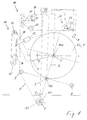
Figur 1- einen Rollenwechsler mit einer verbrauchten Arbeitsrolle und einer neuen Vorratsrolle vor einem Rollenwechsel,
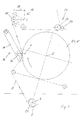
Figur 2- den Rollenwechsler in einem Zustand, in dem eine von der Arbeitsrolle ablaufende Arbeitsbahn an die Vorratsrolle angedrückt ist,
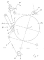
Figur 3- den Rollenwechsler nach einem teilweisen Ausziehen der Arbeitsbahn,
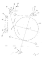
Figur 4- den Rollenwechsler nach Ablösen einer Vorratsbahn von der Vorratsrolle und
Figur 5- den Rollenwechsler nach dem Rollenwechsel.
- FIG. 1
- a roll changer with a used work roll and a new supply roll before a roll change,
- FIG. 2
- the reel changer in a state in which a working web running from the work roll is pressed against the supply roll,
- FIG. 3
- the reel changer after a partial removal of the working web,
- FIG. 4
- the reel changer after detachment of a supply web of the supply roll and
- FIG. 5
- the reel changer after the roll change.
Die Figuren zeigen einen Rollenwechsler für Rollenrotationsdruckmaschinen, der zur
Aufnahme von zwei Papierrollen R1 und R2 eingerichtet ist. Er weist einen ersten
Rollenarm 1 auf, der die Rolle R1 um eine Drehachse 4 drehbar lagert. Die Rolle R1
bildet eine Arbeitsrolle, von der eine in die Druckmaschine eingezogene Arbeitsbahn A
abwickelt. Die andere Rolle R2 ist an einem zweiten Rollenarm 2 um eine von diesem
Rollenarm 2 gebildete Drehachse 5 ebenfalls drehbar gelagert. Die zweite Rolle R2 ist
eine Vorratsrolle einer Vorratsbahn V, welche die nahezu verbrauchte Arbeitsrolle R1
ersetzen soll. Ein Motor M1 bildet einen Drehantrieb für die Arbeitsrolle R1, der im
Betrieb der Maschine die Arbeitsrolle R1 um die Drehachse 4 drehantreibt. Ein
ebensolcher Motor M2 bildet einen Drehantrieb für die Vorratsrolle R2, um die
Vorratsrolle R2 um deren Drehachse 5 drehanzutreiben.The figures show a roll changer for web-fed rotary printing presses, which
Recording of two paper rolls R1 and R2 is set up. He has a
Die beiden Rollenarme 1 und 2 bilden fluchtende Schwenkarme um eine gemeinsame
Schwenkachse 3. Ein weiterer Motor M3 bildet einen Schwenkantrieb zum Schwenken
der Rollenarme 1 und 2 um die Schwenkachse 3. Durch die Schwenkbewegung gegen
den Uhrzeigersinn kann der Rollenarm 2 in die für den Rollenarm 1 in den Figuren
dargestellte Schwenkposition geschwenkt werden. Entsprechend wird bei solch einer
Schwenkbewegung der Rollenarm 1 in die in den Figuren für den Rollenarm 2 gezeigte
Schwenkposition geschwenkt. Des Weiteren sind zwei Umlenkwalzen 9 an
Schwenkarmen um die Schwenkachse 3 schwenkbar. Die Schwenkarme für die
Umlenkwalzen 9 sind drehsteif mit den Rollenarmen 1 und 2 verbunden und bilden mit
diesen ein Kreuz.The two
Zusätzlich zu der beschriebenen Lagereinrichtung für die Rollen R1 und R2 umfasst der
Rollenwechsler entlang eines für die Arbeitsbahn A gebildeten Bahnwegs eine
Verbindungseinrichtung 10, eine Zugeinrichtung 16 und eine Halteeinrichtung 21. In addition to the described bearing device for the rollers R1 and R2 includes the
Reel changer along a path formed for the working path A a
Die Verbindungseinrichtung 10 ist als Klebeeinrichtung ausgebildet. Sie umfasst als
Fügeelement eine Klebewalze 14, die an einem Schwenkarm 11 der Vorratsrolle R2
gegenüberliegend drehgelagert ist. Der Schwenkarm 11 ist um eine Schwenkachse 12
schwenkbar, die parallel zu der Drehachse 5 der Vorratsrolle R2 weist. Auch die
Drehachse der Klebewalze 14 weist parallel zu der Drehachse 5. Die Klebewalze 14 ist,
wie in Figur 1 angedeutet, mittels der Schwenkbewegung um die Schwenkachse 12 an
die Vorratsrolle R2 andrückbar. Die Schwenkbewegung zu der Vorratsrolle R2 hin und
von der Vorratsrolle R2 weg wird mittels eines Schwenkantriebs 13 bewirkt, der von
einer Kolben-Fluidzylinder-Anordnung gebildet wird. Die Arbeitsbahn A wird in der in
den Figuren dargestellten Position der Arbeitsrolle R1 zwischen der Vorratsrolle R2 und
der Klebewalze 14 hindurchgeführt.The connecting
Im Bahnweg der Arbeitsbahn A unmittelbar hinter der Verbindungseinrichtung 10 ist die
Zugeinrichtung 16 angeordnet. Die Zugeinrichtung 16 umfasst einen Zylinderkörper 17,
der an einem Schwenkarm um eine Schwenkachse 18 schwenkbar gelagert ist. Der
Zylinderkörper 17 ist um seine Längsachse frei drehbar gelagert und wird im
Ausführungsbeispiel von einem bahnbreiten Walzenkörper gebildet. Die Arbeitsbahn A
umschlingt den Zylinderkörper 17 mit einem Umschlingungswinkel von mehr als 90°
und wird bahnabwärts von dem Zylinderkörper 17 um eine Umlenkwalze 20 umgelenkt.
Die Arbeitsbahn A ist zwischen der Umlenkwalze 9 der Rollenlagerung und dem
Zylinderkörper 17 frei gespannt, d.h. es befinden sich in diesem Teil des Bahnwegs
keine weiteren Umlenkelemente. Lediglich die Verbindungseinrichtung 10 wirkt zur
Herstellung der Fügeverbindung in diesem Bahnabschnitt auf die Arbeitsbahn A.
Grundsätzlich können jedoch vor und/oder hinter der Verbindungseinrichtung 10 weitere
Umlenkkörper angeordnet sein.In the railway path of the working line A immediately behind the connecting
Der Zylinderkörper 17 bildet vorzugsweise wie im Ausführungsbeispiel eine an sich
bekannte Pendelwalze, die dem Ausgleich von Bahnspannungsschwankungen dient. Der
Zylinderkörper 17 ist dementsprechend gegen eine Elastizitätskraft eines
Rückstellelements, beispielsweise eine Druckfeder oder ein fluidbeaufschlagter Zylinder,
um die Schwenkachse 18 schwenkbar, wobei der Zylinderkörper 17 von der
umschlingenden Arbeitsbahn A aufgrund der Bahnspannung gegen die Kraft des
Rückstellelements bewegt wird. Die Zugeinrichtung 16 ist mit einem Antrieb 19
ausgestattet, der entsprechend der beispielhaft gewählten Pendelwalzenanordnung als
Schwenkantrieb ausgebildet ist. Der Antrieb 19 ist vorzugsweise eine Kolben-Fluidzylinder-Anordnung
und dient dem Schwenken des Zylinderkörpers 17 um die
Schwenkachse 18. In den Figuren sind eine mittlere Normal- oder Sollposition und zwei
beidseits der mittleren Position gelegene Positionen des Zylinderkörpers 17 dargestellt.The
Im Bahnweg der Arbeitsbahn A folgt auf die derart gebildete Spann- und Zugeinrichtung
16 die Halteeinrichtung 21. Die Halteeinrichtung 21 umfasst einen drehangetriebenen
Zylinderkörper 22, der von der Arbeitsbahn A umschlungen wird. Im
Ausführungsbeispiel ist der Zylinderkörper 22, wie dies bevorzugt wird, eine Zugwalze.
Zwischen der Umlenkwalze 20 der Spann- und Zugeinrichtung 16 und der Zugwalze 22
ist die Arbeitsbahn A frei gespannt, d.h. es wirken in diesem Bahnabschnitt keine
weiteren Elemente auf die Arbeitsbahn A. Grundsätzlich können jedoch Umlenkkörper
dazwischen angeordnet sein. Die Halteeinrichtung 21 wird vorzugsweise von einer von
Hause aus vorhandenen Zugeinrichtung gebildet, die zwischen der Spann- und
Zugeinrichtung 16 und dem im Bahnweg nächstgelegenen Druckwerk der Maschine
angeordnet ist. Falls solch ein Einzugswerk mehrere Zugwalzen aufweist, bildet
vorzugsweise die im Bahnweg der Spann- und Zugeinrichtung 16 nächstgelegene
Zugwalze den Zylinderkörper 22. Um sicherzustellen, dass die Arbeitsbahn A im
Bedarfsfall von der Halteeinrichtung 21 so fixiert werden kann, dass sie sich unter dem
Einfluss der bei einem Rollenwechsel wirksamen Zugkräfte nicht bewegt, ist dem
Zylinderkörper 22 gegenüberliegend ein von einem Klemmelement 23 gebildetes
Blockierelement angeordnet, das an den Zylinderkörper 22 an und von dem
Zylinderkörper 22 abgestellt werden kann, beispielsweise im Wege einer
Schwenklagerung des Klemmelements 23. Das Klemmelement 23 wird bei Ausbildung
des Zylinderkörpers 22 als Walze vorzugsweise ebenfalls von einem Walzenkörper
gebildet, der zum Zwecke der Fixierung der Arbeitsbahn A allerdings um seine eigene
Längsachse nicht drehbar ist. In the path of the work A track follows the tensioning and pulling device thus formed
16, the holding
Schließlich umfasst der Rollenwechsler noch einen auf die Oberfläche der Vorratsrolle
R2 gerichteten Sensor 7. Der Sensor 7 dient der Detektion einer Klebestelle 6, an der ein
Bahnanfang der Vorratsbahn V an eine nächste Bahnlage der Vorratsrolle R2 geklebt ist.Finally, the roll changer still includes one on the surface of the supply roll
R2 directed
Einer Steuerungseinrichtung 24 werden die Signale des Sensors 7 zugeleitet. Die
Steuerungseinrichtung 24 dient der Steuerung und vorzugsweise auch Regelung der
Antriebe M1, M2, M3, 13 und 19, eines Drehantriebs für den Zylinderkörper 22 und
eines Antriebs für das An- und Abstellen des Klemmelements 23. Die entsprechenden
Verbindungen mit den genannten Antrieben zur Übermittlung der Stellsignale sind in
strichlierten Linien eingezeichnet. Die Verbindung kann jeweils leitungsgebunden oder
leitungslos, beispielsweise per Funk oder optisch, ausgeführt sein. Mittels der
Steuerungseinrichtung 24 wird der Rollenwechsel zumindest nach einem gegebenenfalls
manuellen Einsetzen der Vorratsrolle R2 und Entnehmen der alten, beispielsweise
verbrauchten Arbeitsrolle R1 automatisch ausgeführt. Dies gilt für einen fliegenden
Rollenwechsel bei laufender Produktion und, nach der Erfindung, auch für einen im
Stillstand des Rollenwechslers auszuführenden Rollenwechsel.A
Ein automatischer Rollenwechsel im Stillstand wird nachfolgend beschrieben. Die zeitliche Ablaufsequenz beim Stillstandswechsel ist in den Figuren 1 bis 5 dargestellt.An automatic roll change at standstill is described below. The Time sequence sequence at standstill change is shown in Figures 1 to 5.
Figur 1 zeigt den Rollenwechsler mit eingezogener Arbeitsbahn A. Die von der
Arbeitsrolle R1 abgewickelte Arbeitsbahn A ist zunächst über die eine der Umlenkwalzen
9 und zwischen der Vorratsrolle R2 und der Verbindungseinrichtung 10 hindurch zu der
Spann- und Zugeinrichtung 16 geführt, umschlingt den Zylinderkörper 17 um etwa 140°,
wird unmittelbar hinter dem Zylinderkörper 17 von der Umlenkwalze 20 zu dem
Zylinderkörper 22 der Halteeinrichtung 21 umgelenkt, umschlingt den Zylinderkörper 22
um vorzugsweise wenigstens 90° und ist von dort schließlich durch den ersten
Druckspalt der Druckmaschine geführt. In dem in Figur 1 dargestellten Zustand des
Rollenwechslers befindet sich die Arbeitsrolle R1 in einer Arbeitsposition und die
Vorratsrolle R2 in einer Füge- bzw. Klebeposition, aus der sie nach dem Kleben
zusammen in eine Arbeitsposition für die jetzige Vorratsrolle und neue Arbeitsrolle R2
weitergeschwenkt werden. Der Schwenkarm 11 mit der Klebewalze 14 befindet sich in
einer Ausgangsposition, in der die Arbeitsbahn A nicht berührt wird, d.h. die
Arbeitsbahn A läuft in dem gezeigten Zustand zwischen der Vorratsrolle R2 und der
Verbindungseinrichtung 10 frei durch. Der Zylinderkörper 17 der Spann- und
Zugeinrichtung 16 wird durch den Antrieb der Arbeitsrolle R1 mittels der Arbeitsbahn
A, d.h. durch deren Bahnspannung, in einer vorderen Position gehalten, in der der
Bahnweg zwischen den einander nächstgelegenen Umlenkwalzen 9 und 20 zu beiden
Seiten des Zylinderkörpers 17 seine geringste Länge aufweist. Die Arbeitsbahn A wird
bereits von der Halteeinrichtung 21 fixiert, indem das Klemmelement 23 mit einer
Presskraft gegen den Zylinderkörper 22 gedrückt ist und die Bahn A in der zwischen
dem Zylinderkörper 22 und dem an seiner Oberfläche vorzugsweise elastisch
nachgiebigen Klemmelement 23 gebildeten Klemmstelle fest eingeklemmt ist.Figure 1 shows the reel changer with retracted work A. The from the
Work roll R1 unwound work path A is initially on the one of the
Die Vorratsrolle R2 nimmt in dem in Figur 1 dargestellten Zustand des Rollenwechslers
bereits eine definierte Drehlage ein. Hierfür wurde zuvor die Vorratsrolle R2 in der
gezeigten Schwenkstellung mittels des Motors M2 gedreht. Bei dieser Drehbewegung
wurde die Klebestelle 6 mit Hilfe des Sensors 7 detektiert und von der
Steuerungseinrichtung 24 bestimmt. Nach der Detektion der Klebestelle 6 und der
Bestimmung der Drehlage wurde die Vorratsrolle R2 mittels des Motors M2 von der
Steuerungseinrichtung 24 gesteuert in die dargestellte Drehwinkelposition mit dem
Drehlagewinkel α gedreht und vorzugsweise in dieser Drehposition festgesetzt. Der diese
Drehposition definierende Drehlagewinkel α ist der in Winkelgrad gemessene Abstand,
den die Klebestelle 6 von der Anpressstelle der Klebewalze 14 hat, wenn die Klebewalze
14 gegen die Vorratsrolle R2 gepresst wird.The supply roll R2 takes in the state shown in Figure 1 of the roll changer
already a defined rotational position. For this purpose, the supply roll R2 in the
shown pivot position rotated by the motor M2. In this rotary motion
the
Figur 2 zeigt den Zustand des Rollenwechslers, nachdem die Klebewalze 14 um die
Schwenkachse 12 geschwenkt und gegen die Vorratsrolle R2 angestellt wurde und nun
gegen deren Oberfläche gepresst ist. Ansonsten nehmen alle weiteren Elemente des
Rollenwechslers einschließlich der Halteeinrichtung 21 noch die gleichen Positionen wie
in dem Zustand der Figur 1 ein. Gegebenenfalls wurde durch das Andrücken die
Arbeitsrolle R1 ein wenig gedreht.FIG. 2 shows the state of the roll changer after the
Figur 3 zeigt die gesamte Anordnung, nachdem die Arbeitsbahn A mittels der
Zugeinrichtung 16 bereits ein Stück weit gegenüber dem in Figur 2 dargestellten Zustand
von der Arbeitsrolle R1 abgezogen worden ist. Um die hierfür erforderliche Zugkraft auf
die Arbeitsbahn A auszuüben, wurde der Zylinderkörper 17 von dem Antrieb 19 um die
Schwenkachse 18 und gegen die Bahnspannung in die in Figur 3 gezeigte, mittlere
Sollposition geschwenkt. Diese Sollposition nimmt der Zylinderkörper 17 im laufenden
Betrieb ebenfalls ein, schwenkt dabei allerdings frei nach Maßgabe des
Zusammenwirkens der Bahnspannung und des Rückstellelements. Während des
Ausziehens der Arbeitsbahn A durch die mittels dem Antrieb 19 erzwungene
Schwenkbewegung des Zylinderkörpers 17 wird die Drehbewegung der Arbeitsrolle R1
mittels dem Motor M1 und/oder einer Bremse 8 derart kontrolliert, dass sich eine
günstige Bahnspannung und Auszugsgeschwindigkeit einstellt. Besonders bevorzugt wird
eine zusätzliche Bremse 8 hierbei nicht benötigt. Es wird vielmehr während des
Ausziehens der Arbeitsbahn A der Motor M1 mit einer definierten Drehzahl angetrieben
oder arbeitet sogar als Bremsgenerator, und es wird der Zylinderkörper 17 von dem
Antrieb 19 mit einer definierten Rückstellkraft beaufschlagt, so dass der Zylinderkörper
17 die mittlere Sollposition einnimmt. Die Ausziehbewegung der Arbeitsbahn A ist in
Figur 3 mit zwei ausgezogenen Pfeilen im Bahnweg angedeutet.Figure 3 shows the entire arrangement, after the working path A by means of
Während der Ausziehbewegung ist die Vorratsrolle R1 aufgrund des mittels der
andrückenden Klebewalze 14 bewirkten Reibschlusses aus ihrer in den Figuren 1 und 2
dargestellten Drehwinkelposition in die in Figur 3 dargestellte Drehposition gedreht
worden, in der die Klebestelle 6 unter der Klebewalze 14 zu liegen kommt. Da die
Klebestelle 6 zuvor bereits "scharf" gemacht worden ist, wird in der gezeigten
Drehwinkelposition die Arbeitsbahn A von der Klebewalze 14 fest gegen den die
Klebestelle 6 aufweisenden Bahnanfang der Vorratsbahn V gedrückt und dadurch der
Bahnanfang der Vorratsbahn V an die Arbeitsbahn A geklebt. Die Bremskraft der
Bremse 8 wird von der Steuerungseinrichtung 24 abgestimmt auf die Schwenkbewegung
des Zylinderkörpers 17 der Zugeinrichtung 16 eingestellt. Die Abstimmung ist derart,
dass die Bremskraft der Bremse 8 so eingestellt ist, dass der Zylinder 17 der
Zugeinrichtung 16 eine Schwenkbewegung mit einer definierten Geschwindigkeit
ausführt bis hin zu einer hinteren Position, die in Figur 4 in einer ausgezogenen Linie
dargestellt ist. Anstatt einer zusätzlichen Bremse 8 kann der Motor M1 als
Bremsgenerator betrieben werden. Insbesondere kann ein Motor für beide
Drehrichtungen den Motor M1 bilden. Auch solch ein Motor mit umkehrbarer
Drehrichtungen kann zusätzlich als Bremsgenerator ausgebildet sein.During the pull-out movement, the supply roll R1 is due to the means of
pressing
Figur 4 zeigt in der Sequenz den Zustand, in dem der Zylinderkörper 17 seine hintere
Position einnimmt und die Arbeitsbahn A deshalb im Rahmen des Stillstands-Rollenwechsels
um die maximale Auszugslänge ausgezogen worden ist. Während des
gesamten Auszugvorgangs, d.h. von dem in Figur 2 bis zu dem in Figur 4 dargestellten
Zustand ist die Klebewalze 14 gegen die Vorratsrolle R2 gepresst. Nach Herstellen der
Verbindung, was in erster Linie in dem in Figur 3 dargestellten Zustand erfolgt, wird
durch das weitere Anpressen der Klebewalze 14 ein sauberes Ablösen des Bahnanfangs
der Vorratsbahn V von der Vorratsrolle R2 bewirkt. In dem in Figur 4 dargestellten
Zustand ist der Bahnanfang der Vorratsbahn V bereits von der Vorratsrolle R2 abgelöst.
Ferner ist nach dem Ablösen des Bahnanfangs auch bereits die Arbeitsbahn A hinter der
Klebestelle 6, d.h. wie im Ausführungsbeispiel noch bevorzugter hinter der Klebewalze
14, mittels des Kappmessers 15 gekappt worden. Figur 4 zeigt die alte Arbeitsbahn A
unmittelbar nach dem Kappen.Figure 4 shows in sequence the state in which the
Nach dem Kappen wird die Bremse 8 gelöst, und es wird die Arbeitsbahn A durch
Rückdrehung der Arbeitsrolle R1 wieder bis zum gekappten Bahnanfang der Arbeitsbahn
A auf die Arbeitsrolle R1 aufgewickelt. Dieser Zustand ist in Figur 5 dargestellt.
Anschließend kann die alte Arbeitsrolle R1 automatisch oder von Hand aus dem
Rollenwechsler genommen werden.After capping the
Nachdem die Verbindung hergestellt und der Bahnanfang der Vorratsbahn von der
Vorratsrolle R2 abgelöst worden ist, wird die Verbindungseinrichtung 10 wieder von der
Vorratsrolle R2 abgestellt. Anschließend wird der Zylinderkörper 17 durch den Antrieb
M1 der Arbeitsrolle R1 aus seiner in Figur 4 dargestellten hinteren Position zurück in die
mittlere Position (Sollposition) bewegt, die der Zylinderkörper 17 auch im späteren
Betrieb der Maschine einnimmt bzw. um die er im Falle von Bahnschwankungen
oszilliert. Die Arbeitsbahn A ist währenddessen weiterhin von der Halte- und
Zugeinrichtung 21 fixiert. Während der Rückbewegung des Zylinderkörpers 10 in die
Mittelposition wird die Vorratsrolle R2, von der im Weiteren die Arbeitsbahn abwickelt,
zurückgedreht, um die Bahnspannung konstant oder zumindest im Wesentlichen konstant
zu halten. Die Rückdrehbewegung ist durch den eingezeichneten Drehpfeil angedeutet.
Der Rollenwechsel ist in diesem, in Figur 5 dargestellten Zustand beendet.After the connection has been made and the web start of the supply line of the
Supply roll R2 has been replaced, the connecting
Falls der Antrieb 19 ein Pneumatikantrieb ist, kann er auch das Rückstellelement für den
elastischen Ausgleich von Bahnschwankungen bilden. Weist er jedoch keine Elastizität
auf, weil er beispielsweise von einem Hydraulikantrieb oder Elektroantrieb gebildet
wird, so ist solch ein Antrieb 19 für die Zwecke des Bahnspannungsausgleichs im
laufenden Maschinenbetrieb ausgekuppelt.If the
Zur Aufnahme der Produktion mit der von der Vorratsbahn gebildeten neuen
Arbeitsbahn muss lediglich noch die Fixierung zwischen dem Zylinderkörper 22 und dem
Klemmelement 23 durch Abstellen des Klemmelements 23 gelöst werden.To start production with the new one formed by the supply track
Work path has only the fixation between the
- 11
- Lagerung, erster RollenarmStorage, first roller arm
- 22
- Lagerung, zweiter RollenarmStorage, second roller arm
- 33
- Schwenkachseswivel axis
- 44
- Drehachseaxis of rotation
- 55
- Drehachseaxis of rotation
- 66
- Klebestelle splice
- 77
- Sensorsensor
- 88th
- Bremsebrake
- 99
- Umlenkwalzedeflecting
- 1010
- Verbindungseinrichtung, KlebeeinrichtungConnecting device, adhesive device
- 1111
- Schwenkarmswivel arm
- 1212
- Schwenkachseswivel axis
- 1313
- SchwenkantriebRotary actuator
- 1414
- Anpresselement, KlebewalzePressing element, adhesive roller
- 1515
- KappmesserCutting knife
- 1616
- Zugeinrichtungdrawbar
- 1717
- Zylinderkörper, PendelwalzeCylinder body, pendulum roller
- 1818
- Schwenkachseswivel axis
- 1919
- Antriebdrive
- 2020
- Umlenkwalzedeflecting
- 2121
- Halteeinrichtungholder
- 2222
- Zugelement, ZugwalzeTension element, tension roller
- 2323
- Klemmelement, BlockierelementClamping element, blocking element
- 2424
- Steuerungseinrichtungcontrol device
- AA
- Arbeitsbahnworking web
- VV
- Vorratsbahnsupply web
- M1M1
- Rollenantriebroller drive
- M2M2
- Rollenantriebroller drive
- M3M3
- SchwenkantriebRotary actuator
- R1R1
- Arbeitsrollework role
- R2R2
- Vorratsrollesupply roll
- αα
- DrehlagewinkelRotational position angle
Claims (13)
Applications Claiming Priority (2)
| Application Number | Priority Date | Filing Date | Title |
|---|---|---|---|
| DE10146631 | 2001-09-21 | ||
| DE10146631A DE10146631B4 (en) | 2001-09-21 | 2001-09-21 | Roll changer and method for automatic roll change at standstill |
Publications (4)
| Publication Number | Publication Date |
|---|---|
| EP1295830A2 true EP1295830A2 (en) | 2003-03-26 |
| EP1295830A3 EP1295830A3 (en) | 2005-01-26 |
| EP1295830B1 EP1295830B1 (en) | 2007-03-21 |
| EP1295830B2 EP1295830B2 (en) | 2009-06-17 |
Family
ID=7699843
Family Applications (1)
| Application Number | Title | Priority Date | Filing Date |
|---|---|---|---|
| EP02405806A Expired - Lifetime EP1295830B2 (en) | 2001-09-21 | 2002-09-17 | Roll changer and method for the automatic change of rolls during stop |
Country Status (5)
| Country | Link |
|---|---|
| US (1) | US6729573B2 (en) |
| EP (1) | EP1295830B2 (en) |
| AT (1) | ATE357395T1 (en) |
| DE (2) | DE10146631B4 (en) |
| ES (1) | ES2284804T5 (en) |
Cited By (2)
| Publication number | Priority date | Publication date | Assignee | Title |
|---|---|---|---|---|
| EP1870359A2 (en) * | 2006-06-21 | 2007-12-26 | Focus S.r.l. | Apparatus for feeding a material in the form of a continuous web to one or more operating machines |
| DE102008028165A1 (en) * | 2008-06-12 | 2009-12-17 | Manroland Ag | Reel changer for a web-fed printing press and method of operating the same |
Families Citing this family (6)
| Publication number | Priority date | Publication date | Assignee | Title |
|---|---|---|---|---|
| JP3539565B2 (en) * | 2002-02-05 | 2004-07-07 | 株式会社東京機械製作所 | Web press for web press |
| ITFI20040016A1 (en) * | 2004-01-21 | 2004-04-21 | Perini Fabio Spa | UNWINDING DEVICE FOR TAPES OF TAPE MATERIAL AND RELATED METHOD |
| DE102008000242B3 (en) * | 2008-02-06 | 2009-01-22 | Koenig & Bauer Aktiengesellschaft | Method e.g. for halt roll exchange in roll exchanger, involves deviating new material in connection position and moving coupling device to new material |
| DE102011007457A1 (en) * | 2011-04-15 | 2012-10-18 | Robert Bosch Gmbh | Method and device for connecting two film webs |
| DE102011084935A1 (en) | 2011-10-21 | 2013-04-25 | Koenig & Bauer Aktiengesellschaft | Method for drawing at least one material web into a processing device |
| EP3392029B1 (en) | 2017-04-21 | 2022-01-05 | Held Technologie GmbH | Feeding device for a double belt press, double belt press system and method of operation |
Citations (8)
| Publication number | Priority date | Publication date | Assignee | Title |
|---|---|---|---|---|
| DE1256501B (en) * | 1962-11-13 | 1967-12-14 | Gevaert Photo Prod Nv | Method and device for continuous butt-to-butt joining of webs |
| US4453152A (en) † | 1983-01-10 | 1984-06-05 | The Singer Company | Sewing machine control |
| US4705226A (en) * | 1986-01-17 | 1987-11-10 | Valmet-Strecker Gmbh | Device for automatically splicing a web of material in a web feeding apparatus |
| US4892263A (en) * | 1987-07-17 | 1990-01-09 | J. M. Voith Gmbh | Unwinding apparatus for a paper or board web |
| US5064488A (en) * | 1990-03-27 | 1991-11-12 | Trine Manufacturing Company, Inc. | Apparatus and method for splicing film |
| US5253819A (en) † | 1991-09-04 | 1993-10-19 | Butler Automatic, Inc. | Speed match splicing method and apparatus |
| US5514237A (en) * | 1993-10-05 | 1996-05-07 | The Procter & Gamble Company | Heat splicing of thermoplastic film |
| EP1223134A2 (en) † | 2000-12-07 | 2002-07-17 | Heidelberger Druckmaschinen Aktiengesellschaft | Flying roll changer in a rotary printing machine |
Family Cites Families (9)
| Publication number | Priority date | Publication date | Assignee | Title |
|---|---|---|---|---|
| US3279716A (en) * | 1963-09-09 | 1966-10-18 | William F Huck | Continuous web winding rollstand |
| US3326486A (en) * | 1965-09-02 | 1967-06-20 | Huck William F | Automatic controls for splicing rollstand |
| US3391877A (en) * | 1966-09-28 | 1968-07-09 | Hurletron Inc | Automatic preprint paster apparatus and method for using same |
| JPS5931244A (en) * | 1982-08-09 | 1984-02-20 | Dainippon Printing Co Ltd | Paper feeder with automatic paper connection |
| DE3440107A1 (en) * | 1984-11-02 | 1986-05-22 | Jagenberg AG, 4000 Düsseldorf | Method and device for connecting a first web of material running to a processing machine to the start of a wound-up second web of material |
| DE3931852A1 (en) * | 1989-09-23 | 1991-04-04 | Erhardt & Leimer Gmbh | ROLE CHANGER |
| DE4000745A1 (en) * | 1990-01-12 | 1991-07-18 | Roland Man Druckmasch | REEL CHANGE DEVICE FOR A PRINTING MACHINE |
| JPH0671954B2 (en) * | 1990-11-29 | 1994-09-14 | 株式会社東京機械製作所 | Paper splicing device |
| JP2943106B1 (en) * | 1998-05-18 | 1999-08-30 | 株式会社東京機械製作所 | Vibration control method for traveling web, vibration control device, and paper splicing assist device |
-
2001
- 2001-09-21 DE DE10146631A patent/DE10146631B4/en not_active Expired - Fee Related
-
2002
- 2002-09-17 DE DE50209753T patent/DE50209753D1/en not_active Expired - Lifetime
- 2002-09-17 AT AT02405806T patent/ATE357395T1/en not_active IP Right Cessation
- 2002-09-17 ES ES02405806T patent/ES2284804T5/en not_active Expired - Lifetime
- 2002-09-17 EP EP02405806A patent/EP1295830B2/en not_active Expired - Lifetime
- 2002-09-19 US US10/247,133 patent/US6729573B2/en not_active Expired - Fee Related
Patent Citations (8)
| Publication number | Priority date | Publication date | Assignee | Title |
|---|---|---|---|---|
| DE1256501B (en) * | 1962-11-13 | 1967-12-14 | Gevaert Photo Prod Nv | Method and device for continuous butt-to-butt joining of webs |
| US4453152A (en) † | 1983-01-10 | 1984-06-05 | The Singer Company | Sewing machine control |
| US4705226A (en) * | 1986-01-17 | 1987-11-10 | Valmet-Strecker Gmbh | Device for automatically splicing a web of material in a web feeding apparatus |
| US4892263A (en) * | 1987-07-17 | 1990-01-09 | J. M. Voith Gmbh | Unwinding apparatus for a paper or board web |
| US5064488A (en) * | 1990-03-27 | 1991-11-12 | Trine Manufacturing Company, Inc. | Apparatus and method for splicing film |
| US5253819A (en) † | 1991-09-04 | 1993-10-19 | Butler Automatic, Inc. | Speed match splicing method and apparatus |
| US5514237A (en) * | 1993-10-05 | 1996-05-07 | The Procter & Gamble Company | Heat splicing of thermoplastic film |
| EP1223134A2 (en) † | 2000-12-07 | 2002-07-17 | Heidelberger Druckmaschinen Aktiengesellschaft | Flying roll changer in a rotary printing machine |
Cited By (4)
| Publication number | Priority date | Publication date | Assignee | Title |
|---|---|---|---|---|
| EP1870359A2 (en) * | 2006-06-21 | 2007-12-26 | Focus S.r.l. | Apparatus for feeding a material in the form of a continuous web to one or more operating machines |
| EP1870359A3 (en) * | 2006-06-21 | 2011-04-13 | Focus S.r.l. | Apparatus for feeding a material in the form of a continuous web to one or more operating machines |
| DE102008028165A1 (en) * | 2008-06-12 | 2009-12-17 | Manroland Ag | Reel changer for a web-fed printing press and method of operating the same |
| EP2133297B1 (en) | 2008-06-12 | 2016-04-13 | manroland web systems GmbH | Roller changer for a roller printing press and method for operating same |
Also Published As
| Publication number | Publication date |
|---|---|
| EP1295830B1 (en) | 2007-03-21 |
| DE10146631A1 (en) | 2003-04-10 |
| US6729573B2 (en) | 2004-05-04 |
| EP1295830B2 (en) | 2009-06-17 |
| DE50209753D1 (en) | 2007-05-03 |
| ES2284804T3 (en) | 2007-11-16 |
| EP1295830A3 (en) | 2005-01-26 |
| DE10146631B4 (en) | 2004-03-04 |
| ATE357395T1 (en) | 2007-04-15 |
| US20030057315A1 (en) | 2003-03-27 |
| ES2284804T5 (en) | 2009-10-15 |
Similar Documents
| Publication | Publication Date | Title |
|---|---|---|
| EP0711724B1 (en) | Apparatus for separating perforated tubular web sections | |
| DE3031040A1 (en) | DEVICE FOR AUTOMATICALLY CONNECTING COILS OR COILS, IN PARTICULAR PAPER COILS | |
| DE3723601C2 (en) | ||
| DE4141242A1 (en) | METHOD AND DEVICE FOR PREPARING THE BEGINNING OF A REPLACEMENT REEL FOR THE FLYING REEL CHANGE | |
| DE19608842B4 (en) | Device and method for the web feed | |
| EP0578956A1 (en) | Device for splicing two webs | |
| EP1295830B2 (en) | Roll changer and method for the automatic change of rolls during stop | |
| DE102006042217B4 (en) | A method performed in a roll changer for a web-fed printing machine for joining a first material web to a second material web | |
| DE2344870C3 (en) | Device for end-to-end connection of two tracks | |
| DE102008000242B3 (en) | Method e.g. for halt roll exchange in roll exchanger, involves deviating new material in connection position and moving coupling device to new material | |
| DE69914868T2 (en) | Automatic splicer for unwinder | |
| DE3914776A1 (en) | METHOD AND DEVICE FOR WINDING AND CROSS-CUTTING A RUNNING GOODS | |
| DE19704332B4 (en) | Apparatus for processing at least two webs of paper or plastic film | |
| DE3440107C2 (en) | ||
| EP0100462A2 (en) | Web winding device | |
| WO2009135805A1 (en) | Device and method for winding strip-shaped material and strip processing machine | |
| DE19754106A1 (en) | Device and method for pulling in a printing material web | |
| EP0406581A1 (en) | Arrangement for chopping of a web on a reversing winder | |
| EP0221524B1 (en) | Arrangement for drawing webs | |
| DE10219611B4 (en) | reelstands | |
| DE10063000C2 (en) | Device for connecting two rolls of material | |
| DE10058437B4 (en) | Devices for connecting two webs of material | |
| DE102013209559B4 (en) | Device for winding a material web into a roll and method for using this device | |
| DE3312038A1 (en) | Device for drawing in webs of material in rotary printing machines | |
| DE102008022702B4 (en) | Method and apparatus for unwinding and storing sheet material |
Legal Events
| Date | Code | Title | Description |
|---|---|---|---|
| PUAI | Public reference made under article 153(3) epc to a published international application that has entered the european phase |
Free format text: ORIGINAL CODE: 0009012 |
|
| AK | Designated contracting states |
Kind code of ref document: A2 Designated state(s): AT BE BG CH CY CZ DE DK EE ES FI FR GB GR IE IT LI LU MC NL PT SE SK TR |
|
| AX | Request for extension of the european patent |
Extension state: AL LT LV MK RO SI |
|
| PUAL | Search report despatched |
Free format text: ORIGINAL CODE: 0009013 |
|
| AK | Designated contracting states |
Kind code of ref document: A3 Designated state(s): AT BE BG CH CY CZ DE DK EE ES FI FR GB GR IE IT LI LU MC NL PT SE SK TR |
|
| AX | Request for extension of the european patent |
Extension state: AL LT LV MK RO SI |
|
| 17P | Request for examination filed |
Effective date: 20050726 |
|
| AKX | Designation fees paid |
Designated state(s): AT BE BG CH CY CZ DE DK EE ES FI FR GB GR IE IT LI LU MC NL PT SE SK TR |
|
| GRAP | Despatch of communication of intention to grant a patent |
Free format text: ORIGINAL CODE: EPIDOSNIGR1 |
|
| GRAS | Grant fee paid |
Free format text: ORIGINAL CODE: EPIDOSNIGR3 |
|
| GRAA | (expected) grant |
Free format text: ORIGINAL CODE: 0009210 |
|
| AK | Designated contracting states |
Kind code of ref document: B1 Designated state(s): AT BE BG CH CY CZ DE DK EE ES FI FR GB GR IE IT LI LU MC NL PT SE SK TR |
|
| PG25 | Lapsed in a contracting state [announced via postgrant information from national office to epo] |
Ref country code: IE Free format text: LAPSE BECAUSE OF FAILURE TO SUBMIT A TRANSLATION OF THE DESCRIPTION OR TO PAY THE FEE WITHIN THE PRESCRIBED TIME-LIMIT Effective date: 20070321 |
|
| REG | Reference to a national code |
Ref country code: GB Ref legal event code: FG4D Free format text: NOT ENGLISH |
|
| REG | Reference to a national code |
Ref country code: CH Ref legal event code: EP |
|
| REF | Corresponds to: |
Ref document number: 50209753 Country of ref document: DE Date of ref document: 20070503 Kind code of ref document: P |
|
| REG | Reference to a national code |
Ref country code: IE Ref legal event code: FG4D Free format text: LANGUAGE OF EP DOCUMENT: GERMAN |
|
| GBT | Gb: translation of ep patent filed (gb section 77(6)(a)/1977) |
Effective date: 20070531 |
|
| REG | Reference to a national code |
Ref country code: SE Ref legal event code: TRGR |
|
| ET | Fr: translation filed | ||
| PG25 | Lapsed in a contracting state [announced via postgrant information from national office to epo] |
Ref country code: PT Free format text: LAPSE BECAUSE OF FAILURE TO SUBMIT A TRANSLATION OF THE DESCRIPTION OR TO PAY THE FEE WITHIN THE PRESCRIBED TIME-LIMIT Effective date: 20070821 |
|
| REG | Reference to a national code |
Ref country code: IE Ref legal event code: FD4D |
|
| REG | Reference to a national code |
Ref country code: ES Ref legal event code: FG2A Ref document number: 2284804 Country of ref document: ES Kind code of ref document: T3 |
|
| PG25 | Lapsed in a contracting state [announced via postgrant information from national office to epo] |
Ref country code: SK Free format text: LAPSE BECAUSE OF FAILURE TO SUBMIT A TRANSLATION OF THE DESCRIPTION OR TO PAY THE FEE WITHIN THE PRESCRIBED TIME-LIMIT Effective date: 20070321 |
|
| PG25 | Lapsed in a contracting state [announced via postgrant information from national office to epo] |
Ref country code: CZ Free format text: LAPSE BECAUSE OF FAILURE TO SUBMIT A TRANSLATION OF THE DESCRIPTION OR TO PAY THE FEE WITHIN THE PRESCRIBED TIME-LIMIT Effective date: 20070321 |
|
| PLBI | Opposition filed |
Free format text: ORIGINAL CODE: 0009260 |
|
| PLAX | Notice of opposition and request to file observation + time limit sent |
Free format text: ORIGINAL CODE: EPIDOSNOBS2 |
|
| PG25 | Lapsed in a contracting state [announced via postgrant information from national office to epo] |
Ref country code: DK Free format text: LAPSE BECAUSE OF FAILURE TO SUBMIT A TRANSLATION OF THE DESCRIPTION OR TO PAY THE FEE WITHIN THE PRESCRIBED TIME-LIMIT Effective date: 20070321 |
|
| 26 | Opposition filed |
Opponent name: MAN ROLAND DRUCKMASCHINEN AG Effective date: 20071220 |
|
| BERE | Be: lapsed |
Owner name: MASCHINENFABRIK WIFAG Effective date: 20070930 |
|
| NLR1 | Nl: opposition has been filed with the epo |
Opponent name: MAN ROLAND DRUCKMASCHINEN AG |
|
| PG25 | Lapsed in a contracting state [announced via postgrant information from national office to epo] |
Ref country code: GR Free format text: LAPSE BECAUSE OF FAILURE TO SUBMIT A TRANSLATION OF THE DESCRIPTION OR TO PAY THE FEE WITHIN THE PRESCRIBED TIME-LIMIT Effective date: 20070622 Ref country code: MC Free format text: LAPSE BECAUSE OF NON-PAYMENT OF DUE FEES Effective date: 20070930 |
|
| PLBB | Reply of patent proprietor to notice(s) of opposition received |
Free format text: ORIGINAL CODE: EPIDOSNOBS3 |
|
| PLAB | Opposition data, opponent's data or that of the opponent's representative modified |
Free format text: ORIGINAL CODE: 0009299OPPO |
|
| PG25 | Lapsed in a contracting state [announced via postgrant information from national office to epo] |
Ref country code: BE Free format text: LAPSE BECAUSE OF NON-PAYMENT OF DUE FEES Effective date: 20070930 |
|
| PLAB | Opposition data, opponent's data or that of the opponent's representative modified |
Free format text: ORIGINAL CODE: 0009299OPPO |
|
| R26 | Opposition filed (corrected) |
Opponent name: MANROLAND AG Effective date: 20071220 |
|
| PG25 | Lapsed in a contracting state [announced via postgrant information from national office to epo] |
Ref country code: AT Free format text: LAPSE BECAUSE OF NON-PAYMENT OF DUE FEES Effective date: 20070917 |
|
| NLR1 | Nl: opposition has been filed with the epo |
Opponent name: MANROLAND AG |
|
| PG25 | Lapsed in a contracting state [announced via postgrant information from national office to epo] |
Ref country code: EE Free format text: LAPSE BECAUSE OF FAILURE TO SUBMIT A TRANSLATION OF THE DESCRIPTION OR TO PAY THE FEE WITHIN THE PRESCRIBED TIME-LIMIT Effective date: 20070321 |
|
| PGFP | Annual fee paid to national office [announced via postgrant information from national office to epo] |
Ref country code: SE Payment date: 20080923 Year of fee payment: 7 |
|
| RAP2 | Party data changed (patent owner data changed or rights of a patent transferred) |
Owner name: WIFAG MASCHINENFABRIK AG |
|
| PUAH | Patent maintained in amended form |
Free format text: ORIGINAL CODE: 0009272 |
|
| STAA | Information on the status of an ep patent application or granted ep patent |
Free format text: STATUS: PATENT MAINTAINED AS AMENDED |
|
| REG | Reference to a national code |
Ref country code: CH Ref legal event code: PFA Owner name: WIFAG MASCHINENFABRIK AG Free format text: MASCHINENFABRIK WIFAG#WYLERRINGSTRASSE 39 POSTFACH#3001 BERN (CH) -TRANSFER TO- WIFAG MASCHINENFABRIK AG#WYLERRINGSTRASSE 39 POSTFACH 8865#3001 BERN (CH) |
|
| NLT2 | Nl: modifications (of names), taken from the european patent patent bulletin |
Owner name: WIFAG MASCHINENFABRIK AG Effective date: 20090408 |
|
| 27A | Patent maintained in amended form |
Effective date: 20090617 |
|
| AK | Designated contracting states |
Kind code of ref document: B2 Designated state(s): AT BE BG CH CY CZ DE DK EE ES FI FR GB GR IE IT LI LU MC NL PT SE SK TR |
|
| REG | Reference to a national code |
Ref country code: CH Ref legal event code: AEN Free format text: AUFRECHTERHALTUNG DES PATENTES IN GEAENDERTER FORM |
|
| PG25 | Lapsed in a contracting state [announced via postgrant information from national office to epo] |
Ref country code: CY Free format text: LAPSE BECAUSE OF FAILURE TO SUBMIT A TRANSLATION OF THE DESCRIPTION OR TO PAY THE FEE WITHIN THE PRESCRIBED TIME-LIMIT Effective date: 20070321 |
|
| NLR2 | Nl: decision of opposition |
Effective date: 20090617 |
|
| PG25 | Lapsed in a contracting state [announced via postgrant information from national office to epo] |
Ref country code: LU Free format text: LAPSE BECAUSE OF NON-PAYMENT OF DUE FEES Effective date: 20070917 Ref country code: BG Free format text: LAPSE BECAUSE OF FAILURE TO SUBMIT A TRANSLATION OF THE DESCRIPTION OR TO PAY THE FEE WITHIN THE PRESCRIBED TIME-LIMIT Effective date: 20070621 |
|
| PG25 | Lapsed in a contracting state [announced via postgrant information from national office to epo] |
Ref country code: TR Free format text: LAPSE BECAUSE OF FAILURE TO SUBMIT A TRANSLATION OF THE DESCRIPTION OR TO PAY THE FEE WITHIN THE PRESCRIBED TIME-LIMIT Effective date: 20070321 |
|
| NLR3 | Nl: receipt of modified translations in the netherlands language after an opposition procedure | ||
| REG | Reference to a national code |
Ref country code: ES Ref legal event code: DC2A Date of ref document: 20090728 Kind code of ref document: T5 |
|
| PGFP | Annual fee paid to national office [announced via postgrant information from national office to epo] |
Ref country code: ES Payment date: 20090928 Year of fee payment: 8 |
|
| PGFP | Annual fee paid to national office [announced via postgrant information from national office to epo] |
Ref country code: FI Payment date: 20090923 Year of fee payment: 8 Ref country code: GB Payment date: 20090922 Year of fee payment: 8 Ref country code: NL Payment date: 20090921 Year of fee payment: 8 |
|
| PGFP | Annual fee paid to national office [announced via postgrant information from national office to epo] |
Ref country code: CH Payment date: 20091221 Year of fee payment: 8 |
|
| PGFP | Annual fee paid to national office [announced via postgrant information from national office to epo] |
Ref country code: IT Payment date: 20090925 Year of fee payment: 8 |
|
| REG | Reference to a national code |
Ref country code: NL Ref legal event code: V1 Effective date: 20110401 |
|
| REG | Reference to a national code |
Ref country code: CH Ref legal event code: PL |
|
| GBPC | Gb: european patent ceased through non-payment of renewal fee |
Effective date: 20100917 |
|
| PG25 | Lapsed in a contracting state [announced via postgrant information from national office to epo] |
Ref country code: IT Free format text: LAPSE BECAUSE OF NON-PAYMENT OF DUE FEES Effective date: 20100917 Ref country code: FI Free format text: LAPSE BECAUSE OF NON-PAYMENT OF DUE FEES Effective date: 20100917 |
|
| REG | Reference to a national code |
Ref country code: FR Ref legal event code: ST Effective date: 20110531 |
|
| PG25 | Lapsed in a contracting state [announced via postgrant information from national office to epo] |
Ref country code: CH Free format text: LAPSE BECAUSE OF NON-PAYMENT OF DUE FEES Effective date: 20100930 Ref country code: LI Free format text: LAPSE BECAUSE OF NON-PAYMENT OF DUE FEES Effective date: 20100930 Ref country code: FR Free format text: LAPSE BECAUSE OF NON-PAYMENT OF DUE FEES Effective date: 20100930 |
|
| PG25 | Lapsed in a contracting state [announced via postgrant information from national office to epo] |
Ref country code: NL Free format text: LAPSE BECAUSE OF NON-PAYMENT OF DUE FEES Effective date: 20110401 Ref country code: GB Free format text: LAPSE BECAUSE OF NON-PAYMENT OF DUE FEES Effective date: 20100917 |
|
| PGFP | Annual fee paid to national office [announced via postgrant information from national office to epo] |
Ref country code: FR Payment date: 20091005 Year of fee payment: 8 |
|
| REG | Reference to a national code |
Ref country code: ES Ref legal event code: FD2A Effective date: 20111019 |
|
| PG25 | Lapsed in a contracting state [announced via postgrant information from national office to epo] |
Ref country code: ES Free format text: LAPSE BECAUSE OF NON-PAYMENT OF DUE FEES Effective date: 20100918 |
|
| PG25 | Lapsed in a contracting state [announced via postgrant information from national office to epo] |
Ref country code: SE Free format text: LAPSE BECAUSE OF NON-PAYMENT OF DUE FEES Effective date: 20090918 |
|
| PGFP | Annual fee paid to national office [announced via postgrant information from national office to epo] |
Ref country code: DE Payment date: 20190923 Year of fee payment: 18 |
|
| REG | Reference to a national code |
Ref country code: DE Ref legal event code: R119 Ref document number: 50209753 Country of ref document: DE |
|
| PG25 | Lapsed in a contracting state [announced via postgrant information from national office to epo] |
Ref country code: DE Free format text: LAPSE BECAUSE OF NON-PAYMENT OF DUE FEES Effective date: 20210401 |