EP1295042B1 - Hubvorrichtung - Google Patents
Hubvorrichtung Download PDFInfo
- Publication number
- EP1295042B1 EP1295042B1 EP01951615A EP01951615A EP1295042B1 EP 1295042 B1 EP1295042 B1 EP 1295042B1 EP 01951615 A EP01951615 A EP 01951615A EP 01951615 A EP01951615 A EP 01951615A EP 1295042 B1 EP1295042 B1 EP 1295042B1
- Authority
- EP
- European Patent Office
- Prior art keywords
- piston
- cylinder
- valve
- pressure
- unit
- Prior art date
- Legal status (The legal status is an assumption and is not a legal conclusion. Google has not performed a legal analysis and makes no representation as to the accuracy of the status listed.)
- Expired - Lifetime
Links
- 239000012530 fluid Substances 0.000 claims description 29
- 230000001105 regulatory effect Effects 0.000 claims 2
- 230000036316 preload Effects 0.000 claims 1
- 230000001360 synchronised effect Effects 0.000 description 12
- 239000003921 oil Substances 0.000 description 7
- 238000007789 sealing Methods 0.000 description 7
- 230000009969 flowable effect Effects 0.000 description 4
- 238000006243 chemical reaction Methods 0.000 description 3
- 230000007423 decrease Effects 0.000 description 3
- 230000006835 compression Effects 0.000 description 2
- 238000007906 compression Methods 0.000 description 2
- 238000006073 displacement reaction Methods 0.000 description 2
- 230000003247 decreasing effect Effects 0.000 description 1
- 239000010720 hydraulic oil Substances 0.000 description 1
- 238000010992 reflux Methods 0.000 description 1
- 230000002441 reversible effect Effects 0.000 description 1
- 230000000630 rising effect Effects 0.000 description 1
Images


Classifications
-
- F—MECHANICAL ENGINEERING; LIGHTING; HEATING; WEAPONS; BLASTING
- F15—FLUID-PRESSURE ACTUATORS; HYDRAULICS OR PNEUMATICS IN GENERAL
- F15B—SYSTEMS ACTING BY MEANS OF FLUIDS IN GENERAL; FLUID-PRESSURE ACTUATORS, e.g. SERVOMOTORS; DETAILS OF FLUID-PRESSURE SYSTEMS, NOT OTHERWISE PROVIDED FOR
- F15B15/00—Fluid-actuated devices for displacing a member from one position to another; Gearing associated therewith
- F15B15/08—Characterised by the construction of the motor unit
- F15B15/14—Characterised by the construction of the motor unit of the straight-cylinder type
- F15B15/1423—Component parts; Constructional details
- F15B15/1447—Pistons; Piston to piston rod assemblies
-
- F—MECHANICAL ENGINEERING; LIGHTING; HEATING; WEAPONS; BLASTING
- F15—FLUID-PRESSURE ACTUATORS; HYDRAULICS OR PNEUMATICS IN GENERAL
- F15B—SYSTEMS ACTING BY MEANS OF FLUIDS IN GENERAL; FLUID-PRESSURE ACTUATORS, e.g. SERVOMOTORS; DETAILS OF FLUID-PRESSURE SYSTEMS, NOT OTHERWISE PROVIDED FOR
- F15B15/00—Fluid-actuated devices for displacing a member from one position to another; Gearing associated therewith
- F15B15/08—Characterised by the construction of the motor unit
- F15B15/14—Characterised by the construction of the motor unit of the straight-cylinder type
- F15B15/149—Fluid interconnections, e.g. fluid connectors, passages
Definitions
- the present invention relates to a lifting device, and in particular on a single or multi-stage Stroke or synchronous stroke device that a pull-out lock include.
- hydraulic cylinders are in shape from single or double acting single or multi-stage Cylinders or synchronous cylinders known. Such cylinders are for example in DE-GM 1976924, in JP 10141323 A or in US-A-1,812,577.
- a first problem occurs with applications where the cylinders serve the loading area, for example a truck.
- the loading area is overturned so much or still load on the folded sidewall lies over which the load should slide, so that the cylinder suddenly suddenly creating a negative pressure is pulled out as far as it will go.
- Another disadvantage is that when using known telescopic cylinders the entire hydraulic system was subjected to strong vibrations which occur particularly when there is no load rests on the telescopic cylinders.
- Another related Problem is that due to the vibrations precise control of the cylinder is not possible, in particular, it is extremely complex, if not even impossible to find a predetermined position between a maximum extended position and a retracted position to reach the cylinder.
- the present Invention the object of an improved lifting device to create what an unwanted pull out of the cylinder as well as vibrations thereof.
- the present invention provides a lifting device with a cylinder with a cavity; a piston member disposed in the cavity of the cylinder, the piston member including a piston portion and a rod portion, the piston portion dividing the cavity of the cylinder into a piston crown space and a piston annulus; and a valve unit with a valve piston, which is assigned to the piston element and is closed up to a predetermined pressure in the piston crown space in order to separate the piston crown space from the piston ring space and through which pressure can flow above this pressure; wherein the valve unit is arranged such that a pressure in the piston annulus does not act on the valve unit in the closing directions of the valve piston and wherein a fluid contained in the piston annulus flows from the piston annulus into the piston crown space when the valve unit is open.
- the valve unit is preferably via a first connecting section with the piston crown space and a second Connecting section connected to the piston annulus.
- the Valve unit is a spring element that the valve piston in a biased closed position, wherein preferably an adjusting screw can be provided to set a biasing force of the spring.
- valve unit in the piston element arranged, and preferably the valve unit is in arranged a rod portion of the piston element and the first connecting section extends substantially parallel to the direction along which the piston element is movable and the second connecting portion extends itself at an angle to the direction along which the Piston element is movable.
- Valve unit arranged outside the cylinder.
- the present invention relates to simple cylinders or multi-stage cylinders (telescopic cylinders).
- the lifting device preferably in addition to the cylinder a cylinder / piston unit arranged in the cylinder is, the piston element in a cavity of the Cylinder / piston unit is arranged.
- a valve device provided to the cavity in the cylinder / piston unit adjoins, the valve device in a rest position or in the event of a deviation from a specified one Rest position such that the cylinder / piston unit is opposite the rest position is retracted, can flow freely and is otherwise closed.
- the valve device is preferably a non-return valve formed, which is effective to in the valve unit to keep the closed state.
- a pin member provided which engages with the check valve takes so that the valve device in the rest position or if there is a deviation from the rest position of the cylinder / piston unit is in the open state.
- the pin member is formed by an adjustable pin, by means of the degree of opening of the valve device is adjustable in the rest position.
- the lifting device comprises also a connection to a fluid in the cylinder bottom space bring in, the connection via the valve device with the cavity of the cylinder / piston unit is fluidly usable.
- the present invention is based on the finding that that the problems that occur with conventional cylinders can be avoided by having a predetermined load is simulated, which is achieved in that the invention Device comprises the valve unit, which at Reaching a predetermined pressure in the piston crown space connects to the piston annulus.
- the advantage of this arrangement is that at one Pulling out under a predetermined force of the cylinder is not possible with the hydraulic pump stopped is. Especially in the case mentioned above when tipping over a loading area and the sudden load change this means that the cylinder does not snap out, but stand simply due to the reduced tensile load remains.
- Another advantage of the present invention is that in a situation where the cylinder is due a pulling force and the pump switched off is immobile, it is possible by tracking a predetermined amount of hydraulic fluid through the pump continues the cylinder extend, exactly proportional to the pumped quantity. It is therefore possible to use the cylinder start or stop at any time, even with a pulling load.
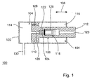
- FIG. 1 schematically shows a cylinder 100 (lifting device) shown, which includes a cylinder 102 in the cavity 104, a piston element 106 is arranged movably (see arrow 108) is.
- the piston member 106 includes a piston section 110 and a rod portion 112.
- the piston portion 110 divides the cavity 104 of the cylinder 102 into a piston crown space 114 and a piston annulus 116.
- a valve unit 118 arranged over a first connection channel 120 is in communication with the piston crown space 114, and via a second connecting channel 122 with the piston annulus 116 is connected.
- the valve unit 118 is also included the ambient atmosphere, e.g. connected via a channel 123.
- the valve unit 118 comprises a valve piston 124, the spring 126 in one, preferably adjustable Is biased in the direction in which the piston element is retracted becomes.
- the illustrated design of the second connecting channel 122 are also other configurations possible as long as it is ensured that the pressure from the annulus not in the axial direction on the piston 124 of the valve unit 118 acts.
- the piston section 110 further comprises the piston element 106 a valve device 128, for example in the form of a biased into the closed position by a spring Check valve.
- the valve device 128 is between the piston crown space 114 and the piston annulus 116 switched.
- the valve device 128 is provided to a Ensure compensation of hydraulic fluid in the lifting device. When the piston element 106 is retracted the pressure rising in the floor space 114 is finally one Opening the valve 128 so that hydraulic fluid in the Annulus 116 can flow.
- the lifting device 100 comprises a connection 130, through which the piston crown 114 with a hydraulic pump is connectable.
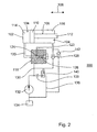
- FIG. 2 is a schematic of a second embodiment of the present invention only differs from the first embodiment in that that the valve unit 118 outside the cylinder 102 is arranged. 2 are the same or similar acting Elements already described with reference to FIG. 1 have been provided with the same reference numerals, and on a new description of the same is omitted.
- valve unit 118 is for example arranged in a block on an outside of the Cylinder 102 can be flanged and is via the connecting channels 120, 122 with the piston crown space 114 and the Piston annulus 116 connected.
- the valve device 128 is unlike the embodiment in Fig. 1, in one Connection line between the second connection channel 122 or the annular space 116 and the connection 130 arranged, functionally however identical to the arrangement from FIG. 1.
- FIG. 2 shows the pump 132, by means of the hydraulic fluid, e.g. Oil from a hydraulic fluid reservoir 134 is promoted.
- the pump 132 delivers in the direction shown and further is a reflux branch 136 shown over which when retracting the cylinder Hydraulic fluids of the reservoir 134 flows back.
- a Aperture 138 is in the return path before a check valve 140 arranged.
- FIGS. 1 and 2 are concerned a normal non-telescopic cylinder; however finds the present invention also use in the field of single-acting Telescopic cylinder, as follows based on the Fig. 4 will be explained.
- the piston element 106 is according to the present invention by a double acting stage formed, namely by the piston portion 110 and Rod section 112, whereby the annulus or piston annulus 116 is defined.
- the valve unit or valve arrangement 118 inside of the piston rod 112 (Fig. 1) consists of the valve piston 124 with valve seat and a compression spring 126, which holds the valve unit 118 closed, so that in Idle state no connection from the piston ring space 116 to the piston crown space 114 exists.
- Check valve 128 in the piston section 110 only bypasses when retracting the cylinder Valve unit 118 to the piston annulus 116 when retracting to be filled with oil.
- valve piston 124 As long as that generated by the pressure in the piston chamber 114 Force acting on the piston 124 is less than the spring force, the valve piston 124 is closed by the spring 126 held so that the piston annulus 116 completely is separated from the piston crown space 114.
- the valve piston is designed so that no force in the axial Direction, that is, in the direction in which the piston element 106 is moved, is exerted on the valve piston. So he is pressure balanced in this direction. However, the pressure from the piston crown space 114 directly via the valve piston 120 against the spring force of spring 126. If the pressure exceeds Spring force, the valve piston 124 opens and it becomes one Connected to piston annulus 116 until the pressure falls under the spring force again.
- the piston 104 and that Piston element 106 dimensioned such that in the annular space 116 a pressure of 200 bar is created with a tensile force of around 1.1 t.
- a pressure of the piston about 40 mm and the diameter of the piston element about 30 mm.
- a pressure of e.g. about 20 bar applied to the floor space 114, the valve unit in this case is dimensioned so that it at opens at a pressure of 20 bar.
- FIGS. 1 and 2 there is a Entry only possible with load.
- the cylinder of Fig. 1st or Fig. 2 develops none when a tensile force is applied Reaction pressure and does not include a pressure limiting device.
- the cylinders should therefore be dimensioned such that they withstand a maximum pressure in the annulus 116.
- the pressure generated in this room depends on of the tensile load, the diameters of the piston and the Piston element and the pressure applied by the pump, that according to the gear ratio in addition to the pressure acts in the annular space 116.
- To overpressure and therefore one to prevent possible damage to the cylinder the following measures are taken to build to avoid overpressure.
- the Spring 126 should be selected so that it is only a small one Pressure, e.g. less than 20 bar, resists and at one opens higher pressure. This causes the pump to must convey a low pressure to extend the cylinder. Due to the low pressure there is opposite only a small increase in pressure in the annular space, that does not pose a danger to the cylinder.
- a pressure relief valve may be provided, such as that in 2 is shown at 142. There it is a Check valve located between the annulus 116 and the tank 134 is switched. Check valve 142 opens when the pressure in the annulus exceeds a predetermined value.
- FIG. 3A Another embodiment to avoid overpressure is shown in Fig. 3A.
- Fig. 3A they are already based on the previous Figs. described elements with are given the same reference numerals and they are not described again.
- Fig. 3A differs Embodiment of the previous embodiments through the design of the piston element 124.
- the valve unit 118 is arranged in a cavity 150, and piston member 124 includes a first portion 152 and a second section 154.
- the first section 152 extends from the first connection portion 120 to the second section 154, which in turn continues to the Spring 126 extends. The spring presses against the second section 154th
- the first section 152 is designed such that in the closed position of the valve unit 118 of the first connecting section 120 is closed. Further extends the first section 152 does not cover the cavity wall 150 so that the inlet of the second connecting portion 122 spaced from the first section 152.
- the second section 154 follows the first section 152 and extends such that the second section with the wall of the cavity is in contact. Using seals 156 in the second section 154 there is a seal between Piston element 124 and spring 126.
- the pressure acts from the inlet of the connecting portion 122 in the annular space 116 partly on the surface 158 of the second section.
- This area is arranged so that a pressure in the annulus that exceeds a maximum permissible pressure, causes valve unit 118 to open.
- the dimensioning is, however, that this only occurs when a predetermined value is exceeded maximum pressure in the annular space 116.
- the existing pressure in the Annulus no opening of valve 118.
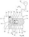
- FIG. 3B A further exemplary embodiment is shown in FIG. 3B.
- 3B are those already described with reference to FIG. 3A Provide elements with the same reference numerals and these are not described again.
- this embodiment includes instead, a bore 160 through the piston member 124, so that the bottom space 114 with the spring space 162nd connected is.
- a hydraulic accumulator 164 is also provided, which is connected to the annular space 116 via a line 166 is.
- Fig. 3B takes place its use in systems (e.g. single cylinder, telescopic cylinder), where e.g. halfway through the stroke basically reverses the force into a pulling force and the cylinder can no longer be retracted. outgoing of the fully retracted state occurs when the vehicle is extended following.
- systems e.g. single cylinder, telescopic cylinder
- e.g. halfway through the stroke basically reverses the force into a pulling force and the cylinder can no longer be retracted.
- outgoing of the fully retracted state occurs when the vehicle is extended following.
- the cylinder only moves when the hydraulic accumulator 166 accordingly is filled and the pressure to extend is established. The cylinder will be required when reached Pressure extended.
- the piston element opens when the maximum pressure is reached 124, which is dimensioned accordingly. Going to happen now the pump pressure is released, the cylinder can retract again, because the hydraulic accumulator 164 due to the stored Pressure exerts a corresponding force on the annular space 116, as long as the tensile force is not the force acting in the annulus exceeds.
- the retraction force decreases with the retracted one Gone, but the traction on the cylinder will decrease also reverse or reduce at some point so that the cylinder will actually run in.
- the pump shall be.
- the hydraulic accumulator 164 is used in this example be designed for a maximum pressure of 300 bar and then be fully filled. Adjusts itself on the piston element 124 Pressure difference of 100 bar, this will open. The The spring force of spring 126 was selected accordingly. If this pressure difference of 100 bar is not reached, so the cylinder loses this compressive force because of it a load is simulated. Is the pressure difference greater than 100 bar, the piston element 124 opens so that never higher than the force corresponding to 100 bar can be generated.
- FIG. 3B works just like that shown in Fig. 3A. Also at Telescopic cylinders (see Fig. 4) can this embodiment be used, e.g. with tippers. That in Fig. 3B
- the exemplary embodiment shown is preferably used if the annular space is relatively small compared to the piston space and only a small restoring force is required.
- a preferred exemplary embodiment is described below with reference to FIG. 4 described a synchronous telescopic cylinder.
- the synchronous cylinder 300 comprises a cylinder 302, which includes a jacket 302a and a bottom 302b.
- a first cylinder / piston unit 304 arranged in the cylinder 302 in the cylinder 302 .
- a second cylinder / piston unit 308 in a cavity 306 of the first cylinder / piston unit 304 is a second cylinder / piston unit 308 arranged in a cavity 306 of the first cylinder / piston unit 304 arranged.
- a first valve 310 is adjacent to the cavity 306 the first cylinder / piston unit 304 and is effective to in the rest position of the synchronous cylinder shown in Fig. 4 300 to be in the open state, which is Valve 310 is otherwise closed.
- the valve 310 includes a first check valve 312, which through a hemisphere is formed.
- Bottom 302b includes a first pin 314.
- Check valve 312 is via a first spring 316 biased.
- the pin 314 can be adjusted to ensure that valve 310 is in its rest position is open, which is particularly important if a force F acting on the cylinder 300 is not continuous works if the loading area e.g. before reaching the bottom Position already lies on a stop.
- the cylinder 300 is based on a fixed rest position extended and this fixed rest position results e.g. by the position of the pistons after retraction the same if e.g. a loading area already on one Stop of a frame of a vehicle rests so that no more force works. In such a case, the lowest piston with its piston section not the cylinder bottom.
- the cylinder is in the one just described Rest position or in an arbitrarily extended Position, the valve device is effective to move in one direction to be freely flowable in the piston annulus, whereas the valve unit in one direction out of the cavity is closed out. In the event of a deviation from the rest position such that the pistons relative to the rest position the valve device is effective, to both into and out of the cavity out to be freely flowable.
- the rest position described above is reached when the cylinder is effective as the lower stop and the lowest piston reaches this stop, whereby in in this case until one reaches this lower stop Power works.
- the piston is in this fixed Rest position, the valve device is effective to enter the Direction into the cavity and in the direction from the Cavity to be freely flowable. Is located the piston element in any extended position, the valve device is effective to move in one direction to be freely flowable into the cavity, whereas the valve unit in one direction out of the cavity closed is.
- the cylinder 302 includes a cylinder bottom space 320 and a cylinder annulus 322 defined by the first cylinder / piston unit 304 are separated. More specifically is the cylinder / piston unit 304 by a piston section 324 and a cylinder section 326, wherein the piston section 324 the cylinder bottom space 320 and separates the cylinder annulus 322 from each other.
- An opening 328 that extends through cylinder 302 connects the cylinder floor space 320 via a line 329 with a connection 330, through which during operation and for starting up the synchronous cylinder 300 a hydraulic fluid is introduced, which via a Pump is supplied from a hydraulic fluid tank.
- a hydraulic fluid is introduced, which via a Pump is supplied from a hydraulic fluid tank.
- a seal between the cylinder bottom space 320 and the Ensure cylinder annulus 322 is the piston section 324 of the first cylinder / piston unit 304 with sealing element (not shown).
- the first stage I of the synchronous cylinder 300 moves during operation of the cylinder through an opening 336 in the cylinder 302, in the area of the inner wall of the Opening 336 sealing elements are recessed to the required Sealing against the first cylinder / piston unit 304 to bring about.
- the first cylinder / piston unit also comprises 304 an opening 340 through which move the second stage II out while the cylinder is operating can. To face the required tightness level II, are again in the inner wall the opening 340 sealing elements arranged.
- the Cylinder annulus 322 projects over at least one opening 346 with the cavity 306 of the first cylinder / piston unit 304 in connection.
- Cylinder 302 also includes the first cylinder / piston unit 304 attacks against which the first stage I and the second stage II, if these are in their fully extended position.
- the second cylinder / piston unit 308 includes a cylinder section 360 and a piston section 362, and one Cavity 364, in which a piston 366 is arranged, which forms the stage III of the synchronous cylinder 300.
- the piston portion 362 of the second cylinder / piston unit 308 divides the cavity 306 of the first cylinder / piston unit 304 in an annular space 368 and in a floor space 370.
- Similar to the piston section 324 also has piston portion 362 of the second Cylinder / piston unit 308 sealing elements.
- the annular space 368 via a bore or opening 374 with the Cavity 364 of the second cylinder / piston unit 308 connected.
- a second valve 380 is provided that connects to the cavity 364 of the second cylinder / piston unit 308 adjoins, and the in the rest position of the second cylinder / piston unit shown in FIG. 4 is open and otherwise closed is. Similar to the first valve 310, the second also includes Valve 380 is a check valve which is in the form of a Hemisphere is formed, which is biased by a spring is. A pin is also provided, which ensures that the valve is open in the rest position shown in Fig. 4 is. The pin is dimensioned so that it is in the Rest position of cylinder 300 ensures that the second Valve 380 is open.
- valve unit 418 is arranged in the piston member 366, the a piston portion 410 and a rod portion 412. As a result, the cavity 364 becomes a piston crown space 441 and a piston annulus 416 divided.
- the valve unit 418 is via a first connection channel 420 with the piston crown space 414 and via a second connecting channel 422 connected to the piston annulus 416.
- the Valve unit 418 includes a valve piston 424 with a Valve seat 424a.
- the spring presses against the valve piston 424 426 to keep it in its closed position.
- the spring force of spring 426 is via an adjusting screw 450 adjustable.
- the valve unit 118 is e.g. about the Thread of the adjusting screw of the spring with the ambient atmosphere connected.
- the operation of the cylinder shown in Fig. 4 corresponds essentially to that of the arrangements 1 and 2.
- This traction is on the Piston annulus 368 with a correspondingly lower pressure of less than 80 bar.
- the oil in this annulus works on the piston section 410 and on the valve piston 424, that does not open under a pressure of 80 bar. So moved the second cylinder / piston unit 308 and nor the cylinder / piston unit 304.
- a hydraulic fluid is fed into the Cylinder 300 is inserted, and it is assumed that on the Piston rod 366 a force F (F> 500kp [4903.325 N]) overloaded.
- F force overloaded.
- still no hydraulic fluid e.g. B. hydraulic oil
- located within the synchronous cylinder 300 fills up first the cylinder floor space 320 with hydraulic fluid, and via the valve there is a connection to floor space 370 of the first cylinder / piston unit 304, and this is filled with hydraulic fluid.
- About the one or the plurality of bores 346 will also become the cylinder annulus Fill 322 with hydraulic fluid.
- the first valve 310 When entering the individual stages, when the In the rest position, the first valve 310 is opened. The other valve will open if too much in levels II and III or too little hydraulic fluid is available.
- the volume of the piston annulus is calculated so that it Volume of the rod section corresponds.
- the lifting device is designed so that to simulate a force of 500 kp (4903.325 N) the back pressure must be 350 bar in the piston annulus. This Pressure can only be generated without external forces if there is at least 80 bar pressure in the piston crown space.
- the spring force of the spring is 24 kp (235.3596 N), so that the valve piston at proportional to a pressure of 80 bar in the piston crown space opens.
- the pressure in the piston ring space does not act as a force on the valve piston, so this is, as already mentioned, pressure balanced, while the pressure in the piston crown space Outside pressure (air pressure) and the pressure spring force opposes.
Landscapes
- Engineering & Computer Science (AREA)
- Fluid Mechanics (AREA)
- Mechanical Engineering (AREA)
- General Engineering & Computer Science (AREA)
- Physics & Mathematics (AREA)
- Actuator (AREA)
- Advancing Webs (AREA)
- Noodles (AREA)
- Electrical Discharge Machining, Electrochemical Machining, And Combined Machining (AREA)
- Types And Forms Of Lifts (AREA)
- Braking Arrangements (AREA)
- Tumbler Switches (AREA)
- Crystals, And After-Treatments Of Crystals (AREA)
- Forklifts And Lifting Vehicles (AREA)
Description
einem Zylinder mit einem Hohlraum;
einem Kolbenelement, das in dem Hohlraum des Zylinders angeordnet ist, wobei das Kolbenelement einen Kolbenabschnitt und einen Stangenabschnitt umfaßt, wobei der Kolbenabschnitt den Hohlraum des Zylinders in einen Kolbenbodenraum und in einen Kolbenringraum unterteilt; und
einer Ventileinheit mit einem Ventilkolben, die dem Kolbenelement zugeordnet ist und bis zu einem vorbestimmten Druck im Kolbenbodenraum geschlossen ist, um den Kolbenbodenraum von dem Kolbenringraum zu trennen, und die oberhalb dieses Drucks durchströmbar ist;
wobei die Ventileinheit derart angeordnet ist, daß ein Druck in dem Kolbenringraum nicht in Schließrichtungen des Ventilkolbens auf die Ventileinheit wirkt und wobei ein in dem Kolbenringraum enthaltenes Fluid bei geöffneter Ventileinheit von dem Kolbenringraum in den Kolbenbodenraum fließt.
- Fig. 1
- eine schematische Darstellung eines Einfachzylinders gemäß einem ersten Ausführungsbeispiel der vorliegenden Erfindung, bei dem die Ventileinheit in dem Kolbenelement angeordnet ist;
- Fig. 2
- eine schematische Darstellung eines Einfachzylinders gemäß einem zweiten Ausführungsbeispiel der vorliegenden Erfindung, bei dem die Ventileinheit außerhalb des Zylinders angeordnet ist;
- Fig. 3A
- eine vergrößerte Darstellung der Ventileinheit aus Fig. 1 gemäß einem weiteren Ausführungsbeispiel;
- Fig. 3B
- eine Ventileinheit ähnlich zu der aus Fig. 3A mit einem Hydrospeicher; und
- Fig. 4
- eine schematische Darstellung eines Mehrfach-Zylinders mit der erfindungsgemäßen Auszugssperre gemäß dem ersten Ausführungsbeispiel.
Claims (12)
- Hubvorrichtung mit
einem Zylinder (102; 302) mit einem Hohlraum (104; 306)
einem Kolbenelement (106; 366), das in dem Hohlraum (104; 306) des Zylinders (102; 302) angeordnet ist, wobei das Kolbenelement (106; 366) einen Kolbenabschnitt (110; 410) und einen Stangenabschnitt (112; 412) umfaßt, wobei der Kolbenabschnitt (110; 410) den Hohlraum (104; 306) des Zylinders (102; 302) in einen Kolbenbodenraum (114; 414) und in einen Kolbenringraum (116; 416) unterteilt; und
einer Ventileinheit (118; 418) mit einem Ventilkolben (124; 424), die dem Kolbenelement (106; 366) zugeordnet ist und bis zu einem vorbestimmten Druck im Kolbenbodenraum (114; 414) geschlossen ist, um den Kolbenbodenraum (114; 414) von dem Kolbenringraum (116; 416) zu trennen, und die oberhalb dieses Drucks durchströmbar ist;
wobei die Ventileinheit (118; 418) derart angeordnet ist, daß ein Druck in dem Kolbenringraum (116; 416) nicht in Schließrichtungen (108) des Ventilkolbens (124; 424) auf die Ventileinheit (118; 418) wirkt und wobei ein in dem Kolbenringraum (116; 416) enthaltenes Fluid bei geöffneter Ventileinheit (118; 418) von dem Kolbenringraum (116; 416) in den Kolbenbodenraum (114; 414) fließt. - Hubvorrichtung nach Anspruch 1, bei dem die Ventileinheit (118; 418) derart angeordnet ist, daß ein Druck in dem Kolbenringraum (116; 416) nicht als Kraft auf den Ventilkolben (124; 424) der Ventileinheit (118; 418) wirkt.
- Hubvorrichtung nach Anspruch 1 oder 2, bei der die Ventileinheit (118; 418) über einen ersten Verbindungsabschnitt (120; 420) mit dem Kolbenbodenraum (114; 414) und über einen zweiten Verbindungsabschnitt (122; 422) mit dem Kolbenringraum verbunden ist.
- Hubvorrichtung nach einem der Ansprüche 1 bis 3, bei der die Ventileinheit (118; 418) ein Federelement (126; 426) umfaßt, das den Ventilkolben (124; 424) in eine geschlossene Stellung vorspannt.
- Hubvorrichtung nach Anspruch 4, bei der die Ventileinheit (418) eine Einstellschraube (450) umfaßt, um eine Vorspannungskraft des Federelements (426) einzustellen.
- Hubvorrichtung nach einem der Ansprüche 1 bis 5, bei der die Ventileinheit (118; 418) in dem Kolbenelement (106; 366) angeordnet ist.
- Hubvorrichtung nach Anspruch 6, bei der die Ventileinheit (118; 418) in dem Stangenabschnitt (112; 412) des Kolbenelements (106; 366) angeordnet ist, wobei sich der erste Verbindungsabschnitt (120; 420) im wesentlichen parallel zu der Richtung, entlang der das Kolbenelement (106; 366) bewegbar ist, erstreckt, wobei sich der zweite Verbindungsabschnitt (122; 422) unter einem Winkel zu der Richtung, entlang der das Kolbenelement (106; 366) bewegbar ist, erstreckt.
- Hubvorrichtung nach einem der Ansprüche 1 bis 5, bei der die Ventileinheit außerhalb des Zylinders (102) angeordnet ist.
- Hubvorrichtung nach einem der Ansprüche 1 bis 8, mit
einer Zylinder/Kolbeneinheit (304), die in dem Zylinder (302) angeordnet ist, wobei das Kolbenelement (366) in einem Hohlraum der Zylinder/Kolbeneinheit (304) angeordnet ist; und
einer Ventileinrichtung (310), die an den Hohlraum (306) in der Zylinder/Kolbeneinheit (304) angrenzt, wobei die Ventileinrichtung (310) in einer Ruhestellung oder bei
einer Abweichung aus der Ruhestellung derart, daß die Zylinder/Kolbeneinheit (304) gegenüber der Ruhestellung weiter eingefahren ist, frei durchströmbar ist und ansonsten geschlossen ist. - Hubvorrichtung nach Anspruch 9, bei der die Ventileinrichtung (310) folgende Merkmale aufweist:ein Rückschlagventil (312), das wirksam ist, um die Ventileinrichtung (310) in dem geschlossenen Zustand zu halten; undein Stiftbauglied (314), das mit dem Rückschlagventil (312) derart Eingriff nimmt, daß die Ventileinrichtung in der Ruhestellung oder bei der Abweichung aus der Ruhestellung der Zylinder/Kolbeneinheit (304) in dem geöffneten Zustand ist.
- Hubvorrichtung nach Anspruch 10, bei der das Stiftbauglied (314) einen einstellbaren Stift aufweist, um den Öffnungsgrad der Ventileinrichtung (310) in der Ruhestellung der Zylinder/Kolbeneinheit (304) einzustellen.
- Hubvorrichtung nach Anspruch 11, mit einem Anschluß (330), um ein Fluid in den Zylinderbodenraum (320) einzubringen, wobei der Anschluß (330) über die Ventileinrichtung (310) mit dem Hohlraum (306) der Zylinder/Kolbeneinheit (304) fluidmäßig verbindbar ist.
Applications Claiming Priority (3)
| Application Number | Priority Date | Filing Date | Title |
|---|---|---|---|
| DE10030545 | 2000-06-21 | ||
| DE10030545A DE10030545A1 (de) | 2000-06-21 | 2000-06-21 | Hubvorrichtung |
| PCT/EP2001/006985 WO2001098671A1 (de) | 2000-06-21 | 2001-06-20 | Hubvorrichtung |
Publications (3)
| Publication Number | Publication Date |
|---|---|
| EP1295042A1 EP1295042A1 (de) | 2003-03-26 |
| EP1295042B1 true EP1295042B1 (de) | 2004-03-03 |
| EP1295042B8 EP1295042B8 (de) | 2004-09-15 |
Family
ID=7646490
Family Applications (1)
| Application Number | Title | Priority Date | Filing Date |
|---|---|---|---|
| EP01951615A Expired - Lifetime EP1295042B8 (de) | 2000-06-21 | 2001-06-20 | Hubvorrichtung |
Country Status (9)
| Country | Link |
|---|---|
| EP (1) | EP1295042B8 (de) |
| AT (1) | ATE261068T1 (de) |
| AU (1) | AU2001272496A1 (de) |
| DE (2) | DE10030545A1 (de) |
| DK (1) | DK1295042T3 (de) |
| ES (1) | ES2215917T3 (de) |
| PT (1) | PT1295042E (de) |
| TR (1) | TR200401212T4 (de) |
| WO (1) | WO2001098671A1 (de) |
Families Citing this family (2)
| Publication number | Priority date | Publication date | Assignee | Title |
|---|---|---|---|---|
| GB0513278D0 (en) * | 2005-07-01 | 2005-08-03 | Delphi Tech Inc | Head restraint system |
| WO2007003267A2 (de) * | 2005-07-01 | 2007-01-11 | Delphi Technologies, Inc. | Auslösevorrichtung |
Family Cites Families (6)
| Publication number | Priority date | Publication date | Assignee | Title |
|---|---|---|---|---|
| US1812577A (en) * | 1928-04-27 | 1931-06-30 | Rogers Products Company Inc | Lifting jack |
| FR1067966A (fr) * | 1951-09-11 | 1954-06-21 | Sperry Gyroscope Co Ltd | Servo-moteur hydraulique utilisable notamment avec les dispositifs de pilotage automatique pour avions |
| US3450006A (en) * | 1968-01-29 | 1969-06-17 | Timberjack Machines Ltd | Cylinder and piston assembly with automatic power release |
| FR2547290B1 (fr) * | 1983-06-07 | 1987-04-30 | Rassant Sa Ets F | Cric hydraulique a limiteur de course perfectionne |
| DE19627974C2 (de) * | 1996-07-11 | 2003-02-06 | Getrag Getriebe Zahnrad | Hydraulische Stelleinheit und Verfahren zum Entlüften einer hydraulischen Stelleinheit |
| DE29900850U1 (de) * | 1999-01-20 | 1999-04-29 | Festo AG & Co, 73734 Esslingen | Fluidbetätigter Linearantrieb |
-
2000
- 2000-06-21 DE DE10030545A patent/DE10030545A1/de not_active Withdrawn
-
2001
- 2001-06-20 PT PT01951615T patent/PT1295042E/pt unknown
- 2001-06-20 TR TR2004/01212T patent/TR200401212T4/xx unknown
- 2001-06-20 AU AU2001272496A patent/AU2001272496A1/en not_active Abandoned
- 2001-06-20 ES ES01951615T patent/ES2215917T3/es not_active Expired - Lifetime
- 2001-06-20 EP EP01951615A patent/EP1295042B8/de not_active Expired - Lifetime
- 2001-06-20 WO PCT/EP2001/006985 patent/WO2001098671A1/de not_active Ceased
- 2001-06-20 DK DK01951615T patent/DK1295042T3/da active
- 2001-06-20 DE DE50101629T patent/DE50101629D1/de not_active Expired - Fee Related
- 2001-06-20 AT AT01951615T patent/ATE261068T1/de active IP Right Revival
Also Published As
| Publication number | Publication date |
|---|---|
| DE50101629D1 (de) | 2004-04-08 |
| ES2215917T3 (es) | 2004-10-16 |
| EP1295042B8 (de) | 2004-09-15 |
| AU2001272496A1 (en) | 2002-01-02 |
| ATE261068T1 (de) | 2004-03-15 |
| EP1295042A1 (de) | 2003-03-26 |
| DE10030545A1 (de) | 2002-01-10 |
| DK1295042T3 (da) | 2004-07-12 |
| PT1295042E (pt) | 2004-07-30 |
| WO2001098671A1 (de) | 2001-12-27 |
| TR200401212T4 (tr) | 2004-08-23 |
Similar Documents
| Publication | Publication Date | Title |
|---|---|---|
| DE3413866C2 (de) | Hydrostatisches Antriebssystem | |
| EP2024647A1 (de) | Hydrostatischer antrieb mit volumenstromausgleich | |
| DE3150643A1 (de) | Hydraulischer teleskopstempel, insbesondere fuer einen untertaegigen schreitausbau, wie vor allem schildausbaugestelle | |
| EP2220379B1 (de) | Hydraulische ventilvorrichtung | |
| DE10150238A1 (de) | Druckregelventil, insbesondere Proportional-Druckregelventil | |
| DE102015005920A1 (de) | Vorrichtung zur energieoptimierten hydraulischen Steuerung wenigstens eines doppeltwirkenden Arbeitszylinders | |
| DE102007036274B4 (de) | Hubzylinder und Hubvorrichtung | |
| DE4224973C2 (de) | Fluidversorgungssystem mit Druckbegrenzung | |
| AT503811B1 (de) | Hydraulische schaltungsanordnung zur betätigung eines hydraulischen arbeitszylinders | |
| EP1781952B1 (de) | Hydraulische steueranordnung | |
| DE19602166B4 (de) | Selbstpumpender hydropneumatischer Schwingungsdämpfer mit Einrichtungen zur variablen Steuerung der Dämpfungskraft | |
| DE102007025742A1 (de) | Hydrostatischer Antrieb mit Volumenstromausgleich | |
| DE69222861T2 (de) | Hydraulische schaltung mit druckausgleichventil | |
| EP1395753B1 (de) | Hochdruckpumpe für ein kraftstoffsystem einer brennkraftmaschine | |
| DE2517679A1 (de) | Nippel zum einfuellen von insbesondere fett | |
| DE102005051324A1 (de) | Spülventil für einen hydraulischen Kreislauf | |
| DE2522977A1 (de) | Fluiddruckverstaerker | |
| DE60020437T2 (de) | Überlastungsschutz für mechanische Presse | |
| DE3135098A1 (de) | Ventilaufbau, umfassend ein pumpensteuer- bzw. -regelventil und eine entlastungsanordnung | |
| EP1295042A1 (de) | Hubvorrichtung | |
| DE102021109704B4 (de) | Entsperrbares Rückschlagventil | |
| EP0296342A2 (de) | Bremsanlage | |
| DE102015121915A1 (de) | Pleuelstange und Verbrennungsmotor | |
| WO2004101263A1 (de) | Antrieb für eine stanz- oder umformmaschine | |
| DE2710440C2 (de) | Vorrichtung zur aktiven Schwingungsdämpfung |
Legal Events
| Date | Code | Title | Description |
|---|---|---|---|
| PUAI | Public reference made under article 153(3) epc to a published international application that has entered the european phase |
Free format text: ORIGINAL CODE: 0009012 |
|
| 17P | Request for examination filed |
Effective date: 20030111 |
|
| AK | Designated contracting states |
Kind code of ref document: A1 Designated state(s): AT BE CH CY DE DK ES FI FR GB GR IE IT LI LU MC NL PT SE TR |
|
| AX | Request for extension of the european patent |
Extension state: AL LT LV MK RO SI |
|
| GRAP | Despatch of communication of intention to grant a patent |
Free format text: ORIGINAL CODE: EPIDOSNIGR1 |
|
| RAP1 | Party data changed (applicant data changed or rights of an application transferred) |
Owner name: BRUGGER, CHRISTINA Owner name: BRUGGER, KLAUS Owner name: BRUGGER, GEORG MAXIMILIAN |
|
| RIN1 | Information on inventor provided before grant (corrected) |
Inventor name: BRUGGER, KLAUS Inventor name: BRUGGER, GEORG MAXIMILIAN Inventor name: BRUGGER, CHRISTINA |
|
| GRAS | Grant fee paid |
Free format text: ORIGINAL CODE: EPIDOSNIGR3 |
|
| GRAA | (expected) grant |
Free format text: ORIGINAL CODE: 0009210 |
|
| AK | Designated contracting states |
Kind code of ref document: B1 Designated state(s): AT BE CH CY DE DK ES FI FR GB GR IE IT LI LU MC NL PT SE TR |
|
| REG | Reference to a national code |
Ref country code: GB Ref legal event code: FG4D Free format text: NOT ENGLISH |
|
| REG | Reference to a national code |
Ref country code: CH Ref legal event code: EP |
|
| RAP2 | Party data changed (patent owner data changed or rights of a patent transferred) |
Owner name: BRUGGER, GEORG MAXIMILIAN Owner name: BRUGGER, CHRISTINA |
|
| RIN2 | Information on inventor provided after grant (corrected) |
Inventor name: BRUGGER, CHRISTINA Inventor name: BRUGGER, GEORG MAXIMILIAN |
|
| REG | Reference to a national code |
Ref country code: IE Ref legal event code: FG4D Free format text: GERMAN |
|
| REF | Corresponds to: |
Ref document number: 50101629 Country of ref document: DE Date of ref document: 20040408 Kind code of ref document: P |
|
| NLT2 | Nl: modifications (of names), taken from the european patent patent bulletin |
Owner name: BRUGGER, GEORG MAXIMILIAN EN BRUGGER, CHRISTINA |
|
| REG | Reference to a national code |
Ref country code: GR Ref legal event code: EP Ref document number: 20040401704 Country of ref document: GR |
|
| REG | Reference to a national code |
Ref country code: SE Ref legal event code: TRGR Ref country code: CH Ref legal event code: NV Representative=s name: PA ALDO ROEMPLER |
|
| PG25 | Lapsed in a contracting state [announced via postgrant information from national office to epo] |
Ref country code: TR Free format text: LAPSE BECAUSE OF FAILURE TO SUBMIT A TRANSLATION OF THE DESCRIPTION OR TO PAY THE FEE WITHIN THE PRESCRIBED TIME-LIMIT Effective date: 20040620 Ref country code: CY Free format text: LAPSE BECAUSE OF NON-PAYMENT OF DUE FEES Effective date: 20040620 |
|
| PG25 | Lapsed in a contracting state [announced via postgrant information from national office to epo] |
Ref country code: ES Free format text: LAPSE BECAUSE OF NON-PAYMENT OF DUE FEES Effective date: 20040621 |
|
| PG25 | Lapsed in a contracting state [announced via postgrant information from national office to epo] |
Ref country code: DK Free format text: LAPSE BECAUSE OF NON-PAYMENT OF DUE FEES Effective date: 20040630 |
|
| REG | Reference to a national code |
Ref country code: DK Ref legal event code: T3 |
|
| REG | Reference to a national code |
Ref country code: PT Ref legal event code: SC4A Free format text: AVAILABILITY OF NATIONAL TRANSLATION Effective date: 20040602 |
|
| GBT | Gb: translation of ep patent filed (gb section 77(6)(a)/1977) |
Effective date: 20040720 |
|
| REG | Reference to a national code |
Ref country code: GB Ref legal event code: ERR Free format text: NOTIFICATION HAS NOW BEEN RECEIVED FROM THE EUROPEAN PATENT OFFICE THAT THERE ARE ONLY TWO PROPRIETOR, DETAILS AS SHOWN BELOW: GEORG MAXIMILIAN BRUGGER CHRISTINA BRUGGER THIS CORRECTION WAS PUBLISHED IN THE EUROPEAN PATENT BULLETIN 04/12 DATED 20040317. |
|
| RIN2 | Information on inventor provided after grant (corrected) |
Inventor name: BRUGGER, KLAUS |
|
| LTIE | Lt: invalidation of european patent or patent extension |
Effective date: 20040303 |
|
| REG | Reference to a national code |
Ref country code: ES Ref legal event code: FG2A Ref document number: 2215917 Country of ref document: ES Kind code of ref document: T3 |
|
| ET | Fr: translation filed | ||
| PGFP | Annual fee paid to national office [announced via postgrant information from national office to epo] |
Ref country code: BE Payment date: 20041217 Year of fee payment: 4 |
|
| PGFP | Annual fee paid to national office [announced via postgrant information from national office to epo] |
Ref country code: GR Payment date: 20041220 Year of fee payment: 4 |
|
| PLBE | No opposition filed within time limit |
Free format text: ORIGINAL CODE: 0009261 |
|
| STAA | Information on the status of an ep patent application or granted ep patent |
Free format text: STATUS: NO OPPOSITION FILED WITHIN TIME LIMIT |
|
| RIN2 | Information on inventor provided after grant (corrected) |
Inventor name: BRUGGER, CHRISTINA Inventor name: BRUGGER, GEORG MAXIMILIAN |
|
| REG | Reference to a national code |
Ref country code: DK Ref legal event code: EBP |
|
| 26N | No opposition filed |
Effective date: 20041206 |
|
| REG | Reference to a national code |
Ref country code: PT Ref legal event code: MM4A Free format text: LAPSE DUE TO NON-PAYMENT OF FEES Effective date: 20041220 |
|
| PGFP | Annual fee paid to national office [announced via postgrant information from national office to epo] |
Ref country code: PT Payment date: 20050323 Year of fee payment: 4 |
|
| REG | Reference to a national code |
Ref country code: PT Ref legal event code: NF4A Free format text: RESTITUTIO IN INTEGRUM Effective date: 20050323 |
|
| PG25 | Lapsed in a contracting state [announced via postgrant information from national office to epo] |
Ref country code: SE Free format text: LAPSE BECAUSE OF NON-PAYMENT OF DUE FEES Effective date: 20050621 |
|
| PG25 | Lapsed in a contracting state [announced via postgrant information from national office to epo] |
Ref country code: FR Free format text: LAPSE BECAUSE OF NON-PAYMENT OF DUE FEES Effective date: 20050630 Ref country code: LU Free format text: LAPSE BECAUSE OF NON-PAYMENT OF DUE FEES Effective date: 20050630 Ref country code: BE Free format text: LAPSE BECAUSE OF NON-PAYMENT OF DUE FEES Effective date: 20050630 |
|
| PGFP | Annual fee paid to national office [announced via postgrant information from national office to epo] |
Ref country code: SE Payment date: 20050704 Year of fee payment: 5 |
|
| PGFP | Annual fee paid to national office [announced via postgrant information from national office to epo] |
Ref country code: IE Payment date: 20050728 Year of fee payment: 5 |
|
| REG | Reference to a national code |
Ref country code: ES Ref legal event code: FD2A Effective date: 20040621 |
|
| PG25 | Lapsed in a contracting state [announced via postgrant information from national office to epo] |
Ref country code: PT Free format text: LAPSE BECAUSE OF NON-PAYMENT OF DUE FEES Effective date: 20051220 |
|
| PG25 | Lapsed in a contracting state [announced via postgrant information from national office to epo] |
Ref country code: GR Free format text: LAPSE BECAUSE OF NON-PAYMENT OF DUE FEES Effective date: 20060103 |
|
| EUG | Se: european patent has lapsed | ||
| PG25 | Lapsed in a contracting state [announced via postgrant information from national office to epo] |
Ref country code: IE Free format text: LAPSE BECAUSE OF NON-PAYMENT OF DUE FEES Effective date: 20060620 |
|
| REG | Reference to a national code |
Ref country code: FR Ref legal event code: ST Effective date: 20060929 |
|
| PGFP | Annual fee paid to national office [announced via postgrant information from national office to epo] |
Ref country code: GB Payment date: 20061228 Year of fee payment: 6 |
|
| REG | Reference to a national code |
Ref country code: FR Ref legal event code: RN |
|
| REG | Reference to a national code |
Ref country code: IE Ref legal event code: MM4A |
|
| REG | Reference to a national code |
Ref country code: CH Ref legal event code: NV Representative=s name: PA ALDO ROEMPLER |
|
| REG | Reference to a national code |
Ref country code: FR Ref legal event code: FC |
|
| BERE | Be: lapsed |
Owner name: *BRUGGER GEORG MAXIMILIAN Effective date: 20050630 Owner name: *BRUGGER CHRISTINA Effective date: 20050630 |
|
| GBPC | Gb: european patent ceased through non-payment of renewal fee |
Effective date: 20070620 |
|
| PGFP | Annual fee paid to national office [announced via postgrant information from national office to epo] |
Ref country code: FR Payment date: 20070207 Year of fee payment: 7 |
|
| PG25 | Lapsed in a contracting state [announced via postgrant information from national office to epo] |
Ref country code: GB Free format text: LAPSE BECAUSE OF NON-PAYMENT OF DUE FEES Effective date: 20070620 |
|
| REG | Reference to a national code |
Ref country code: CH Ref legal event code: PCAR Free format text: ALDO ROEMPLER PATENTANWALT;BRENDENWEG 11 POSTFACH 154;9424 RHEINECK (CH) |
|
| PGFP | Annual fee paid to national office [announced via postgrant information from national office to epo] |
Ref country code: MC Payment date: 20090605 Year of fee payment: 9 Ref country code: NL Payment date: 20090604 Year of fee payment: 9 |
|
| PGFP | Annual fee paid to national office [announced via postgrant information from national office to epo] |
Ref country code: DE Payment date: 20090626 Year of fee payment: 9 |
|
| REG | Reference to a national code |
Ref country code: NL Ref legal event code: V1 Effective date: 20110101 |
|
| PG25 | Lapsed in a contracting state [announced via postgrant information from national office to epo] |
Ref country code: MC Free format text: LAPSE BECAUSE OF NON-PAYMENT OF DUE FEES Effective date: 20100630 |
|
| PG25 | Lapsed in a contracting state [announced via postgrant information from national office to epo] |
Ref country code: DE Free format text: LAPSE BECAUSE OF NON-PAYMENT OF DUE FEES Effective date: 20110101 |
|
| PG25 | Lapsed in a contracting state [announced via postgrant information from national office to epo] |
Ref country code: NL Free format text: LAPSE BECAUSE OF NON-PAYMENT OF DUE FEES Effective date: 20110101 |
|
| PGFP | Annual fee paid to national office [announced via postgrant information from national office to epo] |
Ref country code: FI Payment date: 20110324 Year of fee payment: 11 |
|
| PGFP | Annual fee paid to national office [announced via postgrant information from national office to epo] |
Ref country code: LU Payment date: 20110620 Year of fee payment: 11 |
|
| PGFP | Annual fee paid to national office [announced via postgrant information from national office to epo] |
Ref country code: CH Payment date: 20110907 Year of fee payment: 11 |
|
| PGFP | Annual fee paid to national office [announced via postgrant information from national office to epo] |
Ref country code: IT Payment date: 20120628 Year of fee payment: 12 |
|
| PG25 | Lapsed in a contracting state [announced via postgrant information from national office to epo] |
Ref country code: FI Free format text: LAPSE BECAUSE OF NON-PAYMENT OF DUE FEES Effective date: 20120620 |
|
| PGFP | Annual fee paid to national office [announced via postgrant information from national office to epo] |
Ref country code: AT Payment date: 20120629 Year of fee payment: 12 |
|
| REG | Reference to a national code |
Ref country code: CH Ref legal event code: PL |
|
| REG | Reference to a national code |
Ref country code: AT Ref legal event code: MM01 Ref document number: 261068 Country of ref document: AT Kind code of ref document: T Effective date: 20130620 |
|
| PG25 | Lapsed in a contracting state [announced via postgrant information from national office to epo] |
Ref country code: LI Free format text: LAPSE BECAUSE OF NON-PAYMENT OF DUE FEES Effective date: 20130630 Ref country code: CH Free format text: LAPSE BECAUSE OF NON-PAYMENT OF DUE FEES Effective date: 20130630 |
|
| PG25 | Lapsed in a contracting state [announced via postgrant information from national office to epo] |
Ref country code: IT Free format text: LAPSE BECAUSE OF NON-PAYMENT OF DUE FEES Effective date: 20130620 Ref country code: LU Free format text: LAPSE BECAUSE OF NON-PAYMENT OF DUE FEES Effective date: 20120620 Ref country code: AT Free format text: LAPSE BECAUSE OF NON-PAYMENT OF DUE FEES Effective date: 20130620 |
|
| PG25 | Lapsed in a contracting state [announced via postgrant information from national office to epo] |
Ref country code: FR Free format text: LAPSE BECAUSE OF NON-PAYMENT OF DUE FEES Effective date: 20060630 |