EP1294067B1 - Procédé d'installation d'un élément tubulaire - Google Patents
Procédé d'installation d'un élément tubulaire Download PDFInfo
- Publication number
- EP1294067B1 EP1294067B1 EP02292233A EP02292233A EP1294067B1 EP 1294067 B1 EP1294067 B1 EP 1294067B1 EP 02292233 A EP02292233 A EP 02292233A EP 02292233 A EP02292233 A EP 02292233A EP 1294067 B1 EP1294067 B1 EP 1294067B1
- Authority
- EP
- European Patent Office
- Prior art keywords
- tubular element
- cavity
- treatment
- compound
- fixing compound
- Prior art date
- Legal status (The legal status is an assumption and is not a legal conclusion. Google has not performed a legal analysis and makes no representation as to the accuracy of the status listed.)
- Expired - Lifetime
Links
Images


Classifications
-
- G—PHYSICS
- G02—OPTICS
- G02B—OPTICAL ELEMENTS, SYSTEMS OR APPARATUS
- G02B6/00—Light guides; Structural details of arrangements comprising light guides and other optical elements, e.g. couplings
- G02B6/46—Processes or apparatus adapted for installing or repairing optical fibres or optical cables
- G02B6/50—Underground or underwater installation; Installation through tubing, conduits or ducts
- G02B6/508—Fixation devices in ducts for drawing cables
-
- H—ELECTRICITY
- H02—GENERATION; CONVERSION OR DISTRIBUTION OF ELECTRIC POWER
- H02G—INSTALLATION OF ELECTRIC CABLES OR LINES, OR OF COMBINED OPTICAL AND ELECTRIC CABLES OR LINES
- H02G1/00—Methods or apparatus specially adapted for installing, maintaining, repairing or dismantling electric cables or lines
- H02G1/06—Methods or apparatus specially adapted for installing, maintaining, repairing or dismantling electric cables or lines for laying cables, e.g. laying apparatus on vehicle
- H02G1/08—Methods or apparatus specially adapted for installing, maintaining, repairing or dismantling electric cables or lines for laying cables, e.g. laying apparatus on vehicle through tubing or conduit, e.g. rod or draw wire for pushing or pulling
-
- H—ELECTRICITY
- H02—GENERATION; CONVERSION OR DISTRIBUTION OF ELECTRIC POWER
- H02G—INSTALLATION OF ELECTRIC CABLES OR LINES, OR OF COMBINED OPTICAL AND ELECTRIC CABLES OR LINES
- H02G9/00—Installations of electric cables or lines in or on the ground or water
- H02G9/06—Installations of electric cables or lines in or on the ground or water in underground tubes or conduits; Tubes or conduits therefor
Definitions
- the present invention relates to a method for the installation of a tubular element in an existing cavity.
- the tubular element can be a cable or pipe, and in particular a hollow tube intended to accommodate one or more cables.
- the cavity is in particular a tubular cavity, for example a network of pipelines for the collection of wastewater or rainwater.
- the invention relates more particularly operations taking place in tubular cavities non-pressurized subterranean small diameter, in particular less than 200mm in diameter, such as a sewer or drain pipe of one building, in which direct visual and material access is impossible.
- tubular element is fixed to the inner wall of a inaccessible cavity by fastening means regularly arranged.
- fastening means are fixed in advance on the inner wall of the cavity, the most often at the top, by an unmanned device.
- a problem is to ensure a solid and durable attachment of these means on the wall of the cavity whose constitutive material is variable.
- This type of process has the disadvantage to require the prior installation of the fastening means which constitutes a long and sometimes difficult operation.
- these fixing means constitute reliefs on the wall. These reliefs are likely to retain solid residues circulating in the duct, and interfere with subsequent cleaning operations.
- a solution to this problem was brought by the use of a coating covering the entire inner wall of the cavity.
- GB-2 124 728 describes the installation of a television cable in an existing sewer pipe.
- the cable is suspended from the ceiling of the cavity.
- this document proposes to use a material self-adhesive plastic wound spirally along the cavity, the cable being sandwich between the inner wall of the cavity and this coating material. Nevertheless, the setting up of such a coating is slow and expensive because the totality the surface of the cavity is covered with adhesive material. otherwise the adhesion to the wall of this coating is degraded over time. The consequences are that the maintenance of the cable is no longer ensured and that portions of the coating may become detached, in particular from the upper part of the cavity under the effect of gravity, causing at least partial obstruction of the cavity.
- JP-1 039 208 proposes to keep a cable in place by a coating of absorbent flexible material.
- This coating is introduced under shape of a pocket in the cavity thanks to a fluid under pressure.
- a resin of curing is sprayed onto the coating as it is introduction. This process is particularly expensive on the one hand because the the entire surface of the cavity is covered with the material and secondly with because of the importance of the external infrastructure required for spraying of resin.
- Document DE-198 61 090 mentions a method of bonding a cable fiber optic thanks to a layer of adhesive previously deposited on the object to to stare.
- a support device holds the object on the laying line and applies the adhesive on the wall.
- the adhesive layer can be temporarily covered a protective film to facilitate handling. In this case the film is removed thanks to a withdrawal device before pressing the body of the cable against the wall of the pipeline.
- This method has the disadvantage of not being applicable to a tubular element. Indeed to deposit on the object a sufficient quantity of adhesive product to obtain a good fixation, it must have a shape concave whose hollow contains the adhesive. Membership is obtained by flattening the concavity against the wall.
- the quality of the fixation of the object on the wall by this process is not sufficient because the adhesion of the object to the wall does not imply that a relatively small part of the periphery of the object, corresponding to the surface of the concavity. Moreover the adhesion will inevitably deteriorate in the time and the object will eventually come off the wall.
- Document DE-1 992 1382 which represents the most recent state of the art close, mentions a process installing a tubular element in a cavity through a layer of a adhesive compound previously deposited on the outer surface of the element tubular.
- the adhesive layer covers the entire outer periphery of item.
- a set comprising a pipe folded flat pressing the tubular element to be fixed and the adhesive layer.
- After positioning the assembly in the cavity folded pipe is filled with a gas or liquid to squeeze the element Tubular against the ceiling of the cavity during an activation treatment adhesive compound for securing the tubular member.
- an activation treatment adhesive compound for securing the tubular member.
- the present invention aims to eliminate the disadvantages of art prior art, and proposes for this purpose a method for the installation of an element tubular in an existing cavity that is quick and inexpensive while ensuring a more durable fixation.
- the combined formed by the tubular element associated with its fixing means is introduced into the cavity and positioned on the floor of the cavity.
- the tubular element may be made of plastic material, such as polyethylene, or metal such as steel which has the advantage of resisting to rodents. When it is hollow, it can be filled with a liquid during the activation treatment to counterbalance the Archimedes thrust imposed by the fixing compound when it is liquid.
- the tubular element is intended to be entirely embedded in the fixing compound, use is made of preferably a corrugated metal tubular element which has the advantage of weight. In the opposite case, the tubular element can be covered with metal only partially to resist rodents.
- the fixing compound can be constituted by a tubular envelope coaxial with said tubular element containing an adherent material in the viscous liquid state at room temperature, the assembly thus forming a thick layer all around the tubular element.
- said fixing compound comprises an adherent material selected among an adhesive, a resin, polyethylene, a cement, concrete and their mixtures.
- the fixing compound may further contain a repellent additive for to ward off rodents.
- the activation treatment is at least one treatment chosen from a heat treatment, chemical treatment and mechanical treatment.
- the Activation treatment fulfills two functions that ensure a strong fixation of the tubular element. On the one hand, it causes the deformation of the fixing compound to increase its contact area with the inner wall. And secondly it makes this compound adhere simultaneously to the inner wall and to the tubular element.
- a heat treatment may for example consist of sending a jet of high temperature steam inside a hollow tubular element for cause fusion of the fixing compound. You can also have a electric current to obtain the fusion of the fixing compound through the heat released by Joule effect when the tubular element is a hollow tube driver either because it is made of metal or because it has been coated with several metal strips along its length.
- Chemical treatment can be achieved by sending into the cavity a chemical compound capable of reacting with the fixing compound in order to to confer the necessary properties mentioned previously.
- chemical activation treatment may consist of sending into the cavity a compound likely to trigger a chemical reaction between some components of the fixing compound. For example in the simplest case we will use water to make the cement flow, which becomes water insensitive after solidification.
- the mechanical treatment may consist of tear in the pocket to reveal the material adherent, followed or not the evacuation of the pocket to the outside.
- said treatment activates said solid state fixing compound in the liquid state, from viscous preference.
- the fixing compound is then in the form of a liquid whose consistency is more or less thick depending on the conditions selected according to the expected result. In this state it covers the portion of the inner wall placed under the tubular element and on both sides of this one. Thus the fixing of the tubular element is reliably ensured, including included in the duration.
- the compound can fill the bottom of the cavity, even going up completely cover the tubular element.
- the irregularities of the wall to the part cavity are thus masked, and the floor of the cavity then presents a horizontal flat surface and relatively smooth.
- the process according to the invention has many advantages. It is simple to implement and faster than known methods. In particular, it avoids the prior implantation of the fixing means since these are introduced simultaneously with the tubular element. The asperities are reduced which facilitates a cleaning the cavity and on the other hand does not disturb the circulation in the cavity, including the flow of wastewater or rainwater. This process is usable in any type of cavity whatever its topology, even if the wall presents reliefs. On the contrary, this process has the advantage of concealing the defects of the part of the wall of the cavity on which the tubular element is fixed. Finally, the tubular element being deposited on the ground, the aging does not cause the negative consequences of the process of the prior art using a coating also covering the ceiling of the cavity.
- tubular element for accommodating cables, it allows its use without further intervention. At first we can do it pass fiber optic cables, but these cables can then be changed without inconvenience. It is even possible to change the destination of the tube hollow, subject to compatibility of materials, to use it for example as fluid conduit.
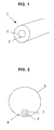
- a handset 1 comprises a tubular element 2 coated with a layer thick of a fixing compound 3, as shown in FIG.
- tubular 2 is for example a hollow tube with a diameter of less than 10 mm intended to receive one or more cables, including fiber optic cables used in telecommunications. Once the tube is installed, the cables in place can be changed or other cables can be added without the need to repeat the installation operations.
- Fixing compound 3 is for example a fuse glue that is solid at the operating temperature.
- the handset 1 is introduced into the cavity so as to rest on the ground 4 of the cavity 5 with a diameter of about 100 mm, as shown in FIG. Figure 2.
- the installation of handset 1 in cavity 5 is most often at least two phases.
- a first phase which is a phase of exploration and cleaning the walls of the cavity and another phase that is the installation of the handset 1 in the cavity 5, the handset 1 being driven in the cavity 5 by a mobile means and put in place.
- the cleaning of the walls of the cavity 5 can be carried out by any means known, but preferably use a remote-controlled mobile device comprising propulsive linear displacement means and means orientation in space. These means use jets of fluid under pressure and are hydraulically or pneumatically controlled.
- the mobile device can be equipped with a means of exploration and guidance, such as a gripping device view, of a lighting means, a means for locating the vertical, and / or a means of cleaning.
- This cleaning means may comprise fluid jets under pressure and a tool capable of exerting a physical action on the wall, like a scraper, a wire brush, an abrasive device or any other instrument capable of equalizing and sanitizing the inner surface of the wall of the pipe. This cleaning must be done carefully and completely, especially by abrasion, to guarantee good adhesion of the element tubular on the wall.
- the handset 1 For the introduction of the handset 1 in the cavity 5, it is possible to use a remotely controlled mobile device similar to that of the first phase.
- the handset 1 is towed by the apparatus and deposited at the desired location on the ground 4 5.
- traction means such as a cable or rope, which pulls the handset to the chosen location.
- the handset 1 is subjected to a treatment thermal activation.
- a stream of water vapor is injected into the hollow tube 2 of which the walls transmit the heat to the fuse glue layer 3.
- the glue 3 is softened then enough to sink and spread on both sides of the tube 2 as shown in Figure 3.
- the interruption of the steam intake allows the glue 3 to solidify while cooling, and to adhere strongly to the tube 2 on the one hand and the inner wall on the other hand.
- the surface portion 6 of the wall internal with which the glue 3 is in contact is represented by the arc of a circle between points A and B in Figure 3.
- the installation of tube 2 is final and allows its subsequent use without further intervention.
- the layer of the fixing compound 3 initially has a thickness corresponding to a volume of glue of the order of 1 to 4 times the volume of the tubular element by unit of length.
- the layer of the fixing compound 3 has initially a thickness corresponding to a volume of glue of the order of 4 to 8 times the volume of the tubular element per unit length.
- the glue after cooling has a flat horizontal surface 7 and free of roughness embarrassing.
- the tubular element 2 is preferably embedded in the adhesive 3 in order to avoid to form a relief on the surface 7.
- a tube is preferably used Ringed.
- Such a surface 7 has the double advantage of concealing the defects of the lower part of the wall of the cavity 5 and to provide a surface of Improved quality favorable to the use of the cavity 5 for other functions.
- the handset 50 of FIG. 5 consists of the tubular element 51 coated with a fixing compound consisting of an adherent material 52 having the consistency of a thick liquid, such as glue, enclosed in a pocket 53, for example polymer.
- This pocket 53 has a linear attenuation 54 parallel to the axis of the handset 50 intended to break mechanically to release the adhering material 52.
- the broken pouch is preferably evacuated so as not to impede the fixing of the tubular element on the wall.
- FIG. 6 illustrates the case where the pocket 63 does not include weakening.
- the handset 60 consists of the tubular element 61 covered of a fixing compound similar to that of Figure 5, consisting of a material adhering 62 enclosed in a pocket 63.
- the pocket 63 is removed by flipping and pulling on the flipped portion 64.
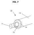
- FIG. combined 70 consists of the tubular element 71 covered with a compound of similar to that of FIG. 6.
- the bag 72 containing the material adherent 73 is terminated by a conical nozzle 74 whose end surrounds the tubular element 71 so as to provide a space filled with the material 73.
- pressure is applied to the end of the pocket 72 being outside.
- the pocket 72 is then torn then removed by pulling the nozzle 74.
- the layer of adherent material left on the tubular element 71 having the consistency of a thick liquid, spread on the wall of the cavity on each side of the tubular element 71.
Landscapes
- Physics & Mathematics (AREA)
- General Physics & Mathematics (AREA)
- Optics & Photonics (AREA)
- Electric Cable Installation (AREA)
- Adhesives Or Adhesive Processes (AREA)
- Cleaning In General (AREA)
- Details Of Indoor Wiring (AREA)
- Installation Of Indoor Wiring (AREA)
- Light Guides In General And Applications Therefor (AREA)
- Mechanical Treatment Of Semiconductor (AREA)
- Lining Or Joining Of Plastics Or The Like (AREA)
- Separation Using Semi-Permeable Membranes (AREA)
Description
- on prépare un combiné comprenant ledit élément tubulaire recouvert d'une couche d'un composé de fixation,
- on positionne ledit combiné le long de la surface interne de ladite cavité, et
- on effectue un traitement d'activation dudit composé de manière à fixer ledit élément tubulaire sur ladite surface interne, caractérisé en ce qu'on positionne ledit combiné sur le sol de la ladite cavité.
- la figure 1 représente un premier mode de réalisation d'un combiné avant son installation dans la cavité,
- la figure 2 représente le combiné de la figure 1 après son introduction dans la cavité,
- la figure 3 est une coupe de la cavité selon un premier mode de réalisation de l'invention montrant l'élément tubulaire après son installation, et
- la figure 4 est une coupe de la cavité selon un deuxième mode de réalisation de l'invention montrant l'élément tubulaire après son installation,
- la figure 5 représente un deuxième mode de réalisation d'un combiné avant son installation dans la cavité,
- la figure 6 représente un troisième mode de réalisation d'un combiné avant son installation dans la cavité,
- la figure 7 représente un quatrième mode de réalisation d'un combiné avant son installation dans la cavité.
Claims (11)
- Procédé d'installation d'un élément tubulaire (2; 51; 61; 71) dans une cavité (5), comprenant les étapes suivantes:on prépare un combiné (2, 3; 50; 60; 70) comprenant ledit élément tubulaire (2; 51; 61; 71) recouvert d'une couche d'un composé de fixation (3; 52; 62; 73),on positionne ledit combiné (2, 3; 50; 60; 70) le long de la surface interne de ladite cavité (5), eton effectue un traitement d'activation dudit composé de manière à fixer ledit élément tubulaire (2; 51; 61; 71) sur ladite surface interne, caractérisé en ce qu'on positionne ledit combiné (2, 3; 50; 60; 70) sur le sol de la ladite cavité (5).
- Procédé selon la revendication 1, dans lequel ledit élément tubulaire (2; 51; 61; 71) est en métal ou en matière plastique.
- Procédé selon l'une des revendications précédentes, dans lequel ledit élément tubulaire (2; 51; 61; 71) est annelé.
- Procédé selon l'une des revendications précédentes, dans lequel ledit composé de fixation est constitué d'une poche (53; 63; 72) contenant une matière adhérente (52; 62; 73).
- Procédé selon l'une des revendications précédentes, dans lequel ledit composé de fixation comprend une matière adhérente (52; 62; 73) choisie parmi une colle, une résine, le polyéthylène, un ciment, du béton et leurs mélanges.
- Procédé selon l'une des revendications précédentes, dans lequel ledit traitement d'activation fait passer ledit composé de fixation de l'état solide à l'état liquide.
- Procédé selon l'une des revendications précédentes, dans lequel ledit traitement d'activation est au moins un traitement choisi parmi un traitement thermique, un traitement chimique et un traitement mécanique.
- Procédé selon la revendication 7, dans lequel ledit traitement thermique consiste à envoyer de la vapeur à haute température à l'intérieur dudit élément tubulaire creux.
- Procédé selon la revendication 7, dans lequel ledit traitement thermique consiste à faire passer un courant électrique.
- Procédé selon la revendication 7, dans lequel ledit traitement chimique consiste à envoyer dans ladite cavité un composé chimique susceptible de déclencher une réaction chimique entre certains constituants dudit composé de fixation.
- Procédé selon la revendication 7, dans lequel ledit traitement mécanique consiste à perforer ladite poche.
Applications Claiming Priority (2)
| Application Number | Priority Date | Filing Date | Title |
|---|---|---|---|
| FR0111989 | 2001-09-17 | ||
| FR0111989A FR2829826B1 (fr) | 2001-09-17 | 2001-09-17 | Procede d'installation d'un element tubulaire |
Publications (2)
| Publication Number | Publication Date |
|---|---|
| EP1294067A1 EP1294067A1 (fr) | 2003-03-19 |
| EP1294067B1 true EP1294067B1 (fr) | 2005-06-08 |
Family
ID=8867352
Family Applications (1)
| Application Number | Title | Priority Date | Filing Date |
|---|---|---|---|
| EP02292233A Expired - Lifetime EP1294067B1 (fr) | 2001-09-17 | 2002-09-12 | Procédé d'installation d'un élément tubulaire |
Country Status (6)
| Country | Link |
|---|---|
| US (1) | US20030051808A1 (fr) |
| EP (1) | EP1294067B1 (fr) |
| JP (1) | JP2003199222A (fr) |
| AT (1) | ATE297603T1 (fr) |
| DE (1) | DE60204522D1 (fr) |
| FR (1) | FR2829826B1 (fr) |
Families Citing this family (2)
| Publication number | Priority date | Publication date | Assignee | Title |
|---|---|---|---|---|
| NL1023643C2 (nl) * | 2003-06-11 | 2004-12-20 | Hbg Civiel B V | Tunnel voor leidingen. |
| GB201712911D0 (en) | 2017-08-11 | 2017-09-27 | Nuron Ltd | Containment systems |
Family Cites Families (15)
| Publication number | Priority date | Publication date | Assignee | Title |
|---|---|---|---|---|
| GB1340068A (en) * | 1970-09-22 | 1973-12-05 | Insituform Pipes & Structures | Lining of surfaces defining passageways |
| US3758361A (en) * | 1970-11-16 | 1973-09-11 | J Hunter | Process for lining pipe joints |
| SE390802B (sv) * | 1973-11-27 | 1977-01-24 | Atomenergi Ab | Forfarande for sammanfogning av detaljer av fornetade polymerer |
| GB2124728B (en) | 1982-07-01 | 1985-11-13 | Micro Consultants Ltd | Cable television transmission |
| GB8412413D0 (en) * | 1984-05-16 | 1984-06-20 | Knowles A H | Permanent conforming flat pipe |
| WO1987004975A1 (fr) * | 1986-02-12 | 1987-08-27 | Tokyo Gas Kabushiki Kaisha | Procede de pose d'un revetement interieur de pipe-line |
| GB8608805D0 (en) * | 1986-04-11 | 1986-05-14 | Du Pont Uk | Thermoplastic polymer-lined pipe |
| JPS6439208A (en) | 1987-07-31 | 1989-02-09 | Tobu Cleaner Service | Cable laying construction in pipe and execution of work |
| GB9009899D0 (en) * | 1990-05-02 | 1990-06-27 | Du Pont Canada | Lining of metallic pipe |
| US5451351A (en) * | 1991-09-13 | 1995-09-19 | Composite Components, Inc. | Method for rehabilitating a pipe with a liner having an electrically conductive layer |
| CA2121711A1 (fr) * | 1993-05-03 | 1994-11-04 | Giulio Catallo | Tuyau flexible a gaine renforcee |
| GB2302153B (en) * | 1995-06-12 | 1999-10-20 | Wrc Plc | Pipeline renovation |
| DE19752424A1 (de) * | 1997-11-26 | 1999-05-27 | Siemens Ag | Verfahren zum Verlegen von Lichtwellenleiterkabeln in Rohrleitungen bestehender Versorgungsleitungssysteme |
| DE19921382C2 (de) * | 1998-10-16 | 2001-01-18 | Sabine Gruber | Verfahren zur Installation mindestens einer Leitung und/oder eines Leerrohrs in verlegten, zur Versorgung oder Entsorgung dienenden Rohren, insbesondere Kanalrohr-Systemen oder -Netzen und dgl. |
| DE19861090C2 (de) * | 1998-09-21 | 2002-11-28 | D T I Dr Trippe Ingenieurgmbh | Verfahren zum Verlegen von Verlegeobjekten in Kanälen, Vorrichtung zur Durchführung des Verfahrens, Verlegeroboter zur Durchführung des Verfahrens, sowie verlegtes Verlegeobjekt |
-
2001
- 2001-09-17 FR FR0111989A patent/FR2829826B1/fr not_active Expired - Fee Related
-
2002
- 2002-09-12 EP EP02292233A patent/EP1294067B1/fr not_active Expired - Lifetime
- 2002-09-12 AT AT02292233T patent/ATE297603T1/de not_active IP Right Cessation
- 2002-09-12 DE DE60204522T patent/DE60204522D1/de not_active Expired - Lifetime
- 2002-09-13 JP JP2002267751A patent/JP2003199222A/ja not_active Withdrawn
- 2002-09-16 US US10/243,679 patent/US20030051808A1/en not_active Abandoned
Also Published As
| Publication number | Publication date |
|---|---|
| US20030051808A1 (en) | 2003-03-20 |
| DE60204522D1 (de) | 2005-07-14 |
| EP1294067A1 (fr) | 2003-03-19 |
| ATE297603T1 (de) | 2005-06-15 |
| JP2003199222A (ja) | 2003-07-11 |
| FR2829826B1 (fr) | 2004-06-18 |
| FR2829826A1 (fr) | 2003-03-21 |
Similar Documents
| Publication | Publication Date | Title |
|---|---|---|
| EP1899638B1 (fr) | Pièce de raccordement de conduites comportant une chemise interne, procede de revetement et procede d'assemblage | |
| EP0115993B1 (fr) | Procédé de garnissage interne d'une conduite. | |
| EP1805444B1 (fr) | Conduite sous-marine comportant une chemise interne | |
| FR2480901A1 (fr) | Procede de garnissage interne d'une conduite | |
| EP2707641A1 (fr) | Dispositif et procede d'isolation thermique d'une zone de raccordement d'embouts de connexion de deux conduites sous-marines calorifugees. | |
| EP3303895B1 (fr) | Couverture amovible destinée à être disposée en regard d'une conduite de transport de fluide immergée dans une étendue d'eau, ensemble d'intervention et procédé associés | |
| EP1868020B1 (fr) | Procédé et dispositif d'installation de cables et gaines dans une canalisation non visitable | |
| FR2978229A1 (fr) | Calfeutrement de traversees de parois | |
| FR2542416A1 (fr) | Gaines autoporteuses pour conduites et procede d'introduction et de positionnement de ces gaines dans une conduite | |
| EP2044478A1 (fr) | Dispositf d'installation d'un cable dans un conduit | |
| EP1294067A1 (fr) | Procédé d'installation d'un élément tubulaire | |
| WO1998034061A1 (fr) | Enveloppe d'isolation thermique, notamment pour la construction de canalisations sous-marines vehiculant des produits petroliers | |
| FR3002376A1 (fr) | Bouchon d'etancheite pour cable electrique contre les infiltrations d'air dans les batiments et procede de pose du cable electrique | |
| EP0222643A1 (fr) | Procédé et dispositif de jointoyage d'éléments de conduite de transport de fluide | |
| EP1129313B1 (fr) | Conduit d'installation pour la construction d'un reseau de transport subaquatique de fluide, d'energie, ou de signaux | |
| EP0687850B1 (fr) | Gaine d'isolation thermique pour canalisation et son procédé de fabrication | |
| EP0432682A1 (fr) | Dispositif d'étanchéité longitudinale pour l'âme d'un câble optique | |
| FR2741472A1 (fr) | Protection biologique a partir d'alliages metalliques | |
| EP1097796A1 (fr) | Procédé pour entourer un élément par une couche de mousse, enveloppe en mousse, complexe tubulaire avec cette enveloppe, et couronne de ce complexe | |
| EP0743731A1 (fr) | Procédé et dispositif pour la mise en place de câbles de télécommunications à l'intérieur d'une conduite contenant déjà un câble existant | |
| FR2907609A1 (fr) | Procede d'installations de cables electriques et de fibres optiques en canalisations visitables et element de fixation pour sa mise en oeuvre | |
| FR2598772A1 (fr) | Tube de canalisation isole thermiquement, a deux conducteurs sans disposition pour la dilatation, procede et dispositif de leur mise en oeuvre. | |
| FR3120712A1 (fr) | Câble optique pour installation dans un fourreau par portage par un fluide | |
| BE698438A (fr) | ||
| FR2800664A1 (fr) | Procede pour entourer un element par une couche de mousse, enveloppe en mousse, complexe tubulaire avec cette enveloppe, et couronne de ce complexe |
Legal Events
| Date | Code | Title | Description |
|---|---|---|---|
| PUAI | Public reference made under article 153(3) epc to a published international application that has entered the european phase |
Free format text: ORIGINAL CODE: 0009012 |
|
| AK | Designated contracting states |
Kind code of ref document: A1 Designated state(s): AT BE BG CH CY CZ DE DK EE ES FI FR GB GR IE IT LI LU MC NL PT SE SK TR Designated state(s): AT BE BG CH CY CZ DE DK EE ES FI FR GB GR IE IT LI LU MC NL PT SE SK TR |
|
| AX | Request for extension of the european patent |
Extension state: AL LT LV MK RO SI |
|
| 17P | Request for examination filed |
Effective date: 20030919 |
|
| AKX | Designation fees paid |
Designated state(s): AT BE BG CH CY CZ DE DK EE ES FI FR GB GR IE IT LI LU MC NL PT SE SK TR |
|
| 17Q | First examination report despatched |
Effective date: 20040414 |
|
| GRAP | Despatch of communication of intention to grant a patent |
Free format text: ORIGINAL CODE: EPIDOSNIGR1 |
|
| GRAS | Grant fee paid |
Free format text: ORIGINAL CODE: EPIDOSNIGR3 |
|
| GRAA | (expected) grant |
Free format text: ORIGINAL CODE: 0009210 |
|
| AK | Designated contracting states |
Kind code of ref document: B1 Designated state(s): AT BE BG CH CY CZ DE DK EE ES FI FR GB GR IE IT LI LU MC NL PT SE SK TR |
|
| PG25 | Lapsed in a contracting state [announced via postgrant information from national office to epo] |
Ref country code: TR Free format text: LAPSE BECAUSE OF FAILURE TO SUBMIT A TRANSLATION OF THE DESCRIPTION OR TO PAY THE FEE WITHIN THE PRESCRIBED TIME-LIMIT Effective date: 20050608 Ref country code: SK Free format text: LAPSE BECAUSE OF FAILURE TO SUBMIT A TRANSLATION OF THE DESCRIPTION OR TO PAY THE FEE WITHIN THE PRESCRIBED TIME-LIMIT Effective date: 20050608 Ref country code: NL Free format text: LAPSE BECAUSE OF FAILURE TO SUBMIT A TRANSLATION OF THE DESCRIPTION OR TO PAY THE FEE WITHIN THE PRESCRIBED TIME-LIMIT Effective date: 20050608 Ref country code: IT Free format text: LAPSE BECAUSE OF FAILURE TO SUBMIT A TRANSLATION OF THE DESCRIPTION OR TO PAY THE FEE WITHIN THE PRESCRIBED TIME-LIMIT;WARNING: LAPSES OF ITALIAN PATENTS WITH EFFECTIVE DATE BEFORE 2007 MAY HAVE OCCURRED AT ANY TIME BEFORE 2007. THE CORRECT EFFECTIVE DATE MAY BE DIFFERENT FROM THE ONE RECORDED. Effective date: 20050608 Ref country code: IE Free format text: LAPSE BECAUSE OF FAILURE TO SUBMIT A TRANSLATION OF THE DESCRIPTION OR TO PAY THE FEE WITHIN THE PRESCRIBED TIME-LIMIT Effective date: 20050608 Ref country code: GB Free format text: LAPSE BECAUSE OF FAILURE TO SUBMIT A TRANSLATION OF THE DESCRIPTION OR TO PAY THE FEE WITHIN THE PRESCRIBED TIME-LIMIT Effective date: 20050608 Ref country code: FI Free format text: LAPSE BECAUSE OF FAILURE TO SUBMIT A TRANSLATION OF THE DESCRIPTION OR TO PAY THE FEE WITHIN THE PRESCRIBED TIME-LIMIT Effective date: 20050608 Ref country code: EE Free format text: LAPSE BECAUSE OF FAILURE TO SUBMIT A TRANSLATION OF THE DESCRIPTION OR TO PAY THE FEE WITHIN THE PRESCRIBED TIME-LIMIT Effective date: 20050608 Ref country code: CZ Free format text: LAPSE BECAUSE OF FAILURE TO SUBMIT A TRANSLATION OF THE DESCRIPTION OR TO PAY THE FEE WITHIN THE PRESCRIBED TIME-LIMIT Effective date: 20050608 Ref country code: AT Free format text: LAPSE BECAUSE OF FAILURE TO SUBMIT A TRANSLATION OF THE DESCRIPTION OR TO PAY THE FEE WITHIN THE PRESCRIBED TIME-LIMIT Effective date: 20050608 |
|
| REG | Reference to a national code |
Ref country code: GB Ref legal event code: FG4D Free format text: NOT ENGLISH |
|
| REG | Reference to a national code |
Ref country code: CH Ref legal event code: EP |
|
| REF | Corresponds to: |
Ref document number: 60204522 Country of ref document: DE Date of ref document: 20050714 Kind code of ref document: P |
|
| REG | Reference to a national code |
Ref country code: IE Ref legal event code: FG4D Free format text: LANGUAGE OF EP DOCUMENT: FRENCH |
|
| PG25 | Lapsed in a contracting state [announced via postgrant information from national office to epo] |
Ref country code: SE Free format text: LAPSE BECAUSE OF FAILURE TO SUBMIT A TRANSLATION OF THE DESCRIPTION OR TO PAY THE FEE WITHIN THE PRESCRIBED TIME-LIMIT Effective date: 20050908 Ref country code: GR Free format text: LAPSE BECAUSE OF FAILURE TO SUBMIT A TRANSLATION OF THE DESCRIPTION OR TO PAY THE FEE WITHIN THE PRESCRIBED TIME-LIMIT Effective date: 20050908 Ref country code: DK Free format text: LAPSE BECAUSE OF FAILURE TO SUBMIT A TRANSLATION OF THE DESCRIPTION OR TO PAY THE FEE WITHIN THE PRESCRIBED TIME-LIMIT Effective date: 20050908 Ref country code: BG Free format text: LAPSE BECAUSE OF FAILURE TO SUBMIT A TRANSLATION OF THE DESCRIPTION OR TO PAY THE FEE WITHIN THE PRESCRIBED TIME-LIMIT Effective date: 20050908 |
|
| PG25 | Lapsed in a contracting state [announced via postgrant information from national office to epo] |
Ref country code: DE Free format text: LAPSE BECAUSE OF FAILURE TO SUBMIT A TRANSLATION OF THE DESCRIPTION OR TO PAY THE FEE WITHIN THE PRESCRIBED TIME-LIMIT Effective date: 20050909 |
|
| PG25 | Lapsed in a contracting state [announced via postgrant information from national office to epo] |
Ref country code: CY Free format text: LAPSE BECAUSE OF FAILURE TO SUBMIT A TRANSLATION OF THE DESCRIPTION OR TO PAY THE FEE WITHIN THE PRESCRIBED TIME-LIMIT Effective date: 20050912 |
|
| PG25 | Lapsed in a contracting state [announced via postgrant information from national office to epo] |
Ref country code: ES Free format text: LAPSE BECAUSE OF FAILURE TO SUBMIT A TRANSLATION OF THE DESCRIPTION OR TO PAY THE FEE WITHIN THE PRESCRIBED TIME-LIMIT Effective date: 20050919 |
|
| PG25 | Lapsed in a contracting state [announced via postgrant information from national office to epo] |
Ref country code: MC Free format text: LAPSE BECAUSE OF NON-PAYMENT OF DUE FEES Effective date: 20050930 Ref country code: LU Free format text: LAPSE BECAUSE OF NON-PAYMENT OF DUE FEES Effective date: 20050930 Ref country code: BE Free format text: LAPSE BECAUSE OF NON-PAYMENT OF DUE FEES Effective date: 20050930 |
|
| PG25 | Lapsed in a contracting state [announced via postgrant information from national office to epo] |
Ref country code: PT Free format text: LAPSE BECAUSE OF FAILURE TO SUBMIT A TRANSLATION OF THE DESCRIPTION OR TO PAY THE FEE WITHIN THE PRESCRIBED TIME-LIMIT Effective date: 20051114 |
|
| NLV1 | Nl: lapsed or annulled due to failure to fulfill the requirements of art. 29p and 29m of the patents act | ||
| GBV | Gb: ep patent (uk) treated as always having been void in accordance with gb section 77(7)/1977 [no translation filed] |
Effective date: 20050608 |
|
| REG | Reference to a national code |
Ref country code: IE Ref legal event code: FD4D |
|
| PLBE | No opposition filed within time limit |
Free format text: ORIGINAL CODE: 0009261 |
|
| STAA | Information on the status of an ep patent application or granted ep patent |
Free format text: STATUS: NO OPPOSITION FILED WITHIN TIME LIMIT |
|
| 26N | No opposition filed |
Effective date: 20060309 |
|
| PG25 | Lapsed in a contracting state [announced via postgrant information from national office to epo] |
Ref country code: FR Free format text: LAPSE BECAUSE OF NON-PAYMENT OF DUE FEES Effective date: 20060531 |
|
| REG | Reference to a national code |
Ref country code: FR Ref legal event code: ST Effective date: 20060531 |
|
| PG25 | Lapsed in a contracting state [announced via postgrant information from national office to epo] |
Ref country code: LI Free format text: LAPSE BECAUSE OF NON-PAYMENT OF DUE FEES Effective date: 20060930 Ref country code: CH Free format text: LAPSE BECAUSE OF NON-PAYMENT OF DUE FEES Effective date: 20060930 |
|
| REG | Reference to a national code |
Ref country code: CH Ref legal event code: PL |
|
| BERE | Be: lapsed |
Owner name: ALCATEL Effective date: 20050930 |