EP1293431A1 - Method and machine for producing a rigid packet of cigarettes - Google Patents
Method and machine for producing a rigid packet of cigarettes Download PDFInfo
- Publication number
- EP1293431A1 EP1293431A1 EP02020386A EP02020386A EP1293431A1 EP 1293431 A1 EP1293431 A1 EP 1293431A1 EP 02020386 A EP02020386 A EP 02020386A EP 02020386 A EP02020386 A EP 02020386A EP 1293431 A1 EP1293431 A1 EP 1293431A1
- Authority
- EP
- European Patent Office
- Prior art keywords
- folding
- lateral
- crease lines
- central panel
- longitudinal crease
- Prior art date
- Legal status (The legal status is an assumption and is not a legal conclusion. Google has not performed a legal analysis and makes no representation as to the accuracy of the status listed.)
- Granted
Links
- 235000019504 cigarettes Nutrition 0.000 title claims abstract description 26
- 238000000034 method Methods 0.000 title claims abstract description 21
- 238000012856 packing Methods 0.000 claims description 21
- 238000011144 upstream manufacturing Methods 0.000 claims description 6
- 239000011888 foil Substances 0.000 description 3
- 239000000463 material Substances 0.000 description 3
- 238000004519 manufacturing process Methods 0.000 description 2
- 238000001035 drying Methods 0.000 description 1
Images


Classifications
-
- B—PERFORMING OPERATIONS; TRANSPORTING
- B65—CONVEYING; PACKING; STORING; HANDLING THIN OR FILAMENTARY MATERIAL
- B65B—MACHINES, APPARATUS OR DEVICES FOR, OR METHODS OF, PACKAGING ARTICLES OR MATERIALS; UNPACKING
- B65B19/00—Packaging rod-shaped or tubular articles susceptible to damage by abrasion or pressure, e.g. cigarettes, cigars, macaroni, spaghetti, drinking straws or welding electrodes
- B65B19/02—Packaging cigarettes
- B65B19/22—Wrapping the cigarettes; Packaging the cigarettes in containers formed by folding wrapping material around formers
- B65B19/228—Preparing and feeding blanks
-
- B—PERFORMING OPERATIONS; TRANSPORTING
- B65—CONVEYING; PACKING; STORING; HANDLING THIN OR FILAMENTARY MATERIAL
- B65B—MACHINES, APPARATUS OR DEVICES FOR, OR METHODS OF, PACKAGING ARTICLES OR MATERIALS; UNPACKING
- B65B43/00—Forming, feeding, opening or setting-up containers or receptacles in association with packaging
- B65B43/24—Breaking creases to facilitate setting-up cartons
-
- B—PERFORMING OPERATIONS; TRANSPORTING
- B65—CONVEYING; PACKING; STORING; HANDLING THIN OR FILAMENTARY MATERIAL
- B65D—CONTAINERS FOR STORAGE OR TRANSPORT OF ARTICLES OR MATERIALS, e.g. BAGS, BARRELS, BOTTLES, BOXES, CANS, CARTONS, CRATES, DRUMS, JARS, TANKS, HOPPERS, FORWARDING CONTAINERS; ACCESSORIES, CLOSURES, OR FITTINGS THEREFOR; PACKAGING ELEMENTS; PACKAGES
- B65D85/00—Containers, packaging elements or packages, specially adapted for particular articles or materials
- B65D85/07—Containers, packaging elements or packages, specially adapted for particular articles or materials for compressible or flexible articles
- B65D85/08—Containers, packaging elements or packages, specially adapted for particular articles or materials for compressible or flexible articles rod-shaped or tubular
- B65D85/10—Containers, packaging elements or packages, specially adapted for particular articles or materials for compressible or flexible articles rod-shaped or tubular for cigarettes
- B65D85/1036—Containers formed by erecting a rigid or semi-rigid blank
- B65D85/1045—Containers formed by erecting a rigid or semi-rigid blank having a cap-like lid hinged to an edge
-
- B—PERFORMING OPERATIONS; TRANSPORTING
- B31—MAKING ARTICLES OF PAPER, CARDBOARD OR MATERIAL WORKED IN A MANNER ANALOGOUS TO PAPER; WORKING PAPER, CARDBOARD OR MATERIAL WORKED IN A MANNER ANALOGOUS TO PAPER
- B31B—MAKING CONTAINERS OF PAPER, CARDBOARD OR MATERIAL WORKED IN A MANNER ANALOGOUS TO PAPER
- B31B2100/00—Rigid or semi-rigid containers made by folding single-piece sheets, blanks or webs
-
- B—PERFORMING OPERATIONS; TRANSPORTING
- B31—MAKING ARTICLES OF PAPER, CARDBOARD OR MATERIAL WORKED IN A MANNER ANALOGOUS TO PAPER; WORKING PAPER, CARDBOARD OR MATERIAL WORKED IN A MANNER ANALOGOUS TO PAPER
- B31B—MAKING CONTAINERS OF PAPER, CARDBOARD OR MATERIAL WORKED IN A MANNER ANALOGOUS TO PAPER
- B31B2110/00—Shape of rigid or semi-rigid containers
- B31B2110/20—Shape of rigid or semi-rigid containers having a curved cross section, e.g. circular
-
- B—PERFORMING OPERATIONS; TRANSPORTING
- B31—MAKING ARTICLES OF PAPER, CARDBOARD OR MATERIAL WORKED IN A MANNER ANALOGOUS TO PAPER; WORKING PAPER, CARDBOARD OR MATERIAL WORKED IN A MANNER ANALOGOUS TO PAPER
- B31B—MAKING CONTAINERS OF PAPER, CARDBOARD OR MATERIAL WORKED IN A MANNER ANALOGOUS TO PAPER
- B31B2241/00—Making bags or boxes intended for a specific use
- B31B2241/003—Making cigarette boxes
-
- B—PERFORMING OPERATIONS; TRANSPORTING
- B31—MAKING ARTICLES OF PAPER, CARDBOARD OR MATERIAL WORKED IN A MANNER ANALOGOUS TO PAPER; WORKING PAPER, CARDBOARD OR MATERIAL WORKED IN A MANNER ANALOGOUS TO PAPER
- B31B—MAKING CONTAINERS OF PAPER, CARDBOARD OR MATERIAL WORKED IN A MANNER ANALOGOUS TO PAPER
- B31B50/00—Making rigid or semi-rigid containers, e.g. boxes or cartons
- B31B50/26—Folding sheets, blanks or webs
- B31B50/28—Folding sheets, blanks or webs around mandrels, e.g. for forming bottoms
- B31B50/30—Folding sheets, blanks or webs around mandrels, e.g. for forming bottoms the mandrels moving
- B31B50/32—Folding sheets, blanks or webs around mandrels, e.g. for forming bottoms the mandrels moving in circular paths
Definitions
- each lateral wing 18' and corresponding lateral wing 18" are superimposed and glued together to define a respective lateral wall 18 of packet 2; and each longitudinal appendix 31 is folded squarely with respect to the relative lateral wing 18' or 18", and is superimposed on and glued to an inner surface of a relative panel 16' or 17' to define an inner portion of a relative end wall 16 or 17 of packet 2 respectively.
- folding members 33 comprise two pairs of substantially known fixed helical folding devices 45 located symmetrically on opposite sides of straight path P to engage and restore to the flat configuration the lateral wings 18' and 18" folded by folding member 32.
- the above method of producing a rigid packet of cigarettes is preferably applied to the manufacture of rigid pillow-type packets, but may be used to advantage for manufacturing any rigid packet of cigarettes having sharp longitudinal edges, by the folding of lateral wings 18' and 18" at prefolding station S4 ensuring both well defined edges 21 and a correctly shaped front wall 19 and/or rear wall 20.
Landscapes
- Engineering & Computer Science (AREA)
- Mechanical Engineering (AREA)
- Wrapping Of Specific Fragile Articles (AREA)
- Making Paper Articles (AREA)
- Auxiliary Devices For And Details Of Packaging Control (AREA)
- Cartons (AREA)
- Packaging Of Annular Or Rod-Shaped Articles, Wearing Apparel, Cassettes, Or The Like (AREA)
Abstract
Description
- The present invention relates to a method and machine for producing a rigid packet of cigarettes.
- In particular, the present invention may be used to advantage for producing what is known commercially as a pillow-type rigid packet of cigarettes, to which the following description refers purely by way of example.
- In a pillow-type rigid packet of cigarettes of the type described, for example, in Patent Application WO0043289A1, the front and rear walls each comprise a flat central portion, and two precreased lateral bands, each of which is curved with its concavity facing inwards to connect the central portion to the corresponding lateral wall along a relative sharp edge, and forms with the lateral wall a respective substantially obtuse dihedral angle.
- Pillow-type packets of cigarettes are currently produced on standard cigarette packing machines which, however, have been found to produce good, but not superior, quality pillow-type packets.
- It is an object of the present invention to provide a method of producing a rigid packet of cigarettes, designed to eliminate the aforementioned drawbacks and which at the same time is cheap and easy to implement.
- According to the present invention, there is provided a method of producing a substantially parallelepiped-shaped rigid packet of cigarettes comprising a front wall and a rear wall opposite and substantially parallel to each other, and a pair of lateral walls opposite and substantially parallel to each other and substantially perpendicular to the front wall and the rear wall; the front wall and the rear wall each being connected to each of the lateral walls at a single respective sharp edge; the method comprising the steps of feeding a flat, substantially rectangular blank to a folding station, and folding the blank about an orderly group of cigarettes at the folding station; the blank comprising two main longitudinal crease lines, and a number of transverse crease lines defining, between said two main longitudinal crease lines, at least a first central panel eventually forming part of said front wall, and a second central panel eventually forming said rear wall; said two main longitudinal crease lines defining, on opposite sides of each said central panel, at least two respective lateral wings eventually forming part of said lateral walls; and the method being characterized by feeding the flat blank to a prefolding station upstream from said folding station; folding, at said prefolding station, the lateral wings of at least one said central panel about the respective main longitudinal crease lines; and restoring the blank to the flat configuration before feeding the blank to said folding station.
- The present invention also relates to an automatic machine for producing a rigid packet of cigarettes.
- According to the present invention, there is provided a packing machine for producing a substantially parallelepiped-shaped rigid packet of cigarettes comprising a front wall and a rear wall opposite and substantially parallel to each other, and a pair of lateral walls opposite and substantially parallel to each other and substantially perpendicular to the front wall and the rear wall; the front wall and the rear wall each being connected to each of the lateral walls at a single respective sharp edge; the packing machine comprising a folding station, conveying means for feeding a flat, substantially rectangular blank to the folding station, and first folding devices for folding the blank about an orderly group of cigarettes at the folding station; the blank comprising two main longitudinal crease lines, and a number of transverse crease lines defining, between said two main longitudinal crease lines, at least a first central panel eventually forming part of said front wall, and a second central panel eventually forming said rear wall; said two main longitudinal crease lines defining, on opposite sides of each said central panel, at least two respective lateral wings eventually forming part of said lateral walls; and the packing machine being characterized by comprising a prefolding station upstream from said folding station in the traveling direction of said conveying means; second folding devices for folding, at said prefolding station, the lateral wings of at least one said central panel about the respective main longitudinal crease lines; and third folding devices for restoring the blank to the flat configuration before feeding the blank to said folding station.
- A non-limiting embodiment of the present invention will be described by way of example with reference to the accompanying drawings, in which:
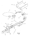
- Figure 1 shows a schematic view in perspective of an automatic cigarette packing machine in accordance with the present invention;
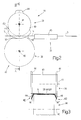
- Figure 2 shows a larger-scale side view of a prefolding station of the automatic machine in Figure 1;
- Figure 3 shows a section along line III-III of the prefolding station in Figure 2;
- Figure 4 shows a front view in perspective of a packet of cigarettes produced on the Figure 1 packing machine and in the closed configuration;
- Figure 5 shows a front view in perspective of the Figure 4 packet in the open configuration;
- Figure 6 shows a rear view in perspective of the Figure 4 packet in the closed configuration;
- Figure 7 shows a plan view of a blank used on the Figure 1 packing machine to produce the Figure 4 packet.
-
-
Number 1 in Figure 1 indicates an automatic packing machine (shown partly and schematically) for producing rigid hinged-lid packets 2 of cigarettes. Eachpacket 2 comprises anorderly group 3 of cigarettes wrapped in a respective sheet of foil wrapping material; acollar 4 aboutgroup 3 and over the sheet of foil wrapping material; and a blank 5 folded aboutgroup 3. -
Packing machine 1 comprises a substantially knownvertical packing wheel 6, in particular of the type featured on the automatic packing machine marketed by G.D. S.p.A. under the trade name "X2".Packing wheel 6 rotates in steps about a horizontal axis 7, and comprises a number ofseats 8 arranged symmetrically along the periphery ofpacking wheel 6. Eachseat 8 is fed cyclically by packingwheel 6 along a circular path and through an input station S1, whereseat 8 is fed with a respective blank 5 and arespective group 3 of cigarettes wrapped in a respective sheet of foil wrapping material and fitted with arespective collar 4; through a series of successive packing stations S2, where blank 5 is gummed and folded aboutgroup 3 of cigarettes to form arespective packet 2; and through an output station S3, where the finishedpacket 2 is fed to a follow-up drying wheel 9. -
Blanks 5 are transferred to input station S1 by astraight conveyor 10, which comprises a series of known fixed rails (not shown) for guidingblanks 5 along a path P; and a number of known transfer rollers (not shown) for pushingblanks 5 along the fixed rails. - Figures 4, 5 and 6 show larger-scale views in perspective of a
packet 2 of cigarettes produced onpacking machine 1 and of the so-called pillow type substantially described in Patent Application WO0043289A1.Packet 2 comprises a cup-shaped bottom container 11 having anopen top end 12; and a cup-shapedtop lid 13 hinged tocontainer 11 along ahinge 14 to rotate, with respect tocontainer 11, between an open position (Figure 5) and a closed position (Figure 4) respectively opening and closingend 12. - In the closed position,
lid 13 imparts to packet 2 a substantially rectangular parallelepiped shape defined by alateral surface 15, and by two facing, respectively top and bottom,end walls lateral surface 15. -
Lateral surface 15 comprises two parallel, facing, flatlateral walls 18; and afront wall 19 andrear wall 20 facing each other and substantially crosswise tolateral walls 18. - Each of front and
rear walls lateral walls 18 along respectivesharp edges 21 perpendicular toend walls lateral walls 18, respective substantially obtuse dihedral angles. - Each of front and
rear walls central portion 22; and twolateral bands 23 located on opposite sides ofcentral portion 22 and betweenportion 22 andcorresponding edges 21. Eachlateral band 23 is precreased internally bylongitudinal crease lines 24, so as to curve with its concavity facing inwards to connect relativecentral portion 22 to the correspondinglateral wall 18 and so form respectivesharp edge 21 and the respective obtuse dihedral angle withlateral wall 18. - Each
end wall lateral edges 25, each of which defines the borderline with a respective majorlateral wall 19 and comprises a substantially straightcentral portion 26 corresponding tocentral portion 22 offront wall 19 orrear wall 20, and two curvedlateral portions 27 corresponding tolateral bands 23 offront wall 19 or rear wall 20 (lateral portions 27 are therefore the same shape as each of respectivelateral bands 23 in cross section). - In a further embodiment not shown, only
front wall 19 orrear wall 20 has an outwardly convex profile, and forms respective substantially obtuse dihedral angles with the twolateral walls 18, while the otherrear wall 20 orfront wall 19 is flat, and forms right-angles with the twolateral walls 18. - In a further embodiment not shown,
front wall 19 andrear wall 20 are flat, while eachlateral wall 18 has an outwardly convex profile and forms respective substantially obtuse dihedral angles withfront wall 19 andrear wall 20. - In a further embodiment not shown,
front wall 19 andrear wall 20 each have a continuously curved outwardly convex profile. That is, as opposed to a flat central portion and two curved lateral bands, as in the Figure 4, 5 and 6 embodiment,front wall 19 andrear wall 20 each have a single, continuously curved surface. -
Packet 2 also comprises arespective collar 4, which is folded into a U and fitted (glued) inside cup-shaped container 11 so as to project partly outwards ofend 12 and engage a corresponding inner surface oflid 13 whenlid 13 is closed (as shown in Figure 1). - As shown in Figure 7,
packet 2 in Figures 1 and 2 is formed from a corresponding flat, substantially elongated rectangular blank 5, the parts of which are indicated, where possible, using the same reference numbers, with superscripts, as for the corresponding parts ofpacket 2. - Blank 5 (which has a central longitudinal axis 28) comprises two
longitudinal crease lines 29; and a number oftransverse crease lines 30 defining, between the twolongitudinal crease lines 29, a panel 19' defining a top portion of front wall 19 (and in particular the portion forming part of lid 13), a panel 16' definingtop end wall 16, a panel 20' definingrear wall 20, a panel 17' definingbottom end wall 17, and apanel 19" defining a bottom portion of front wall 19 (and in particular, the portion forming part of container 11). -
Panels 19', 19" and 20' comprise respective flat central portions 22'; and respective lateral bands 23' located on opposite sides of relative central portions 22' and precreased byrespective crease lines 24. - Each
panel 19', 19", 20' has twolateral wings 18' and 18" located on opposite sides ofpanel 19', 19", 20' and separated frompanel 19', 19", 20' bylongitudinal crease lines 29. Eachwing 18', 18" of panel 20' has trapezoidallongitudinal appendixes 31 located at opposite ends ofwing 18', 18" and aligned longitudinally with each other. - When forming each
packet 2 onpacking wheel 6, each lateral wing 18' and correspondinglateral wing 18" are superimposed and glued together to define a respectivelateral wall 18 ofpacket 2; and eachlongitudinal appendix 31 is folded squarely with respect to the relativelateral wing 18' or 18", and is superimposed on and glued to an inner surface of a relative panel 16' or 17' to define an inner portion of arelative end wall packet 2 respectively. - In a preferred embodiment, longitudinal crease lines 29 (also referred to as main longitudinal crease lines) are weaker than longitudinal crease lines 24 (also referred to as secondary longitudinal crease lines) on account of
longitudinal crease lines 29 defining thesharp edges 21 ofpacket 2, whereaslongitudinal crease lines 24 serve to slightly curve thelateral bands 23 of front andrear walls longitudinal crease lines - As shown in Figure 1,
conveyor 10 feeds blanks 5 successively along straight path P parallel to thelongitudinal axes 28 ofblanks 5. Alongconveyor 10 and upstream from input station S1, a prefolding station S4 is provided comprising twofolding members blanks 5. - Folding
member 32 is located upstream from foldingmember 33, receives each blank 5 in a flat configuration, and foldslateral wings 18' and 18" ofpanels 19' and 19" about respectivelongitudinal crease lines 29, while leavinglateral wings 18' and 18" of panel 20' in the flat configuration. Foldingmember 33 is located downstream from foldingmember 32, receives each blank 5 from foldingmember 32, and, before blank 5 is fed to input station S1, restores blank 5 to the flat configuration by foldinglateral wings 18' and 18" ofpanels 19' and 19" about respectivelongitudinal crease lines 29 in the opposite direction to the folding operation performed byfolding member 32. - In a further embodiment not shown, folding
member 32 foldslateral wings 18' and 18" ofpanels 19', 19" and 20' about respectivelongitudinal crease lines 29 of each blank 5. - In a preferred embodiment, each
seat 8 is defined by aU-shaped folding pocket 34 comprising abottom wall 35 and twolateral walls 36. At input station S1, each blank 5 is inserted insiderespective folding pocket 34, so that panel 20' rests onbottom wall 35, andlateral wings 18' and 18" of panel 20', on contactinglateral walls 36, are folded substantially 90° about respectivelongitudinal crease lines 29 to assume a U-shaped configuration. Theedge 37 betweenbottom wall 35 and eachlateral wall 36 of eachfolding pocket 34 is shaped to negatively reproduce the shape oflateral bands 23 ofrear wall 20 ofpacket 2. At input station S1, each blank 5 is inserted insiderespective folding pocket 34 by a pusher (not shown) shaped to positively reproduce the shape offolding pockets 34 and to engage eachfolding pocket 34 in die-counterdie manner, so that the rear portion of eachpacket 2 is shaped correctly by a stamping process as respective blank 5 is inserted insiderelative folding pocket 34. - As shown in Figures 2 and 3,
folding member 32 comprises twodrums respective axes bottom drum 38 is a contrasting drum, while thetop drum 39 is a folding drum with foldingbodies 42 for foldinglateral wings 18' and 18" about respectivelongitudinal crease lines 29. More specifically,drums panels 19', 20' and 19", while leaving respectivelateral wings 18' and 18" free. For which purpose,contrasting drum 38 is of an axial width substantially equal to (actually slightly less than) the distance betweenlongitudinal crease lines 29; and foldingdrum 39 comprises acentral body 43 of an axial width at least equal to the distance betweenlongitudinal crease lines 29, and which supportslateral appendixes 44 projecting radially and laterally fromcentral body 43 and definingfolding bodies 42. - As shown in Figure 2,
lateral appendixes 44 of foldingdrum 39 comprise physically separate elements for only foldinglateral wings 18' and 18" ofpanels 19' and 19", while leavinglateral wings 18' and 18" of panel 20' in the flat configuration; and the lateral surface of foldingdrum 39 has a circumference substantially equal to the length of a blank 5, so as to work one blank 5 at each turn. - Finally, folding
members 33 comprise two pairs of substantially known fixedhelical folding devices 45 located symmetrically on opposite sides of straight path P to engage and restore to the flat configuration thelateral wings 18' and 18" folded by foldingmember 32. - Tests have shown that prefolding
lateral wings 18' and 18" ofpanels 19' and 19", i.e. the panels definingfront wall 19, of each blank 5, before blank 5 is fed to packingwheel 6, provides for obtaining a high-quality packet 2 in which thelateral bands 23 offront wall 19 are curved correctly and terminate with respective well definedsharp edges 21. - In the case of
rear wall 20, on the other hand, correct curvature oflateral bands 23 and well defined respectivesharp edges 21 are achieved by stamping blank 5, as described above, inside an appropriately shapedrespective folding pocket 34. - Leaving
lateral wings 18' and 18" of panel 20' of each blank 5 in the flat configuration (not foldinglateral wings 18' and 18" at prefolding station S4) ensures greater rigidity of blank 5 in the panel 20' region when blank 5 is fed intorespective folding pocket 34, so that blank 5 is easier to handle and positioned more accurately with respect to foldingpocket 34. - The above method of producing a rigid packet of cigarettes is preferably applied to the manufacture of rigid pillow-type packets, but may be used to advantage for manufacturing any rigid packet of cigarettes having sharp longitudinal edges, by the folding of
lateral wings 18' and 18" at prefolding station S4 ensuring both welldefined edges 21 and a correctly shapedfront wall 19 and/orrear wall 20.
Claims (24)
- A method of producing a substantially parallelepiped-shaped rigid packet of cigarettes comprising a front wall (19) and a rear wall (20) opposite and substantially parallel to each other, and a pair of lateral walls (18) opposite and substantially parallel to each other and substantially perpendicular to the front wall and the rear wall (19, 20); the front wall and the rear wall (19, 20) each being connected to each of the lateral walls (18) at a single respective sharp edge (21); the method comprising the steps of feeding a flat, substantially rectangular blank (5) to a folding station (S2), and folding the blank (5) about an orderly group (3) of cigarettes at the folding station (S2); the blank (5) comprising two main longitudinal crease lines (29), and a number of transverse crease lines (30) defining, between said two main longitudinal crease lines (29), at least a first central panel (19") eventually forming part of said front wall (19), and a second central panel (20') eventually forming said rear wall (20); said two main longitudinal crease lines (29) defining, on opposite sides of each said central panel (19", 20'), at least two respective lateral wings (18', 18") eventually forming part of said lateral walls (18); and the method being characterized by feeding the flat blank (5) to a prefolding station (S4) upstream from said folding station (S2); folding, at said prefolding station (S4), the lateral wings (18', 18") of at least one said central panel (19", 20') about the respective main longitudinal crease lines (29); and restoring the blank (5) to the flat configuration before feeding the blank (5) to said folding station (S2).
- A method as claimed in Claim 1, characterized by folding, at said prefolding station (S4), the lateral wings (18', 18") of at least said first central panel (19") about the respective main longitudinal crease lines (29).
- A method as claimed in Claim 2, characterized in that said transverse crease lines (30) define, between said two main longitudinal crease lines (29), said first central panel (19") eventually forming a bottom portion of said front wall (19), said second central panel (20') eventually forming said rear wall (20), and a third central panel (19') eventually forming a top portion of said front wall (19); said two main longitudinal crease lines (29) defining, on opposite sides of each said central panel (19', 19", 20'), at least two respective lateral wings (18', 18") eventually forming part of said lateral walls (18); at said prefolding station (S4), the lateral wings (18', 18") of at least said first and said third central panel (19", 19') being folded about the respective main longitudinal crease lines (29).
- A method as claimed in Claim 3, characterized by only folding, at said prefolding station (S4), the lateral wings (18', 18") of said first and said third central panel (19', 19") about the respective main longitudinal crease lines (29); the lateral wings (18', 18") of said second central panel (20') being left in the flat configuration at said prefolding station (S4).
- A method as claimed in Claim 3, characterized by folding the lateral wings (18', 18") of said first, said second, and said third central panel (19", 20', 19') about the respective main longitudinal crease lines (29) at said prefolding station (S4).
- A method as claimed in Claim 4 or 5, characterized in that, at said folding station (S2), said flat blank (5) is inserted inside a respective folding pocket (34), in which said second central panel (20') is positioned contacting a bottom wall, and the lateral wings (18', 18") of the second central panel (20') are folded substantially 90° about the respective main longitudinal crease lines (29) to assume a U-shaped configuration.
- A method as claimed in any one of Claims 1 to 6, characterized in that said lateral walls (18) are flat walls, while said front and said rear wall (19, 20) are each outwardly convex, are each connected to each of the two adjacent lateral walls (18) along a respective sharp edge (21), and each form, with the two adjacent lateral walls (18), respective substantially obtuse dihedral angles.
- A method as claimed in Claim 7, characterized in that said front and said rear wall (19, 20) each comprise a respective flat central portion (22), and two lateral bands (23) precreased by further secondary longitudinal crease lines (24), each of which is weakened to a lesser degree than said main longitudinal crease lines (29); each lateral band (23) curving with its concavity facing inwards to connect the relative central portion (22) to the corresponding lateral wall (18), and to form with the lateral wall (18) a respective said substantially obtuse dihedral angle; each said central panel (19', 19", 20') comprising a respective flat central portion (22'), and two respective lateral bands (23') precreased by the further secondary longitudinal crease lines (24).
- A method as claimed in any one of Claims 1 to 6, characterized in that said front and said rear wall (19, 20) are flat walls, while each of said lateral walls (18) is outwardly convex, is connected to each of the two adjacent front and rear walls (19, 20) along a respective sharp edge (21), and forms, with the two adjacent front and rear walls (19, 20), respective substantially obtuse dihedral angles.
- A method as claimed in Claim 9, characterized in that each of said lateral walls (18) comprises a respective flat central portion, and two lateral bands precreased by further secondary longitudinal crease lines, each of which is weakened to a lesser degree than said main longitudinal crease lines (29); each lateral band curving with its concavity facing inwards to connect the relative central portion to the corresponding front or rear wall (19; 20), and to form with the front or rear wall (19; 20) a respective said substantially obtuse dihedral angle.
- A packing machine for producing a substantially parallelepiped-shaped rigid packet of cigarettes comprising a front wall (19) and a rear wall (20) opposite and substantially parallel to each other, and a pair of lateral walls (18) opposite and substantially parallel to each other and substantially perpendicular to the front wall and the rear wall (19, 20); the front wall and the rear wall (19, 20) each being connected to each of the lateral walls (18) at a single respective sharp edge (21); the packing machine (1) comprising a folding station (S2), conveying means (10) for feeding a flat, substantially rectangular blank (5) to the folding station (S2), and first folding devices for folding the blank (5) about an orderly group (3) of cigarettes at the folding station (S2); the blank (5) comprising two main longitudinal crease lines (29), and a number of transverse crease lines (30) defining, between said two main longitudinal crease lines (29), at least a first central panel (19") eventually forming part of said front wall (19), and a second central panel (20') eventually forming said rear wall (20); said two main longitudinal crease lines (29) defining, on opposite sides of each said central panel (19", 20'), at least two respective lateral wings (18', 18") eventually forming part of said lateral walls (18); and the packing machine (1) being characterized by comprising a prefolding station (S4) upstream from said folding station (S2) in the traveling direction of said conveying means (10); second folding devices (32) for folding, at said prefolding station (S4), the lateral wings (18', 18") of at least one said central panel (19", 20') about the respective main longitudinal crease lines (29); and third folding devices (33) for restoring the blank (5) to the flat configuration before feeding the blank (5) to said folding station (S2).
- A machine as claimed in Claim 11, characterized in that, at said prefolding station (S4), said second folding devices (32) fold the lateral wings (18', 18") of at least said first central panel (19") about the respective main longitudinal crease lines (29).
- A machine as claimed in Claim 12, characterized in that said transverse crease lines (30) define, between said two main longitudinal crease lines (29), said first central panel (19") eventually forming a bottom portion of said front wall (19), said second central panel (20') eventually forming said rear wall (20), and a third central panel (19') eventually forming a top portion of said front wall (19); said two main longitudinal crease lines (29) defining, on opposite sides of each said central panel (19', 19", 20'), at least two respective lateral wings (18', 18") eventually forming part of said lateral walls (18); said second folding devices (32) folding the lateral wings (18', 18") of at least said first and said third central panel (19", 19') about the respective main longitudinal crease lines (29).
- A machine as claimed in Claim 13, characterized in that said second folding devices (32) only fold the lateral wings (18', 18") of said first and said third central panel (19', 19") about the respective main longitudinal crease lines (29); the lateral wings (18', 18") of said second central panel (20') being left in the flat configuration at said prefolding station (S4).
- A machine as claimed in any one of Claims 11 to 14, characterized in that said lateral walls (18) are flat walls, while said front and said rear wall (19, 20) are each outwardly convex, are each connected to each of the two adjacent lateral walls (18) along a respective sharp edge (21), and each form, with the two adjacent lateral walls (18), respective substantially obtuse dihedral angles.
- A machine as claimed in Claim 15, characterized in that said front and said rear wall (19, 20) each comprise a respective flat central portion (22), and two lateral bands (23) precreased by further secondary longitudinal crease lines (24), each of which is weakened to a lesser degree than said main longitudinal crease lines (29); each lateral band (23) curving with its concavity facing inwards to connect the relative central portion (22) to the corresponding lateral wall (18), and to form with the lateral wall (18) a respective said substantially obtuse dihedral angle; each said central panel (19', 19", 20') comprising a said respective flat central portion (22'), and two said respective lateral bands (23') precreased by the further secondary longitudinal crease lines (24).
- A machine as claimed in Claim 15 or 16, characterized in that said folding station (S2) comprises a folding pocket (34) for receiving said blank (5) so that said second central panel (20') contacts a bottom wall (35) of the folding pocket (34), and the lateral wings (18', 18") of the second central panel (20') are folded substantially 90° about the respective main longitudinal crease lines (29) to assume a U-shaped configuration.
- A machine as claimed in Claim 17, characterized in that said folding pocket (34) comprises the bottom wall (35) which contacts said second central panel (20'), and a pair of lateral walls (36) which contact said lateral wings (18', 18") of the second central panel (20'); the edge (37) between the bottom wall (35) and each said lateral wall (36) of the folding pocket (34) being shaped to negatively reproduce the shape of said lateral bands of the rear wall (20) of the packet (2).
- A machine as claimed in Claim 18, characterized by comprising a pusher for inserting said blank (5) inside said folding pocket (34), and which is shaped to positively reproduce the shape of the folding pocket (34) and to engage the folding pocket (34) in die-counterdie manner.
- A machine as claimed in any one of Claims 11 to 19, characterized in that said conveying means (10) feed said blank (5) along a straight path (P) parallel to said main longitudinal crease lines (29).
- A machine as claimed in Claim 20, characterized in that said second folding devices (32) comprise two drums (38, 39) which rotate synchronously in opposite directions about respective axes (40, 41) crosswise to said path (P), and between which said blank (5) is fed; one drum (38) being a contrasting drum, and the other drum (39) being a folding drum having folding bodies (42) for folding said lateral wings (18', 18") about the respective main longitudinal crease lines (29).
- A machine as claimed in Claim 21, characterized in that said drums (38, 39) are shaped and sized to successively engage said first, said second, and said third central panel (19", 20', 19'), while leaving said lateral wings (18', 18") free; said folding drum (39) having a central body (43) for engaging the first, second, and third central panel (19", 20', 19'), and lateral appendixes (44) which project radially and laterally from the central body (43), engage and fold the lateral wings (18', 18"), and define said folding bodies (42).
- A machine as claimed in Claim 22, characterized in that said lateral appendixes (44) comprise physically separate elements for only folding the lateral wings (18', 18") of said first and said third central panel (19', 19"), and for maintaining the lateral wings (18', 18") of said second central panel (20') in the flat configuration.
- A machine as claimed in any one of Claims 20 to 23, characterized in that said third folding devices (33) comprise two pairs of fixed helical folding devices (45) located symmetrically on opposite sides of said straight path (P).
Applications Claiming Priority (2)
| Application Number | Priority Date | Filing Date | Title |
|---|---|---|---|
| ITBO20010553 | 2001-09-14 | ||
| IT2001BO000553A ITBO20010553A1 (en) | 2001-09-14 | 2001-09-14 | METHOD AND MACHINE FOR THE PRODUCTION OF A RIGID CIGARETTE PACKAGE |
Publications (2)
| Publication Number | Publication Date |
|---|---|
| EP1293431A1 true EP1293431A1 (en) | 2003-03-19 |
| EP1293431B1 EP1293431B1 (en) | 2006-07-12 |
Family
ID=11439598
Family Applications (1)
| Application Number | Title | Priority Date | Filing Date |
|---|---|---|---|
| EP02020386A Expired - Lifetime EP1293431B1 (en) | 2001-09-14 | 2002-09-12 | Method and machine for producing a rigid packet of cigarettes |
Country Status (7)
| Country | Link |
|---|---|
| US (1) | US6694708B2 (en) |
| EP (1) | EP1293431B1 (en) |
| JP (1) | JP4047677B2 (en) |
| CN (1) | CN1230355C (en) |
| AT (1) | ATE332841T1 (en) |
| DE (1) | DE60213049T2 (en) |
| IT (1) | ITBO20010553A1 (en) |
Cited By (3)
| Publication number | Priority date | Publication date | Assignee | Title |
|---|---|---|---|---|
| EP1396430A3 (en) * | 2002-09-06 | 2005-09-21 | Focke & Co. (GmbH & Co. KG) | Procedure for the production of hinged lid boxes |
| ITBO20130427A1 (en) * | 2013-08-01 | 2015-02-02 | Gd Spa | MACHINE AND PACKAGING METHOD OF CIGARETTE PACKAGES. |
| EP3599088A3 (en) * | 2018-07-25 | 2020-07-29 | Focke & Co. (GmbH & Co. KG) | Method and device for handling blanks made of packaging material |
Families Citing this family (26)
| Publication number | Priority date | Publication date | Assignee | Title |
|---|---|---|---|---|
| ITBO20030576A1 (en) * | 2003-10-08 | 2005-04-09 | Gd Spa | METHOD AND UNIT FOR RESTING A BLOCKED FLOOR INTENDED FOR THE REALIZATION OF A RIGID WRAP |
| ITBO20030671A1 (en) * | 2003-11-13 | 2005-05-14 | Gd Spa | METHOD AND DEVICE FOR THE REALIZATION OF A CONTAINER |
| ITBO20040434A1 (en) * | 2004-07-12 | 2004-10-12 | Gd Spa | METHOD FOR THE FORMATION OF A HINGED LID PORTFOLIO PACKAGE |
| EP1645510A1 (en) * | 2004-10-07 | 2006-04-12 | Philip Morris Products S.A. | Method and apparatus for making hinge-lid packs of cigarettes |
| ITBO20050235A1 (en) * | 2005-04-13 | 2005-07-13 | Gd Spa | CIGARETTE PACKAGING MACHINE FOR THE CREATION OF RIGID PACKAGES WITH HINGED LID |
| ITBO20060588A1 (en) * | 2006-08-03 | 2008-02-04 | Gd Spa | METHOD AND UNIT FOR BENDING A REINFORCEMENT PAD OF THE LID OF A RIGID CIGARETTE PACKAGE WITH HINGED LID. |
| US7762046B2 (en) * | 2008-04-11 | 2010-07-27 | R.J. Reynolds Tobacco Company | Method for manufacturing cigarette packages |
| IT1394943B1 (en) | 2009-04-17 | 2012-07-27 | Gima Spa | DEVICE FOR PACKAGING A PRODUCT IN A CORRESPONDENT CONTAINER |
| US8118161B2 (en) | 2009-08-20 | 2012-02-21 | R.J. Reynolds Tobacco Company | Pressurized cigarette packages and methods |
| US8046978B2 (en) | 2009-10-02 | 2011-11-01 | R.J. Reynolds Tobacco Company | Equipment and method for packaging multiple packets of cigarettes |
| EP2521646A1 (en) * | 2010-01-07 | 2012-11-14 | Mohrbach Verpackungsmaschinen GmbH | Method and device for producing boxes from paper or cardboard |
| KR101288807B1 (en) * | 2011-04-28 | 2013-07-23 | 주식회사 케이티앤지 | Apparatus and method for manufacturing cigarette case |
| ITBO20120032A1 (en) * | 2012-01-26 | 2013-07-27 | Gd Spa | WRAPPING MACHINE AND WRAPPING METHOD TO PRODUCE A PACKAGE OF SLIDING SMOKE ITEMS. |
| ITBO20120031A1 (en) * | 2012-01-26 | 2012-04-26 | Gd Spa | WRAPPING MACHINE AND WRAPPING METHOD TO CREATE A PACKAGE OF SMOKE ITEMS WITH SLIDING OPENING AND WITH HINGED AND BOILED LID. |
| US10315376B2 (en) * | 2012-11-08 | 2019-06-11 | The C.W. Zumbiel Company | System and associated method for digital scoring of carton blanks |
| US20140141952A1 (en) * | 2012-11-20 | 2014-05-22 | Rock-Tenn Shared Services, Llc | Methods and apparatus for forming a reinforced tray |
| ITBO20120659A1 (en) * | 2012-12-05 | 2014-06-06 | Sasib Spa | BLOCKED FOR COVERED PACKAGES FOR SMOKE ITEMS AND METHOD FOR THE REALIZATION OF SUCH PACKAGES |
| ITBO20130018A1 (en) * | 2013-01-18 | 2014-07-19 | Gd Spa | WRAPPING MACHINE AND SETTING METHOD TO REALIZE A RIGID PACKAGE OF SMOKE ITEMS. |
| DE102013009471A1 (en) * | 2013-06-06 | 2014-12-11 | Focke & Co. (Gmbh & Co. Kg) | Method and device for producing (cigarette) packages |
| CN103350793B (en) * | 2013-07-16 | 2014-12-17 | 王前宏 | Carton folding device of full-automatic carton lifting handle eyeleting machine |
| CN103538291B (en) * | 2013-10-21 | 2016-01-06 | 深圳九星印刷包装集团有限公司 | Double folding inner supporting screen cartridge binds accessory assembly |
| US10063814B2 (en) | 2014-03-12 | 2018-08-28 | R.J. Reynolds Tobacco Company | Smoking article package inspection system and associated method |
| WO2016031010A1 (en) * | 2014-08-28 | 2016-03-03 | 日本たばこ産業株式会社 | Blank-supplying apparatus, method for supplying blank using same |
| PL231147B1 (en) * | 2016-04-12 | 2019-01-31 | Piotr Garmulewicz | Device for forming packages and method for forming packages |
| CN106626514B (en) * | 2016-11-25 | 2019-03-05 | 广东至远实业集团有限公司 | A kind of cigarette case package automatic edge sealing mechanism and edge bonding method |
| IT201800006711A1 (en) * | 2018-06-27 | 2019-12-27 | Drawer designed to hold a group of smoking articles and a collar, method of feeding a group of smoking articles and a collar to the drawer, and a packaging machine for smoking articles equipped with a wrapping conveyor equipped with the drawer |
Citations (4)
| Publication number | Priority date | Publication date | Assignee | Title |
|---|---|---|---|---|
| GB838385A (en) * | 1958-08-14 | 1960-06-22 | Liesbeth Schwarz | Improvements in shoulder box machinery |
| DE3522614A1 (en) * | 1985-06-25 | 1987-01-15 | Focke & Co | METHOD AND DEVICE FOR PRODUCING PACKINGS WITH BEEPED OR ROUNDED EDGES |
| EP0900646A1 (en) * | 1997-09-04 | 1999-03-10 | G.D Societa' Per Azioni | Method of folding packing blanks |
| DE10047447A1 (en) * | 1999-09-21 | 2001-05-17 | Gd Spa | Blank for producing a rigid cigarette package has precreased fold lines, one set of which has degree of weakening which is greater than that of second set |
Family Cites Families (5)
| Publication number | Priority date | Publication date | Assignee | Title |
|---|---|---|---|---|
| US2054833A (en) * | 1933-09-06 | 1936-09-22 | Potdevin Machine Co | Apparatus for making bags |
| US2785609A (en) * | 1953-07-03 | 1957-03-19 | Milprint Inc | Art of producing lip-type bags |
| US3398660A (en) * | 1966-09-20 | 1968-08-27 | Procter & Gamble | Machine for making frame blanks and for thereafter forming said blanks around an article |
| US4273550A (en) * | 1978-03-24 | 1981-06-16 | Union Carbide Corporation | Method for producing a flat bottom plastic bag |
| IT1306254B1 (en) * | 1995-05-05 | 2001-06-04 | Gd Spa | METHOD AND MACHINE FOR PACKAGING PRODUCTS |
-
2001
- 2001-09-14 IT IT2001BO000553A patent/ITBO20010553A1/en unknown
-
2002
- 2002-09-10 US US10/238,334 patent/US6694708B2/en not_active Expired - Fee Related
- 2002-09-12 EP EP02020386A patent/EP1293431B1/en not_active Expired - Lifetime
- 2002-09-12 DE DE60213049T patent/DE60213049T2/en not_active Expired - Lifetime
- 2002-09-12 AT AT02020386T patent/ATE332841T1/en not_active IP Right Cessation
- 2002-09-13 JP JP2002268423A patent/JP4047677B2/en not_active Expired - Fee Related
- 2002-09-16 CN CNB021429391A patent/CN1230355C/en not_active Expired - Fee Related
Patent Citations (4)
| Publication number | Priority date | Publication date | Assignee | Title |
|---|---|---|---|---|
| GB838385A (en) * | 1958-08-14 | 1960-06-22 | Liesbeth Schwarz | Improvements in shoulder box machinery |
| DE3522614A1 (en) * | 1985-06-25 | 1987-01-15 | Focke & Co | METHOD AND DEVICE FOR PRODUCING PACKINGS WITH BEEPED OR ROUNDED EDGES |
| EP0900646A1 (en) * | 1997-09-04 | 1999-03-10 | G.D Societa' Per Azioni | Method of folding packing blanks |
| DE10047447A1 (en) * | 1999-09-21 | 2001-05-17 | Gd Spa | Blank for producing a rigid cigarette package has precreased fold lines, one set of which has degree of weakening which is greater than that of second set |
Cited By (4)
| Publication number | Priority date | Publication date | Assignee | Title |
|---|---|---|---|---|
| EP1396430A3 (en) * | 2002-09-06 | 2005-09-21 | Focke & Co. (GmbH & Co. KG) | Procedure for the production of hinged lid boxes |
| ITBO20130427A1 (en) * | 2013-08-01 | 2015-02-02 | Gd Spa | MACHINE AND PACKAGING METHOD OF CIGARETTE PACKAGES. |
| WO2015015409A1 (en) * | 2013-08-01 | 2015-02-05 | G. D S.P.A. | Packaging machine and method for packing cigarettes. |
| EP3599088A3 (en) * | 2018-07-25 | 2020-07-29 | Focke & Co. (GmbH & Co. KG) | Method and device for handling blanks made of packaging material |
Also Published As
| Publication number | Publication date |
|---|---|
| EP1293431B1 (en) | 2006-07-12 |
| CN1408616A (en) | 2003-04-09 |
| US6694708B2 (en) | 2004-02-24 |
| CN1230355C (en) | 2005-12-07 |
| DE60213049D1 (en) | 2006-08-24 |
| JP4047677B2 (en) | 2008-02-13 |
| DE60213049T2 (en) | 2007-01-11 |
| US20030093977A1 (en) | 2003-05-22 |
| ITBO20010553A1 (en) | 2003-03-14 |
| ITBO20010553A0 (en) | 2001-09-14 |
| JP2003104317A (en) | 2003-04-09 |
| ATE332841T1 (en) | 2006-08-15 |
Similar Documents
| Publication | Publication Date | Title |
|---|---|---|
| US6694708B2 (en) | Method and machine for producing a rigid packet of cigarettes | |
| US7155882B2 (en) | Method of producing a hinged-lid wallet packet | |
| EP1712470B1 (en) | Cigarette packing machine for producing rigid hinged-lid packets | |
| US20010007187A1 (en) | Process and apparatus for producing (cigarette) packs | |
| US6439239B1 (en) | Method for forming a packet of cigarettes | |
| EP2740682B1 (en) | Method for making hinged-lid packets for smoking articles | |
| EP1463675B1 (en) | Rigid container for tobacco articles | |
| GB2297956A (en) | Blank gumming method for cigarette packaging machines | |
| RU2672343C2 (en) | Device for supplying blanks and method for supplying blanks therewith | |
| EP1145958B1 (en) | Method and machine for producing hinged-lid packets of cigarettes | |
| US5822948A (en) | Product manipulating method | |
| EP1854724B1 (en) | Method and packing machine for producing packets of cigarettes | |
| EP0900646A1 (en) | Method of folding packing blanks | |
| CN109421314B (en) | Method and device for producing cigarette packs | |
| US5822954A (en) | Method and unit for folding packing blanks along preformed bend lines | |
| KR101644326B1 (en) | Packing method and unit for folding a sheet of packing material about an article, such as a group of cigarettes | |
| CN100537210C (en) | Method and device for bending flat blanks for the production of rigid packaging | |
| GB2452322A (en) | Method and packing machine for folding a collar and blank about a group of cigarettes | |
| US20040144621A1 (en) | Method and conveyor for conveying articles | |
| PL213101B1 (en) | The manner and packing machine for folding of a flange and a die around a group of cigarettes and machine for packing of cigarettes |
Legal Events
| Date | Code | Title | Description |
|---|---|---|---|
| PUAI | Public reference made under article 153(3) epc to a published international application that has entered the european phase |
Free format text: ORIGINAL CODE: 0009012 |
|
| AK | Designated contracting states |
Kind code of ref document: A1 Designated state(s): AT BE BG CH CY CZ DE DK EE ES FI FR GB GR IE IT LI LU MC NL PT SE SK TR |
|
| AX | Request for extension of the european patent |
Extension state: AL LT LV MK RO SI |
|
| 17P | Request for examination filed |
Effective date: 20030912 |
|
| AKX | Designation fees paid |
Designated state(s): AT BE BG CH CY CZ DE DK EE ES FI FR GB GR IE IT LI LU MC NL PT SE SK TR |
|
| 17Q | First examination report despatched |
Effective date: 20031128 |
|
| GRAP | Despatch of communication of intention to grant a patent |
Free format text: ORIGINAL CODE: EPIDOSNIGR1 |
|
| GRAS | Grant fee paid |
Free format text: ORIGINAL CODE: EPIDOSNIGR3 |
|
| GRAA | (expected) grant |
Free format text: ORIGINAL CODE: 0009210 |
|
| AK | Designated contracting states |
Kind code of ref document: B1 Designated state(s): AT BE BG CH CY CZ DE DK EE ES FI FR GB GR IE IT LI LU MC NL PT SE SK TR |
|
| PG25 | Lapsed in a contracting state [announced via postgrant information from national office to epo] |
Ref country code: IT Free format text: LAPSE BECAUSE OF FAILURE TO SUBMIT A TRANSLATION OF THE DESCRIPTION OR TO PAY THE FEE WITHIN THE PRESCRIBED TIME-LIMIT;WARNING: LAPSES OF ITALIAN PATENTS WITH EFFECTIVE DATE BEFORE 2007 MAY HAVE OCCURRED AT ANY TIME BEFORE 2007. THE CORRECT EFFECTIVE DATE MAY BE DIFFERENT FROM THE ONE RECORDED. Effective date: 20060712 Ref country code: BE Free format text: LAPSE BECAUSE OF FAILURE TO SUBMIT A TRANSLATION OF THE DESCRIPTION OR TO PAY THE FEE WITHIN THE PRESCRIBED TIME-LIMIT Effective date: 20060712 Ref country code: AT Free format text: LAPSE BECAUSE OF FAILURE TO SUBMIT A TRANSLATION OF THE DESCRIPTION OR TO PAY THE FEE WITHIN THE PRESCRIBED TIME-LIMIT Effective date: 20060712 Ref country code: CZ Free format text: LAPSE BECAUSE OF FAILURE TO SUBMIT A TRANSLATION OF THE DESCRIPTION OR TO PAY THE FEE WITHIN THE PRESCRIBED TIME-LIMIT Effective date: 20060712 Ref country code: NL Free format text: LAPSE BECAUSE OF FAILURE TO SUBMIT A TRANSLATION OF THE DESCRIPTION OR TO PAY THE FEE WITHIN THE PRESCRIBED TIME-LIMIT Effective date: 20060712 Ref country code: FI Free format text: LAPSE BECAUSE OF FAILURE TO SUBMIT A TRANSLATION OF THE DESCRIPTION OR TO PAY THE FEE WITHIN THE PRESCRIBED TIME-LIMIT Effective date: 20060712 Ref country code: SK Free format text: LAPSE BECAUSE OF FAILURE TO SUBMIT A TRANSLATION OF THE DESCRIPTION OR TO PAY THE FEE WITHIN THE PRESCRIBED TIME-LIMIT Effective date: 20060712 |
|
| REG | Reference to a national code |
Ref country code: GB Ref legal event code: FG4D |
|
| REG | Reference to a national code |
Ref country code: CH Ref legal event code: EP |
|
| REG | Reference to a national code |
Ref country code: IE Ref legal event code: FG4D |
|
| REF | Corresponds to: |
Ref document number: 60213049 Country of ref document: DE Date of ref document: 20060824 Kind code of ref document: P |
|
| REG | Reference to a national code |
Ref country code: CH Ref legal event code: NV Representative=s name: BOVARD AG PATENTANWAELTE |
|
| PG25 | Lapsed in a contracting state [announced via postgrant information from national office to epo] |
Ref country code: IE Free format text: LAPSE BECAUSE OF NON-PAYMENT OF DUE FEES Effective date: 20060912 |
|
| PGFP | Annual fee paid to national office [announced via postgrant information from national office to epo] |
Ref country code: FR Payment date: 20060918 Year of fee payment: 5 |
|
| PG25 | Lapsed in a contracting state [announced via postgrant information from national office to epo] |
Ref country code: MC Free format text: LAPSE BECAUSE OF NON-PAYMENT OF DUE FEES Effective date: 20060930 |
|
| PG25 | Lapsed in a contracting state [announced via postgrant information from national office to epo] |
Ref country code: DK Free format text: LAPSE BECAUSE OF FAILURE TO SUBMIT A TRANSLATION OF THE DESCRIPTION OR TO PAY THE FEE WITHIN THE PRESCRIBED TIME-LIMIT Effective date: 20061012 Ref country code: SE Free format text: LAPSE BECAUSE OF FAILURE TO SUBMIT A TRANSLATION OF THE DESCRIPTION OR TO PAY THE FEE WITHIN THE PRESCRIBED TIME-LIMIT Effective date: 20061012 Ref country code: BG Free format text: LAPSE BECAUSE OF FAILURE TO SUBMIT A TRANSLATION OF THE DESCRIPTION OR TO PAY THE FEE WITHIN THE PRESCRIBED TIME-LIMIT Effective date: 20061012 |
|
| PG25 | Lapsed in a contracting state [announced via postgrant information from national office to epo] |
Ref country code: ES Free format text: LAPSE BECAUSE OF FAILURE TO SUBMIT A TRANSLATION OF THE DESCRIPTION OR TO PAY THE FEE WITHIN THE PRESCRIBED TIME-LIMIT Effective date: 20061023 |
|
| PG25 | Lapsed in a contracting state [announced via postgrant information from national office to epo] |
Ref country code: PT Free format text: LAPSE BECAUSE OF FAILURE TO SUBMIT A TRANSLATION OF THE DESCRIPTION OR TO PAY THE FEE WITHIN THE PRESCRIBED TIME-LIMIT Effective date: 20061212 |
|
| NLV1 | Nl: lapsed or annulled due to failure to fulfill the requirements of art. 29p and 29m of the patents act | ||
| ET | Fr: translation filed | ||
| PLBE | No opposition filed within time limit |
Free format text: ORIGINAL CODE: 0009261 |
|
| STAA | Information on the status of an ep patent application or granted ep patent |
Free format text: STATUS: NO OPPOSITION FILED WITHIN TIME LIMIT |
|
| 26N | No opposition filed |
Effective date: 20070413 |
|
| PG25 | Lapsed in a contracting state [announced via postgrant information from national office to epo] |
Ref country code: GR Free format text: LAPSE BECAUSE OF FAILURE TO SUBMIT A TRANSLATION OF THE DESCRIPTION OR TO PAY THE FEE WITHIN THE PRESCRIBED TIME-LIMIT Effective date: 20061013 |
|
| PG25 | Lapsed in a contracting state [announced via postgrant information from national office to epo] |
Ref country code: EE Free format text: LAPSE BECAUSE OF FAILURE TO SUBMIT A TRANSLATION OF THE DESCRIPTION OR TO PAY THE FEE WITHIN THE PRESCRIBED TIME-LIMIT Effective date: 20060712 |
|
| PG25 | Lapsed in a contracting state [announced via postgrant information from national office to epo] |
Ref country code: TR Free format text: LAPSE BECAUSE OF FAILURE TO SUBMIT A TRANSLATION OF THE DESCRIPTION OR TO PAY THE FEE WITHIN THE PRESCRIBED TIME-LIMIT Effective date: 20060712 Ref country code: LU Free format text: LAPSE BECAUSE OF NON-PAYMENT OF DUE FEES Effective date: 20060912 |
|
| REG | Reference to a national code |
Ref country code: FR Ref legal event code: ST Effective date: 20080531 |
|
| PG25 | Lapsed in a contracting state [announced via postgrant information from national office to epo] |
Ref country code: FR Free format text: LAPSE BECAUSE OF NON-PAYMENT OF DUE FEES Effective date: 20071001 |
|
| PG25 | Lapsed in a contracting state [announced via postgrant information from national office to epo] |
Ref country code: CY Free format text: LAPSE BECAUSE OF FAILURE TO SUBMIT A TRANSLATION OF THE DESCRIPTION OR TO PAY THE FEE WITHIN THE PRESCRIBED TIME-LIMIT Effective date: 20060712 |
|
| PGFP | Annual fee paid to national office [announced via postgrant information from national office to epo] |
Ref country code: CH Payment date: 20100930 Year of fee payment: 9 |
|
| REG | Reference to a national code |
Ref country code: CH Ref legal event code: PFA Owner name: G.D SOCIETA PER AZIONI Free format text: G.D SOCIETA PER AZIONI#VIA BATTINDARNO, 91#40133 BOLOGNA (BO) (IT) -TRANSFER TO- G.D SOCIETA PER AZIONI#VIA BATTINDARNO, 91#40133 BOLOGNA (BO) (IT) |
|
| REG | Reference to a national code |
Ref country code: CH Ref legal event code: PL |
|
| PG25 | Lapsed in a contracting state [announced via postgrant information from national office to epo] |
Ref country code: CH Free format text: LAPSE BECAUSE OF NON-PAYMENT OF DUE FEES Effective date: 20110930 Ref country code: LI Free format text: LAPSE BECAUSE OF NON-PAYMENT OF DUE FEES Effective date: 20110930 |
|
| PGFP | Annual fee paid to national office [announced via postgrant information from national office to epo] |
Ref country code: GB Payment date: 20150928 Year of fee payment: 14 |
|
| PGFP | Annual fee paid to national office [announced via postgrant information from national office to epo] |
Ref country code: DE Payment date: 20150929 Year of fee payment: 14 |
|
| REG | Reference to a national code |
Ref country code: DE Ref legal event code: R119 Ref document number: 60213049 Country of ref document: DE |
|
| GBPC | Gb: european patent ceased through non-payment of renewal fee |
Effective date: 20160912 |
|
| PG25 | Lapsed in a contracting state [announced via postgrant information from national office to epo] |
Ref country code: GB Free format text: LAPSE BECAUSE OF NON-PAYMENT OF DUE FEES Effective date: 20160912 Ref country code: DE Free format text: LAPSE BECAUSE OF NON-PAYMENT OF DUE FEES Effective date: 20170401 |