EP1292383B1 - Tubular reactor for carrying out exothermic gas phase reactions - Google Patents
Tubular reactor for carrying out exothermic gas phase reactions Download PDFInfo
- Publication number
- EP1292383B1 EP1292383B1 EP01933928A EP01933928A EP1292383B1 EP 1292383 B1 EP1292383 B1 EP 1292383B1 EP 01933928 A EP01933928 A EP 01933928A EP 01933928 A EP01933928 A EP 01933928A EP 1292383 B1 EP1292383 B1 EP 1292383B1
- Authority
- EP
- European Patent Office
- Prior art keywords
- gas supply
- gas
- tubular reactor
- reaction
- tubes
- Prior art date
- Legal status (The legal status is an assumption and is not a legal conclusion. Google has not performed a legal analysis and makes no representation as to the accuracy of the status listed.)
- Expired - Lifetime
Links
Images


Classifications
-
- B—PERFORMING OPERATIONS; TRANSPORTING
- B01—PHYSICAL OR CHEMICAL PROCESSES OR APPARATUS IN GENERAL
- B01J—CHEMICAL OR PHYSICAL PROCESSES, e.g. CATALYSIS OR COLLOID CHEMISTRY; THEIR RELEVANT APPARATUS
- B01J8/00—Chemical or physical processes in general, conducted in the presence of fluids and solid particles; Apparatus for such processes
- B01J8/02—Chemical or physical processes in general, conducted in the presence of fluids and solid particles; Apparatus for such processes with stationary particles, e.g. in fixed beds
- B01J8/06—Chemical or physical processes in general, conducted in the presence of fluids and solid particles; Apparatus for such processes with stationary particles, e.g. in fixed beds in tube reactors; the solid particles being arranged in tubes
- B01J8/065—Feeding reactive fluids
-
- C—CHEMISTRY; METALLURGY
- C07—ORGANIC CHEMISTRY
- C07C—ACYCLIC OR CARBOCYCLIC COMPOUNDS
- C07C45/00—Preparation of compounds having >C = O groups bound only to carbon or hydrogen atoms; Preparation of chelates of such compounds
- C07C45/27—Preparation of compounds having >C = O groups bound only to carbon or hydrogen atoms; Preparation of chelates of such compounds by oxidation
- C07C45/32—Preparation of compounds having >C = O groups bound only to carbon or hydrogen atoms; Preparation of chelates of such compounds by oxidation with molecular oxygen
- C07C45/33—Preparation of compounds having >C = O groups bound only to carbon or hydrogen atoms; Preparation of chelates of such compounds by oxidation with molecular oxygen of CHx-moieties
- C07C45/34—Preparation of compounds having >C = O groups bound only to carbon or hydrogen atoms; Preparation of chelates of such compounds by oxidation with molecular oxygen of CHx-moieties in unsaturated compounds
- C07C45/35—Preparation of compounds having >C = O groups bound only to carbon or hydrogen atoms; Preparation of chelates of such compounds by oxidation with molecular oxygen of CHx-moieties in unsaturated compounds in propene or isobutene
-
- B—PERFORMING OPERATIONS; TRANSPORTING
- B01—PHYSICAL OR CHEMICAL PROCESSES OR APPARATUS IN GENERAL
- B01J—CHEMICAL OR PHYSICAL PROCESSES, e.g. CATALYSIS OR COLLOID CHEMISTRY; THEIR RELEVANT APPARATUS
- B01J2208/00—Processes carried out in the presence of solid particles; Reactors therefor
- B01J2208/00008—Controlling the process
- B01J2208/00017—Controlling the temperature
- B01J2208/00106—Controlling the temperature by indirect heat exchange
- B01J2208/00168—Controlling the temperature by indirect heat exchange with heat exchange elements outside the bed of solid particles
- B01J2208/00212—Plates; Jackets; Cylinders
-
- B—PERFORMING OPERATIONS; TRANSPORTING
- B01—PHYSICAL OR CHEMICAL PROCESSES OR APPARATUS IN GENERAL
- B01J—CHEMICAL OR PHYSICAL PROCESSES, e.g. CATALYSIS OR COLLOID CHEMISTRY; THEIR RELEVANT APPARATUS
- B01J2208/00—Processes carried out in the presence of solid particles; Reactors therefor
- B01J2208/00008—Controlling the process
- B01J2208/00017—Controlling the temperature
- B01J2208/00106—Controlling the temperature by indirect heat exchange
- B01J2208/00168—Controlling the temperature by indirect heat exchange with heat exchange elements outside the bed of solid particles
- B01J2208/00256—Controlling the temperature by indirect heat exchange with heat exchange elements outside the bed of solid particles in a heat exchanger for the heat exchange medium separate from the reactor
-
- B—PERFORMING OPERATIONS; TRANSPORTING
- B01—PHYSICAL OR CHEMICAL PROCESSES OR APPARATUS IN GENERAL
- B01J—CHEMICAL OR PHYSICAL PROCESSES, e.g. CATALYSIS OR COLLOID CHEMISTRY; THEIR RELEVANT APPARATUS
- B01J2219/00—Chemical, physical or physico-chemical processes in general; Their relevant apparatus
- B01J2219/00049—Controlling or regulating processes
- B01J2219/00245—Avoiding undesirable reactions or side-effects
- B01J2219/00259—Preventing runaway of the chemical reaction
- B01J2219/00263—Preventing explosion of the chemical mixture
Definitions
- the invention relates to a tubular reactor according to the generic term of claim 1.
- a mixing nozzle 64 here in the form of a Venturi tube recognize while at the inlet end of the gas supply pipe a throttle body 66 is located to gas admission also to meter the gas outlet from the gas supply pipe 34. If necessary, this dosage is also radial Pressure drop within the gas supply chamber 30 to bill wear.
- the mixing nozzle 64 should be as quick and effective as possible Cause admixture of the second to the first reactant. Under certain circumstances you can also on the gas supply pipe (34) several such mixing nozzles can be provided.
- the steam produced is separated from the liquid in a separator 136 Phase separated and used for another purpose, while the liquid heat carrier is returned to the circuit becomes.
- a separator 136 Phase separated and used for another purpose, while the liquid heat carrier is returned to the circuit becomes.
- that is called steam dissipated heat transfer is constantly replaced.
- the cycles are there for that of reactor sections 132 and 134 at 140 with each other Connection.
- 142 is a cooler and 144 is a pump in the circuit of section 132.
Landscapes
- Chemical & Material Sciences (AREA)
- Organic Chemistry (AREA)
- Chemical Kinetics & Catalysis (AREA)
- Devices And Processes Conducted In The Presence Of Fluids And Solid Particles (AREA)
- Organic Low-Molecular-Weight Compounds And Preparation Thereof (AREA)
- Physical Or Chemical Processes And Apparatus (AREA)
Abstract
Description
Die Erfindung betrifft einen Röhrenreaktor gemäß Gattungsbegriff des Patentanspruchs 1.The invention relates to a tubular reactor according to the generic term of claim 1.
Röhrenreaktoren finden für vielerlei chemische Reaktionsprozesse Verwendung, unter anderem die katalytische Oxidation von Kohlenwasserstoffen wie zum Beispiel zur Herstellung von Ethylenoxid oder von Essigsäure. Dabei erfolgt die Umsetzung beispielsweise im Kreislaufverfahren, wobei vor Eintritt in den Reaktor laufend frisches Reaktionsgas zugesetzt und nach dem Austritt aus dem Reaktor die abzuführenden Stoffströme abgetrennt werden. Die Ausbeute pro Durchgang und damit auch die Größe des Reaktors samt zugehöriger Aggregate wie Pumpen, Gebläse und dergl. sowie die dafür erforderliche Antriebsleistung hängen wesentlich von der Effizienz der Umsetzung und diese wiederum von dem Mischungsverhältnis der Reaktanten ab. Dieses findet indessen Grenzen in der Beherrschbarkeit der anfallenden Reaktionswärmemenge und in manchen Fällen auch in einem Abbrand- oder sogar Explosionsrisiko. So ist man dabei herkömmlicherweise etwa gezwungen, den O2-Anteil am Eintritt des Reaktors auf wenige Prozent zu begrenzen. Ähnliche Probleme bestehen beispielsweise bei der Herstellung von Phthalsäureanhydrid, Maleinsäureanhydrid, Acrolein und Acrylsäure.Tube reactors are used for a wide range of chemical reaction processes, including the catalytic oxidation of hydrocarbons such as those used to produce ethylene oxide or acetic acid. The reaction is carried out, for example, in a recycle process, with fresh reaction gas being added continuously before entry into the reactor and the material streams to be removed being separated off after leaving the reactor. The yield per run and thus also the size of the reactor including the associated units such as pumps, blowers and the like, as well as the drive power required for this depend essentially on the efficiency of the reaction and this in turn on the mixing ratio of the reactants. However, this finds limits in the controllability of the heat of reaction and in some cases also in a risk of burning or even explosion. For example, one is usually forced to limit the O 2 content at the inlet of the reactor to a few percent. Similar problems exist, for example, in the production of phthalic anhydride, maleic anhydride, acrolein and acrylic acid.
Durch mancherlei Maßnahmen ist es bereits gelungen, die Beladung des Reaktionsgasgemisches mit einer kritischen Komponente, wie z.B. O2, dadurch zu steigern, daß man die sich entlang den Kontaktrohren einstellende Temperatur in gewünschter Weise über den Wärmeträgerkreislauf steuert. Maßnahmen hierfür sind etwa DE-C-2 201 528 zu entnehmen, wonach der Reaktor in mehrere aufeinanderfolgende Abschnitte mit mehr oder weniger separaten Wärmeträgerkreisläufen und ggf. auch unterschiedlichen Katalysatorfüllungen unterteilt sein kann und dazu noch verschiedenartige Umlenk- und/oder Verteilerplatten Verwendung finden können. Des weiteren wurde bereits vorgeschlagen, zumindest einen Anteil der kritischen Komponente erst nach und nach im Zuge des Reaktionsablaufes zuzuführen, so z.B. mittels durch die Reaktionsrohre hindurchlaufender separater Gaszuführungsrohre mit verstreuten oder auch diskreten aufeinanderfolgenden Gasaustrittsstellen (Tonkovich et al. "Inorganic Membrane Reactors for the Oxidative Coupling of Ethane", Chem. Engineering Science, Vol. 51, No. 11, 1996, S. 3051 - 3056, bzw. US-A-5,723,094). Derartige Gaszuführungsrohre sind freilich, vor allem in industriellem Umfang, nur schwer zu verwirklichen, nicht zuletzt was eine wünschenswerte Verteilung des Gasaustritts über die Rohrlänge angeht, aber auch hinsichtlich der Gaszuführung zu einer Vielzahl solcher Gaszuführungsrohre, die bei einem industriellen Röhrenreaktor etwa 10.000 oder mehr betragen kann.Various measures have already succeeded in increasing the loading of the reaction gas mixture with a critical component, such as O 2 , in that the temperature which is established along the contact tubes is controlled in the desired manner via the heat transfer circuit. Measures for this can be found, for example, in DE-C-2 201 528, according to which the reactor can be divided into several successive sections with more or less separate heat transfer circuits and possibly also different catalyst fillings, and various types of deflection and / or distributor plates can also be used. Furthermore, it has already been suggested that at least a portion of the critical component be added little by little in the course of the course of the reaction, for example by means of separate gas supply tubes with scattered or discrete successive gas outlet points running through the reaction tubes (Tonkovich et al. "Inorganic Membrane Reactors for the Oxidative Coupling of Ethane ", Chem. Engineering Science, Vol. 51, No. 11, 1996, pp. 3051-3056, or US-A-5,723,094). Such gas supply pipes are of course difficult to implement, especially on an industrial scale, not least with regard to a desirable distribution of the gas outlet over the pipe length, but also with regard to the gas supply to a large number of such gas supply pipes, which are around 10,000 or more in an industrial tubular reactor can.
Aus US-A-3,518,284 - wovon im Gattungsbegriff des Patentanspruchs 1 ausgegangen wird - ist des weiteren die Zuführung eines zweiten Reaktanten durch lediglich in das gaseintrittsseitige Ende der Reaktionsrohre hineinragende separate Gaszuführungsrohre bekannt, die noch vor der Katalysatorfüllung, ggf. in einer vorgelagerten Inertmaterialfüllung, enden können. Dabei geht man aus von der Erkenntnis, daß es genügt, die Verweilzeit des fertigen Reaktionsgasgemischs vor der bewußten Einleitung der Reaktion wie auch das für das fertige Reaktionsgasgemisch verfügbare Volumen möglichst klein zu halten, um das Explosionsrisiko auszuschalten. Den betreffenden separaten Gaszuführungsrohren wird der zweite Reaktant über eine Rohrverzweigung im Inneren der gaseintrittsseitigen Haube zugeführt, was jedoch der Anzahl der Reaktionsrohre Grenzen setzt. In einer Variante schlägt die betreffende Literaturstelle vor, den zweiten Reaktanten aus einer das Eintrittsende des Reaktionsrohrbündels in sich aufnehmenden zweiten Gaszuführungskammer über radiale Bohrungen der Reaktionsrohre hindurch zuzuführen.From US-A-3,518,284 - of which in the preamble of the claim 1 is assumed - is further the feed of a second reactant by only in the gas inlet side Separate gas supply tubes protruding from the end of the reaction tubes known that before the catalyst filling, possibly end in an upstream inert material filling. It is based on the knowledge that it is sufficient that Dwell time of the finished reaction gas mixture before the conscious one Initiation of the reaction as well as that for the finished reaction gas mixture to keep available volumes as small as possible in order to to eliminate the risk of explosion. The separate one in question Gas supply pipes become the second reactant via a pipe branch fed inside the gas inlet side hood, which, however, limits the number of reaction tubes. In a variant, the relevant literature suggests the second reactant from an entry end of the reaction tube bundle in receiving second gas supply chamber to feed through radial bores of the reaction tubes.
Schließlich ist noch aus "Patent Abstracts of Japan, vol. 012, no. 372 (C-533) vom 5.10.1988 bzw. JP-63 123 433 A ein Röhrenreaktor mit zwei separaten Gaszuführungskammern innerhalb der gaseintrittsseitgen Haube bekannt, die durch einen regelrechten Rohrboden für weit in die Reakionsrohre hineinragende separate Gaszuführungsrohre voneinander getrennt sind.Finally, from "Patent Abstracts of Japan, vol. 012, no. 372 (C-533) from 5.10.1988 or JP-63 123 433 A a tube reactor with two separate gas supply chambers inside the gas inlet side hood known by a real Tube plate for separate tubes that protrude far into the reaction tubes Gas supply pipes are separated from each other.
Hier wie dort fällt es schwer, die über die einzelnen separaten Gaszuführungsrohre zugeführte Menge des zweiten Reaktanten dem jeweiligen Bedarf entsprechend im Verhältnis zu dem ersten Reaktanten genau zu dosieren. Here as there it is difficult to separate the individual Quantity of second reactant supplied to gas supply pipes according to the respective needs in relation to the first Precisely meter reactants.
Von daher liegt der Erfindung die Aufgabe zugrunde, bei einem Röhrenreaktor gemäß Gattungsbegriff des Patentanspruchs 1 die Möglichkeit zu schaffen, eine entflammungs- oder explosionskritische Reaktionskomponente derart zuzuführen, daß diese Komponente geeignet zudosiert werden kann, um die Reaktionswärmeenergie zu steuern und im Falle einer Fehlsteuerung die Zuführung dieser Komponente rasch zu unterbinden und den sich innerhalb des Reaktors einstellenden Druckanstieg gering und leicht beherrschbar zu halten.Therefore, the invention is based on the object Tube reactor according to the preamble of claim 1 Possibility to create a flame or explosion critical Feed reaction component such that this Component can be added appropriately to the reaction heat energy to control and in the event of incorrect control the Rapidly prevent the supply of this component and the itself pressure rise within the reactor is low and easy to control.
Diese Aufgabe ist maßgeblich mit den Kennzeichnungsmerkmalen des Patentanspruchs 1 gelöst. Die Unteransprüche geben dazu vorteilhafte Ausgestaltungsmöglichkeiten oder auch Zusatzmaßnahmen an. This task is significant with the labeling features of claim 1 solved. The subclaims give this advantageous design options or additional measures on.
Die betreffenden separaten, kurzen Gaszuführungsrohre in Verbindung mit einer zugehörigen zweiten Gaszuführungskammer innerhalb der Gaseintrittshaube ermöglichen es, eine entflammungs- oder explosionskritische Reaktionsgaskomponente erst unmittelbar vor Beginn der angestrebten Reaktion zuzuführen und, sollte es - etwa infolge einer Fehlsteuerung - doch einmal zu einer Entflammung oder gar Explosion kommen, die Zufuhr dieser Komponente rasch zu unterbinden, vor allem wenn die betreffende Gaszuführungskammer ein kleines Volumen erhält, um so die Ausbreitung des Abbrands im Reaktor zu begrenzen und vor allem den sich innerhalb des Reaktors einstellenden Druckanstieg gering und leicht beherrschbar zu halten. Dazu noch erübrigen sich Abdichtungsprobleme bezüglich einer Wandhindurchführung der Gaszuführungsrohre, wie sie etwa nach US-A-5,723,094 zu erwarten sind. Auch können die Gaszufuhrungsrohre nach der Erfindung mitsamt ihrer Gaszuführungskammer entnommen werden, um so die Befüllung der Reaktionsrohre mit Katalysator nicht zu behindern. The relevant separate, short gas supply pipes in connection with an associated second gas supply chamber within the gas inlet hood allow a flame or explosion critical Reaction gas component only immediately before the start the desired reaction and, should it - about as a result of faulty control - but once a flame or even explosion, the supply of this component quickly to stop, especially if the gas supply chamber in question receives a small volume so as to spread to limit the burn-up in the reactor and above all that itself pressure rise within the reactor is low and easy to control. In addition, there are no sealing problems with regard to the wall feed-through of the gas supply pipes, as would be expected according to US-A-5,723,094 are. Also, the gas supply pipes according to the invention are removed together with their gas supply chamber, so that the Filling the reaction tubes with catalyst not to hinder.
Die individuellen Drosselorgane für die Gaszuführungsrohre lassen eine genaue Festlegung der durch sie zugeführten Menge des zweiten Reaktanten im Verhältnis zur Menge des ersten Reaktanten unabhängig vom Ort der zugehörigen Reaktionsrohre in bezug auf den Reaktorquerschnitt zu. Dazu noch verhindern die Drosselorgane eine Brandfortsetzung, sollte es doch einmal vor oder hinter dem jeweiligen Drosselorgan zu einem Brand kommen. The individual throttling organs for the gas supply pipes allow a precise definition of the amount of the second reactant supplied by them in proportion to the amount of the first reactant regardless of the location of the associated one Reaction tubes in relation to the reactor cross section to. In addition, the throttling organs prevent the fire from continuing, should it ever be in front of or behind each Throttle body come to a fire.
Nachfolgend werden einige vorteilhafte Ausführungsbeispiele und Ausgestaltungsmoglichkeiten der Erfindung anhand der Figuren genauer beschrieben. Von diesen zeigt
- Fig. 1
- einen schematischen Längsschnitt durch einen erfindungsgemäßen Röhrenreaktor gemäß einem ersten Ausführungsbeispiel,
- Fig. 2
- einen schematischen Längsschnitt durch den Gaseintrittsbereich eines erfindungsgemäßen Röhrenreaktors in einer anderen Ausführungsform,
- Fig. 3
- einen ebensolchen Längsschnitt gemäß einem dritten Ausführungsbeispiel,
- Fig. 4
- einen ebensolchen Längsschnitt gemäß einem vierten Ausfuhrungsbeispiel,
- Fig. 5
- einen ebensolchen Längsschnitt gemäß einem fünften Ausführungsbeipsiel,
- Fig. 6,
- stark vergrößert, eine beispielhafte Ausbildung des Gaszutritts zu den Gaszuführungsrohren nach der Erfindung samt deren Anschluß an den betreffenden Rohrboden,
- Fig. 7
- eine andere beispielhafte Ausführungsform des Gaszutritts zu den Gaszuführungsrohren,
- Fig. 8
- eine dritte beispielhafte Ausführungsform des Gaszutritts zu den Gaszuführungsrohren,
- Fig. 9
- noch eine weitere beispielhafte Ausfuhrungsform des Gaszutritts zu den Gaszufuhrungsrohren,
- Fig. 10
- einen geschnittenen Abschnitt eines Reaktionsrohres mit dem darin befindlichen Ende des betreffenden Gaszufuhrungsrohres und
- Fig. 11
- ein Schema eines erfindungsgemäßen Rohrenreaktors ähnlich demjenigen der Fig. 1, jedoch mit schematisch angegebenen Mitteln für eine besondere Art der Temparatursteuerung entlang den Kontaktrohren.
- Fig. 1
- 2 shows a schematic longitudinal section through a tube reactor according to the invention in accordance with a first exemplary embodiment,
- Fig. 2
- 2 shows a schematic longitudinal section through the gas inlet area of a tube reactor according to the invention in another embodiment,
- Fig. 3
- a similar longitudinal section according to a third embodiment,
- Fig. 4
- a similar longitudinal section according to a fourth exemplary embodiment,
- Fig. 5
- a similar longitudinal section according to a fifth exemplary embodiment,
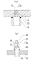
- Fig. 6
- greatly enlarged, an exemplary embodiment of the gas access to the gas supply pipes according to the invention including their connection to the relevant tube sheet,
- Fig. 7
- another exemplary embodiment of the gas access to the gas supply pipes,
- Fig. 8
- a third exemplary embodiment of the gas access to the gas supply pipes,
- Fig. 9
- yet another exemplary embodiment of the gas access to the gas supply pipes,
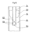
- Fig. 10
- a cut section of a reaction tube with the end of the gas supply tube in question and
- Fig. 11
- a diagram of a tube reactor according to the invention similar to that of FIG. 1, but with schematically specified means for a special type of temperature control along the contact tubes.
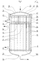
Der in Fig. 1 dargestellte Röhrenreaktor 2 besitzt in insoweit
üblicher Weise ein sich abgedichtet zwischen zwei Rohrböden 4
und 6 erstreckendes Reaktionsrohrbündel 8, das innerhalb eines
umgebenden Reaktormantels 10 von einem im Betrieb flussigen
Warmetrager, gewohnlich in Gestalt eines Salzbades, umspült
wird. In dem gezeigten Beispiel tritt Wärmeträger am gasaustrittsseitigen
Ende des Reaktormantels 10 durch einen Rohrstutzen
12 ein und am gaseintrittsseitigen Ende durch einen
Rohrstutzen 14 aus, jedoch könnten Ein- und Austritt des Warmeträgers
auch in bekannter Weise über Ringkanäle erfolgen,
ebenso wie der Warmeträger generell im Gleichstrom anstatt im
Gegenstrom in bezug auf das Reaktionsgasgemisch durch den Reaktormantel
10 hindurchtreten konnte. Sodann könnte das Reaktionsgasgemisch
auch von unten nach oben anstatt, wie gezeigt,
von oben nach unten durch die Reaktionsrohre 16 hindurchtreten.The
Den stirnseitigen Abschluß des Reaktors 2 bilden im wesentlichen
nach außen gewölbte Hauben 18 und 20 mit zentralen Gaseintritts-
und Gasaustrittsstutzen 22 bzw. 24. The front end of the
Wahrend jedoch bei herkömmlichen Röhrenreaktoren die gaseintrittsseitige
Haube selbst eine einzige mit den Reaktionsrohren
16 in Verbindung stehende Gaszuführungskammer bildet, um
den Reaktionsrohren fertig vorgemischtes Reaktionsgas zuzuführen,
ist bei dem Reaktor 2 gemäß Fig. 1 zwischen die gaseintrittsseitige
Haube, 18, und den gaseintrittsseitigen Rohrboden
4 zur Speisung der Reaktionsrohre 16 eine durch einen
seitlichen Rohrstutzen 26 hindurch speisbare erste Gaszufuhrungskammer
28 zwischengeschaltet, die von einer unter der
Haube 18 liegenden zweiten Gaszuführungskammer 30 durch einen
weiteren Rohrboden, 32, getrennt ist. In dem Rohrboden 32
sind, darin abgedichtet, nach unten hin bis in die Reaktionsrohre
16 hineinragende Gaszuführungsrohre 34 für die Einspeisung
eines zweiten gasförmigen Reaktanten verankert, der in
die zweite Gaszuführungskammer 30 durch den Gaseintrittsstutzen
22 hindurch eintritt. Der Rohrboden 32 ist abgedichtet
zwischen einem Flansch 36 der zylindrischen Seitenwand 38 und
einem entsprechenden Flansch 40 an der Haube 18 eingespannt.
Im Gegensatz zu den Rohrböden 4 und 6, die das Gewicht des
Rohrbündels 8 und zum Teil auch dasjenige des innerhalb des
Reaktormantels 10 befindlichen Wärmetragers zu tragen sowie
ggf. einer größeren Druckdifferenz zu widerstehen haben, kann
der Rohrboden 32 bei geringer Druckdifferenz zwischen dem ersten
und zweiten eingefuhrten Reaktanten verhaltnismäßig
leicht ausgeführt werden. Dies gilt umsomehr, wenn der Rohrboden
32, wie gezeigt, auf dem Rohrboden 4 mittels Tragstangen
42 abgestützt ist.However, in conventional tube reactors, the gas inlet side
Hood yourself with the
Innerhalb der Gaszuführungskammer 30 ist eine transversale
Gasverteilungsplatte 41 zu erkennen, die mit nach Strömungsverteilungsgesichtspunkten
variierenden Durchbrechungen prinzipiell
ähnlich gestaltet sein kann wie die in DE-C-2 201 528
(dort allerdings für den Warmeträger) angegebenen "Umlenkscheiben"
60 und 61.Inside the
Eine über Füße 44 mit einigem Abstand auf dem Rohrboden 4 aufliegende,
vorzugsweise aber dennoch gasdurchlassige Zentrierplatte
46 hält die unteren Enden der Gaszuführungsrohre 34 in
zentrierter Position in bezug auf die Reaktionsrohre 16. Bei
großer Gasdurchlässigkeit, wie sie bei einer solchen Platte
ohne weiteres zu verwirklichen ist, kann die Zentrierplatte 46
auch unmittelbar auf dem Rohrboden 4 aufliegen. Die Zentrierplatte
46 ist auf den Gaszuführungsrohren 34 verschiebbar.
Nach Entfernen der Haube 18 kann der Rohrboden 32 mitsamt den
Gaszuführungsrohren 34 und der Zentrierplatte 46 entnommen
werden, welche dabei auf Vorsprüngen an den unteren Enden der
Gaszuführungsrohre 34 zu liegen kommt, um so beim Wiederzusammenbau
die Einführung der Gaszuführungsrohre 34 in die zugehörigen
Reaktionsrohre 16 zu erleichtern.A resting on the
Soweit bei den nachfolgend beschriebenen weiteren Ausführungsbeispielen gleichartige Elemente auftreten, finden für diese die gleichen Bezugszeichen Verwendung wie bei dem Ausführungsbeispiel nach Fig. 1.So much for the further exemplary embodiments described below similar elements occur for them the same reference numerals use as in the embodiment according to Fig. 1.
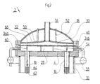
Gemäß Fig. 2 ist das Volumen der zweiten Gaszuführungskammer
30 von einem Einbau in Gestalt einer in die Haube 18 eingeschweißten
Platte 50 begrenzt, die sich an der Haube 18 über
Tragstangen 52 abstützt, ebenso wie der Rohrboden 32 sich an
dem Rohrboden 4 über Tragstangen 54 abstützt. Während die
Tragstangen 52 an die Haube 18 angeschweißt sind, ruhen die
Tragstangen 54 aus Demontierbarkeitsgründen auf dem Rohrboden
4 lose auf. 2 is the volume of the second
In diesem Fall erfolgt die Zuführung des zweiten Reaktanten zu
der zweiten Gaszuführungskammer 30 über ein massives, die Haube
18 durchsetzendes zentrales Rohr 56, das zugleich ebenfalls
der Abstützung der Platte 50 an der Haube 18 dienen kann. Wie
ersichtlich, ist die Platte 50 gewölbt, um auf diese Weise der
Kammer 30 eine nach außen zu abnehmende Höhe zu vermitteln,
welche der nach außen zu abnehmenden Menge des radial durch
die Kammer 30 hindurchtretenden zweiten Reaktanten entspricht,
um auf diese Weise der Kammer 30 ein kleinstmögliches Volumen
zu verleihen. Als weitere Variante gegenuber Fig. 1 erfolgt
die Zuführung des ersten Reaktanten zu der ersten Gaszuführungskammer
28 gemäß Fig. 2 aus einer Ringleitung 58 über eine
Mehrzahl radial einmündender Rohre 60. Dies erlaubt es, auch
die Gaszuführungskammer 28 niedrig und so ihr Volumen klein zu
halten, um auch die Zuführ des ersten Reaktanten - gewöhnlich
eines bereits für sich reaktionsfähigen Gemischs - rasch unterbinden
und überdies seine Verweildauer in dem Reaktor gering
halten zu können. Es hat sich nämlich gezeigt, daß die
Selbstzündwahrscheinlichkeit eines insofern kritischen Gasgemisches
mit der Dauer seines Bestehens zunimmt.In this case the second reactant is added
the second
In bezug auf die Gaszuführungsrohre 34 sind auf beiden Seiten
der Fig. 2 zwei Varianten gezeigt, die in Wirklichkeit alternativ
und nicht nebeneinander auftreten werden. Auf der linken
Seite ist ein Gaszuführungsrohr 34a in das betreffende Reaktionsrohr
14 hinein und bis unmittelbar vor eine darin befindliche
Katalysatorfüllung 62 reichend gezeigt, wahrend das Gaszuführungsrohr
34b auf der rechten Seite der Fig. 2 nur bis vor
das gaseintrittsseitige Ende des zugehörigen Reaktionsrohres
16 reicht. Statt frei vor der Katalysatorfüllung 62 könnte das
Gaszuführungsrohr 34a freilich auch innerhalb einer dieser
vorausgehenden Inertmaterialschicht enden. With respect to the
In beiden gezeigten Fällen ist am Ende des Gaszuführungsrohres
34 eine Mischdüse 64, hier in Gestalt eines Venturirohres, zu
erkennen, während sich am Eintrittsende des Gaszuführungsrohres
ein Drosselorgan 66 befindet, um den Gaszutritt zu wie
auch den Gasaustritt aus dem Gaszuführungsrohr 34 zu dosieren.
Diese Dosierung vermag erforderlichenfalls auch einem radialen
Druckabfall innerhalb der Gaszuführungskammer 30 Rechnung zu
tragen. Die Mischdüse 64 soll eine möglichst rasche und effektive
Beimischung des zweiten zu dem ersten Reaktanten bewirken.
Unter Umständen können an dem Gaszuführungsrohr (34) auch
mehrere solche Mischdüsen vorgesehen sein.In both cases shown is at the end of the gas supply pipe
34 a mixing
Es versteht sich, daß der betreffende Reaktor 2 in Wirklichkeit
weit mehr als die gezeigten zwei Reaktionsrohre 16 und
Gaszuführungsrohre 34 aufweisen wird und die Darstellung in
Fig. 2 (und weiteren) nur illustrativ zu verstehen ist.It is understood that the
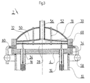
Die Ausführung gemäß Fig. 3 unterscheidet sich von derjenigen
nach Fig. 2 insoweit, als hier die Haube 18 mit der Gaszuführungskammer
28 eine Einheit bildet, indem der Rohrboden 32
ebenso wie die Platte 50 an die Haube 18, genauer gesagt einen
zylindrischen Flanschring 68 derselben, angeschweißt ist. In
diesem Fall ist an den Tragstangen 52 neben der Platte 50 auch
der Rohrboden 32 aufgehängt.3 differs from that
2 to the extent that here the
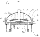
Nach Fig. 4 ist der Rohrboden 32 ebenso wie die Platte 50 konisch
bzw. gewölbt, um aus den vorausgehend genannten Gründen
neben der zweiten Gaszuführungskammer 30 auch der ersten Gaszuführungskammer
28 ein geringstmögliches Volumen und überdies
dem Rohrboden 32 größere Steifigkeit zu geben. Davon abgesehen
entspricht diese Ausführungsform weitgehend derjenigen aus
Fig. 3. 4, the
Nach Fig. 5 ist eine baulich separate zweite Gaszuführungskammer
30 innerhalb der ersten Gaszuführungskammer 28 angeordnet,
die in diesem Fall von einem an die Peripherie des Rohrbodens
4 anschließenden zylindrischen Flanschansatz 70 sowie der gaseintrittsseitigen
Haube 18 gebildet wird. Die Zuführung des
ersten Reaktanten zu der Gaszuführungskammer 28 erfolgt durch
einen außermittig in der Haube 18 angeordneten Rohrstutzen 72,
während die Zuführung des zweiten Reaktanten zu der Gaszuführungskammer
30 wiederum durch ein die Haube 18 durchsetzendes
zentrales Rohr 56 geschieht, das in diesem Fall jedoch zwecks
Demontierbarkeit der Kammer 30 geteilt ist.5 is a structurally separate second
Der Rohrboden 32 der Gaszuführungskammer 30 ist über Schraubbolzen
74 mit Abstand über dem Rohrboden 4 angebracht. Die
obere Begrenzung der Kammer 30 wird von einer flachen Schale
76 gebildet, die über hohle Schraubbolzen 78 mit dem Rohrboden
32 verschraubt ist. Fur den durch den Rohrstutzen 72 eintretenden
ersten Reaktanten ist die Kammer 30 umgehbar, und überdies
vermag er durch die hohlen Schraubbolzen 78 hindurchzutreten,
um so seinen Weg in die Reaktionsrohre 16 zu finden.The
In den Figuren 6 - 9 ist jeweils der Rohrboden 32 der zweiten
Gaszuführungskammer 30 mit einem darin ein- oder daran angeschweißten
Gaszuführungsrohr 34 sowie die betreffende Drosselstelle
66 zu erkennen. Gemäß Fig. 6 wird die Drosselstelle 66
von einer angefasten Bohrung 90 innerhalb einer Stirnwand 92
des Rohres 34, gemäß Fig. 7 von einem Bund 94 innerhalb einer
Durchbohrung 96 des Rohrbodens 32, gemäß Fig. 8 von einem hohlen,
entsprechend dimensionierten Schraubnippel 98 innerhalb
einer abgesetzten Durchbohrung 100 des Rohrbodens 32 und gemäß
Fig. 9 von einer durch eine Kreuzbohrung 102 seitlich zugängigen
axialen Bohrung 104 innerhalb eines massiven Endabschnitts
106 des betreffenden Rohres 34 in Verbindung mit einer axial
in bezug auf die Bohrung 104 verstellbaren Stiftschraube 108
gebildet, die in ihrer jeweiligen Stellung durch eine Kontermutter
110 fixierbar ist.In FIGS. 6-9, the
In Fig. 10 ist das stromabwärts gelegene Ende eines Gaszuführungsrohres
34 innerhalb des umgebenden Reaktionsrohres 16 zu
erkennen. Wie ersichtlich wird dieses Ende in bezug auf das
Rohr 16 durch Zentriermittel in Gestalt daran angebrachter
Flügel 120 zentriert, die zwecks Erleichterung der Einführung
in das Rohr 16 stirnseitig angefast sind. In bezug auf die in
Fig. 1 dargestellte Zentrierplatte 46 können die Flügel 120
zugleich die Vorsprünge bilden, auf denen die Zentrierplatte
bei Entfernung des Rohrbodens 32 mit den Gaszuführungsrohren
16 zur Auflage kommt.In Fig. 10 is the downstream end of a
Des weiteren zeigt die Figur eine Mischdüse 64 am Ende des
Gaszuführungsrohres 34, die mit einer Drosselstelle 122 ähnlich
dem vorausgehend beschriebenen Drosselorgan 66 am Anfang
des Gaszuführungsrohres 34 kombiniert ist, welche die gleiche
Funktion erfüllt. Im übrigen weist die hier gezeigte Mischdüse
64 neben einer stirnseitigen Gasaustrittsöffnung 124 mehrere
teils hintereinanderliegende, teils diametral einander gegenüberliegende
- oder auch kranzförmig verteilte - seitliche
Gasaustrittsöffnungen 126 auf. Bei am Anfang des Gaszuführungsrohres
angeordneter Drosselstelle, wie z.B. nach den Figuren
6 bis 9, könnten derartige seitliche Gasaustrittsstellen
sich auch weiter zum Rohranfang hin und selbst bis außerhalb
des jeweiligen Reaktionsrohres 16 fortsetzen, um so eine fortschreitende
und möglichst intensive Beimischung des zweiten
Reaktanten zu erreichen.Furthermore, the figure shows a mixing
Um das Mischungsverhältnis der Reaktanten in bezug auf die Gesamtheit
der Reaktionsrohre 16 noch weiter zu vergleichmäßigen,
als dies etwa vermittels der Drosselorgane an den Gaszuführungsrohren
möglich ist, kann dem ersten Reaktanten, z.B.
Ethylen, in herkömmlicher Weise bereits vor Eintritt in den
Reaktor 2 eine Teilmenge des zweiten Reaktanten, z.B. O2, bis
zu einer Größe zugemischt werden, welche für sich noch keine
riskante Mischung entstehen läßt. Damit nämlich läßt sich die
durch die Gaszuführungsrohre 34 im Reaktor 2 zugeführte Teilmenge
des zweiten Reaktanten entsprechend reduzieren.In order to further even out the mixing ratio of the reactants with respect to the entirety of the
Es sei angemerkt, daß in bezug auf das angegebene Beispiel O2
nicht notwendigerweise den durch die Gaszuführungsrohre zugegebenen
zweiten Reaktanten bilden muß. Vielmehr ist es auch
denkbar, O2 - oder ein unkritisches Ethylen-O2-Gemisch - als
ersten Reaktanten über die erste Gaszuführungskammer 28 und
Ethylen als zweiten Reaktanten über die zweite Gaszuführungskammer
hindurch zuzuführen.It should be noted that, with respect to the example given, O 2 need not necessarily form the second reactant added through the gas supply pipes. Rather, it is also conceivable to supply O 2 - or an uncritical ethylene-O 2 mixture - as the first reactants via the first
Fig. 11 zeigt, ebenso schematisch, einen im wesentlichen mit
demjenigen nach Fig. 1 übereinstimmenden Rohrenreaktor 2, der
allerdings innerhalb des Reaktormantels 10 durch eine transversale
Trennplatte 130 in zwei in bezug auf den Wärmeträgerkreislauf
unterschiedliche Bereiche, 132 und 134, unterteilt
ist. Derartige Maßnahmen sind, wie gesagt, der eingangs genannten
Veröffentlichung DE-C-2 201 528 (Fig. 5) zu entnehmen.Fig. 11 shows, also schematically, one with
1 corresponding
Links neben dem gezeigten Reaktor 2 ist diagrammäßig der Temperaturverlauf
innerhalb des Reaktors entlang den Reaktionsrohren
16 dargestellt.To the left of the
Während man mittels in dem Abschnitt 134 herbeigeführter Verdampfung
des Wärmeträgers die Temperatur auf konstantem Niveau
hält, läßt man in dem stromaufwärts gelegenen Abschnitt 132
die Temperatur des dort allein flüssigen Warmeträgers von dem
gaseintrittsseitigen Rohrboden 4 hinweg stetig ansteigen. Auf
diese Weise gelingt es, den Reaktor ohne Entzündungs- oder Explosionsgefahr
und selbst ohne Gefahr einer lokalen Überhitzung,
die an der nämlichen Stelle sogleich zu einer unerwünschten
Endreaktion führen könnte, unter noch größerer Beladung
des Reaktionsgasgemischs mit der kritischen Komponente,
wie zum Beispiel O2, zu fahren, als dies allein mit der verzögerten
Zufuhrung über die aus der sekundären Gaszuführungskammer
30 gespeisten Gaszuführungsrohre 34 möglich wäre.While the temperature is kept at a constant level by means of the evaporation of the heat carrier brought about in
Selbstverständlich lassen sich mit entsprechender Auslegung
des Wärmeträgerkreislaufs, ggf. in Verbindung mit mehreren
Trennplatten wie der in Fig. 11 gezeigten Trennplatte 130, gewunschtenfalls
auch noch kompliziertere Temperaturprofile entlang
den Reaktionsrohren 16 erreichen. Zumeist kann man annehmen,
daß die Reaktivität am Beginn der Reaktionsrohre infolge
des hohen O2-Anteils am höchsten ist, so daß es schon aus diesem
Grunde wünschenswert ist, dort eine vergleichsweise niedere
Temperatur zu haben, Im weiteren Verlauf der Reaktion nimmt
die Reaktivität ab, was durch Erhöhung der Wärmetragertemperatur
ausgeglichen werden kann. Ab einem bestimmten Umsetzungsgrad
hingegen erscheint eine weitere Temperaturerhöhung unangebracht.
In diesem Bereich also kann mit Verdampfung gearbeitet
werden.Of course, with an appropriate design of the heat transfer circuit, if necessary in conjunction with a plurality of partition plates such as
Der anfallende Dampf wird in einem Separator 136 von der flüssigen
Phase getrennt und einer anderweitigen Verwendung zugefuhrt,
während der flüssige Warmeträger in den Kreislauf zuruckgeführt
wird. Andererseits wird, bei 138, der als Dampf
abgeführte Warmeträger laufend ersetzt. Dazu stehen die Kreisläufe
der Reaktorabschnitte 132 und 134 bei 140 miteinander in
Verbindung. 142 ist ein Kühler und 144 eine Pumpe im Kreislauf
des Abschnitts 132. The steam produced is separated from the liquid in a
Sofern für beide Bereiche, 132 und 134, der gleiche Wärmeträger
Verwendung findet und umsomehr, wenn ohnehin, wie in Fig.
11 gezeigt, die Kreisläufe beider Abschnitte miteinander in
Verbindung stehen, braucht im übrigen die Trennplatte 130
nicht vollkommen dicht zu sein.Provided the same heat transfer medium for both areas, 132 and 134
Is used and even more so if in any case, as shown in Fig.
11, the circuits of both sections with each other in
The connection plate needs the
Unter Umständen kann das Reaktionsgas noch in der Gasauslaßkammer
146 unter der Haube 20 reaktionsfähig sein und so zu
einem Brand führen. In solchen Fällen empfiehlt es sich, das
Reaktionsgas noch vor Austritt aus den Reaktionsrohren 16 vermittels
des Wärmeträgers zu kuhlen und überdies, etwa durch
Einbauten, auch der Gasauslaßkammer 146 ein geringstmögliches
Volumen zu geben, um so die Verweilzeit des austretenden Reaktionsgases
darin zu verkürzen.Under certain circumstances, the reaction gas can still be in the
In bestimmten Fällen kann es auch noch wünschenswert sein, um so die Ausbeute pro Durchlauf noch weiter zu verbessern, bezuglich des hauptsächlichen Reaktionsgasstromes einen erfindungsgemäßen Röhrenreaktor mit einem oder mehreren gleich- oder auch andersartigen Reaktoren hintereinanderzuschalten.In certain cases it may also be desirable to so to improve the yield per run even further the main reaction gas stream according to the invention Tube reactor with one or more identical or to connect other types of reactors in series.
Claims (31)
- Tubular reactor (2) for carrying out exothermic gas phase reactions, comprising a reaction tube bundle (8) which extends in a sealed manner between two tube bottoms (4, 6), is flowed through by a reaction gas mixture, has a catalyst filling and within a surrounding reactor jacket (10) is passed around by a heat transfer medium, and comprising a hood (18, 20) which covers the respective tube bottom (4, 6) and is connected to a gas supply and gas discharge line, and comprising separate gas supply tubes (34) for a second reactant which project into the reaction tubes (16) on the gas inlet side and can be fed from a dedicated gas supply line, characterized in that within the gas-inlet-side hood (18) there is, besides a first gas supply chamber (28) that is connected to the interior of the reaction tubes (16), a second gas supply chamber (30) which can be fed separately with the second reactant, has a dedicated tube bottom (32) and is connected to the separate gas supply tubes (34), from which second gas supply chamber these separate gas supply tubes can be fed via in each case one dedicated flow control member (66; 122).
- Tubular reactor (2) according to Claim 1, characterized in that at least one of the two gas supply chambers (28, 30) has a significantly smaller volume than the available space under the gas-inlet-side hood (18) would allow.
- Tubular reactor (2) according to Claim 2, characterized in that the relevant gas supply chamber (28, 30) is made smaller than the available volume by means of at least one built-in component (50).
- Tubular reactor (2) according to Claim 3, characterized in that the built-in component consists of a plate (50) that is welded into the gas-inlet-side hood (18) in a transversely running manner.
- Tubular reactor (2) according to Claim 4, characterized in that the plate (50) is additionally supported in its middle region on the gas-inlet-side hood (18).
- Tubular reactor (2) according to Claim 5, characterized in that the support is formed at least partially by an appropriately sturdy central gas supply tube (56).
- Tubular reactor (2) according to any of Claims 4 to 6, characterized in that the plate (50), and possibly also the tube bottom (32) of the second gas supply chamber (30), is essentially curved or conical.
- Tubular reactor (2) according to any of the preceding claims, characterized in that the tube bottom (32) of the second gas supply chamber (30) is supported with respect to the gas-inlet-side tube bottom (4) of the reaction tube bundle (8) and/or with respect to the gas-inlet-side hood (18).
- Tubular reactor (2) according to any of the preceding claims, characterized in that the tube bottom (32) of the second gas supply chamber (30) is mounted between a flange (40) of the gas-inlet-side hood (18) and a flange (36) that is connected to the reactor jacket (10).
- Tubular reactor (2) according to any of Claims 1 to 8, characterized in that the tube bottom (32) of the second gas supply chamber (30), together with the latter, is releasably attached on the gas-inlet-side tube bottom (4) of the reaction tube bundle (8).
- Tubular reactor (2) according to any of Claims 1 to 8, characterized in that the entire second gas supply chamber (30) is integrated with the gas-inlet-side hood (18).
- Tubular reactor (2) according to any of the preceding claims, characterized in that the second gas supply chamber (30), together with the separate gas supply tubes (34) connected thereto and like the gas-inlet-side hood (18), can be removed.
- Tubular reactor (2) according to any of the preceding claims, characterized in that at least one of the two gas supply chambers (28, 30) has a gas distribution plate (41) with openings of varying cross section.
- Tubular reactor (2) according to any of the preceding claims, characterized in that at least one of the gas supply chambers (28, 30) has a height that increases and decreases, with regard to the flow distribution, in the direction away from the longitudinal centre axis of the reactor.
- Tubular reactor (2) according to any of the preceding claims, characterized in that the separate gas supply tubes (34) are guided through a - preferably gas-permeable - centring plate (46) before entering the reaction tubes (16).
- Tubular reactor (2) according to Claim 15, characterized in that the centring plate (46) can be displaced on the separate gas supply tubes (34) in principle up to the free ends thereof.
- Tubular reactor (2) according to any of the preceding claims, characterized in that the separate gas supply tubes (34) have, at their free ends, centring means (120) for centring them with respect to the associated reaction tubes (16).
- Tubular reactor (2) according to any of the preceding claims, characterized in that the separate gas supply tubes (34) have, at least at their free ends, mixing nozzles (64) for swirling the second reactant, fed by said separate gas supply tubes, with the first reactant.
- Tubular reactor (2) according to any of the preceding claims, characterized in that the flow control members (66) of the separate gas supply tubes (34) can be adjusted individually.
- Tubular reactor (2) according to Claim 18 or 19, characterized in that the flow control members (122) in each case form a unit with the mixing nozzles (64).
- Tubular reactor (2) according to any of the preceding claims, characterized in that the separate gas supply tubes (34) in each case have a number of gas outlet points distributed over their length.
- Tubular reactor (2) according to Claim 21, characterized in that some of the relevant gas outlet points still lie outside the reaction tubes (16).
- Tubular reactor (2) according to any of the preceding claims, characterized in that the separate gas supply tubes (34) still end before the catalyst filling (62) contained in the respective reaction tube (16).
- Tubular reactor (2) according to Claim 23, characterized in that the separate gas supply tubes (34) end in an inert material layer placed in front of the catalyst filling (62).
- Tubular reactor (2) according to any of the preceding claims, characterized in that the heat transfer medium cycle has a device which raises the operating temperature along the reaction tubes from a relatively low value at the gas inlet end of the reaction tubes (16).
- Tubular reactor (2) according to Claim 25, characterized in that the heat transfer medium cycle furthermore has a device which keeps the operating temperature constant in another section of the reaction tubes (16) that is located downstream.
- Tubular reactor (2) according to Claim 26, characterized in that in the region of the relevant tube section there is a device for evaporating the heat transfer medium.
- Tubular reactor (2) according to any of the preceding claims, characterized in that the heat transfer medium cycle has a device which lowers the operating temperature towards the gas outlet end of the reaction tubes (16).
- Tubular reactor (2) according to any of the preceding claims, characterized in that a gas outlet chamber (146) within the gas-outlet-side hood (20) has a volume that is as low as possible, by virtue of built-in components or the like.
- Tubular reactor (2) according to any of the preceding claims, characterized in that there is a device which mixes part of the second reactant, fed into the reaction tubes by the separate gas supply tubes (34), with the first reactant prior to entry into the reactor.
- Tubular reactor (2) according to any of the preceding claims, characterized in that, with respect to the main flow of reaction gas, it is connected in series with one or more identical or different reactors.
Applications Claiming Priority (3)
| Application Number | Priority Date | Filing Date | Title |
|---|---|---|---|
| DE10021986 | 2000-05-05 | ||
| DE10021986A DE10021986A1 (en) | 2000-05-05 | 2000-05-05 | Tubular reactor for safe exothermic gas reaction, e.g. catalytic oxidation of hydrocarbons, includes separate chambers for reagent gases and concentric mixing tube system |
| PCT/EP2001/005030 WO2001085332A1 (en) | 2000-05-05 | 2001-05-04 | Tubular reactor for carrying out exothermic gas phase reactions |
Publications (2)
| Publication Number | Publication Date |
|---|---|
| EP1292383A2 EP1292383A2 (en) | 2003-03-19 |
| EP1292383B1 true EP1292383B1 (en) | 2004-08-04 |
Family
ID=7640934
Family Applications (1)
| Application Number | Title | Priority Date | Filing Date |
|---|---|---|---|
| EP01933928A Expired - Lifetime EP1292383B1 (en) | 2000-05-05 | 2001-05-04 | Tubular reactor for carrying out exothermic gas phase reactions |
Country Status (8)
| Country | Link |
|---|---|
| US (1) | US20030175183A1 (en) |
| EP (1) | EP1292383B1 (en) |
| JP (1) | JP4147519B2 (en) |
| KR (1) | KR20030022114A (en) |
| AT (1) | ATE272441T1 (en) |
| DE (2) | DE10021986A1 (en) |
| ES (1) | ES2225543T3 (en) |
| WO (1) | WO2001085332A1 (en) |
Cited By (1)
| Publication number | Priority date | Publication date | Assignee | Title |
|---|---|---|---|---|
| CN101462033B (en) * | 2007-12-20 | 2012-09-26 | 曼德韦有限公司 | Tube bundle reactor |
Families Citing this family (19)
| Publication number | Priority date | Publication date | Assignee | Title |
|---|---|---|---|---|
| KR100450234B1 (en) * | 2002-07-10 | 2004-09-24 | 주식회사 엘지화학 | Catalytic oxidation reactor with enhanced heat exchanging system |
| US20040129676A1 (en) * | 2003-01-07 | 2004-07-08 | Tan Roy H. | Apparatus for transfer of an array of liquids and methods for manufacturing same |
| WO2004067164A1 (en) * | 2003-01-31 | 2004-08-12 | Man Dwe Gmbh | Tubular reactor for carrying out catalytic gas-phase reactions and method for operating said reactor |
| WO2004067165A1 (en) * | 2003-01-31 | 2004-08-12 | Man Dwe Gmbh | Multi-zone tubular reactor for carrying out exothermic gas-phase reactions |
| DE102004040472A1 (en) | 2004-08-20 | 2006-03-02 | Man Dwe Gmbh | Method and tube bundle reactor for carrying out endothermic or exothermic gas phase reactions |
| CN1803271B (en) * | 2005-12-14 | 2010-09-01 | 微宏科技(湖州)有限公司 | Diverter and high flux parallel catalytic reaction device |
| US8334395B2 (en) * | 2007-12-14 | 2012-12-18 | Dow Technology Investments Llc | Hydrocarbon/oxygen industrial gas mixer with coarse water droplet environment to reduce ignition potential |
| WO2009078899A1 (en) * | 2007-12-14 | 2009-06-25 | Dow Technology Investments Llc | Oxygen/hydrocarbon rapid (high shear) gas mixer, particularly for the production of ethylene oxide |
| CA2701306C (en) * | 2007-12-14 | 2015-10-20 | Dow Technology Investments Llc | Low shear gas mixer |
| WO2009078897A1 (en) * | 2007-12-14 | 2009-06-25 | Dow Technology Investments Llc | Hydrocarbon/oxygen industrial gas mixer with water mist |
| WO2009078900A1 (en) * | 2007-12-14 | 2009-06-25 | Dow Technology Investments Llc | Wet scrubbing for removing particulate solids from oxygen supply line |
| CN102361687B (en) * | 2009-01-21 | 2015-05-13 | 巴斯夫欧洲公司 | Tube bundle reactor for non-catalyzed or homogenously catalyzed reactions |
| CN102600787A (en) * | 2012-03-30 | 2012-07-25 | 凯莱英医药集团(天津)股份有限公司 | Continuous ozonization reaction device and working method thereof |
| EP3271062B1 (en) * | 2015-03-20 | 2019-02-27 | Haldor Topsøe A/S | Boiling water reactor |
| DE102015114885A1 (en) | 2015-09-04 | 2017-03-09 | Thyssenkrupp Ag | Catalytic reactor |
| CN105396515B (en) * | 2015-10-23 | 2018-05-04 | 湖南安淳高新技术有限公司 | Radially air cooling reactor |
| US10159953B2 (en) * | 2015-11-12 | 2018-12-25 | Uop Llc | Reactor for use with an ionic liquid catalyst |
| CN109956449B (en) * | 2017-12-14 | 2022-07-26 | 中国科学院大连化学物理研究所 | Parallel flow type methanol-water reforming hydrogen production reactor |
| US11559799B2 (en) * | 2020-12-22 | 2023-01-24 | Scientific Design Company, Inc. | Removable impingement basket for ethylene oxide (EO) reactors |
Family Cites Families (12)
| Publication number | Priority date | Publication date | Assignee | Title |
|---|---|---|---|---|
| US3268299A (en) * | 1961-12-27 | 1966-08-23 | Crawford & Russell Inc | Apparatus for effecting chemical reactions |
| US3518284A (en) * | 1967-02-20 | 1970-06-30 | Shell Oil Co | Partial oxidation of organic compounds |
| DE1667247A1 (en) * | 1967-12-27 | 1971-09-16 | Texaco Ag | Device for evenly distributing liquid to a plurality of reaction tubes in a reactor for performing chemical reactions |
| US3931273A (en) * | 1970-02-23 | 1976-01-06 | Costruzioni Meccaniche G. Mazzoni S.P.A. | Method for sulphonatizing and sulphatizing organic compounds with sulphur trioxide and apparatus therefor |
| US4173615A (en) * | 1974-07-08 | 1979-11-06 | Mitsui Toatsu Chemicals, Incorporated | Chemical apparatus for corrosive materials |
| US4221763A (en) * | 1978-08-29 | 1980-09-09 | Cities Service Company | Multi tube high pressure, high temperature reactor |
| JPH0673625B2 (en) * | 1986-11-12 | 1994-09-21 | 三菱重工業株式会社 | Reactor |
| JPH01261201A (en) * | 1988-04-12 | 1989-10-18 | Mitsubishi Gas Chem Co Inc | Hydrocarbon reforming reactor |
| IT1255737B (en) * | 1992-05-19 | 1995-11-15 | MULTITUBULAR FALLING FILM REACTOR | |
| GB9516125D0 (en) * | 1995-08-07 | 1995-10-04 | Ici Plc | Heat exchange apparatus and process |
| US5723094A (en) * | 1996-10-29 | 1998-03-03 | Arco Chemical Technology, L.P. | Reactor for chemical reactions |
| DE19723322A1 (en) * | 1997-06-04 | 1998-12-10 | Bayer Ag | Reactor for carrying out rapid, strongly exothermic reactions and their use |
-
2000
- 2000-05-05 DE DE10021986A patent/DE10021986A1/en not_active Withdrawn
-
2001
- 2001-05-04 JP JP2001581982A patent/JP4147519B2/en not_active Expired - Fee Related
- 2001-05-04 KR KR1020027014826A patent/KR20030022114A/en active IP Right Grant
- 2001-05-04 WO PCT/EP2001/005030 patent/WO2001085332A1/en active IP Right Grant
- 2001-05-04 EP EP01933928A patent/EP1292383B1/en not_active Expired - Lifetime
- 2001-05-04 AT AT01933928T patent/ATE272441T1/en not_active IP Right Cessation
- 2001-05-04 US US10/275,204 patent/US20030175183A1/en not_active Abandoned
- 2001-05-04 ES ES01933928T patent/ES2225543T3/en not_active Expired - Lifetime
- 2001-05-04 DE DE50103136T patent/DE50103136D1/en not_active Expired - Lifetime
Cited By (1)
| Publication number | Priority date | Publication date | Assignee | Title |
|---|---|---|---|---|
| CN101462033B (en) * | 2007-12-20 | 2012-09-26 | 曼德韦有限公司 | Tube bundle reactor |
Also Published As
| Publication number | Publication date |
|---|---|
| JP4147519B2 (en) | 2008-09-10 |
| WO2001085332A1 (en) | 2001-11-15 |
| ATE272441T1 (en) | 2004-08-15 |
| JP2004515332A (en) | 2004-05-27 |
| KR20030022114A (en) | 2003-03-15 |
| EP1292383A2 (en) | 2003-03-19 |
| DE10021986A1 (en) | 2001-11-15 |
| WO2001085332B1 (en) | 2002-02-21 |
| DE50103136D1 (en) | 2004-09-09 |
| ES2225543T3 (en) | 2005-03-16 |
| US20030175183A1 (en) | 2003-09-18 |
Similar Documents
| Publication | Publication Date | Title |
|---|---|---|
| EP1292383B1 (en) | Tubular reactor for carrying out exothermic gas phase reactions | |
| DE60109326T2 (en) | CATALYTIC REACTOR WITH HEAT EXCHANGER FOR ENDOTHERMIC AND EXOTHERMIC CHEMICAL REACTIONS | |
| EP1587612B1 (en) | Tubular reactor for carrying out catalytic gas-phase reactions and method for operating said reactor | |
| EP0819101B1 (en) | Plant and process for oxidizing an aqueous medium | |
| EP2389241B1 (en) | Tube bundle reactor and process for non-catalyzed or homogenously catalyzed reactions | |
| DE69822766T2 (en) | Method and device for improving the purity of a product using a simulated moving bed | |
| EP1586370B1 (en) | Reactor arrangement for carrying out catalytic gas reactions | |
| WO1990006807A1 (en) | Tube reactor | |
| DE102015122129A1 (en) | Reactor for carrying out exo- or endothermic reactions | |
| EP1569744A1 (en) | Jacketed tube reactor comprising a bypass line for the heat transfer medium | |
| DE1300880B (en) | Method and device for the continuous thickening of sugar syrup | |
| DE69725096T2 (en) | Pressure equalization and flushing device in one container | |
| EP1681094A2 (en) | Reactor with two or more separate reaction chambers | |
| EP3338883B1 (en) | Apparatus and process for transferring gas into a plurality of process fluids | |
| DE3037817A1 (en) | GAS MIXING DEVICE | |
| DE19723322A1 (en) | Reactor for carrying out rapid, strongly exothermic reactions and their use | |
| DE60317545T2 (en) | METHOD FOR IMPLEMENTING HARD EXOTHEROUS OXIDATION REACTIONS UNDER PSEUDO-ISOTHERMAL CONDITIONS | |
| EP0150835B1 (en) | Process for the oxidation of liquid organic substances | |
| DE4037284A1 (en) | Tubular reactor for continuous fluidic chemical reaction under pressure - comprises pulsators acting on opposite ends of tube to increase efficiency of ammonolysis, oxy- and cyanoethylation and saponification | |
| EP1016439B1 (en) | Device for carrying out distillations and heterogeneous catalytic reactions | |
| EP0792672B1 (en) | Process and apparatus for the continuous extraction of polymer granules | |
| EP0210680B1 (en) | Tube reactor | |
| DE2312572C2 (en) | Catalytic reactor | |
| DE19852894A1 (en) | Phthalic anhydride generated by the controlled partial oxidation of o-xylene or naphthalene in high-yield catalytic reactor with reduced by-products | |
| DE1620947C3 (en) | Process and device for the polymerization of ethylene at high pressures and temperatures in the presence of catalysts which form free radicals |
Legal Events
| Date | Code | Title | Description |
|---|---|---|---|
| PUAI | Public reference made under article 153(3) epc to a published international application that has entered the european phase |
Free format text: ORIGINAL CODE: 0009012 |
|
| 17P | Request for examination filed |
Effective date: 20021009 |
|
| AK | Designated contracting states |
Kind code of ref document: A2 Designated state(s): AT BE CH CY DE DK ES FI FR GB GR IE IT LI LU MC NL PT SE TR |
|
| 17Q | First examination report despatched |
Effective date: 20030731 |
|
| GRAP | Despatch of communication of intention to grant a patent |
Free format text: ORIGINAL CODE: EPIDOSNIGR1 |
|
| RAP1 | Party data changed (applicant data changed or rights of an application transferred) |
Owner name: MAN DWE GMBH |
|
| GRAS | Grant fee paid |
Free format text: ORIGINAL CODE: EPIDOSNIGR3 |
|
| GRAA | (expected) grant |
Free format text: ORIGINAL CODE: 0009210 |
|
| AK | Designated contracting states |
Kind code of ref document: B1 Designated state(s): AT BE CH CY DE DK ES FI FR GB GR IE IT LI LU MC NL PT SE TR |
|
| PG25 | Lapsed in a contracting state [announced via postgrant information from national office to epo] |
Ref country code: IE Free format text: LAPSE BECAUSE OF FAILURE TO SUBMIT A TRANSLATION OF THE DESCRIPTION OR TO PAY THE FEE WITHIN THE PRESCRIBED TIME-LIMIT Effective date: 20040804 Ref country code: FI Free format text: LAPSE BECAUSE OF FAILURE TO SUBMIT A TRANSLATION OF THE DESCRIPTION OR TO PAY THE FEE WITHIN THE PRESCRIBED TIME-LIMIT Effective date: 20040804 Ref country code: TR Free format text: LAPSE BECAUSE OF FAILURE TO SUBMIT A TRANSLATION OF THE DESCRIPTION OR TO PAY THE FEE WITHIN THE PRESCRIBED TIME-LIMIT Effective date: 20040804 |
|
| REG | Reference to a national code |
Ref country code: GB Ref legal event code: FG4D Free format text: NOT ENGLISH |
|
| REG | Reference to a national code |
Ref country code: CH Ref legal event code: EP |
|
| REG | Reference to a national code |
Ref country code: IE Ref legal event code: FG4D Free format text: GERMAN |
|
| REF | Corresponds to: |
Ref document number: 50103136 Country of ref document: DE Date of ref document: 20040909 Kind code of ref document: P |
|
| PG25 | Lapsed in a contracting state [announced via postgrant information from national office to epo] |
Ref country code: GR Free format text: LAPSE BECAUSE OF FAILURE TO SUBMIT A TRANSLATION OF THE DESCRIPTION OR TO PAY THE FEE WITHIN THE PRESCRIBED TIME-LIMIT Effective date: 20041104 Ref country code: SE Free format text: LAPSE BECAUSE OF FAILURE TO SUBMIT A TRANSLATION OF THE DESCRIPTION OR TO PAY THE FEE WITHIN THE PRESCRIBED TIME-LIMIT Effective date: 20041104 Ref country code: DK Free format text: LAPSE BECAUSE OF FAILURE TO SUBMIT A TRANSLATION OF THE DESCRIPTION OR TO PAY THE FEE WITHIN THE PRESCRIBED TIME-LIMIT Effective date: 20041104 |
|
| GBT | Gb: translation of ep patent filed (gb section 77(6)(a)/1977) |
Effective date: 20041020 |
|
| ET | Fr: translation filed | ||
| REG | Reference to a national code |
Ref country code: ES Ref legal event code: FG2A Ref document number: 2225543 Country of ref document: ES Kind code of ref document: T3 |
|
| REG | Reference to a national code |
Ref country code: IE Ref legal event code: FD4D |
|
| PG25 | Lapsed in a contracting state [announced via postgrant information from national office to epo] |
Ref country code: LU Free format text: LAPSE BECAUSE OF NON-PAYMENT OF DUE FEES Effective date: 20050504 Ref country code: AT Free format text: LAPSE BECAUSE OF NON-PAYMENT OF DUE FEES Effective date: 20050504 Ref country code: CY Free format text: LAPSE BECAUSE OF FAILURE TO SUBMIT A TRANSLATION OF THE DESCRIPTION OR TO PAY THE FEE WITHIN THE PRESCRIBED TIME-LIMIT Effective date: 20050504 |
|
| PG25 | Lapsed in a contracting state [announced via postgrant information from national office to epo] |
Ref country code: MC Free format text: LAPSE BECAUSE OF NON-PAYMENT OF DUE FEES Effective date: 20050531 Ref country code: CH Free format text: LAPSE BECAUSE OF NON-PAYMENT OF DUE FEES Effective date: 20050531 Ref country code: LI Free format text: LAPSE BECAUSE OF NON-PAYMENT OF DUE FEES Effective date: 20050531 |
|
| PLBE | No opposition filed within time limit |
Free format text: ORIGINAL CODE: 0009261 |
|
| STAA | Information on the status of an ep patent application or granted ep patent |
Free format text: STATUS: NO OPPOSITION FILED WITHIN TIME LIMIT |
|
| 26N | No opposition filed |
Effective date: 20050506 |
|
| REG | Reference to a national code |
Ref country code: CH Ref legal event code: PL |
|
| PG25 | Lapsed in a contracting state [announced via postgrant information from national office to epo] |
Ref country code: PT Free format text: LAPSE BECAUSE OF NON-PAYMENT OF DUE FEES Effective date: 20050104 |
|
| PGFP | Annual fee paid to national office [announced via postgrant information from national office to epo] |
Ref country code: ES Payment date: 20110525 Year of fee payment: 11 Ref country code: FR Payment date: 20110607 Year of fee payment: 11 |
|
| PGFP | Annual fee paid to national office [announced via postgrant information from national office to epo] |
Ref country code: GB Payment date: 20110520 Year of fee payment: 11 Ref country code: BE Payment date: 20110511 Year of fee payment: 11 Ref country code: NL Payment date: 20110520 Year of fee payment: 11 |
|
| PGFP | Annual fee paid to national office [announced via postgrant information from national office to epo] |
Ref country code: IT Payment date: 20110524 Year of fee payment: 11 Ref country code: DE Payment date: 20110520 Year of fee payment: 11 |
|
| BERE | Be: lapsed |
Owner name: *MAN DWE G.M.B.H. Effective date: 20120531 |
|
| REG | Reference to a national code |
Ref country code: NL Ref legal event code: V1 Effective date: 20121201 |
|
| GBPC | Gb: european patent ceased through non-payment of renewal fee |
Effective date: 20120504 |
|
| PG25 | Lapsed in a contracting state [announced via postgrant information from national office to epo] |
Ref country code: BE Free format text: LAPSE BECAUSE OF NON-PAYMENT OF DUE FEES Effective date: 20120531 Ref country code: IT Free format text: LAPSE BECAUSE OF NON-PAYMENT OF DUE FEES Effective date: 20120504 |
|
| REG | Reference to a national code |
Ref country code: FR Ref legal event code: ST Effective date: 20130131 |
|
| REG | Reference to a national code |
Ref country code: DE Ref legal event code: R119 Ref document number: 50103136 Country of ref document: DE Effective date: 20121201 |
|
| PG25 | Lapsed in a contracting state [announced via postgrant information from national office to epo] |
Ref country code: NL Free format text: LAPSE BECAUSE OF NON-PAYMENT OF DUE FEES Effective date: 20121201 |
|
| PG25 | Lapsed in a contracting state [announced via postgrant information from national office to epo] |
Ref country code: FR Free format text: LAPSE BECAUSE OF NON-PAYMENT OF DUE FEES Effective date: 20120531 Ref country code: GB Free format text: LAPSE BECAUSE OF NON-PAYMENT OF DUE FEES Effective date: 20120504 |
|
| PG25 | Lapsed in a contracting state [announced via postgrant information from national office to epo] |
Ref country code: DE Free format text: LAPSE BECAUSE OF NON-PAYMENT OF DUE FEES Effective date: 20121201 |
|
| REG | Reference to a national code |
Ref country code: ES Ref legal event code: FD2A Effective date: 20130823 |
|
| PG25 | Lapsed in a contracting state [announced via postgrant information from national office to epo] |
Ref country code: ES Free format text: LAPSE BECAUSE OF NON-PAYMENT OF DUE FEES Effective date: 20120505 |