EP1292177A1 - Method for preparing substrate for flexible print wiring board and substrate for flexible print wiring board - Google Patents
Method for preparing substrate for flexible print wiring board and substrate for flexible print wiring board Download PDFInfo
- Publication number
- EP1292177A1 EP1292177A1 EP01936955A EP01936955A EP1292177A1 EP 1292177 A1 EP1292177 A1 EP 1292177A1 EP 01936955 A EP01936955 A EP 01936955A EP 01936955 A EP01936955 A EP 01936955A EP 1292177 A1 EP1292177 A1 EP 1292177A1
- Authority
- EP
- European Patent Office
- Prior art keywords
- polyimide
- based resin
- resin precursor
- substrate
- precursor
- Prior art date
- Legal status (The legal status is an assumption and is not a legal conclusion. Google has not performed a legal analysis and makes no representation as to the accuracy of the status listed.)
- Withdrawn
Links
Classifications
-
- H—ELECTRICITY
- H05—ELECTRIC TECHNIQUES NOT OTHERWISE PROVIDED FOR
- H05K—PRINTED CIRCUITS; CASINGS OR CONSTRUCTIONAL DETAILS OF ELECTRIC APPARATUS; MANUFACTURE OF ASSEMBLAGES OF ELECTRICAL COMPONENTS
- H05K1/00—Printed circuits
- H05K1/02—Details
-
- H—ELECTRICITY
- H05—ELECTRIC TECHNIQUES NOT OTHERWISE PROVIDED FOR
- H05K—PRINTED CIRCUITS; CASINGS OR CONSTRUCTIONAL DETAILS OF ELECTRIC APPARATUS; MANUFACTURE OF ASSEMBLAGES OF ELECTRICAL COMPONENTS
- H05K1/00—Printed circuits
- H05K1/02—Details
- H05K1/03—Use of materials for the substrate
- H05K1/0313—Organic insulating material
- H05K1/032—Organic insulating material consisting of one material
- H05K1/0346—Organic insulating material consisting of one material containing N
-
- C—CHEMISTRY; METALLURGY
- C08—ORGANIC MACROMOLECULAR COMPOUNDS; THEIR PREPARATION OR CHEMICAL WORKING-UP; COMPOSITIONS BASED THEREON
- C08G—MACROMOLECULAR COMPOUNDS OBTAINED OTHERWISE THAN BY REACTIONS ONLY INVOLVING UNSATURATED CARBON-TO-CARBON BONDS
- C08G73/00—Macromolecular compounds obtained by reactions forming a linkage containing nitrogen with or without oxygen or carbon in the main chain of the macromolecule, not provided for in groups C08G12/00 - C08G71/00
- C08G73/06—Polycondensates having nitrogen-containing heterocyclic rings in the main chain of the macromolecule
- C08G73/10—Polyimides; Polyester-imides; Polyamide-imides; Polyamide acids or similar polyimide precursors
- C08G73/1003—Preparatory processes
- C08G73/1007—Preparatory processes from tetracarboxylic acids or derivatives and diamines
-
- C—CHEMISTRY; METALLURGY
- C08—ORGANIC MACROMOLECULAR COMPOUNDS; THEIR PREPARATION OR CHEMICAL WORKING-UP; COMPOSITIONS BASED THEREON
- C08L—COMPOSITIONS OF MACROMOLECULAR COMPOUNDS
- C08L79/00—Compositions of macromolecular compounds obtained by reactions forming in the main chain of the macromolecule a linkage containing nitrogen with or without oxygen or carbon only, not provided for in groups C08L61/00 - C08L77/00
- C08L79/04—Polycondensates having nitrogen-containing heterocyclic rings in the main chain; Polyhydrazides; Polyamide acids or similar polyimide precursors
- C08L79/08—Polyimides; Polyester-imides; Polyamide-imides; Polyamide acids or similar polyimide precursors
-
- H—ELECTRICITY
- H05—ELECTRIC TECHNIQUES NOT OTHERWISE PROVIDED FOR
- H05K—PRINTED CIRCUITS; CASINGS OR CONSTRUCTIONAL DETAILS OF ELECTRIC APPARATUS; MANUFACTURE OF ASSEMBLAGES OF ELECTRICAL COMPONENTS
- H05K1/00—Printed circuits
- H05K1/02—Details
- H05K1/03—Use of materials for the substrate
- H05K1/0313—Organic insulating material
- H05K1/0353—Organic insulating material consisting of two or more materials, e.g. two or more polymers, polymer + filler, + reinforcement
- H05K1/036—Multilayers with layers of different types
-
- Y—GENERAL TAGGING OF NEW TECHNOLOGICAL DEVELOPMENTS; GENERAL TAGGING OF CROSS-SECTIONAL TECHNOLOGIES SPANNING OVER SEVERAL SECTIONS OF THE IPC; TECHNICAL SUBJECTS COVERED BY FORMER USPC CROSS-REFERENCE ART COLLECTIONS [XRACs] AND DIGESTS
- Y10—TECHNICAL SUBJECTS COVERED BY FORMER USPC
- Y10T—TECHNICAL SUBJECTS COVERED BY FORMER US CLASSIFICATION
- Y10T428/00—Stock material or miscellaneous articles
- Y10T428/31504—Composite [nonstructural laminate]
- Y10T428/31551—Of polyamidoester [polyurethane, polyisocyanate, polycarbamate, etc.]
-
- Y—GENERAL TAGGING OF NEW TECHNOLOGICAL DEVELOPMENTS; GENERAL TAGGING OF CROSS-SECTIONAL TECHNOLOGIES SPANNING OVER SEVERAL SECTIONS OF THE IPC; TECHNICAL SUBJECTS COVERED BY FORMER USPC CROSS-REFERENCE ART COLLECTIONS [XRACs] AND DIGESTS
- Y10—TECHNICAL SUBJECTS COVERED BY FORMER USPC
- Y10T—TECHNICAL SUBJECTS COVERED BY FORMER US CLASSIFICATION
- Y10T428/00—Stock material or miscellaneous articles
- Y10T428/31504—Composite [nonstructural laminate]
- Y10T428/31551—Of polyamidoester [polyurethane, polyisocyanate, polycarbamate, etc.]
- Y10T428/31605—Next to free metal
Definitions
- the present invention relates to a method for preparing a substrate for a flexible print wiring board, and to a substrate for a flexible print wiring board. More specifically, the invention relates to a method for preparing a substrate for a flexible print wiring board, and to a substrate for a flexible print wiring board, the substrate being free from a curl, a twist and a warp after formation of circuitry thereon and excellent in heat resistance, dimensional stability, adhesion and electrical properties.
- substrates for flexible print wiring boards are produced by combining an electrically conducting material with an insulator such as a polyimide film or a polyester film with the intervention of an adhesive such as of an epoxy resin or an acrylic resin.
- an adhesive such as of an epoxy resin or an acrylic resin.
- a substrate for a substrate for a flexible print wiring board produced by such a method is inferior in heat resistance and flame resistance because of the intervention of an adhesive layer.
- the substrate suffers from a greater dimensional variation when the electrically conducting material is etched or when the substrate is subjected to a certain heat treatment, thereby causing trouble in subsequent steps.
- Japanese Unexamined Patent Publication No. 60-157286 (1985) proposes a method for producing a substrate for a flexible print wiring board, wherein a solution of a polyimide precursor having a specific structure is applied directly on an electrically conducting material and then cured.
- the electrically conducting material is partly etched away for formation of circuitry on the substrate for a flexible print wiring board produced by this method, the substrate is significantly curled with its conductor-etched surface facing inward.
- the inventors of the present invention have found that the intended substrate for a flexible print wiring board can be obtained by employing two specific polyimide resin precursors for formation of a polyimide resin layer, and achieved the present invention.
- a production method for a substrate for a flexible print wiring board comprises: applying a polyimide-based resin precursor solution directly on an electrically conducting material for formation of a polyimide-based resin precursor layer; and thermalcuring.
- the polyimide-based resin precursor layer for production of a flexible print wiring substrate having a polyimide-based resin layer; wherein a solution of one polyimide-based resin precursor (B) out of two types of polyimide-based resin precursors is applied directly on the electrically conducting material; wherein a solution of the other polyimide-based resin precursor (A) is applied on a layer of the polyimide-based resin precursor (B), the polyimide-based resin precursor (A) being capable of relieving a residual strain occurring in a polyimide-based resin resulting from thermalcuring of the polyimide-based resin precursor (B).
- a flexible print wring board substrate according to the present invention is produced by the aforesaid production method.
- the residual strain occurring in the polyimide-based resin layer due to shrinkage of the layer during the thermalcuring is relieved, whereby a curl, a twist and a warp of the substrate can be suppressed.
- a production method as set forth in claim 1 of the present invention comprises: applying a polyimide-based resin precursor solution directly on an electrically conducting material for formation of a polyimide-based resin precursor layer; and thermalcuring the polyimide-based resin precursor layer for production of a flexible print wiring substrate having a polyimide-based resin layer; wherein a solution of one polyimide-based resin precursor (B) out of two types of polyimide-based resin precursors is applied directly on the electrically conducting material; wherein a solution of the other polyimide-based resin precursor (A) is applied on a layer of the polyimide-based resin precursor (B), the polyimide-based resin precursor (A) being capable of relieving a residual strain occurring in a polyimide-based resin resulting from thermalcuring of the polyimide-based resin precursor (B).
- a polyimide-based resin precursor having a higher thermalcuring rate than the polyimide-based resin precursor (B) is employed as the polyimide-based resin precursor (A).
- a polyimide-based resin precursor having a thermalcuring rate index higher than that of the polyimide-based resin precursor (B) by not smaller than 10% is employed as the polyimide-based resin precursor (A).
- a polyimide-based resin precursor having a thermalcuring rate index higher than that of the polyimide-based resin precursor (B) by not smaller than. 30% is employed as the polyimide-based resin precursory (A).
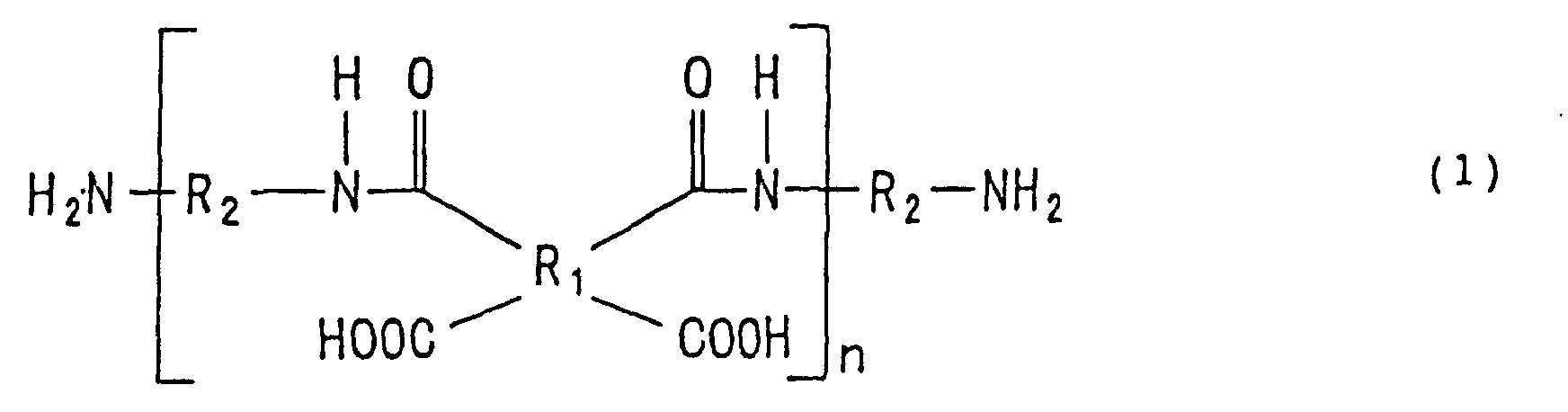
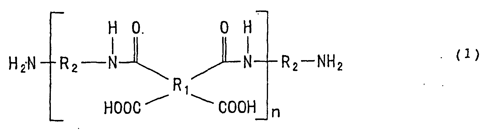
- the polyimide-based resin precursor (B) comprises a polyamic acid, or a salt or a mixture of a diamine represented by the following structural formula (1) and a tetracarboxylic acid derivative represented by the following structural formula (2), and the polyimide-based resin precursor (A) comprises a polyamic.
- the content of the tetracarboxylic acid derivative in the polyimide-based resin precursor (A) is greater than the content of the tetracarboxylic acid derivative in the polyimide-based resin precursor (B), wherein R 1 is a tetravalent aromatic residue, R 2 is a divalent aromatic residue, and n is a real number not smaller than one which represents an average number, wherein R 3 is a tetravalent aromatic residue, and R 4 is a hydrogen atom or an alkyl group.
- the polyimide-based resin precursor (B) comprises a polyamic acid, a trialkylamine derivative of the polyamic acid, or a mixture of the polyamic acid and the trialkylamine derivative
- the polyimide-based resin precursor (A) comprises a polyamic acid, a trialkylamine derivative of the polyamic acid, or a mixture of the polyamic acid and the trialkylamine derivative and has a greater trialkylamine content than the polyimide-based resin precursor (B).
- a production method as set forth in claim 7 of the invention comprises: applying a polyimide-based resin precursor solution directly on an electrically conducting material to form a polyimide-based resin precursor layer; and thermalcuring the polyimide-based resin precursor layer for production of a flexible print wiring substrate having a polyimide-based resin layer; wherein a solution of a polyimide-based resin precursor (B) comprising a polyamic acid, or a salt or a mixture of a diamine represented by the following structural formula (1) and pyromellitic acid or biphenyl-3,4,3',4'-tetracarboxylic acid is applied directly on the electrically conducting material; wherein a solution of a polyimide-based resin precursor (A) comprising a polyamic acid, or a salt or a mixture of a diamine represented by the following structural formula (1) and pyromellitic acid or biphenyl-3,4,3',4'- tetracarboxylic acid and containing pyromellitic acid or
- a production method as set forth in claim 8 of the invention comprises: applying a polyimide-based resin precursor solution directly on an electrically conducting material to form a polyimide-based resin precursor layer; and thermalcuring the polyimide-based resin precursor layer for production of a flexible print wiring substrate having a polyimide-based resin layer; wherein a solution of a polyimide-based resin precursor (B) comprising a polyamic acid, a triethylamine derivative of the polyamic acid or a mixture of the polyamic acid and the triethylamine derivative is applied directly on the electrically conducting material; wherein a solution of a polyimide-based resin precursor (A) comprising a polyamic acid, a triethylamine derivative of the polyamic acid or a mixture of the polyamic acid and the triethylamine derivative and containing triethylamine in a greater amount than the polyimide-based resin precursor (B) is applied on a layer of the polyimide-based resin precursor (B).
- a substrate for a flexible print wiring board as set forth in claim 9 of the invention is produced by a production method as recited in any of claims 1 to 6.
- a substrate for a flexible print wiring board as set forth in claim 10 of the invention is produced by a production method as recited in claim 7 or 8.
- the polyimide-based resin precursor (A), the polyimide-based resin precursor (B), the solution of the polyimide-based resin precursor (A) and the solution of the polyimide-based resin precursor (B) are referred to simply as "precursor (A)", “precursor (B)", “solution (A)” and “solution (B)”, respectively.
- the polyimide-based resins are intended to include heat resistant resins such as polyimides, polyamide-imides, polybenzimidazoles and polyimide esters.
- the polyimide-based resins preferably each comprise a polyimide resin as a main component thereof. Therefore, the polyimide-based resin precursors are imidized into the polyimide-based resins.
- a polyimide-based resin precursor having a higher thermalcuring rate than the precursor (B) is preferably employed as the precursor (A).
- the thermalcuring rate of the polyimide-based resin precursor is determined, for examples in the following manner.
- a varnish of the polyimide-based resin precursor is applied on a 3-mm thick glass plate, and heat-treated at 350 ° C for two hours. Then, the resulting coated film is peeled off at a room temperature, and sufficiently pulverized in an agate mortar. The resulting powder is homogeneously mixed with fine KBr powder in the mortar, and the resulting mixture is pressed into a KBr disk by means of a press machine. After the KBr disk is dried in a desiccator for not shorter than 12 hours, an infrared spectrum is obtained with the use of the KBr disk by means of a Fourier transformation infrared spectrophotometer System-2000 (with a TGS detector for 64-time integration) available from the Perkin-Elmer Corporation.
- a Fourier transformation infrared spectrophotometer System-2000 with a TGS detector for 64-time integration
- an infrared spectrum is obtained in substantially the same manner as described above, except that the heat treatment is performed at a temperature of 160 ° C for 10 minutes.
- thermalcuring rate index c is calculated from (a/b) ⁇ 100(%).
- the thermalcuring rate index c indicates the imide ring opening ratio of the polyimide-based resin precursor. The higher the value of the thermalcuring rate index, the higher the thermalcuring rate of the polyimide-based resin precursor.
- a polyimide-based resin precursor having a thermalcuring rate index higher than that of the precursor (B) by not smaller than 10% is preferably employed as the precursor (A).
- a polyimide-based resin precursor having a thermalcuring rate index higher than that of the precursor (B) by not smaller than 30% is more preferably employed as the precursor (A).
- polyimide-based resin precursors are as follows.
- a polyimide-based resin precursor comprising a polyamic acid, a trialkylamine derivative of the polyamic acid or a mixture of the polyamic acid and the trialkylamine derivative is employed as the precursor (B).
- a polyimide-based resin precursor comprising a polyamic acid, a trialkylamine derivative of the polyamic acid or a mixture of the polyamic acid and the trialkylamine derivative and having a greater trialkylamine content than the precursor (B) is employed as the precursor (A).
- the precursor (B) may contain no trialkylamine.
- Alkyl groups in the trialkylamine derivative of the polyamic acid preferably each have a carbon number of 1 to 10.
- the alkyl groups in the trialkylamine derivative may be linear, branched or cyclic.
- the three alkyl groups may be the same or different.
- trialkylamine derivative of the polyamic acid examples include a trimethylamine derivative, a triethylamine derivative, a triisopropylamine derivative, a tri(n-propyl)amine derivative, a triisobutylamine derivative, a tri(n-butyl)amine derivative, a tri(t-butyl)amine derivative, a cyclohexyldimethylamine derivative and a butyldimethylamine derivative of the polyamic acid, but not limited thereto.
- the trialkylamine preferably has a boiling point of not higher than 200 ° C so as to evaporate together with a solvent at imidization.
- polyimide-based resin precursors are as follows.
- a polyimide-based resin precursor comprising a polyamic acid, or a salt or a mixture of a diamine represented by the aforesaid structural formula (1) and a tetracarboxylic acid derivative represented by the aforesaid structural formula (2) is employed as the precursor (B).
- a polyimide-based resin precursor comprising a polyamic acid, or a salt or a mixture of a diamine represented by the aforesaid structural formula (1) and a tetracarboxylic acid derivative represented by the aforesaid structural formula (2) and containing the tetracarboxylic acid derivative in a greater amount than the precursor (B) is employed as the precursor (A).
- the precursor (B) may contain no tetracarboxylic acid derivative.
- metal foils made from metals such as copper, aluminum, iron, silver, palladium, nickel, chromium, molybdenum, tungsten, and alloys of any of these metals.
- metal foils a copper foil is most preferable.
- the electrically conducting material may be subjected to a chemical or mechanical surface treatment for improvement of the adhesion thereof to the polyimide-based resin.
- chemical surface treatment include plating treatments such as plating with nickel and plating with a copper-zinc alloy, and treatments with an aluminum alcoholate, an aluminum chelate and a silane coupling agent.
- a silane coupling agent having an amino group is preferably employed as the silane coupling agent.
- An exemplary mechanical surface treatment is sandblasting.
- the polyimide-based resin precursors are applied as solutions thereof on the electrically conducting material.
- exemplary solvents to be employed for dissolving the polyimide-based resin precursors include non-protonic polar solvents, ether compounds and water-soluble alcohol compounds.
- non-protonic polar solvents examples include N-methyl-2-pyrrolidone, N,N-dimethylformamide, N,N-dimethylacetamide, dimethyl sulfoxide and hexamethylphosphoramide.
- ether compounds examples include 2-methoxyethanol, 2-ethoxyethanol, 2-(methoxymethoxy)ethoxyethanol, 2-isopropoxyethanol, 2-butoxyethanol, tetrahydrofurfuryl alcohol, diethylene glycol, diethylene glycol monomethyl ether, diethylene glycol monoethyl ether, diethylene glycol monobutyl ether, triethylene glycol, triethylene glycol monoethyl ether, tetraethylene glycol, 1-methoxy-2-propanol, 1-ethoxy-2-propanol, dipropylene glycol, dipropylene glycol monomethyl ether, dipropylene glycol monoethyl ether, tripropylene glycol monomethyl ether, polyethylene glycol, polypropylene glycol, tetrahydrofuran, dioxane, 1,2-dimethoxyethane, diethylene glycol dimethyl ether, and diethylene glycol diethyl ether.
- water-soluble alcohol compounds examples include methanol, ethanol, 1-propanol, 2-propanol, tert-butyl alcohol, ethylene glycol, 1,2-propandiol, 1,3-propandiol, 1,3-butandiol, 1,4-butandiol, 2,3-butandiol, 1,5-pentandiol, 2-buten-1,4-diol, 2-methyl-2,4-pentandiol, 1,2,6-hexantriol, and diacetone alcohol.
- solvents may be used as a mixture of two or more of them.
- N,N-dimethylacetamide or N-methyl-2-pyrrolidone alone. It is also preferred to use a combination of N,N-dimethylacetamide and N-methyl-2-pyrrolidone, a combination of N-methyl-2-pyrrolidone and methanol, or a combination of N-methyl-2-pyrrolidone and 2-methoxyethanol as a solvent mixture.
- the solution of the polyamic acid is prepared by allowing an aromatic tetracarboxylic dianhydride represented by the following structural formula (3) and an aromatic diamine represented by the following structural formula (4) to react with each other in any of the aforesaid solvents, e.g., in a non-protonic polar solvent.
- R 1 is a tetravalent aromatic residue
- R 2 is a divalent aromatic residue.
- the proportion of the tetracarboxylic dianhydride is preferably 1.03 to 0.97 mol, more preferably 1.01 to 0.99 mol, based on 1 mol of the diamine.
- a reaction temperature is preferably -30 to 60 ° C, more preferably -20 to 40 °C.
- the mixing order of the monomers and the solvent is not particularly limited, but the monomers and the solvent may be mixed in any order.
- the solution of the polyamic acid is obtained by dissolving or dispersing the respective monomers in different solvents, mixing the resulting solutions or dispersions together, and allowing the monomers to react with each other with stirring at a predetermined temperature for a predetermined period.
- the trialkylamine derivative of the polyamic acid is obtained, for example, by adding 0.2 to 1.0 mol, preferably 0.3 to 0.8 mol, of the trialkylamine based on 1 mol of carboxyl groups of the polyamic acid to the solution of the polyamic acid in the non-protonic polar solvent obtained in the aforesaid manner, and allowing the trialkylamine and the polyamic acid to react with each other at 10 to 90° C, preferably at 20 to 80°C.
- the trialkylamine derivative of the polyamic acid can be obtained by addition of the trialkylamine during the preparation of the polyamic acid.
- the solution (A) and the solution (B) are different in the content of the trialkylamine derivative.
- the precursor (A) is preferably present in a greater proportion than the precursor (B) by not smaller than 1 % by mass, more preferably not smaller than 2 % by mass, based on the total weight of the precursors (A) and (B).
- the solution of the polyimide-based resin precursor comprising the salt of the diamine represented by the structural formula (1) and the tetracarboxylic acid derivative represented by the structural formula (2) is prepared by adding the tetracarboxylic acid derivative represented by the structural formula (2) to the solution of the diamine represented by the structural formula (1).
- the aromatic tetracarboxylic dianhydride represented by the structural formula (3) and the aromatic diamine represented by the structural formula (4) are allowed to react with each other in the non-protonic polar solvent to prepare the solution of the diamine represented by the structural formula (1).
- the proportion of the tetracarboxylic dianhydride is preferably 0.50 to 0.95 mol, more preferably 0.60 to 0.90 mol, based on 1 mol of the diamine.
- a reaction temperature is preferably -30 to 60 ° C, more preferably -20 to 40 ° C.
- the aromatic tetracarboxylic acid derivative represented by the structural formula (2) is added to the solution of the diamine represented by the structural formula (1), whereby the solution of the polyimide resin precursor comprising the salt of the diamine and the aromatic tetracarboxylic acid derivative is prepared.
- the aromatic tetracarboxylic acid derivative represented by the structural formula (2) is preferably added in a proportion of 0.97/2 to 1.03/2 mol, more preferably 0.99/2 to 1.01/2 mol, based on one equivalent of amino groups in the diamine represented by the structural formula (1).
- a diamine When the solution of the diamine represented by the structural formula (1) is prepared, a diamine may be used alone or two types of diamines may be used as a mixture.
- the mixing order of the monomers of the aforesaid aromatic tetracarboxylic dianhydride and the aforesaid aromatic diamine and the solvent is not particularly limited, but the monomers and the solvent may be mixed in any order.
- the solution of the diamine represented by the structural formula (1) is prepared by dissolving or dispersing the respective monomers in different solvents, mixing the resulting solutions or dispersions together, and allowing the monomers to react with each other with stirring at a predetermined temperature for a predetermined period.
- the tetracarboxylic acid derivative represented by the structural formula (2) may be added in a solid or solution form to the aforesaid diamine solution with stirring.
- the tetracarboxylic acid derivatives may be used either alone or as a mixture of two of them.
- Two or more types of the polyimide resin precursor solutions may be used as a mixture.
- aromatic tetracarboxylic acid derivative represented by the structural formula (2) include:
- aromatic tetracarboxylic dianhydride represented by the structural formula (3) examples include dianhydrides of the aforesaid aromatic tetracarboxylic acids. These aromatic tetracarboxylic dianhydrides may be used as a mixture of two or more of them.
- aromatic diamine represented by the structural formula (4) examples include:
- the solution (A) and the solution (B) are different in the content of the aromatic tetracarboxylic acid derivative.
- the precursor (A) is preferably present in a greater proportion than the precursor (B) by not smaller than 1 % by mass, more preferably not smaller than 2 % by mass, based on the total weight of the precursors (A) and (B).
- a derivative of an amine, a diamine, a dicarboxylic acid, a tricarboxylic acid and a tetracarboxylic acid having unsaturated bonds may additionally be employed for forming a crosslinked structure during the thermalcuring when the polyimide resin precursor solution is prepared.
- unsaturated compounds are maleic acid, nadic acid, tetrahydrophthalic acid and ethynylaniline.
- a polyimide resin, a polyamide-imide resin or other heat-resistant resin soluble in the aforesaid solvent may be mixed with the solutions.
- a silane coupling agent and any of various surface-active agents may be added in a very small amount to the solutions for improvement of adhesion (adhesiveness) and film properties.
- the solution (A) and the solution (B) prepared according to each of the aforesaid embodiments are applied on the electrically conducting material, and dried for formation of precursor layers, which are then thermally cured to be imidized.
- the polyimide resin layer is formed which includes a coated film (A) resulting from the imidization of the precursor (A) contained in the solution (A) and a coated film (B) resulting from the imidization of the precursor (B) contained in the solution (B).
- the solution (B) is applied directly on the electrically conducting material, and the solution (A) is applied on a layer of the solution (B).
- the solution (B) is applied on a roughened surface of the electrically conducting material having a predetermined thickness so as to allow the coated film (B) to have a predetermined thickness after the thermalcuring.
- the applied solution (B) is preferably dried at a temperature of not higher than 200° C, more preferably not higher than 150°C for formation of a precursor coated film as an inner layer.
- the solution (A) is applied on the precursor coated film so as to allow the coated film (A) to have a predetermined thickness after the thermalcuring.
- the applied solution (A) is preferably dried at a temperature of not higher than 200 ° C, more preferably not higher than 150 ° C for formation of a precursor coated film as an outer layer.
- the substrate for a flexible print wiring board which includes the coated film (A) and the coated film (B) formed as the insulative polyimide-based resin layer on the electrically conducting material.
- the application of the solution (A) and the solution (B) may be carried out a plurality of times, and then the resulting coated films may be thermally cured. Further, two or more polyimide-based resin layers each including the coated film (B) and the coated film (A) may be formed.
- polyimide resin precursors have been explained as the polyimide-based resin precursors
- the substrate for a flexible print wiring board can be produced in the same manner by employing other polyimide-based resin precursors.
- a layer of another polyimide-based resin or any other heat-resistant resin may additionally be formed between the electrically conducting material and the polyimide-based resin layer for improvement of the adhesion (adhesiveness) or coating properties.
- the thickness (t1) of the coated film (A) and the thickness (t2) of the coated film (B) after the thermalcuring may be the same, but the thickness ratio (t2/t1) is preferably 0.01 to 100, more preferably 0.1 to 10, further more preferably 0.3 to 3.
- the thickness (t1+t2) of the entire polyimide-based resin layer is typically 5 to 100 ⁇ m, preferably 10 to 50 ⁇ m.
- the polyimide-based resin layer preferably has an average linear expansion coefficient of 10 to 40 ppm.
- the chemical structures of the polyimide-based resins of the two coated films or the linear expansion coefficients of the two polyimide-based resins of the coated films which depend on the chemical structures may be the same or different.
- the linear expansion coefficient of the coated film (B) in contact with the electrically conducting material may be higher or lower than the linear expansion coefficient of the coated film (A).
- a polyimide-based resin precursor which allows resolving a residual strain generated in the polyimide-based resin layer formed by the thermalcuring of the precursor (B), is employed as the precursor (A).
- a residual strain of the polyimide-based resin formed by the thermalcuring of the precursor (B), which is generated between the precursor (B) and the electrically conducting material is counterbalanced with that of the polyimide-based resin formed by the thermalcuring of the precursor (A), which is generated between the precursor (A) and the precursor (B).
- the residual strain generated in the polyimide-based resin between the electrically conducting material and the polyimide-based resin layer is resoled, so that a curl, a twist and a warp can be suppressed.
- the substrate is improved in dimensional stability and electrical properties such as an insulation breakdown voltage, and excellent in heat resistance, adhesion, flexural resistance and chemical resistance.
- the optimum thicknesses of the layers of the precursors (A) and (B) formed on the electrically conducting material are determined by a simple trial-and-error method, though the optimum thicknesses depend on the basic chemical structures of the polyimide-based resin precursors. Where the curl of the substrate is not sufficiently suppressed after the etching of the substrate, for example, the thicknesses of the precursor layers to be stacked are simply increased or reduced for adjustment.
- a die coater for the application of the polyimide-based resin precursors on the electrically conducting material, a die coater, a multi-layer die coater, a gravure coater, a comma coater, a reverse roll coater, a doctor blade coater or the like can be employed as an industrial coating machine.
- a thermalcuring of the applied precursors a copper foil on which the precursors are applied is wound up into a roll and then heated in an inert gas atmosphere in an oven, or a heating zone is provided in a production line.
- the polyimide-based resin layer is formed from the specific polyimide-based resin precursors as described above, so that the curl, the twist and the warp are suppressed after formation of circuitry.
- the substrate for a flexible print wiring board is excellent in heat resistance, dimensional stability at high temperatures, adhesion and electrical properties.
- the substrate for a flexible print wiring board Since the curl, twist and warp of the substrate for a flexible print wiring board are suppressed according the present invention, electronic components can be mounted at a higher integration density on the substrate for a flexible print wiring board without any trouble. Further, the substrate for a flexible print wiring board is excellent in heat resistance, dimensional stability at high temperatures, adhesion and electrical properties.
- Reference Examples 1 to 10 show preparation of polyimide resin precursor solutions. Compounds.employed in Reference Examples 1 to 10 are abbreviated as follows.
- the precursor solutions (a) to (c) prepared in Reference Examples 1 to 3 contained no tetracarboxylic acid derivative, and the reaction components contained no trialkylamine. Therefore, the trialkylamine content was 0 % by mass.
- a homogeneous polyimide resin precursor solution containing a salt of a diamine and a tetracarboxylic acid was prepared.
- This solution was defined as a precursor solution (g).
- the content of a tetracarboxylic acid derivative in the precursor solution was 11.8 % by mass.
- a polyimide resin precursor solution was prepared in substantially the same manner as in Reference Example 7, except that 220.67 g (0.75 mol) of BPDA, 82.56 g (0.25 mol) of BPA-A, 992 g of DMAc and 425 g of NMP were employed. This solution was defined as a precursor solution (h).. The content of a tetracarboxylic acid derivative in the precursor solution was 19.4 % by mass.
- a polyamide resin precursor solution was prepared in substantially the same manner as in Reference Example 7, except that BPA-E was employed instead of BPA-A.
- This solution was defined as a precursor solution (i).
- the content of a dimethyl tetracarboxylate in the precursor solution was 0.8 % by mass.
- the precursor solution (a) and the precursor solution (h) were blended in amounts such as to contain equivalent amounts of the polyimide resin precursors. Thus, a homogeneous polyimide resin precursor solution was prepared. This solution was defined as a precursor solution (j). The content of a tetracarboxylic acid derivative in the precursor solution was 9.7 % by mass.
- thermalcuring rate indices of the polyimide resin precursors contained in the precursor solutions (a) to (j) prepared in Reference Examples 1 to 10 were determined. In Table 1, the results are shown together with the content of the tetracarboxylic acid derivative or the trialkylamine.
- a 35- ⁇ m thick copper foil produced by electrolysis was fixed in a metal frame.
- the precursor solution (a) was applied on the copper foil by means of a bar coater to such a thickness that the resulting coated film (B) had a thickness of 5 ⁇ m after thermalcuring. Then, the applied solution was dried at 130 ° C for ten minutes for formation of an inner layer. Subsequently, the precursor solution (g) was applied on the inner layer in a room temperature atmosphere (25°C) by means of a bar coater to such a thickness that the resulting coated film (A) had a thickness of 20 ⁇ m after thermalcuring. Then, the applied solution was dried at 100 ° C for five minutes for formation of an outer layer.
- the inner and outer layers were subjected to a heat treatment by increasing the temperature from 100 ° C to 360 ° C in two hours and then keeping the temperature at 360 ° C for two hours, whereby the precursor in the inner layer and the precursor in the outer layer were thermally cured to be imidized.
- a substrate for a flexible print wiring board (copper tensile board) was produced, which had a polyimide resin layer including the coated film (B) and the coated film (A) formed on the coated film (B).
- a substrate for a flexible print wiring board was produced in the same manner as in Example 1, except that the precursor solution (h) was employed instead of the precursor solution (g) and the coated film (B) and the coated film (A) respectively had thicknesses of 17 ⁇ m and 8 ⁇ m.
- Adhesion between the copper foil and the resin layer of the substrate for a flexible print wiring board was measured by means of TENSILONTESTER (a versatile precision material tester MODEL-2020 available from Intesco).
- the substrates were each cut into a 10-mm wide strip, which was fixed to an aluminum plate with its resin layer in contact with the aluminum plate by a two-sided adhesive tape having an adhesive applied on opposite sides thereof.
- the copper foil was peeled apart from the resin layer in a 180-degree direction at 50 mm/minute for determination of the adhesion.
- the result is excellent with an adhesion of 1.6 kg/cm.
- the substrate for a flexible print wiring board was immersed in an aqueous solution of ferric chloride, so that the copper foil was entirely etched away from the substrate by the ferric chloride aqueous solution.
- the linear expansion coefficient and second-order transition temperature Tg of the resin layer obtained after the etching were determined by means of a thermo-mechanical analyzer (TMA: TMA2940 available from TA Instruments). As a result, the linear expansion coefficient was 23 ppm, and the second-order transition temperature Tg was 345° C. It was found that the resin layer was excellent in dimensional stability and heat resistance.
- a substrate for a flexible print wiring board was produced in substantially the same manner as in Example 1, except that the precursor solution (i) was employed instead of the precursor solution (g) and the coated film (B) and the coated film (A) respectively had thicknesses of 14 ⁇ m and 11 ⁇ m.
- a substrate for a flexible print wiring board was produced in substantially the same manner as in Example 1, except that the precursor solution (j) was employed instead of the precursor solution (g) and the coated film (B) and the coated film (A) respectively had thicknesses of 4 ⁇ m and 21 ⁇ m.
- a substrate for a flexible print wiring board was produced in substantially the same manner as in Example 1, except that the precursor solution (j) and the precursor solution (h) were employed instead of the precursor solution (a) and the precursor solution (g), respectively, and the coated film (B) and the coated film (A) respectively had thicknesses of 12 ⁇ m and 9 ⁇ m.
- a substrate for a flexible print wiring board was produced in substantially the same manner as in Example 1, except that the precursor solution (b) and the precursor solution (d) were employed instead of the precursor solution (a) and the precursor solution (g), respectively, and the coated film (B) and the coated film (A) respectively had thicknesses of 14 ⁇ m and 11 ⁇ m.
- a substrate for a flexible print wiring board was produced in substantially the same manner as in Example 1, except that the precursor solution (c) and the precursor solution (e) were employed instead of the precursor solution (a)andtheprecursorsolution(g), respectively, and the coated film (B) and the coated film (A) respectively had thicknesses of 14 ⁇ m and 11 ⁇ m.
- a substrate for a flexible print wiring board was produced in substantially the same manner as in Example 5, except that the coated film (A) had a thickness of 15 ⁇ m.
- a substrate for a flexible print wiring board was produced in substantially the same manner as in Example 1, except that the precursor solution (e) was employed instead of the precursor solution (g) and the coated film (B) and the coated film (A) respectively had thicknesses of 11 ⁇ m and 14 ⁇ m.
- a substrate for a flexible print wiring board was produced in substantially the same manner as in Example 1, except that the precursor solution (c) and the precursor solution (f) were employed instead of the precursor solution (a) and the precursor solution (g), respectively, and the coated film (B) and the coated film (A), respectively had thicknesses of 5 ⁇ m and 20 ⁇ m.
- a substrate for a flexible print wiring board was produced in substantially the same manner as in Example 1, except that the precursor solution (a) was employed instead of the precursor solution (g), and the coated film (B) and the coated film (A) respectively had thicknesses of 10 ⁇ m and 15 ⁇ m.
- a substrate for a flexible print wiring board was produced in substantially the same manner as in Example 1, except that the precursor solution (g) and the precursor solution (a) were employed instead of the precursor solution (a) and the precursorsolution (g), respectively, and the coated film (B) and the coated film (A) respectively had thicknesses of 10 ⁇ m and 15 ⁇ m.
- a substrate for a flexible print wiring board was produced in substantially the same manner as in Example 1, except that the precursor solution (h) and the precursor solution (a) were employed instead of the precursor solution (a) and the precursor solution (g), respectively, and the coated film (B) and the coated film (A) respectively had thicknesses of 10 ⁇ m and 15 ⁇ m.
- a substrate for a flexible print wiring board was produced in substantially the same manner as in Example 1, except that the precursor solution (j) and the precursor solution (a) were employed instead of the precursor solution (a) and the precursor solution (g), respectively, and the coated film (B) and the coated film (A) respectively had thicknesses of 10 ⁇ m and 15 ⁇ m.
- a substrate for a flexible print wiring board was produced in substantially the same manner as in Example 1, except that the precursor solution (e) and the precursor solution (a) were employed instead of the precursor solution (a) and the precursor solution (g), respectively, and the coated film (B) and the coated film (A) respectively had thicknesses of 10 ⁇ m and 15 ⁇ m.
- a substrate for a flexible print wiring board was produced in substantially the same manner as in Example 1, except that the precursor solution (c) was employed instead of the precursor solution (g) and the coated film (B) and the coated film (A) respectively had thicknesses of 14 ⁇ m and 11 ⁇ m.
- test strips having a length of 10 cm and a width of 10 cm were dried at 100 ° C for 10 minutes, and the curvature radii of the resulting curls of the test strips were measured.
- a symbol ⁇ indicates that the curvature radius of the curl was smaller than 20 mm
- a symbol ⁇ indicates that the curvature radius was smaller than 50 mm and not smaller than 20 mm
- a symbol ⁇ indicates that the curvature radius was smaller than 90 mm and not smaller than 50 mm
- a symbol o ⁇ indicates that the curvature radius was not smaller than 90 mm.
- Example Curl resistant properties Pre-etching Post-etching 1 ⁇ o ⁇ 2 ⁇ o ⁇ 3 ⁇ o ⁇ 4 ⁇ o ⁇ 5 ⁇ o ⁇ 6 ⁇ ⁇ 7 ⁇ ⁇ 8 ⁇ o ⁇ 9 ⁇ ⁇ 10 ⁇ ⁇ Comparative Example Curl resistant properties Pre-etching Post-etching 1 ⁇ ⁇ 2 ⁇ ⁇ 3 ⁇ ⁇ 4 ⁇ ⁇ 5 ⁇ ⁇ 6 ⁇ ⁇ Comparative Example Curl resistant properties Pre-etching Post-etching 1 ⁇ ⁇ 2 ⁇ ⁇ 3 ⁇ ⁇ 4 ⁇ ⁇ 5 ⁇ ⁇ 6 ⁇ ⁇
- the substrate for a flexible print wiring boards of Examples 1 to 10 each having an outer layer formed of a precursor having a higher thermalcuring rate index than that of an inner layer are less liable to be curled with excellent curl resistant properties. Therefore, electronic components can be mounted at a higher integration density on the substrate for a flexible print wiring boards.
- the substrate for a flexible print wiring board of Comparative Example 1 having an inner layer and an outer layer formed of precursors having the same thermalcuring rate indices, and the substrate for a flexible print wiring boards of Comparative Examples 2 to 6 each having an inner layer formed of a precursor having a higher thermalcuring rate index than that of an outer layer are more liable to be curled with poor curl resistant properties.
- the substrate for a flexible print wiring board produced in accordance with the inventive production method is excellent in heat resistance, dimensional stability, and adhesion between the copper foil and the resin layer.
Landscapes
- Chemical & Material Sciences (AREA)
- Health & Medical Sciences (AREA)
- Chemical Kinetics & Catalysis (AREA)
- Medicinal Chemistry (AREA)
- Polymers & Plastics (AREA)
- Organic Chemistry (AREA)
- Engineering & Computer Science (AREA)
- Microelectronics & Electronic Packaging (AREA)
- Macromolecular Compounds Obtained By Forming Nitrogen-Containing Linkages In General (AREA)
- Laminated Bodies (AREA)
Abstract
Description



- BPDA:
- biphenyl-3,3',4,4'-tetracarboxylic dianhydride
- BPA-A:
- biphenyl-3,3',4,4'-tetracarboxylic acid
- BPA-E:
- dimethyl biphenyl-3,3',4,4'-tetracarboxylate
- PMDA:
- pyromellitic dianhydride
- ODA:
- 4,4'-oxydianiline
- PDA:
- p-phenylenediamine
- DMAc:
- N,N-dimethylacetamide
- NMP:
- N-methyl-2-pyrrolidone
| Reference Example | Precursor solution | Content of tetracarboxylic acid derivative (% by mass) | Content of Trialkylamine (% by mass) | Thermalcuring rate index (%) |
| 1 | (a) | 0 | 0 | 16 |
| 2 | (b) | 0 | 0 | 19 |
| 3 | (c) | 0 | 0 | 13 |
| 4 | (d) | 0 | 2.1 | 27 |
| 5 | (e) | 0 | 5.1 | 34 |
| 6 | (f) | 0 | 5.9 | 28 |
| 7 | (g) | 11.8 | - | 67 |
| 8 | (h) | 19.4 | - | 80 |
| 9 | (i) | 20.8 | - | 82 |
| 10 | (j) | 9.7 | - | 55 |
| Example | ||||
| Precursor solution | Thickness of Coated film (µm) | |||
| Inner layer | Outer layer | B | A | |
| 1 | a | g | 5 | 20 |
| 2 | a | h | 17 | 8 |
| 3 | a | i | 14 | 11 |
| 4 | a | j | 4 | 21 |
| 5 | j | h | 12 | 9 |
| 6 | b | d | 14 | 11 |
| 7 | c | e | 14 | 11 |
| 8 | j | h | 12 | 15 |
| 9 | a | e | 11 | 14 |
| 10 | c | f | 5 | 20 |
| Comparative Example | ||||
| Precursor solution | Thickness of coated film (µm) | |||
| Inner layer | Outer layer | B | A | |
| 1 | a | a | 10 | 15 |
| 2 | g | a | 10 | 15 |
| 3 | h | a | 10 | 15 |
| 4 | j | a | 10 | 15 |
| 5 | e | a | 10 | 15 |
| 6 | a | c | 14 | 11 |
| Example | Curl resistant properties | |
| Pre-etching | Post-etching | |
| 1 | ○ | o ○ |
| 2 | ○ | o ○ |
| 3 | ○ | o ○ |
| 4 | ○ | o ○ |
| 5 | ○ | o ○ |
| 6 | ○ | ○ |
| 7 | ○ | ○ |
| 8 | ○ | o ○ |
| 9 | ○ | ○ |
| 10 | ○ | ○ |
| Comparative Example | Curl resistant properties | |
| Pre-etching | Post-etching | |
| 1 | ○ | × |
| 2 | ○ | × |
| 3 | ○ | × |
| 4 | ○ | × |
| 5 | ○ | Δ |
| 6 | ○ | Δ |
Claims (10)
- A production method for a substrate for a flexible print wiring board, the method comprising: applying a polyimide-based resin precursor solution directly on an electrically conducting material for formation of a polyimide-based resin precursor layer; and thermally curing the polyimide-based resin precursor layer for production of a flexible print wiring substrate having a polyimide-based resin layer; wherein a solution of one polyimide-based resin precursor (B) out of two types of polyimide-based resin precursors is applied directly on the electrically conducting material; wherein a solution of the other polyimide-based resin precursor (A) is applied on a layer of the polyimide-based resin precursor (B), the polyimide-based resin precursor (A) being capable of resolving a residual strain generated in a polyimide-based resin formed by the thermalcuring of the polyimide-based resin precursor (B).
- A production method for a substrate for a flexible print wiring board as set forth in claim 1, wherein a polyimide-based resin precursor having a higher thermalcuring rate than the polyimide-based resin precursor (B) is employed as the polyimide-based resin precursor (A).
- A production method for a substrate for a flexible print wiring board as set forth in claim 2, wherein the polyimide-based resin precursor (A) has a thermalcuring rate index higher than that of the polyimide-based resin precursor (B) by not smaller than 10%.
- A production method for a substrate for a flexible print wiring board as set forth in claim 2, wherein the polyimide-based resin precursor (A) has a thermalcuring rate index higher than that of the polyimide-based resin precursor (B) by not smaller than 30%.
- A production method for a substrate for a flexible print wiring board as set forth in claim 1 or 2, wherein the polyimide-based resin precursor (B) comprises a polyamic acid, or a salt or a mixture of a diamine represented by the following structural formula (1) and a tetracarboxylic acid derivative represented by the following structural formula (2), wherein the polyimide-based resin precursor (A) comprises a polyamic acid, or a salt or a mixture of a diamine represented by the following structural formula (1) and a tetracarboxylic acid derivative represented by the following structural formula (2), wherein the content of the tetracarboxylic acid derivative in the polyimide-based resin precursor (A) is greater than the content of the tetracarboxylic acid derivative in the polyimide-based resin precursor (B),wherein R1 is a tetravalent aromatic residue, R2 is a divalent aromatic residue, and n is a real number not smaller than one which represents an average number,
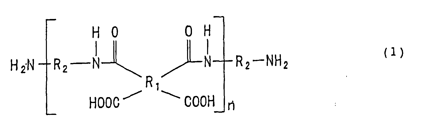 wherein R3 is a tetravalent aromatic residue, and R4 is a hydrogen atom or an alkyl group.
- A production method for a substrate for a flexible print wiring board as set forth in claim 1 or 2, wherein the polyimide-based resin precursor (B) comprises a polyamic acid, a trialkylamine derivative of the polyamic acid, or a mixture of the polyamic acid and the trialkylamine derivative, wherein the polyimide-based resin precursor (A) comprises a polyamic acid, a trialkylamine derivative of the polyamic acid, or a mixture of the polyamic acid and the trialkylamine derivative, and has a greater trialkylamine content than the polyimide-based resin precursor (B).
- A production method for a substrate for a flexible print wiring board, the method comprising: applying a polyimide-based resin precursor solution directly on an electrically conducting material to form a polyimide-based resin precursor layer; and thermalcuring the polyimide-based resin precursor layer for production of a flexible print wiring substrate having a polyimide-based resin layer; wherein a solution of a polyimide-based resin precursor (B) comprising a polyamic acid, or a salt or a mixture of a diamine represented by the following structural formula (1) and pyromellitic acid or biphenyl-3,4,3',4'- tetracarboxylic acid is applied directly on the electrically conducting material; wherein a solution of a polyimide-based resin precursor (A) comprising a polyamic acid, or a salt or a mixture of a diamine represented by the following structural formula (1) and pyromellitic acid or biphenyl-3,4,3',4'-tetracarboxylic acid and containing pyromellitic acid or biphenyl-3,4,3',4'- tetracarboxylic acid in a greater amount than the polyimide-based resin precursor (B) is applied on a layer of the polyimide-based resin precursor (B).wherein R1 is a tetravalent aromatic residue, R2 is a divalent aromatic residue, and n is a real number not smaller than one which represents an average number.

- A production method for a substrate for a flexible print wiring board, the method comprising: applying a polyimide-based resin precursor solution directly on an electrically conducting material to form a polyimide-based resin precursor layer; and thermalcuring the polyimide-based resin precursor layer for production of a flexible print wiring substrate having a polyimide-based resin layer; wherein a solution of a polyimide-based resin precursor (B) comprising a polyamic acid, a triethylamine derivative of the polyamic acid or a mixture of the polyamic acid and the triethylamine derivative is applied directly on the electrically conducting material; wherein a solution of a polyimide-based resin precursor (A) comprising a polyamic acid, a triethylamine derivative of the polyamic acid or a mixture of the polyamic acid and the triethylamine derivative and containing triethylamine in a greater amount than the polyimide-based resin precursor (B) is applied on a layer of the polyimide-based resin precursor (B).
- A substrate for a flexible print wiring board produced by a production method as recited in any of claims 1 to 6.
- A substrate for a flexible print wiring board produced by a production method as recited in claim 7 or 8.
Applications Claiming Priority (5)
| Application Number | Priority Date | Filing Date | Title |
|---|---|---|---|
| JP2000180659 | 2000-06-16 | ||
| JP2000180659 | 2000-06-16 | ||
| JP2001077370 | 2001-03-19 | ||
| JP2001077370 | 2001-03-19 | ||
| PCT/JP2001/004926 WO2001097578A1 (en) | 2000-06-16 | 2001-06-11 | Method for preparing substrate for flexible print wiring board and substrate for flexible print wiring board |
Publications (2)
| Publication Number | Publication Date |
|---|---|
| EP1292177A1 true EP1292177A1 (en) | 2003-03-12 |
| EP1292177A4 EP1292177A4 (en) | 2004-04-21 |
Family
ID=26594045
Family Applications (1)
| Application Number | Title | Priority Date | Filing Date |
|---|---|---|---|
| EP01936955A Withdrawn EP1292177A4 (en) | 2000-06-16 | 2001-06-11 | Method for preparing substrate for flexible print wiring board and substrate for flexible print wiring board |
Country Status (6)
| Country | Link |
|---|---|
| US (1) | US6962726B2 (en) |
| EP (1) | EP1292177A4 (en) |
| JP (1) | JP4841103B2 (en) |
| KR (1) | KR100820221B1 (en) |
| TW (1) | TW521542B (en) |
| WO (1) | WO2001097578A1 (en) |
Cited By (2)
| Publication number | Priority date | Publication date | Assignee | Title |
|---|---|---|---|---|
| CN104854722A (en) * | 2012-11-30 | 2015-08-19 | 株式会社Lg化学 | Organic light-emitting device including flexible substrate and manufacturing method thereof |
| CN105024016A (en) * | 2014-04-29 | 2015-11-04 | Tcl集团股份有限公司 | Flexible substrate, flexible display and manufacturing method thereof |
Families Citing this family (10)
| Publication number | Priority date | Publication date | Assignee | Title |
|---|---|---|---|---|
| US7037637B2 (en) * | 2002-07-17 | 2006-05-02 | Nitto Denko Corporation | Photosensitive polyimide resin precursor composition, optical polyimide obtained from the composition, optical waveguide using the polyimide, and process for producing the optical waveguide |
| TW200520640A (en) * | 2003-09-10 | 2005-06-16 | Nippon Kayaku Kk | Sheet for flexible printed circuit board and method for manufacture thereof |
| JP4734837B2 (en) * | 2004-03-23 | 2011-07-27 | 宇部興産株式会社 | Polyimide film with improved adhesiveness, method for producing the same, and laminate |
| US20090056981A1 (en) * | 2005-04-18 | 2009-03-05 | Toyo Boseki Kabushiki Kaisha | Thin film-laminated polyimide film and flexible printed wiring board |
| WO2006114902A1 (en) * | 2005-04-20 | 2006-11-02 | Toyo Boseki Kabushiki Kaisha | Adhesive sheet, metal-laminated sheet and printed wiring board |
| CN100588309C (en) | 2005-10-05 | 2010-02-03 | 日矿金属株式会社 | Two-Layer Flexible Substrate |
| US20070149001A1 (en) * | 2005-12-22 | 2007-06-28 | Uka Harshad K | Flexible circuit |
| KR100839760B1 (en) * | 2006-02-06 | 2008-06-19 | 주식회사 엘지화학 | Copper Clad Laminates for Chip on Film |
| US20130244000A1 (en) * | 2008-02-05 | 2013-09-19 | E I Du Pont De Nemours And Company | Highly adhesive polyimide copper clad laminate and method of making the same |
| JP5165047B2 (en) | 2010-11-12 | 2013-03-21 | 株式会社有沢製作所 | Polyimide precursor resin solution |
Family Cites Families (14)
| Publication number | Priority date | Publication date | Assignee | Title |
|---|---|---|---|---|
| US3486934A (en) * | 1966-08-01 | 1969-12-30 | Minnesota Mining & Mfg | Process for the production of a metal-polyimide composite and the resulting article |
| US3476705A (en) * | 1966-08-23 | 1969-11-04 | Minnesota Mining & Mfg | Polyamide-acid polymers and polyimides prepared from azobenzene tetracarboxylic dianhydrides |
| DE3566483D1 (en) * | 1984-06-30 | 1988-12-29 | Akzo Gmbh | Flexible polyimide multilayer laminate |
| JPH0632351B2 (en) * | 1986-05-30 | 1994-04-27 | 日東電工株式会社 | Flexible printed circuit board |
| US4937133A (en) | 1988-03-28 | 1990-06-26 | Nippon Steel Chemical Co., Ltd. | Flexible base materials for printed circuits |
| JPH01245586A (en) * | 1988-03-28 | 1989-09-29 | Nippon Steel Chem Co Ltd | flexible printed circuit board |
| JP2804304B2 (en) * | 1989-08-23 | 1998-09-24 | 住友ベークライト株式会社 | Manufacturing method of flexible printed circuit board |
| JP2738453B2 (en) * | 1989-10-03 | 1998-04-08 | 新日鐵化学株式会社 | Manufacturing method of copper clad laminate |
| US5137751A (en) * | 1990-03-09 | 1992-08-11 | Amoco Corporation | Process for making thick multilayers of polyimide |
| JP2958051B2 (en) * | 1990-05-29 | 1999-10-06 | 住友ベークライト株式会社 | Flexible printed circuit board and method of manufacturing the same |
| JPH0513902A (en) | 1990-09-04 | 1993-01-22 | Chisso Corp | Elexible printed substrate and manufacture thereof |
| JPH04262593A (en) * | 1991-02-18 | 1992-09-17 | Hitachi Ltd | Multilayer interconnection structure and multilayers laminating method therefor |
| US6160081A (en) * | 1997-10-31 | 2000-12-12 | Nippon Zeon Co., Ltd. | Photosensitive polyimide resin composition |
| JP2000022288A (en) * | 1998-06-29 | 2000-01-21 | Sony Chem Corp | Flexible printed circuit board and method of manufacturing the same |
-
2001
- 2001-06-11 WO PCT/JP2001/004926 patent/WO2001097578A1/en not_active Ceased
- 2001-06-11 EP EP01936955A patent/EP1292177A4/en not_active Withdrawn
- 2001-06-11 JP JP2002511159A patent/JP4841103B2/en not_active Expired - Fee Related
- 2001-06-11 KR KR1020027014700A patent/KR100820221B1/en not_active Expired - Fee Related
- 2001-06-11 US US10/258,057 patent/US6962726B2/en not_active Expired - Fee Related
- 2001-06-12 TW TW90114118A patent/TW521542B/en not_active IP Right Cessation
Cited By (3)
| Publication number | Priority date | Publication date | Assignee | Title |
|---|---|---|---|---|
| CN104854722A (en) * | 2012-11-30 | 2015-08-19 | 株式会社Lg化学 | Organic light-emitting device including flexible substrate and manufacturing method thereof |
| CN105024016A (en) * | 2014-04-29 | 2015-11-04 | Tcl集团股份有限公司 | Flexible substrate, flexible display and manufacturing method thereof |
| CN105024016B (en) * | 2014-04-29 | 2018-06-19 | Tcl集团股份有限公司 | A kind of flexible base board, flexible display and preparation method thereof |
Also Published As
| Publication number | Publication date |
|---|---|
| US20030108748A1 (en) | 2003-06-12 |
| WO2001097578A1 (en) | 2001-12-20 |
| JP4841103B2 (en) | 2011-12-21 |
| KR20030007571A (en) | 2003-01-23 |
| EP1292177A4 (en) | 2004-04-21 |
| TW521542B (en) | 2003-02-21 |
| KR100820221B1 (en) | 2008-04-07 |
| US6962726B2 (en) | 2005-11-08 |
Similar Documents
| Publication | Publication Date | Title |
|---|---|---|
| JP4755264B2 (en) | Polyimide film and method for producing the same | |
| JPH01245586A (en) | flexible printed circuit board | |
| KR100668948B1 (en) | Metal Laminate and Method of Manufacturing the Same | |
| JP2746555B2 (en) | Flexible printed circuit board | |
| JP7714391B2 (en) | Polyamic acid, polyimide, polyimide film, metal-clad laminate and circuit board | |
| JP7212515B2 (en) | Metal-clad laminates and circuit boards | |
| US6962726B2 (en) | Method for preparing substrate for flexible print wiring board, and substrate for flexible print wiring board | |
| US8034460B2 (en) | Metallic laminate and method of manufacturing the same | |
| JPWO2001097578A1 (en) | Manufacturing method of substrate for flexible printed wiring board and substrate for flexible printed wiring board | |
| CN101296757B (en) | Flexible laminated board, manufacturing method thereof, and flexible printed circuit board | |
| CN100505980C (en) | Substrate for flexible printed wiring board and method for manufacturing same | |
| JP7465060B2 (en) | Metal-clad laminates and circuit boards | |
| JP4571043B2 (en) | Laminated body and method for producing the same | |
| JPS63264632A (en) | Low-thermal expansion resin | |
| JP2023051810A (en) | Metal-clad laminates, circuit boards, electronic devices and electronic equipment | |
| JPH0955567A (en) | Flexible printed wiring board manufacturing method | |
| JP4615401B2 (en) | Laminated body | |
| JP4694142B2 (en) | Manufacturing method of substrate for flexible printed wiring board | |
| JP4936729B2 (en) | Flexible printed wiring board substrate and manufacturing method thereof | |
| JP2005329641A (en) | Substrate for flexible printed circuit board and its production method | |
| JP2000101205A (en) | Metal-clad laminate and flexible printed wiring board using the same | |
| JP2025102511A (en) | Copper-clad laminates, circuit boards, electronic devices and electronic equipment | |
| JP2024046788A (en) | Circuit board manufacturing method | |
| JPH0760935B2 (en) | Flexible printed circuit board manufacturing method | |
| JP2007168123A (en) | Flexible substrate with metal foil |
Legal Events
| Date | Code | Title | Description |
|---|---|---|---|
| PUAI | Public reference made under article 153(3) epc to a published international application that has entered the european phase |
Free format text: ORIGINAL CODE: 0009012 |
|
| 17P | Request for examination filed |
Effective date: 20021017 |
|
| AK | Designated contracting states |
Kind code of ref document: A1 Designated state(s): AT BE CH CY DE DK ES FI FR GB GR IE IT LI LU MC NL PT SE TR Designated state(s): AT BE CH CY DE DK ES FI FR GB GR IE IT LI LU MC NL PT SE TR |
|
| A4 | Supplementary search report drawn up and despatched |
Effective date: 20040310 |
|
| RIC1 | Information provided on ipc code assigned before grant |
Ipc: 7C 08J 5/24 B Ipc: 7B 32B 27/34 B Ipc: 7H 05K 1/03 B Ipc: 7H 05K 3/00 A |
|
| RBV | Designated contracting states (corrected) |
Designated state(s): DE FR GB |
|
| 17Q | First examination report despatched |
Effective date: 20080211 |
|
| STAA | Information on the status of an ep patent application or granted ep patent |
Free format text: STATUS: THE APPLICATION IS DEEMED TO BE WITHDRAWN |
|
| 18D | Application deemed to be withdrawn |
Effective date: 20101110 |