EP1292011A2 - Motor control for reducing high harmonic currents - Google Patents
Motor control for reducing high harmonic currents Download PDFInfo
- Publication number
- EP1292011A2 EP1292011A2 EP02018593A EP02018593A EP1292011A2 EP 1292011 A2 EP1292011 A2 EP 1292011A2 EP 02018593 A EP02018593 A EP 02018593A EP 02018593 A EP02018593 A EP 02018593A EP 1292011 A2 EP1292011 A2 EP 1292011A2
- Authority
- EP
- European Patent Office
- Prior art keywords
- motor
- axis
- higher harmonic
- current
- coordinate system
- Prior art date
- Legal status (The legal status is an assumption and is not a legal conclusion. Google has not performed a legal analysis and makes no representation as to the accuracy of the status listed.)
- Granted
Links
Images


Classifications
-
- H—ELECTRICITY
- H02—GENERATION; CONVERSION OR DISTRIBUTION OF ELECTRIC POWER
- H02P—CONTROL OR REGULATION OF ELECTRIC MOTORS, ELECTRIC GENERATORS OR DYNAMO-ELECTRIC CONVERTERS; CONTROLLING TRANSFORMERS, REACTORS OR CHOKE COILS
- H02P6/00—Arrangements for controlling synchronous motors or other dynamo-electric motors using electronic commutation dependent on the rotor position; Electronic commutators therefor
- H02P6/10—Arrangements for controlling torque ripple, e.g. providing reduced torque ripple
-
- H—ELECTRICITY
- H02—GENERATION; CONVERSION OR DISTRIBUTION OF ELECTRIC POWER
- H02P—CONTROL OR REGULATION OF ELECTRIC MOTORS, ELECTRIC GENERATORS OR DYNAMO-ELECTRIC CONVERTERS; CONTROLLING TRANSFORMERS, REACTORS OR CHOKE COILS
- H02P21/00—Arrangements or methods for the control of electric machines by vector control, e.g. by control of field orientation
- H02P21/22—Current control, e.g. using a current control loop
Definitions
- the present invention relates to a motor control apparatus and motor control method, and more specifically, it relates to an apparatus of and method for controlling a motor to reduce the higher harmonic current flowing to a 3-phase AC motor.
- the applicant of the present invention has proposed a motor control apparatus that reduces the higher harmonic current flowing to a 3-phase AC motor (Japanese Patent Application No. 2000-356117).
- This motor control apparatus includes a fundamental current control system that controls a fundamental current in a dq-axis orthogonal coordinate system rotating in synchronization with the rotation of the 3-phase AC motor and a higher harmonic current control system that controls a higher harmonic current in a dhqh-axis orthogonal coordinate system (a higher harmonic coordinate system) rotating at a frequency that is an integral multiple of the frequency of the fundamental component of the motor current.
- the fundamental current is a direct current and the higher harmonic current is an alternating current in the dq-axis coordinate system in this motor control apparatus.
- the higher harmonic current manifesting as the alternating current quantity is extracted from the current in the dq-axis coordinate system by using a high pass filter and the extracted current is converted to a higher harmonic current in the dhqh-axis higher harmonic coordinate system so as to handle the higher harmonic current as the quantity of direct current.
- a PI control circuit is employed in the higher harmonic current control system to realize higher harmonic current control with minimum control deviation.
- the higher harmonic current control system cannot achieve quick response simply by providing the PI control circuit in the higher harmonic current control system and, consequently, there is a problem in that the higher harmonic current cannot be reduced to a sufficient degree.
- the motor control apparatus comprises a fundamental current control means for controlling a fundamental current in a 3-phase AC motor in an orthogonal coordinate system constituted of a d-axis and a q-axis (hereafter referred to as a dq-axis coordinate system) rotating in synchronization with the rotation of the 3-phase AC motor, a higher harmonic current control means for controlling a higher harmonic current in the motor in an orthogonal coordinate system constituted of a dh axis and a qh axis (hereafter referred to as a dhqh-axis coordinate system) rotating at a frequency that is an integral multiple of the frequency of the fundamental component of the current flowing to the motor, an estimation means for estimating the level of the harmonic speed electromotive force in the motor in the dhqh-axis coordinate system and a compensation means for compensating the harmonic speed electromotive force estimated by the estimation means.
- a fundamental current control means for controlling a fundamental current in a 3-phase AC motor in an orthogonal coordinate system
- a harmonic speed electromotive force in the motor in the dhqh-axis coordinate system is estimated and the estimated harmonic speed electromotive force is compensated.
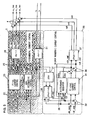
- FIG. 1 illustrates the structure adopted in the motor control apparatus in the first embodiment.
- the motor control apparatus in the embodiment implements vector control through which a torque control performance level comparable to that of control on a DC motor is achieved even when a 3-phase AC motor is used.
- a motor M in the embodiment is a permanent magnet 3-phase synchronous motor.
- a torque control circuit 1 calculates a d-axis fundamental current command value id_cmd and a q-axis fundamental current command value iq_cmd in a dq-axis coordinate system by using a current command value table (not shown) based upon a torque command value Te_cmd and an electrical rotation speed ⁇ (to be detailed later) of the 3-phase synchronous motor M.
- the dq-axis coordinate system is an orthogonal coordinate system constituted of a d-axis and a q-axis, rotating at an electrical rotation speed which is an integral multiple of the mechanical rotation speed of the 3-phase synchronous motor M.
- the dq-axis coordinate system rotates in synchronization with the motor rotation.
- a fundamental current control circuit 2 controls a fundamental current in the dq-axis coordinate system. While further details are to be provided later, the fundamental current control circuit 2 converts actual currents iu and iv in the 3-phase synchronous motor M to actual currents id and iq along the d-axis and the q-axis respectively and calculates fundamental voltage command values vu_tmp0, vv_tmp0 and vq_tmp0 to be used to match the d-axis actual current id and the q-axis actual current iq with the fundamental current command values id_cmd and iq_cmd respectively.
- a higher harmonic current control circuit 3 controls a higher harmonic current in a dhqh-axis higher harmonic coordinate system.
- the dhqh-axis higher harmonic coordinate system is an orthogonal coordinate system constituted of a dh-axis and a qh-axis, rotating at a frequency that is an integral multiple of the frequency of the fundamental components of the currents flowing to the 3-phase synchronous motor M.
- the higher harmonic current control circuit 3 extracts higher harmonic components idh and iqh in the dhqh-axis higher harmonic coordinate system from the d-axis actual current id and the q-axis actual current iq and calculates higher harmonic voltage command values vuh, vvh and vwh to be used to match the dh-axis higher harmonic current idh and the qh-axis higher harmonic current iqh with higher harmonic current command values idh_cmd and iqh_cmd respectively.
- An adder 4 adds the higher harmonic voltage command values vuh, vvh and vwh obtained at the higher harmonic current control circuit 3 respectively to the fundamental voltage command values vu_tmp0, vv_tmp0 and vw_tmp0 obtained at the fundamental current control circuit 2, to calculate 3-phase AC voltage command values vu_tmp, vv_tmp and vw_tmp.
- a power conversion circuit 5 is an invertor constituted of a power conversion element such as an IGBT.
- the power conversion circuit 5 switches a DC voltage from a DC source (not shown) which may be a battery in conformance to the 3-phase voltage command values vu_tmp, vv_tmp and vw_tmp to generate 3-phase AC voltages U, V and W and then applies the 3-phase AC voltages thus generated to the 3-phase AC motor M.
- a DC source not shown
- the power conversion circuit 5 switches a DC voltage from a DC source (not shown) which may be a battery in conformance to the 3-phase voltage command values vu_tmp, vv_tmp and vw_tmp to generate 3-phase AC voltages U, V and W and then applies the 3-phase AC voltages thus generated to the 3-phase AC motor M.
- An encoder PS which is connected to the 3-phase synchronous motor M, detects the rotational position ⁇ m of the motor M.
- a current sensor 6 detects the actual current iu at a U-phase and the actual current iv at a V-phase in the 3-phase synchronous motor M.
- a phase speed calculating circuit 7 calculates the electrical rotation speed (angular speed) ⁇ which is an integral multiple of the mechanical rotation speed (angular speed) ⁇ m of the 3-phase synchronous motor M and also calculates an electrical rotational phase ⁇ , based upon a motor rotational position signal ⁇ m provided by the encoder PS. It is to be noted that the electrical rotation speed (angular speed) ⁇ indicates the frequency (angular frequency) of the AC currents flowing to the 3-phase synchronous motor M.
- FIG. 2 shows in detail the structures adopted in the fundamental current control circuit 2 and the higher harmonic current control circuit 3 in the first embodiment.
- a circuit for compensating the harmonic speed electromotive force at the motor M is added in conjunction with the fundamental current control circuit 2 and the higher harmonic current control circuit 3.
- the fundamental current control circuit 2 includes a 3-phase/dq conversion circuit 21, a subtractor 22, a PI-dq current control circuit 23, a non-interactive control circuit 24, an adder 25 and a dq/3-phase conversion circuit 26.
- the 3-phase/dq conversion circuit 21 converts the actual currents iu and iv flowing in the 3-phase synchronous motor detected by the current sensor 6 to the d-axis actual current id and the q-axis actual current iq respectively.
- the subtractor 22 calculates the deviations (id_cmd - id, iq_cmd - iq) by subtracting the actual currents id and iq from the d-axis current command value id_cmd and the q-axis current command value iq_cmd respectively.
- the PI-dq current control circuit 23 calculates a d-axis voltage command value and a q-axis voltage command value by implementing a PI (proportional integral) control for the fundamental current deviations (id_cmd - id) and (iq_cmd - iq).
- the non-interactive control circuit 24 which improves the response of the d-axis current and the q-axis current by compensating the speed electromotive force in the dq-axis coordinate system, calculates a d-axis compensating voltage vd_cmp and a q-axis compensating voltage vq_cmp for compensating the speed electromotive force in the dq-axis coordinate system.
- the adder 25 adds the d-axis compensating voltage vd_cmp and the q-axis compensating voltage vq_cmp respectively to the d-axis voltage command value and the q-axis voltage command value output from the PI-dq current control circuit 23, to calculate a d-axis voltage command value vd_cmd and a q-axis voltage command value vq_cmd.
- the dq/3-phase conversion circuit 26 converts the d-axis voltage command value vd_cmd and the q-axis voltage command value vq_cmd to the U-phase fundamental voltage command value vu_tmp0, the V-phase fundamental voltage command value vv_tmp0 and the W-phase fundamental voltage command value vw_tmp0 in a 3-phase AC coordinate system.
- the higher harmonic current control circuit 3 includes a high pass filter 31, a dq/dhqh conversion circuit 32, a subtractor 33, a PI-dhqh current control circuit 34, a harmonic speed electromotive force estimating circuit 35, an adder 36 and a dhqh/3-phase conversion circuit 37.
- the high pass filter 31 extracts the higher harmonic components of the current flowing to the motor M by filtering the d-axis actual current id and the q-axis current iq obtained at the 3-phase/dq conversion circuit 21.
- the dq/dhqh conversion circuit 32 converts the higher harmonic currents extracted by the high pass filter 31 to a dh-axis higher harmonic current idh and a qh-axis higher harmonic current iqh.
- the subtractor 33 calculates the deviations (idh_cmd - idh) and (iqh_cmd - iqh) by subtracting the dh-axis higher harmonic current idh and the qh-axis higher harmonic current iqh from the dh-axis current command value idh_cmd and the qh-axis current command value iqh_cmd respectively.
- the PI-dhqh current control circuit 34 calculates a dh-axis voltage command value and a qh-axis voltage command value by implementing a PI (proportional integral) control for the higher harmonic current deviations (idh_cmd - idh) and (iqh_cmd - iqh).
- the harmonic speed electromotive force estimating circuit 35 calculates a dh-axis harmonic speed electromotive force Kdhw and a qh-axis harmonic speed electromotive force Kqhw in order to improve the response of the dh-axis current and the qh-axis current by compensating the speed electromotive force in the dhqh-axis higher harmonic coordinate system.
- the method to be adopted to calculate the dh-axis harmonic speed electromotive force Kdhw and the qh-axis harmonic speed electromotive force Kqhw is to be detailed later.
- the adder 36 adds the dh-axis harmonic speed electromotive force Kdhw and the qh-axis harmonic speed electromotive force Kqhw respectively to the dh-axis voltage command value and the qh-axis voltage command value output from the PI-dhqh current control circuit 34 to calculate a dh-axis voltage command value vdh_cmd and a qh-axis voltage command value vqh_cmd.
- the dhqh/3-phase conversion circuit 37 converts the dh-axis voltage command value vdh_cmd and the qh-axis voltage command value vqh_cmd to the U-phase higher harmonic voltage command value vuh, the V-phase higher harmonic voltage command value vvh and the W-phase higher harmonic voltage command value vwh in the 3-phase AC coordinate system.
- the adder 4 adds the fundamental voltage command values vu_tmp0, vv_tmp0 and vw_tmp0 obtained at the fundamental current control circuit 2 respectively with the higher harmonic voltage command values vuh, vvh and vwh obtained at the higher harmonic current control circuit 3 for the individual phases to calculate the 3-phase AC voltage command values vu_tmp, vv_tmp and vw_tmp.
- the higher harmonic component of the inductance which causes the harmonic speed electromotive force is constituted of the spatial harmonic components of the self inductances at the U phase, the V phase and the W phase, which are expressed as 3-phase AC circuit equations.
- the self inductances Lu, Lv and Lw at the U phase, the V phase and the W phase are expressed as in (1) below.
- Lg0 represents the DC component of the inductance in the 3-phase synchronous motor M
- Ln (n 1, 2, ...
- edk represents the d-axis higher harmonic component in the speed electromotive force attributable to the magnetic flux of the permanent magnet
- eqk represents the q-axis higher harmonic component in the speed electromotive force attributable to the magnetic flux of the permanent magnet.
- the term constituted of the product of ⁇ , which is seen in the third column of expression (2), represents the harmonic speed electromotive force attributable to the higher harmonic components in the inductances.
- the circuit equation in the dhqh-axis higher harmonic coordinate system is expressed as in (5) below.
- ⁇ 5 represents the higher harmonic component of the fifth order in the magnetic flux of the permanent magnet.
- vdh and vqh represent the dh-axis voltage and the qh-axis voltage respectively.
- ed0 and eq0 represent speed electromotive forces obtained by converting the fundamental component ⁇ of the speed electromotive force attributable to the magnetic flux of the permanent magnet in the dq-axis coordinate system to values in the dhqh-axis coordinate system.
- edh and eqh represent harmonic speed electromotive forces obtained by converting the harmonic speed electromotive forces edk and eqk attributable to the magnetic flux of the permanent magnet in the dq-axis coordinate system to values in the dhqh-axis coordinate system.
- edh and eqh can be expressed as in (6) below when the higher harmonic components of the magnetic flux of the permanent magnet are expressed as in (4).
- the dq-axis values can be converted to values in a coordinate system corresponding to the rotation of any higher harmonic current component among the higher harmonic current components contained in the motor current.
- the term of the harmonic speed electromotive force constituting the cause for the generation of the higher harmonic current is expressed as a direct current quantity.
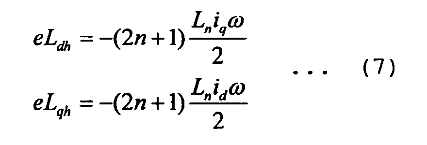
- the harmonic speed electromotive force estimating circuit 35 ascertains a dh-axis component eLdh and a qh-axis component eLqh of the harmonic speed electromotive force attributable to the higher harmonic components in the inductances in the motor M based upon expression (5).
- the harmonic speed electromotive forces eLdh and eLqh attributable to the motor inductance higher harmonic components can be calculated as in (7) below based upon the order n of the motor inductance and the values of the components of that order (the motor inductance higher harmonic component), the d-axis fundamental current id and the q-axis fundamental current iq that have been detected and the electrical rotation speed ⁇ of the motor M.
- Ln since the motor inductance also changes in correspondence to the motor current value, Ln may be handled as a variable instead of a constant by referencing a table prepared in advance for an appropriate value or by expressing Ln as a function of the current.
- harmonic speed electromotive forces edh and eqh attributable to the higher harmonic component in the magnetic flux of the permanent magnet are expressed as in (6) as explained earlier.
- the estimated harmonic speed electromotive force values Kdhw and Kqhw, respectively representing the sums of the harmonic speed electromotive forces edh and eqh attributable to the higher harmonic components in the magnetic flux of the permanent magnet expressed in (6) and the harmonic speed electromotive forces eLdh and eLqh attributable to the higher harmonic components in the motor inductances expressed in (7), are calculated through the formulae in (8) below.
- Kdhw edh + eLdh
- Kqhw eqh + eLqh
- the adder 36 shown in FIG. 2 adds harmonic speed electromotive force values Kdhw and Kqhw thus calculated to the output obtained by implementing the PI control on the dh-axis higher harmonic current and the qh-axis higher harmonic current, i.e., the output from the PI-dhqh current control circuit 34, to calculate the dh-axis voltage command value vdh_cmd and the qh-axis voltage command value vqh_cmd through the formulae in (9) below.
- Kpdh, Kpqh, Kidh and Kiqh each represent a constant used in the PI (proportional integral) operation control in the PI-dhqh current control circuit 34.
- Kpdh and Kpqh are the proportional constants along the dh-axis and the qh-axis respectively
- Kidh and Kiqh are the integral constants along the dh-axis and the qh-axis respectively.
- both the harmonic speed electromotive forces attributable to the higher harmonic component in the magnetic flux of the permanent magnet and the harmonic speed electromotive forces attributable to the motor inductances higher harmonic components are estimated.
- the effect of the harmonic speed electromotive forces attributable to the motor inductances higher harmonic components is insignificant but the harmonic speed electromotive forces attributable to the higher harmonic components in the magnetic flux of the permanent magnet is significant, only the harmonic speed electromotive forces attributable to the higher harmonic components in the magnetic flux of the permanent magnet expressed in (6) needs to be compensated.
- the effect of the harmonic speed electromotive forces attributable to the higher harmonic components in the magnetic flux of the permanent magnet is not significant but harmonic speed electromotive forces attributable to the motor inductance higher harmonic component is significant, only the harmonic speed electromotive forces attributable to the motor inductance higher harmonic component expressed in (7) needs to be compensated. In either of these cases, the harmonic speed electromotive force can be effectively compensated through a simple structure.
- FIG. 3 presents the results of a simulation of the higher harmonic current control achieved in the embodiment.
- the results presented in FIG. 3 were obtained through a simulation conducted by implementing control of higher harmonic currents of the fifth order, i.e., by setting the current command values for the higher harmonic currents of the fifth order to 0.
- a comparison of the higher harmonic current control in the related art implemented without any harmonic speed electromotive force compensation and the higher harmonic current control achieved in the first embodiment by compensating the harmonic speed electromotive force reveals that compared to the control implemented in the related art, the control in the first embodiment greatly reduces the length of time elapsing between the control start and control convergence.
- higher harmonic current control with quick response is realized and a highly efficient motor current control system can be realized through accurate control of the higher harmonic currents.
- the harmonic speed electromotive forces in the motor M in the dhqh-axis higher harmonic coordinate system is estimated and the estimated harmonic speed electromotive forces are compensated.
- the harmonic speed electromotive forces which cause a disturbance to the higher harmonic current control is compensated to improve the response of the higher harmonic current control system and, as a result, more efficient and higher performance drive control of the 3-phase synchronous motor M is realized by reducing the higher harmonic currents.
- the higher harmonic voltage command values vdh_cmd and vqh_cmd in the dhqh-axis higher harmonic coordinate system are first converted to the voltage command values vuh, vvh and vwh in the 3-phase AC coordinate system and then the voltage command values vu_tmp, vv_tmp and vw_tmp in the 3-phase AC coordinate system are calculated by adding the voltage command values vu_tmp0, vv_tmp0 and vw_tmp0 output from the fundamental current control circuit 2 to the voltage command values vuh, vvh and vwh.
- the voltage command values vu_tmp, vv_tmp and vw_tmp in the 3-phase AC coordinate system may instead be calculated through dq/3-phase conversion after adding the higher harmonic voltage command values vdh_cmd and vqh_cmd in the dhqh-axis higher harmonic coordinate system to the fundamental voltage command values vd_cmd and vq_cmd in the dq-axis coordinate system.
- the higher harmonic voltage command values vdh_cmd and vqh_cmd in the dhqh-axis higher harmonic coordinate system may first be converted to higher harmonic voltage command values in an ⁇ axis coordinate system, the converted command values may be added with an ⁇ -axis fundamental voltage command value and a ⁇ -axis fundamental voltage command value and the sums may be converted to values in the 3-phase AC coordinate system to calculate 3-phase AC voltage command values.
- FIG. 4 shows in detail the structures assumed in the fundamental current control circuit 2 and a higher harmonic current control circuit 3A in the second embodiment. It is to be noted that since the overall structure of the motor control apparatus achieved in the second embodiment is similar to the structure shown in FIG. 1, its illustration and explanation are omitted. In addition, the same reference numerals are assigned to components similar to those in FIG. 2 to focus on an explanation of the features that differentiate the second embodiment.
- the d-axis actual current id and the q-axis actual current iq are input to the harmonic speed electromotive force estimating circuit 35 in the first embodiment
- the d-axis current command value id_cmd and the q-axis current command value iq_cmd are input to the harmonic speed electromotive force estimating circuit 35A in the second embodiment.
- the harmonic speed electromotive forces eLdh and eLqh attributable to the higher harmonic components in the inductances can be estimated with a higher degree of accuracy.
- the cycle of the arithmetic operation for estimating the harmonic speed electromotive forces becomes longer than the cycle of the current control.
- the harmonic speed electromotive force values Kdhw and Kqhw can be estimated without having to increase the volume of the arithmetic operation performed in the current control cycle.
- FIG. 5 shows in detail the structures assumed in the fundamental current control circuit 2 and a higher harmonic current control circuit 3B in the third embodiment. It is to be noted that since the overall structure of the motor control apparatus achieved in the third embodiment is similar to the structure shown in FIG. 1, its illustration and explanation are omitted. In addition, the same reference numerals are assigned to components similar to those in FIG. 2 to focus on an explanation of the features that differentiate the third embodiment.
- the harmonic speed electromotive force estimating circuit 35 is employed to estimate the harmonic speed electromotive force values Kdhw and Kqhw.
- a disturbance observer 38 is employed in place of the harmonic speed electromotive force estimating circuit 35 to estimate the harmonic speed electromotive force values Kdhw and Kqhw.
- FIG. 6 shows the structure adopted in the disturbance observer 38.
- the dh-axis higher harmonic current idh and the qh-axis higher harmonic current iqh, the dh-axis higher harmonic voltage command value vdh_cmd and the qh-axis higher harmonic voltage command value vqh_cmd are input to the disturbance observer 38.
- Inverse systems 38a and 38b of the plant (the control target, i.e., the 3-phase synchronous motor M) to be used in the disturbance observer 38 are achieved through approximation based upon the resistance R and the inductance Lg0 of the motor M representing the typical characteristics in the circuit equation (5).
- the harmonic speed electromotive force values Kdhw and Kqhw estimated by the disturbance observer 38 By adding the harmonic speed electromotive force values Kdhw and Kqhw estimated by the disturbance observer 38 to the dh-axis higher harmonic voltage command value and the qh-axis higher harmonic voltage command value output by the PI-dhqh current control circuit 34, the adverse effect of the harmonic speed electromotive force can be reduced.
- the harmonic speed electromotive force can be estimated and compensated even when the higher harmonic components of the motor inductances are not known or when they change, or even when the higher harmonic component in the magnetic flux of the permanent magnet are not known.
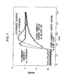
- FIG. 7 presents the results of a simulation of the higher harmonic current control achieved in the third embodiment.
- FIG. 7 shows the results of a simulation of control implemented on a fifth-order higher harmonic current contained in the motor current.
- the fifth-order higher harmonic current command value is set to 0. While the point in time at which convergence occurs varies in correspondence to the pole ⁇ c of the disturbance observer 38, a comparison of the higher harmonic current control in the related art implemented without compensating the harmonic speed electromotive force and the higher harmonic current control achieved in the third embodiment by compensating the harmonic speed electromotive force reveals that the third embodiment realizes quicker response compared to the prior art.
- an identity observer achieved based upon an equation of state or a finite setting time observer may be utilized.
Landscapes
- Engineering & Computer Science (AREA)
- Power Engineering (AREA)
- Control Of Ac Motors In General (AREA)
- Control Of Motors That Do Not Use Commutators (AREA)
Abstract
Description


Claims (10)
- A motor control apparatus, comprising:a fundamental current control means (2) for controlling a fundamental current in a 3-phase AC motor (M) in an orthogonal coordinate system constituted of a d-axis and a q-axis (hereafter referred to as a dq-axis coordinate system) rotating in synchronization with the rotation of the 3-phase AC motor (M);a higher harmonic current control means (3) for controlling a higher harmonic current in the motor (M) in an orthogonal coordinate system constituted of a dh-axis and a qh-axis (hereafter referred to as a dhqh-axis coordinate system) rotating at a frequency that is an integral multiple of the frequency of a fundamental component of the current flowing to the motor (M);an estimation means (35, 35A, 38) for estimating the harmonic speed electromotive force in the motor (M) in the dhqh-axis coordinate system; anda compensation means (36) for compensating the harmonic speed electromotive force estimated by the estimation means.
- A motor control apparatus according to claim 1, wherein:the higher harmonic current control means (3) outputs a higher harmonic voltage command value to be used to set the higher harmonic current in the dhqh-axis coordinate system to 0; andthe compensation means (36) compensates the harmonic speed electromotive force by adding the estimated value for the harmonic speed electromotive force to the higher harmonic voltage command value.
- A motor control apparatus according to claim 1, wherein:the estimation means (35, 35A, 38) estimates a harmonic speed electromotive force attributable to a higher harmonic component in an inductance of the motor (M).
- Amotor control apparatus according to claim 1, wherein:the 3-phase AC motor (M) is a permanent magnet synchronous motor; andthe estimation means (35, 35A, 38) estimates a harmonic speed electromotive force attributable to a higher harmonic component in the magnetic flux of the permanent magnet in the motor (M).
- Amotor control apparatus according to claim 1, wherein:the 3-phase AC motor (M) is a permanent magnet synchronous motor; andthe estimation means (35, 35A, 38) estimates a harmonic speed electromotive force attributable to a higher harmonic component in the magnetic flux of the permanent magnet in the motor (M) and a higher harmonic component in an inductance of the motor (M).
- A motor control apparatus according to claim 3, wherein:the estimation means (35, 35A, 38) estimates the harmonic speed electromotive force attributable to the inductance of the motor (M) based upon a fundamental current command value of the motor (M) in the dq-axis coordinate system, an electrical rotation speed of the motor (M) and the higher harmonic component in the inductance.
- A motor control apparatus according to claim 3, wherein:the estimation means (35, 35A, 38) estimates the harmonic speed electromotive force attributable to the inductance of the motor (M) based upon a d-axis fundamental current and a q-axis fundamental current in the motor (M), an electrical rotation speed of the motor (M) and the higher harmonic component in the inductance.
- A motor control apparatus according to claim 4, wherein:the estimation means (35, 35A, 38) estimates the harmonic speed electromotive force attributable to the higher harmonic component in the magnetic flux of the permanent magnet in the motor (M) based upon the higher harmonic component in the magnetic flux of the permanent magnet in the motor (M) and an electrical rotation speed of the motor (M) .
- A motor control apparatus according to claim 1, wherein:the estimation means (35, 35A, 38) is a disturbance observer constituted by using a resistance of the motor (M) and a fundamental component of inductances in the motor (M) as a parameter.
- A motor control method adopted in a motor control apparatus having a fundamental current control device (2) that controls a fundamental current in a 3-phase AC motor (M) in an orthogonal coordinate system constituted of a d-axis and a q-axis rotating in synchronization with the rotation of the 3-phase AC motor (M) and a higher harmonic current control device (3) that controls a higher harmonic current in the motor (M) in an orthogonal coordinate system constituted of a dh-axis and a qh-axis (hereafter referred to as a dhqh-axis coordinate system) rotating at a frequency that is an integral multiple of the frequency of a fundamental component of the current flowing to the motor (M), comprising:estimating a harmonic speed electromotive force in the motor (M) in the dhqh-axis coordinate system; andcompensating the estimated harmonic speed electromotive force.
Applications Claiming Priority (2)
| Application Number | Priority Date | Filing Date | Title |
|---|---|---|---|
| JP2001273515 | 2001-09-10 | ||
| JP2001273515A JP3582505B2 (en) | 2001-09-10 | 2001-09-10 | Motor control device |
Publications (3)
| Publication Number | Publication Date |
|---|---|
| EP1292011A2 true EP1292011A2 (en) | 2003-03-12 |
| EP1292011A3 EP1292011A3 (en) | 2005-02-02 |
| EP1292011B1 EP1292011B1 (en) | 2007-10-10 |
Family
ID=19098717
Family Applications (1)
| Application Number | Title | Priority Date | Filing Date |
|---|---|---|---|
| EP02018593A Expired - Lifetime EP1292011B1 (en) | 2001-09-10 | 2002-08-19 | Motor control for reducing high harmonic currents |
Country Status (4)
| Country | Link |
|---|---|
| US (1) | US6727675B2 (en) |
| EP (1) | EP1292011B1 (en) |
| JP (1) | JP3582505B2 (en) |
| DE (1) | DE60222844T2 (en) |
Cited By (9)
| Publication number | Priority date | Publication date | Assignee | Title |
|---|---|---|---|---|
| FR2855678A1 (en) * | 2003-06-02 | 2004-12-03 | Alstom | Electromagnetic torque unit regulation process for polyphase rotating electrical machine e.g. rolling mill driving rotor, involves determining harmonic values of current and/or voltage generated by inverter to set instantaneous torque |
| FR2869171A1 (en) * | 2004-04-14 | 2005-10-21 | Denso Corp | METHOD FOR CONTROLLING THE MAGNETIC SOUND OF AN ALTERNATING CURRENT MACHINE |
| FR2869170A1 (en) * | 2004-04-14 | 2005-10-21 | Denso Corp | METHOD FOR CONTROLLING THE MAGNETIC SOUND OF AN ALTERNATING CURRENT MACHINE |
| EP1467478A3 (en) * | 2003-04-07 | 2005-12-14 | Nissan Motor Co., Ltd. | Motor control apparatus and motor control method |
| US7208903B2 (en) | 2004-09-06 | 2007-04-24 | Toyota Jidosha Kabushiki Kaisha | Control device for alternating-current motor |
| EP2206233A4 (en) * | 2007-10-15 | 2016-04-20 | Unico | BUS DISTURBANCE REGULATOR |
| CN108702116A (en) * | 2016-03-03 | 2018-10-23 | 罗伯特·博世有限公司 | It is pulsed and is reduced by the best torque of current shaping |
| DE102020105630A1 (en) | 2020-03-03 | 2021-09-09 | Dr. Ing. H.C. F. Porsche Aktiengesellschaft | Device and method for influencing electromagnetic forces in an electric traction machine |
| CN115037204A (en) * | 2022-06-17 | 2022-09-09 | 哈尔滨工业大学(威海) | A method for suppressing current harmonics of permanent magnet synchronous motor |
Families Citing this family (24)
| Publication number | Priority date | Publication date | Assignee | Title |
|---|---|---|---|---|
| KR100778190B1 (en) * | 2000-11-09 | 2007-11-22 | 다이킨 고교 가부시키가이샤 | Synchronous motor control method and device |
| JP2003244992A (en) * | 2002-02-21 | 2003-08-29 | Nissan Motor Co Ltd | Current control method for rotating electric machine |
| JP3783695B2 (en) * | 2003-03-20 | 2006-06-07 | 日産自動車株式会社 | Motor control device |
| JP3771544B2 (en) * | 2003-03-24 | 2006-04-26 | 株式会社日立製作所 | Method and apparatus for controlling permanent magnet type synchronous motor |
| US7102305B2 (en) * | 2003-05-22 | 2006-09-05 | Toyoda Koki Kabushiki Kaisha | Apparatus and method for controlling motor |
| JP2005328691A (en) * | 2004-04-15 | 2005-11-24 | Denso Corp | Motor control device |
| JP4926492B2 (en) * | 2006-02-20 | 2012-05-09 | 本田技研工業株式会社 | Motor control device |
| US8080957B2 (en) * | 2006-04-11 | 2011-12-20 | Nsk, Ltd. | Motor control device and motor-driven power steering system using the same |
| US7545113B2 (en) | 2006-10-24 | 2009-06-09 | Unico, Inc. | Harmonic disturbance regulator |
| JP4915305B2 (en) * | 2007-07-16 | 2012-04-11 | 株式会社デンソー | Control device for electric power steering device |
| JP5228436B2 (en) * | 2007-10-18 | 2013-07-03 | 株式会社安川電機 | Motor control device and control method thereof |
| JP5576145B2 (en) * | 2010-02-25 | 2014-08-20 | アスモ株式会社 | Motor control device |
| GB201003456D0 (en) * | 2010-03-02 | 2010-04-14 | Trw Ltd | Current sensor error compensation |
| GB201006404D0 (en) * | 2010-04-16 | 2010-06-02 | Trw Ltd | Motor control with voltage harmonic shaping |
| JP5692572B2 (en) * | 2010-10-31 | 2015-04-01 | 新中 新二 | Synchronous motor drive control device |
| KR101549283B1 (en) * | 2011-10-12 | 2015-09-01 | 엘에스산전 주식회사 | Parameter estimating apparatus for permanent magnet synchronous motor driving system |
| US8981692B2 (en) * | 2012-07-19 | 2015-03-17 | GM Global Technology Operations LLC | Torque ripple reduction of multiple harmonic components |
| JP2014176157A (en) * | 2013-03-07 | 2014-09-22 | Toshiba Corp | Motor rotation position detection device, washer, and method for detecting motor rotation position |
| JP5713044B2 (en) * | 2013-04-15 | 2015-05-07 | ダイキン工業株式会社 | Control device |
| JP6290028B2 (en) * | 2014-07-30 | 2018-03-07 | 株式会社東芝 | Motor control device, air conditioner, washing machine and refrigerator |
| EP3142245B1 (en) * | 2015-09-09 | 2020-12-23 | Skf Magnetic Mechatronics | Electrical installation comprising an electrical apparatus, a three-phase inverter and a control device for controlling the inverter, and related method |
| US9729099B1 (en) | 2016-05-19 | 2017-08-08 | Nxp Usa, Inc. | Sensorless control of AC induction motor method and apparatus |
| JP6848622B2 (en) * | 2017-04-05 | 2021-03-24 | 富士電機株式会社 | Power converter and its control device |
| CN113258841B (en) * | 2021-06-23 | 2021-09-24 | 深圳市杰美康机电有限公司 | Medium-speed torque compensation method and device for two-phase hybrid stepping motor |
Family Cites Families (7)
| Publication number | Priority date | Publication date | Assignee | Title |
|---|---|---|---|---|
| JP3336870B2 (en) * | 1996-09-04 | 2002-10-21 | 三菱電機株式会社 | Method and apparatus for controlling rotating magnet type polyphase synchronous motor |
| JP3488043B2 (en) * | 1997-05-26 | 2004-01-19 | 株式会社日立製作所 | Drive system with permanent magnet type synchronous generator and drive control method for electric vehicle using the same |
| JP3957369B2 (en) * | 1997-07-15 | 2007-08-15 | 東洋電機製造株式会社 | Induction motor controller |
| JP3366858B2 (en) * | 1998-05-29 | 2003-01-14 | 株式会社日立製作所 | Control device for rotating electric machine |
| US6426605B1 (en) * | 1999-07-16 | 2002-07-30 | The Texas A&M University System | Multi-phase induction motor drive system and method |
| US6362586B1 (en) * | 2000-09-15 | 2002-03-26 | General Motors Corporation | Method and device for optimal torque control of a permanent magnet synchronous motor over an extended speed range |
| EP1211798B1 (en) * | 2000-11-22 | 2018-01-10 | Nissan Motor Co., Ltd. | Motor control apparatus and motor control method |
-
2001
- 2001-09-10 JP JP2001273515A patent/JP3582505B2/en not_active Expired - Lifetime
-
2002
- 2002-08-19 DE DE60222844T patent/DE60222844T2/en not_active Expired - Lifetime
- 2002-08-19 EP EP02018593A patent/EP1292011B1/en not_active Expired - Lifetime
- 2002-08-28 US US10/229,133 patent/US6727675B2/en not_active Expired - Lifetime
Cited By (18)
| Publication number | Priority date | Publication date | Assignee | Title |
|---|---|---|---|---|
| EP1467478A3 (en) * | 2003-04-07 | 2005-12-14 | Nissan Motor Co., Ltd. | Motor control apparatus and motor control method |
| US7034493B2 (en) | 2003-04-07 | 2006-04-25 | Nissan Motor Co., Ltd. | Motor control apparatus and motor control method |
| EP1484836A1 (en) * | 2003-06-02 | 2004-12-08 | Alstom | Process and system for controlling the average electromagnetic torque of a rotating electric machine |
| US7109674B2 (en) | 2003-06-02 | 2006-09-19 | Alstom | Method and system for regulating the average electromagnetic torque of a rotating electrical machine, storage medium and data structure for carrying out the method |
| FR2855678A1 (en) * | 2003-06-02 | 2004-12-03 | Alstom | Electromagnetic torque unit regulation process for polyphase rotating electrical machine e.g. rolling mill driving rotor, involves determining harmonic values of current and/or voltage generated by inverter to set instantaneous torque |
| DE102005017073B4 (en) * | 2004-04-14 | 2017-06-08 | Denso Corporation | Control method for magnetically induced noise of rotating alternating current machines |
| FR2869171A1 (en) * | 2004-04-14 | 2005-10-21 | Denso Corp | METHOD FOR CONTROLLING THE MAGNETIC SOUND OF AN ALTERNATING CURRENT MACHINE |
| FR2869170A1 (en) * | 2004-04-14 | 2005-10-21 | Denso Corp | METHOD FOR CONTROLLING THE MAGNETIC SOUND OF AN ALTERNATING CURRENT MACHINE |
| US7170247B2 (en) | 2004-04-14 | 2007-01-30 | Denso Corporation | Method of control of magnetic sound of alternating current rotating machine |
| US7208903B2 (en) | 2004-09-06 | 2007-04-24 | Toyota Jidosha Kabushiki Kaisha | Control device for alternating-current motor |
| EP1633040A3 (en) * | 2004-09-06 | 2009-05-20 | Toyota Jidosha Kabushiki Kaisha | Control device for alternating-current motor |
| EP2206233A4 (en) * | 2007-10-15 | 2016-04-20 | Unico | BUS DISTURBANCE REGULATOR |
| CN108702116A (en) * | 2016-03-03 | 2018-10-23 | 罗伯特·博世有限公司 | It is pulsed and is reduced by the best torque of current shaping |
| CN108702116B (en) * | 2016-03-03 | 2022-03-29 | 罗伯特·博世有限公司 | Optimal torque ripple reduction by current shaping |
| DE102020105630A1 (en) | 2020-03-03 | 2021-09-09 | Dr. Ing. H.C. F. Porsche Aktiengesellschaft | Device and method for influencing electromagnetic forces in an electric traction machine |
| US12097769B2 (en) | 2020-03-03 | 2024-09-24 | Dr. Ing. H.C. F. Porsche Ag | Apparatus and method for influencing electromagnetic forces of an electric traction motor |
| CN115037204A (en) * | 2022-06-17 | 2022-09-09 | 哈尔滨工业大学(威海) | A method for suppressing current harmonics of permanent magnet synchronous motor |
| CN115037204B (en) * | 2022-06-17 | 2025-05-02 | 哈尔滨工业大学(威海) | A method for suppressing current harmonics of permanent magnet synchronous motor |
Also Published As
| Publication number | Publication date |
|---|---|
| DE60222844T2 (en) | 2008-07-17 |
| JP3582505B2 (en) | 2004-10-27 |
| EP1292011B1 (en) | 2007-10-10 |
| EP1292011A3 (en) | 2005-02-02 |
| DE60222844D1 (en) | 2007-11-22 |
| US6727675B2 (en) | 2004-04-27 |
| JP2003088160A (en) | 2003-03-20 |
| US20030052641A1 (en) | 2003-03-20 |
Similar Documents
| Publication | Publication Date | Title |
|---|---|---|
| EP1292011B1 (en) | Motor control for reducing high harmonic currents | |
| JP5413400B2 (en) | AC motor control device | |
| EP1276225B1 (en) | Motor control apparatus for reducing higher harmonic current | |
| JP3928575B2 (en) | Motor control device | |
| CN103595326B (en) | Motor control assembly and motor control method | |
| JP3809783B2 (en) | Motor control device | |
| US10658955B2 (en) | Sensorless control system for permanent magnet synchronous machine | |
| CN107819416A (en) | Control device | |
| US6812660B2 (en) | Apparatus for controlling brushless motor | |
| JP2002238298A (en) | Control device for power converter | |
| CN113661649B (en) | Motor control device | |
| CN107078675A (en) | Control device for inverter and motor driven systems | |
| JP7218700B2 (en) | motor controller | |
| JP3591414B2 (en) | Control device for permanent magnet synchronous motor | |
| WO2020217764A1 (en) | Power conversion device, and electric vehicle system provided therewith | |
| CN115004537A (en) | Motor drive device, outdoor unit of air conditioner using the same, and motor drive control method | |
| TWI427916B (en) | Inverter control device and control method thereof | |
| JP2009044908A (en) | Rotation angle estimation device and drive system for rotating machine | |
| JP2010063336A (en) | Controller for rotary machine | |
| EP3474438B1 (en) | Motor control device and control method | |
| JP7251424B2 (en) | INVERTER DEVICE AND INVERTER DEVICE CONTROL METHOD | |
| JP2005033861A (en) | Motor control device | |
| JP3783641B2 (en) | Motor control device | |
| JP2000134987A (en) | Inverter control device for three-phase AC motor | |
| JP2004023804A (en) | Motor control device |
Legal Events
| Date | Code | Title | Description |
|---|---|---|---|
| PUAI | Public reference made under article 153(3) epc to a published international application that has entered the european phase |
Free format text: ORIGINAL CODE: 0009012 |
|
| 17P | Request for examination filed |
Effective date: 20020819 |
|
| AK | Designated contracting states |
Kind code of ref document: A2 Designated state(s): AT BE BG CH CY CZ DE DK EE ES FI FR GB GR IE IT LI LU MC NL PT SE SK TR Designated state(s): AT BE BG CH CY CZ DE DK EE ES FI FR GB GR IE IT LI LU MC NL PT SE SK TR |
|
| AX | Request for extension of the european patent |
Extension state: AL LT LV MK RO SI |
|
| PUAL | Search report despatched |
Free format text: ORIGINAL CODE: 0009013 |
|
| AK | Designated contracting states |
Kind code of ref document: A3 Designated state(s): AT BE BG CH CY CZ DE DK EE ES FI FR GB GR IE IT LI LU MC NL PT SE SK TR |
|
| AX | Request for extension of the european patent |
Extension state: AL LT LV MK RO SI |
|
| AKX | Designation fees paid |
Designated state(s): DE FR GB |
|
| GRAP | Despatch of communication of intention to grant a patent |
Free format text: ORIGINAL CODE: EPIDOSNIGR1 |
|
| GRAS | Grant fee paid |
Free format text: ORIGINAL CODE: EPIDOSNIGR3 |
|
| GRAA | (expected) grant |
Free format text: ORIGINAL CODE: 0009210 |
|
| AK | Designated contracting states |
Kind code of ref document: B1 Designated state(s): DE FR GB |
|
| REG | Reference to a national code |
Ref country code: GB Ref legal event code: FG4D |
|
| REF | Corresponds to: |
Ref document number: 60222844 Country of ref document: DE Date of ref document: 20071122 Kind code of ref document: P |
|
| ET | Fr: translation filed | ||
| PLBE | No opposition filed within time limit |
Free format text: ORIGINAL CODE: 0009261 |
|
| STAA | Information on the status of an ep patent application or granted ep patent |
Free format text: STATUS: NO OPPOSITION FILED WITHIN TIME LIMIT |
|
| 26N | No opposition filed |
Effective date: 20080711 |
|
| REG | Reference to a national code |
Ref country code: FR Ref legal event code: PLFP Year of fee payment: 15 |
|
| REG | Reference to a national code |
Ref country code: FR Ref legal event code: PLFP Year of fee payment: 16 |
|
| REG | Reference to a national code |
Ref country code: FR Ref legal event code: PLFP Year of fee payment: 17 |
|
| PGFP | Annual fee paid to national office [announced via postgrant information from national office to epo] |
Ref country code: FR Payment date: 20210714 Year of fee payment: 20 |
|
| PGFP | Annual fee paid to national office [announced via postgrant information from national office to epo] |
Ref country code: DE Payment date: 20210706 Year of fee payment: 20 Ref country code: GB Payment date: 20210714 Year of fee payment: 20 |
|
| REG | Reference to a national code |
Ref country code: DE Ref legal event code: R071 Ref document number: 60222844 Country of ref document: DE |
|
| REG | Reference to a national code |
Ref country code: GB Ref legal event code: PE20 Expiry date: 20220818 |
|
| PG25 | Lapsed in a contracting state [announced via postgrant information from national office to epo] |
Ref country code: GB Free format text: LAPSE BECAUSE OF EXPIRATION OF PROTECTION Effective date: 20220818 |