EP1484836A1 - Process and system for controlling the average electromagnetic torque of a rotating electric machine - Google Patents
Process and system for controlling the average electromagnetic torque of a rotating electric machine Download PDFInfo
- Publication number
- EP1484836A1 EP1484836A1 EP04291365A EP04291365A EP1484836A1 EP 1484836 A1 EP1484836 A1 EP 1484836A1 EP 04291365 A EP04291365 A EP 04291365A EP 04291365 A EP04291365 A EP 04291365A EP 1484836 A1 EP1484836 A1 EP 1484836A1
- Authority
- EP
- European Patent Office
- Prior art keywords
- value
- instantaneous
- setpoint
- inverter
- regulation
- Prior art date
- Legal status (The legal status is an assumption and is not a legal conclusion. Google has not performed a legal analysis and makes no representation as to the accuracy of the status listed.)
- Granted
Links
Images


Classifications
-
- H—ELECTRICITY
- H02—GENERATION; CONVERSION OR DISTRIBUTION OF ELECTRIC POWER
- H02P—CONTROL OR REGULATION OF ELECTRIC MOTORS, ELECTRIC GENERATORS OR DYNAMO-ELECTRIC CONVERTERS; CONTROLLING TRANSFORMERS, REACTORS OR CHOKE COILS
- H02P21/00—Arrangements or methods for the control of electric machines by vector control, e.g. by control of field orientation
- H02P21/05—Arrangements or methods for the control of electric machines by vector control, e.g. by control of field orientation specially adapted for damping motor oscillations, e.g. for reducing hunting
Definitions
- the invention relates to a method and a system for regulating the torque electromagnetic response of a polyphase rotating electrical machine equipped with stator and / or rotor coils.
- the invention relates to also record carriers and a data structure for the implementation of this method.
- motor will be used for designate a polyphase rotating electrical machine and the term “torque” for designate the electromagnetic torque of such a machine.
- control methods are particularly useful for applications where the torque setpoint changes abruptly.
- these methods are used to control drive motors of a rolling mill.
- the instantaneous torque setpoint is obtained by simple equalization by assimilating for example the average torque setpoint to the instantaneous torque setpoint, there is a difference between the setpoint value of average torque and the average instantaneous torque between two instants of successive regulation. Therefore, the average torque instruction is never perfectly achieved, be achieved by averaging the instantaneous torque on a large number of times of regulation so that the process does not present more a great dynamics of regulation.
- the aim of the invention is to remedy this drawback by proposing a method regulating the average electromagnetic torque having a large dynamic regulation.
- the subject of the invention is therefore a method for regulating the torque electromagnetic means as described above, characterized in that includes a step of determining the value of the harmonics of the current and / or the voltage generated by the inverter, and in that, during the calculation step, the instantaneous torque setpoint is also established according to this harmonic value to produce a torque setpoint instant clean to limit the gap between the average electromagnetic torque snapshot between two successive regulation instants, and said setpoint of average couple.
- the difference between the average torque setpoint and the average instantaneous torque between two successive regulation instants is due to the fact that the inverter can not generate voltages or currents perfectly sinusoidal from a DC voltage.
- the tension and the generated current break down into a sinusoidal component at a fundamental frequency and into sinusoidal components of higher frequencies corresponding to harmonics of rank greater than or equal to two.
- the sinusoidal component of fundamental frequency is simply called the fundamental while the sinusoidal components of higher frequencies high are called harmonics.
- the fundamental creates a constant couple ⁇ m over a fundamental period. Harmonics generate a parasitic pulsating torque of higher frequency.
- the instantaneous torque ⁇ s of the motor is the result of the superposition of the torque ⁇ m and the pulsating torque.
- the pulsating torque and the torque ⁇ m are independent of each other. Therefore, the known methods that calculate an instantaneous torque setpoint only as a function of the average torque setpoint do not take into account the pulsating torque.
- the average of the instantaneous torque ⁇ s between two successive regulation times is not equal to the average torque setpoint since the instantaneous torque varies between these two moments because of the pulsating torque.
- the pulsating torque is therefore responsible for the difference between the average torque setpoint and the average instantaneous torque. This difference is all the more important as the amplitude of the pulsating torque is important. Therefore, since the pulsating torque is created by the voltage and / or current harmonics, the value of this difference is a function of the harmonic value.
- the above process corrects the defect of the known processes in taking into account for the calculation of the instantaneous torque setpoint, no only the average torque setpoint, but also the value of the harmonic current and / or voltage.
- the subject of the invention is also a recording medium information, characterized in that it includes instructions for execution of a control method according to the invention, when these instructions are executed by an electronic calculator.
- the subject of the invention is also a data structure, characterized in that this data structure associates with each value particular of a command set established by the order process response, multiple angles and the value of at least one parameter of regulation, the set of angles associated with the same value of said command setpoint, defining a particular modulation of width of pulses synchronous with the fundamental frequency of the voltage generated by the inverter, and the value of said at least one regulating parameter being function of the value of the current and / or voltage harmonics generated by the inverter controlled using the pulse width modulation defined by the angles associated with the same value of the command setpoint.
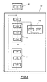
- FIG. 1 represents a system 2 for regulating the torque electromagnetic average of a motor 4 equipped with a stator and a rotor.
- this engine 4 is a three-phase synchronous motor with smooth poles with permanent magnets mounted on the surface of the rotor.
- the stator is equipped with stator windings.
- the system 2 is able to receive as input an average torque setpoint ⁇ cm and to output control signals of a conventional three-phase inverter 8.
- This inverter 8 is powered by a DC voltage source 10.
- this inverter 8 comprises three arms or "leg" in English, each formed by two switches connected in series by through a midpoint. The midpoint of each arm is connected to the stator windings of the motor 4 so as to supply voltage and current each phase of this engine.
- the system 2 comprises a control unit 20 of the inverter 8 as a function of an instantaneous torque setpoint and a calculation unit 22 of this instantaneous torque setpoint as a function of the setpoint ⁇ cm
- the control unit 20 comprises a control module 24 to response battery and a module 26 for controlling the switching of the switches of the inverter 8 by pulse width modulation.
- the module 24 receives as input the instantaneous torque setpoint in the form of an instantaneous current vector and outputs a voltage vector V .
- the instantaneous current vector is defined in an orthonormal reference rotating d, q linked to the flow of the rotor of the motor 4 and whose axis d is aligned with the rotor flux of the motor and whose axis q is deduced from the axis d by a rotation of ⁇ / 2 in the direct trigonometric direction.
- the vector of tension V is defined, in a fixed orthonormal reference ⁇ , ⁇ linked to the stator of the motor 4, by its module ⁇ V ⁇ and an angle ⁇ 0 with respect to the axis ⁇ .
- the d, q and ⁇ , ⁇ markers are conventional in this technical field and the transformation of the coordinates expressed in one coordinate system into those expressed in the other reference is done by rotation of the reference axes.
- the module 24 outputs the angle ⁇ 0 and the average of the voltage vector module V between two times of regulation.
- the angle ⁇ 0 is transmitted directly to an input of the control module 26 while the module ⁇ V ⁇ is transmitted to a module 28 for selecting the type of modulation of pulse width.
- the module 24 is able to calculate the value of the voltage vector V so that at the next instant of regulation, the instantaneous torque setpoint corresponding to the setpoint be reached.
- the module 24 implements a stack response control process also known as the English word "deadbeat control".
- the process used is described in the patent application EP-A-123 35 06. It will therefore suffice to recall that the relationship used to calculate the value of the voltage vector V according to the instruction entry is as follows: in which: and is the natural evolution of the instantaneous currents of the motor stator shorted after a control interval T from the initial state of the stator current to the previous measurement and regulation moment of the currents.
- T is the time interval between the current regulation instant and the next regulation instant
- R is the stator resistance of the motor
- L is the stator inductance of the motor
- ⁇ is the stator time constant
- the module 26 is able to control the switching of the switches of the inverter 8 as a function of the value of the angle ⁇ 0 calculated by the module 24 and the value of angles ⁇ i selected by the module 28.
- the module 26 implements a conventional synchronous pulse width modulation process with the fundamental frequency of the voltage generated by the inverter 8. An example of a control signal generated by this module 26 is shown in FIG. .
- FIG. 2 shows the evolution of the control signal of an upper switch of an arm of the inverter 8 over time.
- the value 0 of the signal indicates that the opening of the switch is controlled while the value 1 indicates that the closing of the switch is controlled.
- FIG. 2 represents the instants of regulation as a function of the phase of the fundamental voltage generated by the inverter 8.
- the interval [0,2 ⁇ ] is divided into four equal subintervals ⁇ 1 , ⁇ 2 , ⁇ 3 and ⁇ 4 .
- the switching moments of the switch are defined by angles ⁇ i .
- seven angles ⁇ i are necessary to define the commutations of the switch during the interval ⁇ 1 and the pulse width modulation represented here is thus called "seven angles".
- the switching instants in the intervals ⁇ 2 to ⁇ 4 are deduced from those defined for the interval ⁇ 1 by conventional transformations.
- the control signals of the other switches are deduced from that of FIG. 2 by shifting the signal of FIG. 2 from 2 ⁇ / p , where p is the number of phases of the motor 4.
- control signal here presents two axes of symmetry at abscissae ⁇ / 2 and 3 ⁇ / 2, and a point of symmetry P at the abscissa ⁇ .
- a type of modulation is defined once the value of the angles ⁇ i is known.
- the value of the angles ⁇ i fixes the modulus of the fundamental of the voltage generated by the inverter.
- the module 28 is able to select the value of the angles ⁇ i corresponding to the voltage modules ⁇ V ⁇ .
- the module 28 is associated with a memory 32 containing a table TP of the following form:
- this table also associates with each standardized value of the module ⁇ V ⁇ , the value of two parameters ⁇ (0) and ⁇ (0). The calculation of the value of these parameters as well as their interest will appear on reading the rest of the description.
- the module 28 is therefore also able to select and output the value of the parameters ⁇ (0) and ⁇ (0) corresponding to the value of the module ⁇ V ⁇ .
- the selection module 28 is able to calculate by linear interpolation the corresponding values of the parameters ⁇ (0) and ⁇ (0) and angles ⁇ i .
- the relation (2) is obtained by solving the system of equations (1) to which is added an additional equation to express the constraint according to which the phase of the voltage vector must be equal to k ⁇ / p , where k is an integer between [1, ..., 6] and p is the number of phases of the motor 4.
- this additional equation is for example the following: where V ⁇ , V ⁇ are the components of the voltage vector in the frame ⁇ , ⁇ .
- the calculation unit 22 converts the average torque setpoint ⁇ cm into an instantaneous torque setpoint expressed as the instantaneous current vector setpoint.
- it comprises a module 40 for calculating a fundamental current setpoint a module 42 for correcting this fundamental current setpoint and a module 44 for setting the setpoint taking into account the operating limits of the inverter 8.
- N p and ⁇ a are known parameters functions of the characteristics of the engine 4.
- the harmonic current vector is the corresponding one only harmonics of the current generated by the inverter 8 without taking into account the fundamental.
- the instantaneous maximum intensity Î M is constant and known from the electrical characteristics of the inverter 8. The calculation of the value of the components ⁇ I d , ⁇ J q and ⁇ J d is defined below.
- the system 2 also comprises a unit 50 for determining the harmonic voltage and current vectors along the axes d and q of the d, q mark.
- the unit 50 comprises a first module 52 for determining the harmonic current vector and a second module 54 for determining the harmonic voltage vector. More precisely, the module 52 is able to deliver the value of the components ⁇ I q and ⁇ I d to the modules 42 and 44 and the module 54 is able to deliver the value of the components ⁇ J q and ⁇ J d to the module 44.
- the module 54 establishes the components ⁇ J q and ⁇ J d using the following formulas:
- the modules 52 and 54 are also connected to the outputs of the module 24 and the module 28, so as to obtain the value of the angle ⁇ 0 and the value of the parameters ⁇ (0) and ⁇ (0).
- the system 2 comprises a sensor 56 of the angular position ⁇ 0 of the rotor of the motor 4, a sensor 58 of the angular velocity ⁇ of the rotor of the motor 4, a sensor 60 of the instantaneous DC voltage V and M delivered by the source. 10 to the inverter 8, and a sensor 62 of the instantaneous current in the stator windings.
- the sensor 62 is formed by a plurality of elementary current sensors each adapted to measure the current in the stator windings of a phase of the motor 4, so as to measure the instantaneous current vector. This sensor 62 is also able to transform the instantaneous current vector measured by the generalized Concordia transformation to a polyphase system, so as to output directly the two components of the instantaneous current vector Î d (0) and Î q ( 0).
- sensors are connected to the different modules that require a measurement of these values.
- the sensor 56 delivers the value of the angle ⁇ 0 to the modules 52 and 54.
- the connections between the sensors 56 to 62 and the various modules of the system 2 have not all been shown to simplify the illustration.
- the system 2 is typically realized using calculators conventional programmable electronics.
- system 2 is associated with a memory 61 containing instructions for executing the method of Figure 3, when these are executed by the system 2.
- the process of Figure 3 breaks down into two main phases, an initialization phase 80 of the different constant parameters used by the modules of the system 2, and a phase 82 of the regulation of the torque of the engine 4.
- the value of the parameters N p , ⁇ a , Î M , R, L and Z is determined from the electrical and mechanical characteristics of the motor and the inverter 8. Once determined, the value of these parameters is, for example, stored in the memory 61.
- the amplitude of the harmonics varies according to the type of modulation, that is to say as a function of the value of the angles ⁇ i and the instantaneous value of the DC voltage.
- the value of these parameters ⁇ (0) and ⁇ (0) is calculated by simulation of a numerical model of the motor 4 and of the inverter 8. More specifically, during an operation 84 , the power supply of the motor 4 by means of the pulse width modulation defined by the angles ⁇ i1 recorded in the memory 32, is simulated. The three-phase voltage generated by the model is then analyzed and the value of the amplitude, for example, of the first 2000 voltage harmonics higher than two is measured. Using these 2000 values and relations (14) and (15) above, the value of the parameters ⁇ (0) and ⁇ (0) is calculated for the pulse width modulation defined by the angles ⁇ i1 .
- a normalized value of the parameters ⁇ (0) and ⁇ (0) thus calculated is recorded in the table TP of the memory 32 on the line corresponding to the angles ⁇ i1 .
- the normalized value of ⁇ (0) and ⁇ (0) is obtained by dividing them by the value V and M.
- operation 84 is reiterated for each type of modulation defined in table TP of memory 32.
- the value of the parameters ⁇ (0) and ⁇ (0) defined for each type of modulation is stored in memory 32.
- phase 82 of regulation can to start.
- the system 2 receives, during an operation 90, the value of the instruction ⁇ cm .
- This instruction ⁇ cm is, for example, delivered by an operator or a servo device not shown.
- the value of this setpoint ⁇ cm generally varies slowly with respect to the frequency with which a new instantaneous current setpoint is delivered to module 24.
- the unit 22 calculates, during a step 92, a new instantaneous current setpoint This new directive is applied to the input of the control unit 20.
- the unit 20 controls, in a step 94, the inverter 8 as a function of this instantaneous current setpoint.
- the instantaneous current setpoint remains constant between two instants of regulation.
- the module 24 establishes, during an operation 96, at the current regulation time, the value of the angle ⁇ 0 and the module ⁇ V ⁇ which allows to obtain, from the next instant of regulation, the instantaneous torque corresponding to the instantaneous current setpoint
- the angle ⁇ 0 of the voltage vector V established by the module 24 is transmitted directly to the module 26, while the module ⁇ V ⁇ of this same vector is transmitted to the selection module 28.
- the module 28 selects, during an operation 98, the value of the angles ⁇ i and the value of the parameters ⁇ (0) and ⁇ (0) corresponding to the value of the module ⁇ V ⁇ .
- the recorded value of the parameters ⁇ (0) and ⁇ (0) is multiplied by the value V and M measured at this instant.
- the selected value of the angles ⁇ i is transmitted to the module 26 while the non-normalized value of the parameters ⁇ (0) and ⁇ (0) is transmitted respectively to the modules 52 and 54.
- the module 26 controls, during an operation 100, the switching of the switches of the inverter 8 by implementing a modulation process of width synchronous pulse.
- the inverter 8 Under the control of the module 26, the inverter 8 generates a voltage and a current corresponding to the module ⁇ V ⁇ and at the angle ⁇ 0 .
- the instantaneous torque of the motor reaches exactly at the instant of regulation the instantaneous torque setpoint corresponding to the input setpoint This is shown in the graph of FIG. 4.
- the horizontal thin line represents the instantaneous torque setpoint corresponding to the setpoint
- the line in bold represents the evolution over time of the instantaneous couple ⁇ s .
- the instantaneous torque is equal to the instantaneous torque setpoint.
- the average of the instantaneous torque represented by a horizontal dashed line between two control instants is, for example, on this graph, less than the value of the instantaneous torque setpoint corresponding to the setpoint.
- step 110 of determining the value of the harmonics of current and of voltage and step 92 includes specific computing operations that go now be described.
- the values determined during this operation 112 are then transmitted to the modules 42 and 44 of the computing unit 22.
- the module 54 determines, during an operation 114, the value of the components ⁇ J q and ⁇ J d .
- the values of ⁇ J q and ⁇ J d are transmitted to the module 44.
- the module 44 establishes, during an operation 124, the value of the component Î d making it possible to respect these limits.
- the fundamental current setpoint and the instantaneous current setpoint increases, which after operations 122, 124 and 96, leads to an increase of the module ⁇ V ⁇ .
- This module increase ⁇ V ⁇ leads, for example, the module 28 to select a new type of pulse width modulation corresponding to new values for the angles ⁇ i .
- the selection of a new type of pulse width modulation also leads to generating different values for the parameters ⁇ (0) and ⁇ (0).
- the modules 52 and 54 determine, during the next execution of the operation 120, the new values of the components ⁇ I q , ⁇ I d , ⁇ J q and ⁇ J d to correct the instantaneous current setpoint for example, by increasing it, so that the average between two moments of regulation of the instantaneous torque is equal to the setpoint ⁇ cm .
- the method of FIG. 3 makes it possible to regulate the average torque of the engine by implementing a stack response control process. he therefore presents a great dynamic. Moreover, here the order process at answer stack is combined with a pulse width modulation process synchronous, so that some specific harmonic ranks are eliminated.
- the operations 122, 124, 96 and 98 are repeated several times before executing the operation 100. Repeating the operations 122, 124 several times , 96 and 98 provide a value for the current setpoint more precise. Thus, if the number of iterations is sufficiently large, the instruction is sufficiently precise to allow to reach after a single moment of regulation any new value of the average torque set ⁇ cm , itself in rapid variation.
Abstract
Description
L'invention concerne un procédé et un système de régulation du couple électromagnétique moyen d'une machine électrique tournante polyphasée équipée de bobinages statoriques et/ou rotoriques. L'invention concerne également des supports d'enregistrement et une structure de données pour la mise en oeuvre de ce procédé.The invention relates to a method and a system for regulating the torque electromagnetic response of a polyphase rotating electrical machine equipped with stator and / or rotor coils. The invention relates to also record carriers and a data structure for the implementation of this method.
Plus précisément, l'invention concerne un procédé de régulation d'une machine dans laquelle les bobinages statoriques et/ou rotoriques sont alimentés par une tension et un courant polyphasés générés par un onduleur, l'onduleur étant formé d'interrupteurs dont la commutation est commandable, ce procédé comportant :
- une étape de commande de la commutation des interrupteurs en fonction d'une consigne de couple instantané, en mettant en oeuvre à cet effet un processus de commande à réponse pile de manière à ce que la consigne de couple instantané soit atteinte dès le prochain instant de régulation, et
- à chaque instant de régulation, une étape de calcul, à partir d'une consigne de couple moyen, de la consigne de couple instantané à appliquer pour que la moyenne du couple électromagnétique instantané de la machine converge vers ladite consigne de couple moyen.
- a step of controlling the switching of the switches as a function of an instantaneous torque setpoint, by implementing for this purpose a stack response control process so that the instantaneous torque setpoint is reached as soon as the next instant of regulation, and
- at each regulation instant, a step of calculating, from an average torque setpoint, the instantaneous torque setpoint to be applied so that the average of the instantaneous electromagnetic torque of the machine converges towards said average torque setpoint.
Dans la suite de la description, on utilisera le terme "moteur" pour désigner une machine électrique tournante polyphasée et le terme "couple" pour désigner le couple électromagnétique d'une telle machine.In the rest of the description, the term "motor" will be used for designate a polyphase rotating electrical machine and the term "torque" for designate the electromagnetic torque of such a machine.
Les procédés ci-dessus présentent une très grande dynamique de régulation puisque la consigne de couple instantané peut être modifiée à chaque instant de régulation et elle est atteinte dès le prochain instant de régulation.The processes above have a very great dynamic of regulation since the instantaneous torque setpoint can be changed at each moment of regulation and it is reached at the next moment of regulation.
Ainsi, de tels procédés de commande sont particulièrement utiles pour des applications où la consigne de couple change brusquement. Par exemple, ces procédés sont utilisés pour commander des moteurs d'entraínement d'un laminoir.Thus, such control methods are particularly useful for applications where the torque setpoint changes abruptly. For example, these methods are used to control drive motors of a rolling mill.
Toutefois, lorsque la consigne de couple instantané est obtenue par simple égalisation en assimilant par exemple la consigne de couple moyen à la consigne de couple instantané, il existe un écart entre la valeur de la consigne de couple moyen et la moyenne du couple instantané entre deux instants de régulation successifs. Dès lors, la consigne de couple moyen n'est soit jamais parfaitement atteinte, soit atteinte en faisant la moyenne du couple instantané sur un grand nombre d'instants de régulation de sorte que le procédé ne présente plus une grande dynamique de régulation.However, when the instantaneous torque setpoint is obtained by simple equalization by assimilating for example the average torque setpoint to the instantaneous torque setpoint, there is a difference between the setpoint value of average torque and the average instantaneous torque between two instants of successive regulation. Therefore, the average torque instruction is never perfectly achieved, be achieved by averaging the instantaneous torque on a large number of times of regulation so that the process does not present more a great dynamics of regulation.
L'invention vise à remédier à cet inconvénient en proposant un procédé de régulation du couple électromagnétique moyen présentant une grande dynamique de régulation.The aim of the invention is to remedy this drawback by proposing a method regulating the average electromagnetic torque having a large dynamic regulation.
L'invention a donc pour objet un procédé de régulation du couple électromagnétique moyen tel que décrit ci-dessus, caractérisé en ce qu'il comporte une étape de détermination de la valeur des harmoniques du courant et/ou de la tension générés par l'onduleur, et en ce que, lors de l'étape de calcul, la consigne de couple instantané est également établie en fonction de cette valeur des harmoniques de manière à produire une consigne de couple instantané propre à limiter l'écart entre la moyenne du couple électromagnétique instantané entre deux instants de régulation successifs, et ladite consigne de couple moyen.The subject of the invention is therefore a method for regulating the torque electromagnetic means as described above, characterized in that includes a step of determining the value of the harmonics of the current and / or the voltage generated by the inverter, and in that, during the calculation step, the instantaneous torque setpoint is also established according to this harmonic value to produce a torque setpoint instant clean to limit the gap between the average electromagnetic torque snapshot between two successive regulation instants, and said setpoint of average couple.
Il a été constaté que l'écart entre la consigne de couple moyen et la moyenne du couple instantané entre deux instants de régulation successifs est dû au fait que l'onduleur ne peut pas générer des tensions ou des courants parfaitement sinusoïdaux à partir d'une tension continue. En réalité, la tension et le courant générés se décomposent en une composante sinusoïdale à une fréquence fondamentale et en des composantes sinusoïdales de fréquences plus élevées correspondant aux harmoniques de rang supérieur ou égal à deux. Ici, la composante sinusoïdale de fréquence fondamentale est simplement appelée le fondamental tandis que les composantes sinusoïdales de fréquences plus élevées sont appelées harmoniques.It was found that the difference between the average torque setpoint and the average instantaneous torque between two successive regulation instants is due to the fact that the inverter can not generate voltages or currents perfectly sinusoidal from a DC voltage. In reality, the tension and the generated current break down into a sinusoidal component at a fundamental frequency and into sinusoidal components of higher frequencies corresponding to harmonics of rank greater than or equal to two. Here, the sinusoidal component of fundamental frequency is simply called the fundamental while the sinusoidal components of higher frequencies high are called harmonics.
Le fondamental crée un couple constant Γm sur une période du fondamental. Les harmoniques engendrent un couple pulsatoire parasite de fréquence plus élevée. Le couple instantané Γs du moteur est le résultat de la superposition du couple Γm et du couple pulsatoire. Le couple pulsatoire et le couple Γm sont indépendants l'un de l'autre. Dès lors, les procédés connus qui calculent une consigne de couple instantané uniquement en fonction de la consigne de couple moyen ne tienne pas compte du couple pulsatoire. Ainsi, même si, par exemple, le couple instantané à chaque instant de régulation est rigoureusement identique à la consigne de couple moyen, la moyenne du couple instantané Γs entre deux instants de régulation successifs n'est pas égale à cette consigne de couple moyen puisque le couple instantané varie entre ces deux instants à cause du couple pulsatoire. Le couple pulsatoire est donc responsable de l'écart entre la consigne de couple moyen et la moyenne du couple instantané. Cet écart est d'autant plus important que l'amplitude du couple pulsatoire est importante. Donc, puisque le couple pulsatoire est créé par les harmoniques de tension et/ou de courant, la valeur de cet écart est fonction de la valeur des harmoniques.The fundamental creates a constant couple Γ m over a fundamental period. Harmonics generate a parasitic pulsating torque of higher frequency. The instantaneous torque Γ s of the motor is the result of the superposition of the torque Γ m and the pulsating torque. The pulsating torque and the torque Γ m are independent of each other. Therefore, the known methods that calculate an instantaneous torque setpoint only as a function of the average torque setpoint do not take into account the pulsating torque. Thus, even if, for example, instant each time torque control is exactly the same average torque setpoint, the average of the instantaneous torque Γ s between two successive regulation times is not equal to the average torque setpoint since the instantaneous torque varies between these two moments because of the pulsating torque. The pulsating torque is therefore responsible for the difference between the average torque setpoint and the average instantaneous torque. This difference is all the more important as the amplitude of the pulsating torque is important. Therefore, since the pulsating torque is created by the voltage and / or current harmonics, the value of this difference is a function of the harmonic value.
Le procédé ci-dessus corrige le défaut des procédés connus en prenant en compte pour le calcul de la consigne de couple instantané, non seulement la consigne de couple moyen, mais également la valeur des harmoniques de courant et/ou de tension.The above process corrects the defect of the known processes in taking into account for the calculation of the instantaneous torque setpoint, no only the average torque setpoint, but also the value of the harmonic current and / or voltage.
Suivant d'autres caractéristiques du procédé conforme à l'invention, celui-ci se caractérise en ce que :
- le processus de commande à réponse pile établit une consigne de commande des interrupteurs par modulation de largeur d'impulsions, et en ce que l'étape de commande comporte également, entre chaque instant de régulation, une opération de commande de la commutation des interrupteurs en mettant en oeuvre un processus de modulation de largeur d'impulsions configuré en fonction de ladite consigne de commande établie par le processus de commande à réponse pile ;
- le processus de modulation de largeur d'impulsions est un processus de modulation de largeur d'impulsions synchrone avec la fréquence du fondamental de la tension générée par l'onduleur, et en ce que les instants de régulation sont espacés les uns des autres par un intervalle temporel égal à T'/2p , où p est le nombre de phases de la machine et T'est la période du fondamental de la tension générée par l'onduleur ;
- le processus de commande à réponse pile est adapté pour qu'aux instants de régulation la phase du fondamental de la tension générée par l'onduleur soit égale à kπ / p, k étant un nombre entier ;
- la valeur des harmoniques est établie, lors de l'étape de détermination, à partir de la valeur de la consigne de commande établie par le processus de commande à réponse pile à l'instant de régulation précédent ;
- le processus de modulation de largeur d'impulsions utilise successivement dans le temps plusieurs modulations différentes de largeur d'impulsions ; la valeur des harmoniques est établie à partir d'au moins un paramètre de calcul, les différentes valeurs du ou de chaque paramètre étant calculées à l'avance et pré-enregistrées pour chaque modulation différente de largeur d'impulsions susceptible d'être utilisée ; et la valeur du ou de chaque paramètre à utiliser lors de l'étape de détermination, est sélectionnée en fonction de la valeur de la consigne de commande établie par le processus de commande à réponse pile à l'instant de régulation précédent ;
- un paramètre de calcul est défini par la relation suivante :
où :

- Vn est l'amplitude de l'harmonique de tension de rang n ;
- n est un nombre entier correspondant au rang de l'harmonique ;
- la consigne de commande est un vecteur de tension défini, dans un
repère orthonormé α,β fixe par rapport aux bobinages statoriques, par son
module et un angle et en ce que la valeur des harmoniques de courant est établie
à partir de la relation suivante :
- L est l'inductance statorique de la machine électrique tournante,
- ω est la vitesse angulaire du rotor de la machine électrique tournante,
- β0 est l'angle du vecteur de tension établi (en 96) à l'instant de régulation précédent par le processus de commande à réponse pile,
- ΔIq est la valeur des harmoniques de courant le long de l'axe q dans un repère tournant d, q lié au flux rotorique, le flux rotorique étant aligné sur l'axe d, et
- ρ0 est l'angle du repère d,q par rapport au repère fixe α,β lié aux bobines statoriques.
- un paramètre de calcul est défini par la relation suivante :
où Vn est l'amplitude de l'harmonique de tension de rang n ;

- l'onduleur est alimenté à partir d'au moins une tension continue d'alimentation limitée en amplitude, et en ce que, lors de l'étape de calcul, la consigne de couple instantané est également établie en fonction de la valeur instantanée de la tension continue disponible à l'instant de régulation, de manière à ce que la consigne de couple instantané corresponde à une tension continue disponible.
- la consigne de couple instantané est établie sous la forme d'une
consigne de courant instantané à l'aide des relations suivantes :

- V andM est la valeur instantanée de la tension maximale continue disponible pour alimenter l'onduleur,
- ÎM est la valeur instantanée du courant maximal pouvant être généré par l'onduleur 8,
- Îq et Îd sont les composantes de la consigne du vecteur de courant instantané le long respectivement des axes q et d du repère d, q
- Z est défini par la relation suivante :
- Îdc et Îqc sont définis par les relations suivantes :
 où:
où:
- ΔId et ΔIq sont les composantes du vecteur de courant
harmonique généré par l'onduleur, le long respectivement des axes d et q du
repère d,q, et ΔJq et ΔJd sont des composantes proportionnelles au vecteur
de tension harmonique généré par l'onduleur, respectivement le long des axes q
et d du repère d, q, les composantes ΔId , ΔJq et ΔJd étant définies par les
relations suivantes :


- the battery response control process establishes a control setpoint of the switches by pulse width modulation, and in that the control step also comprises, between each regulation instant, a control operation of the switching of the switches. implementing a pulse width modulation process configured according to said control setpoint established by the battery response control process;
- the pulse width modulation process is a pulse width modulation process synchronous with the fundamental frequency of the voltage generated by the inverter, and in that the control times are spaced from each other by a time interval equal to T '/ 2p, where p is the number of phases of the machine and T is the fundamental period of the voltage generated by the inverter;
- the battery response control process is adapted so that at the control instants the phase of the fundamental of the voltage generated by the inverter is equal to kπ / p , where k is an integer;
- the value of the harmonics is established, during the determination step, from the value of the command setpoint established by the battery response control process at the previous regulation time;
- the pulse width modulation process successively uses in time a plurality of different pulse width modulations; the value of the harmonics is established from at least one calculation parameter, the different values of the or each parameter being calculated in advance and pre-recorded for each different modulation of pulse width that may be used; and the value of the or each parameter to be used in the determining step is selected according to the value of the command setpoint set by the battery response control process at the previous control instant;
- a calculation parameter is defined by the following relation: or :
- V n is the amplitude of the voltage harmonic of rank n;
- n is an integer corresponding to the rank of the harmonic;
- the control setpoint is a voltage vector defined, in an orthonormal coordinate system α, β fixed with respect to the stator windings, by its modulus and an angle, and in that the value of the current harmonics is established from the following relation:
- L is the stator inductance of the rotating electrical machine,
- ω is the angular velocity of the rotor of the rotating electrical machine,
- β 0 is the angle of the established voltage vector (at 96) at the previous control instant by the stack response control process,
- ΔI q is the value of the current harmonics along the axis q in a rotating reference d, q linked to the rotor flux, the rotor flux being aligned on the axis d, and
- ρ 0 is the angle of the reference d, q with respect to the fixed reference α, β related to the stator coils.
- a calculation parameter is defined by the following relation: where Vn is the amplitude of the voltage harmonic of rank n;
- the inverter is supplied with at least one supply voltage limited in amplitude, and that, during the calculation step, the instantaneous torque setpoint is also established as a function of the instantaneous value of the DC voltage available at the instant of regulation, so that the instantaneous torque setpoint corresponds to an available DC voltage.
- the instantaneous torque setpoint is established in the form of an instantaneous current setpoint using the following relations:
- V and M is the instantaneous value of the maximum continuous voltage available to supply the inverter,
- Î M is the instantaneous value of the maximum current that can be generated by the inverter 8,
- Î q and Î d are the components of the instantaneous current vector set along respectively the q and d axes of the d, q mark
- Z is defined by the following relation:
- Î dc and Î qc are defined by the following relationships: or:
- ΔI d and ΔI q are the components of the harmonic current vector generated by the inverter, along respectively the d and q axes of the d, q, and ΔJ q and ΔJ d are proportional components to the harmonic voltage vector generated by the inverter, respectively along the axes q and d of the reference d, q, the components ΔI d , ΔJ q and ΔJ d being defined by the following relations:
L'invention a également pour objet un support d'enregistrement d'informations, caractérisé en ce qu'il comporte des instructions pour l'exécution d'un procédé de régulation conforme à l'invention, lorsque ces instructions sont exécutées par un calculateur électronique.The subject of the invention is also a recording medium information, characterized in that it includes instructions for execution of a control method according to the invention, when these instructions are executed by an electronic calculator.
L'invention a également pour objet une structure de données, caractérisée en ce que cette structure de données associe à chaque valeur particulière d'une consigne de commande établie par le processus de commande à réponse pile, plusieurs angles et la valeur d'au moins un paramètre de régulation, l'ensemble des angles associés avec une même valeur de ladite consigne de commande, définissant une modulation particulière de largeur d'impulsions synchrone avec la fréquence du fondamental de la tension générée par l'onduleur, et la valeur dudit au moins un paramètre de régulation étant fonction de la valeur des harmoniques de courant et/ou de tension générés par l'onduleur commandé à l'aide de la modulation de largeur d'impulsions définie par les angles associés à la même valeur de la consigne de commande.The subject of the invention is also a data structure, characterized in that this data structure associates with each value particular of a command set established by the order process response, multiple angles and the value of at least one parameter of regulation, the set of angles associated with the same value of said command setpoint, defining a particular modulation of width of pulses synchronous with the fundamental frequency of the voltage generated by the inverter, and the value of said at least one regulating parameter being function of the value of the current and / or voltage harmonics generated by the inverter controlled using the pulse width modulation defined by the angles associated with the same value of the command setpoint.
L'invention a également pour objet un système de régulation du couple électromagnétique moyen d'une machine électrique tournante polyphasée équipée de bobinages statoriques et/ou rotoriques alimentés par une tension et un courant polyphasés générés par un onduleur, l'onduleur étant formé d'interrupteurs dont la commutation est commandable, ce système comportant :
- une unité de commande de la commutation des interrupteurs en fonction d'une consigne de couple instantané, cette unité de commande étant apte à mettre en oeuvre à cet effet un processus de commande à réponse pile de manière à ce que la consigne de couple instantané soit atteinte dès le prochain instant de régulation ;
- une unité de calcul, à partir d'une consigne de couple moyen, de la consigne de couple instantané à appliquer pour que la moyenne du couple électromagnétique instantané de la machine converge vers ladite consigne de couple moyen ;
- a control unit for switching the switches according to an instantaneous torque setpoint, this control unit being able to implement for this purpose a stack response control process so that the instantaneous torque setpoint is reached at the next moment of regulation;
- a calculation unit, from an average torque setpoint, of the instantaneous torque setpoint to be applied so that the average of the instantaneous electromagnetic torque of the machine converges towards said average torque setpoint;
L'invention sera mieux comprise à la lecture de la description qui va suivre, donnée uniquement à titre d'exemple et faite en se référant aux dessins sur lesquels :
- la figure 1 est une illustration schématique d'un système de régulation conforme à l'invention,
- la figure 2 est un graphique représentant l'évolution au cours du temps d'un signal de commande généré par le système de la figure 1,
- la figure 3 est un organigramme d'un procédé de régulation conforme à l'invention, et
- la figure 4 est un graphique représentant l'évolution du couple instantané au cours du temps dans le cas du procédé de régulation de la figure 3.
- FIG. 1 is a schematic illustration of a control system according to the invention,
- FIG. 2 is a graph showing the evolution over time of a control signal generated by the system of FIG. 1,
- FIG. 3 is a flowchart of a regulation method according to the invention, and
- FIG. 4 is a graph showing the evolution of instantaneous torque over time in the case of the control method of FIG. 3.
La figure 1 représente un système 2 de régulation du couple électromagnétique moyen d'un moteur 4 équipé d'un stator et d'un rotor.FIG. 1 represents a system 2 for regulating the torque electromagnetic average of a motor 4 equipped with a stator and a rotor.
La suite de la description sera faite dans le cas particulier où ce moteur 4 est un moteur triphasé synchrone à pôles lisses à aimants permanents montés en surface du rotor. Le stator est équipé de bobinages statoriques.The rest of the description will be made in the particular case where this engine 4 is a three-phase synchronous motor with smooth poles with permanent magnets mounted on the surface of the rotor. The stator is equipped with stator windings.
En particulier, les relations mathématiques données dans la suite de cette description sont celles établies à partir des équations d'état d'un tel moteur. In particular, the mathematical relationships given in the following this description are those established from the equations of state of such an engine.
Le système 2 est apte à recevoir en entrée une consigne de couple moyen Γcm et à délivrer en sortie des signaux de commande d'un onduleur triphasé conventionnel 8. Cet onduleur 8 est alimenté par une source 10 de tension continue.The system 2 is able to receive as input an average torque setpoint Γ cm and to output control signals of a conventional three-phase inverter 8. This inverter 8 is powered by a DC voltage source 10.
De façon classique, cet onduleur 8 comporte trois bras ou "leg" en anglais, formés chacun de deux interrupteurs raccordés en série par l'intermédiaire d'un point milieu. Le point milieu de chaque bras est raccordé aux bobinages statoriques du moteur 4 de manière à alimenter en tension et en courant chaque phase de ce moteur.In a conventional manner, this inverter 8 comprises three arms or "leg" in English, each formed by two switches connected in series by through a midpoint. The midpoint of each arm is connected to the stator windings of the motor 4 so as to supply voltage and current each phase of this engine.
Le système 2 comporte une unité de commande 20 de l'onduleur 8 en fonction d'une consigne de couple instantané et une unité de calcul 22 de cette consigne de couple instantané en fonction de la consigne Γcm The system 2 comprises a control unit 20 of the inverter 8 as a function of an instantaneous torque setpoint and a calculation unit 22 of this instantaneous torque setpoint as a function of the setpoint Γ cm
L'unité de commande 20 comporte un module 24 de commande à réponse pile et un module 26 de commande de la commutation des interrupteurs de l'onduleur 8 par modulation de largeur d'impulsions.The control unit 20 comprises a control module 24 to response battery and a module 26 for controlling the switching of the switches of the inverter 8 by pulse width modulation.
Le module 24 reçoit en entrée la consigne de couple instantané sous la
forme d'un vecteur de courant instantané
![]()
![]()
Le vecteur de courant instantané
![]()
![]()
Plus précisément, le module 24 délivre en sortie l'angle β0 et la
moyenne du module du vecteur de tension
L'angle β0 est transmis directement à une entrée du module 26 de
commande tandis que le module ∥
Le module 24 est apte à calculer la valeur du vecteur de tension ![]()
![]()


![]()
![]()
T est l'intervalle de temps entre l'instant de régulation courant et le
prochain instant de régulation, R est la résistance statorique du moteur, L est
l'inductance statorique du moteur et τ est la constante de temps statorique

Le module 26 est propre à commander la commutation des interrupteurs de l'onduleur 8 en fonction de la valeur de l'angle β0 calculé par le module 24 et de la valeur d'angles αi sélectionnés par le module 28. A cet effet, le module 26 met en oeuvre un processus conventionnel de modulation de largeur d'impulsions synchrone avec la fréquence du fondamental de la tension générée par l'onduleur 8. Un exemple de signal de commande généré par ce module 26 est représenté sur la figure 2.The module 26 is able to control the switching of the switches of the inverter 8 as a function of the value of the angle β 0 calculated by the module 24 and the value of angles α i selected by the module 28. For this purpose , the module 26 implements a conventional synchronous pulse width modulation process with the fundamental frequency of the voltage generated by the inverter 8. An example of a control signal generated by this module 26 is shown in FIG. .
La figure 2 représente l'évolution du signal de commande d'un interrupteur supérieur d'un bras de l'onduleur 8 au cours du temps. Ici, par exemple, la valeur 0 du signal indique que l'ouverture de l'interrupteur est commandée tandis que la valeur 1 indique que la fermeture de l'interrupteur est commandée. La figure 2 représente les instants de régulation en fonction de la phase du fondamental de tension généré par l'onduleur 8. L'intervalle [0,2π] est divisé en quatre sous-intervalles égaux π1, π2, π3 et π4. Dans l'intervalle π1, les instants de commutation de l'interrupteur sont définis par des angles αi. Ici, sept angles αi sont nécessaires pour définir les commutations de l'interrupteur pendant l'intervalle π1 et la modulation de largeur d'impulsions représentée ici est donc dite "sept angles". Les instants de commutation dans les intervalles π2 à π4 se déduisent de ceux définis pour l'intervalle π1 par des transformations classiques. Les signaux de commande des autres interrupteurs se déduisent de celui de la figure 2 en décalant de 2π / p le signal de la figure 2, où p est le nombre de phases du moteur 4.Figure 2 shows the evolution of the control signal of an upper switch of an arm of the inverter 8 over time. Here, for example, the value 0 of the signal indicates that the opening of the switch is controlled while the value 1 indicates that the closing of the switch is controlled. FIG. 2 represents the instants of regulation as a function of the phase of the fundamental voltage generated by the inverter 8. The interval [0,2π] is divided into four equal subintervals π 1 , π 2 , π 3 and π 4 . In the interval π 1 , the switching moments of the switch are defined by angles α i . Here, seven angles α i are necessary to define the commutations of the switch during the interval π 1 and the pulse width modulation represented here is thus called "seven angles". The switching instants in the intervals π 2 to π 4 are deduced from those defined for the interval π 1 by conventional transformations. The control signals of the other switches are deduced from that of FIG. 2 by shifting the signal of FIG. 2 from 2π / p , where p is the number of phases of the motor 4.
De manière à éliminer les harmoniques de rang pair et les harmoniques de rang multiple de trois, le signal de commande présente ici deux axes de symétrie aux abscisses π / 2 et 3π / 2, et un point de symétrie P à l'abscisse π.In order to eliminate even-order harmonics and harmonics of multiple rank of three, the control signal here presents two axes of symmetry at abscissae π / 2 and 3π / 2, and a point of symmetry P at the abscissa π.
Ainsi, un type de modulation est défini une fois que la valeur des angles αi est connue. La valeur des angles αi fixe le module du fondamental de la tension générée par l'onduleur.Thus, a type of modulation is defined once the value of the angles α i is known. The value of the angles α i fixes the modulus of the fundamental of the voltage generated by the inverter.
Le module 28 est apte à sélectionner la valeur des angles αi
correspondants aux modules de tension ∥
Ce tableau est propre à associer à chaque valeur normalisée ∥
- V andM est la valeur instantanée de la tension aux bornes de la source 10.
- V and M is the instantaneous value of the voltage across the source 10.
De plus, ce tableau associe également à chaque valeur normalisée du
module ∥
Si la valeur normalisée ∥
L'unité de commande 20 comporte également un module 30 de
détermination des instants de régulation. Ce module 30 est apte à déterminer
l'intervalle T entre deux instants de régulation successifs pour que celui-ci soit
égale à T / 2p, où T' est la période du fondamental de la tension générée par
l'onduleur 8 et p le nombre de phases du moteur 4. En effet, il a été constaté que
ce choix de la valeur de l'intervalle T élimine certains rangs d'harmoniques de
tension générés par l'onduleur 8. De plus, ici, pour simplifier certaines des
relations décrites ci-dessous, ces instants de régulation sont déterminés pour
correspondre à des instants où la phase du vecteur de tension 
- les angles ϕ D et ϕ 0 sont définis par les relations suivantes :
- I D / d(T), I D / q(T), I D / d(0) et I D / q(0) sont définis par les relations
suivantes :
Où:

- Φ a est le flux rotorique des aimants,
- L est l'inductance statorique du moteur,
- X est défini par la relation X = L.ω, où ω est la vitesse angulaire du rotor,
- Z est défini par la relation suivante Z2 = R2 + L 2 ·
ω 2 - Îd (0) et Îq (0) sont les composantes dans le repère d,q du vecteur de courant instantané mesuré à l'instant de régulation courant,
- Îd et Îq est la consigne de courant reçue à l'entrée du module 24.
- the angles φ D and φ 0 are defined by the following relations:
- I D / d ( T ), I D / q ( T ), I D / d (0) and I D / q (0) are defined by the following relationships: Or:
- Φ a is the rotor flux of the magnets,
- L is the stator inductance of the motor,
- X is defined by the relation X = L.ω, where ω is the angular velocity of the rotor,
- Z is defined by the following relationship Z 2 = R 2 + L 2 ·
ω 2 - Î d (0) and Î q (0) are the components in the d, q coordinate of the instantaneous current vector measured at the current regulation instant,
- Î d and Î q is the current setpoint received at the input of the module 24.
La relation (2) est obtenue en résolvant le système d'équations (1)
auquel est adjointe une équation supplémentaire pour exprimer la contrainte
selon laquelle la phase du vecteur de tension doit être égale à kπ / p, où k est un
entier compris entre [1,...,6] et p est le nombre de phases du moteur 4. En
triphasé, cette équation supplémentaire est par exemple la suivante :
![]()
![]()
Plus de détails sur la détermination de l'intervalle de temps T pourront être trouvés dans la demande de brevet française déposée en France le même jour par la demanderesse sous le titre de "Procédé de régulation du couple électromagnétique instantané d'une machine électrique tournante polyphasée".More details on the determination of the time interval T will be be found in the French patent application filed in France the same day by the plaintiff under the title "Method of regulating the couple instantaneous electromagnetic noise of a polyphase rotating electrical machine ".
L'unité de calcul 22 convertit la consigne de couple moyen Γcm en une
consigne de couple instantané exprimée sous la forme de la consigne de vecteur
de courant instantané
![]()
![]()
![]()
![]()
![]()
![]()
Le module 40 établit la consigne de courant fondamental ![]()

- Np est le nombre de paires de pôles du moteur,
- Φ a est le flux rotorique des aimants.
- Np is the number of motor pairs of poles,
- Φ a is the rotor flux of the magnets.
Ces deux paramètres Np et Φ a sont des paramètres connus fonctions des caractéristiques du moteur 4.These two parameters N p and Φ a are known parameters functions of the characteristics of the engine 4.
Le module 42 est propre à corriger la consigne ![]()
- Îq est la composante le long de l'axe q, dans le repère d, q, de la
consigne
et

- ΔIq est la composante du vecteur de courant harmonique le long de l'axe q du repère d, q.
- Î q is the component along the axis q, in the d, q mark of the setpoint and
- ΔI q is the component of the harmonic current vector along the q axis of the d, q mark.
Le vecteur de courant harmonique est celui correspondant uniquement aux harmoniques du courant généré par l'onduleur 8 sans prendre en compte le fondamental.The harmonic current vector is the corresponding one only harmonics of the current generated by the inverter 8 without taking into account the fundamental.
Le module 44 est apte à établir la consigne
![]()

- V andM est la valeur instantanée de la tension maximale continue disponible aux bornes de la source 10,
- ÎM est la valeur instantanée du courant maximal pouvant être généré par l'onduleur 8,
- Îd est la composante du vecteur de courant instantané le long de l'axe d du repère d, q
Îdc et Îqc sont définis par les relations suivantes :


- ΔId est la composante du vecteur de courant harmonique selon l'axe d du repère d,q, et
- ΔJq et ΔJd sont des composantes proportionnelles aux vecteurs de tension harmonique respectivement le long des axes d et q du repère d, q.
- V and M is the instantaneous value of the maximum continuous voltage available at the terminals of the source 10,
- Î M is the instantaneous value of the maximum current that can be generated by the inverter 8,
- Î d is the component of the instantaneous current vector along the d axis d, q
Î dc and Î qc are defined by the following relationships:
- ΔI d is the component of the harmonic current vector along the axis d of the reference d, q, and
- ΔJ q and ΔJ d are proportional components to harmonic voltage vectors respectively along the d and q axes of d, q.
Ici, la tension maximale instantanée V andM et la vitesse angulaire ω sont mesurées. L'intensité maximale instantanée ÎM est constante et connue à partir des caractéristiques électriques de l'onduleur 8. Le calcul de la valeur des composantes ΔId, ΔJq et ΔJd est défini ci-dessous.Here, the maximum instantaneous voltage V and M and the angular velocity ω are measured. The instantaneous maximum intensity Î M is constant and known from the electrical characteristics of the inverter 8. The calculation of the value of the components ΔI d , Δ J q and ΔJ d is defined below.
Le système 2 comporte également une unité 50 de détermination des vecteurs de tension et de courant harmoniques selon les axes d et q du repère d, q. A cet effet, l'unité 50 comporte un premier module 52 de détermination du vecteur de courant harmonique et un second module 54 de détermination du vecteur de tension harmonique. Plus précisément, le module 52 est apte à délivrer la valeur des composantes ΔIq et ΔId aux modules 42 et 44 et le module 54 est apte à délivrer la valeur des composantes ΔJq et ΔJd au module 44. The system 2 also comprises a unit 50 for determining the harmonic voltage and current vectors along the axes d and q of the d, q mark. For this purpose, the unit 50 comprises a first module 52 for determining the harmonic current vector and a second module 54 for determining the harmonic voltage vector. More precisely, the module 52 is able to deliver the value of the components ΔI q and ΔI d to the modules 42 and 44 and the module 54 is able to deliver the value of the components ΔJ q and ΔJ d to the module 44.
A cet effet, le module 52 établit la valeur des composantes ΔIq et
ΔId à l'aide des relations suivantes :
![]()

- ρ0 est l'angle du repère d, q par rapport au repère α, β fixe au stator, et
- β0 est l'angle du vecteur
V .
- ρ 0 is the angle of the reference d, q with respect to the reference α, β fixed to the stator, and
- β 0 is the angle of the vector
V .
Le module 54 établit les composantes ΔJq et ΔJd à l'aide des
formules suivantes :
![]()

![]()
Les modules 52 et 54 sont également raccordés aux sorties du module 24 et du module 28, de manière à obtenir la valeur de l'angle β0 et la valeur des paramètres δ(0) et ε(0).The modules 52 and 54 are also connected to the outputs of the module 24 and the module 28, so as to obtain the value of the angle β 0 and the value of the parameters δ (0) and ε (0).
ΔJq et ΔJd sont reliés aux valeurs des harmoniques de tension par
les relations suivantes

- et ΔVq et ΔVd sont les composantes du vecteur de tension harmonique respectivement le long des axes q et d du repère d, q.
- and Δ V q and ΔV d are the components of the harmonic voltage vector respectively along the axes q and d of the d, q mark.
Toutefois, seules les composantes ΔJd et ΔJq sont utilisées ici.However, only the components ΔJ d and ΔJ q are used here.
Finalement, le système 2 comporte un capteur 56 de la position angulaire ρ0 du rotor du moteur 4, un capteur 58 de la vitesse angulaire ω du rotor du moteur 4, un capteur 60 de la tension continue instantanée V andM délivrée par la source 10 à l'onduleur 8, et un capteur 62 du courant instantané dans les bobinages statoriques. Finally, the system 2 comprises a sensor 56 of the angular position ρ 0 of the rotor of the motor 4, a sensor 58 of the angular velocity ω of the rotor of the motor 4, a sensor 60 of the instantaneous DC voltage V and M delivered by the source. 10 to the inverter 8, and a sensor 62 of the instantaneous current in the stator windings.
Le capteur 62 est formé par plusieurs capteurs de courant élémentaire propres chacun à mesurer le courant dans les bobinages statoriques d'une phase du moteur 4, de manière à mesurer le vecteur de courant instantané. Ce capteur 62 est de plus propre à transformer le vecteur de courant instantané mesuré par la transformation de Concordia généralisée à un système polyphasé, de manière à délivrer en sortie directement les deux composantes du vecteur de courant instantané Îd (0) et Îq (0).The sensor 62 is formed by a plurality of elementary current sensors each adapted to measure the current in the stator windings of a phase of the motor 4, so as to measure the instantaneous current vector. This sensor 62 is also able to transform the instantaneous current vector measured by the generalized Concordia transformation to a polyphase system, so as to output directly the two components of the instantaneous current vector Î d (0) and Î q ( 0).
Ces capteurs sont connectés aux différents modules qui nécessitent une mesure de ces valeurs. En particulier, le capteur 56 délivre la valeur de l'angle ρ0 aux modules 52 et 54. Les connexions entre les capteurs 56 à 62 et les différents modules du système 2 n'ont pas toutes été représentées pour simplifier l'illustration.These sensors are connected to the different modules that require a measurement of these values. In particular, the sensor 56 delivers the value of the angle ρ 0 to the modules 52 and 54. The connections between the sensors 56 to 62 and the various modules of the system 2 have not all been shown to simplify the illustration.
Le système 2 est typiquement réalisé à l'aide de calculateurs électroniques conventionnels programmables. A cet effet, le système 2 est associé à une mémoire 61 contenant des instructions pour l'exécution du procédé de la figure 3, lorsque celles-ci sont exécutées par le système 2.The system 2 is typically realized using calculators conventional programmable electronics. For this purpose, system 2 is associated with a memory 61 containing instructions for executing the method of Figure 3, when these are executed by the system 2.
Le fonctionnement du système 2 va maintenant être décrit en regard du procédé de la figure 3.The operation of the system 2 will now be described next of the process of Figure 3.
Le procédé de la figure 3 se décompose en deux phases principales, une phase 80 d'initialisation des différents paramètres constants utilisés par les modules du système 2, et une phase 82 de régulation du couple du moteur 4.The process of Figure 3 breaks down into two main phases, an initialization phase 80 of the different constant parameters used by the modules of the system 2, and a phase 82 of the regulation of the torque of the engine 4.
Lors de la phase 80, la valeur des paramètres Np, Φa , ÎM, R, L et Z est déterminée à partir des caractéristiques électriques et mécaniques du moteur et de l'onduleur 8. Une fois déterminées, la valeur de ces paramètres est, par exemple, enregistrée dans la mémoire 61.During phase 80, the value of the parameters N p , Φ a , Î M , R, L and Z is determined from the electrical and mechanical characteristics of the motor and the inverter 8. Once determined, the value of these parameters is, for example, stored in the memory 61.
Lors de la phase 80, la valeur des paramètres ε(0) et δ(0) pour
chaque valeur du module ∥

- Vn est l'amplitude de l'harmonique de rang n, et
- n est un nombre entier correspondant au rang de l'harmonique.
- V n is the amplitude of the harmonic of rank n, and
- n is an integer corresponding to the rank of the harmonic.
L'amplitude des harmoniques varie en fonction du type de modulation, c'est-à-dire en fonction de la valeur des angles αi et de la valeur instantanée de la tension continue.The amplitude of the harmonics varies according to the type of modulation, that is to say as a function of the value of the angles α i and the instantaneous value of the DC voltage.
Les relations ont été établies dans le cas où les instants de régulation sont choisis pour correspondre exactement à des instants où la phase du fondamental de la tension générée par l'onduleur est égale à kπ / p, k étant un nombre entier. En effet, il a été constaté qu'à ces instants précis de régulation, les relations (14) et (15) sont plus simples à exprimer et donc à calculer. En particulier, la valeur des paramètres ε(0) et δ(0) est indépendante du temps à ces instants là.Relationships have been established in the case where the regulation instants are chosen to exactly correspond to times when the phase of the fundamental of the voltage generated by the inverter is equal to k π / p , where k is an integer. Indeed, it has been found that at these precise moments of regulation, the relations (14) and (15) are simpler to express and therefore to calculate. In particular, the value of the parameters ε (0) and δ (0) is independent of time at these times.
Ici, à titre d'exemple, la valeur de ces paramètres ε(0) et δ(0) est calculée par simulation d'un modèle numérique du moteur 4 et de l'onduleur 8. Plus précisément, lors d'une opération 84, l'alimentation du moteur 4 à l'aide de la modulation de largeur d'impulsions définie par les angles αi1 enregistrés dans la mémoire 32, est simulée. La tension triphasée générée par le modèle est alors analysée et la valeur de l'amplitude, par exemple, des 2000 premiers harmoniques de tension de rang supérieure à deux est mesurée. A l'aide de ces 2000 valeurs et des relations (14) et (15) précédentes, la valeur des paramètres ε(0) et δ(0) est calculée pour la modulation de largeur d'impulsions définie par les angles αi1. A la fin de l'opération 84, une valeur normalisée des paramètres δ(0) et ε(0) ainsi calculée est enregistrée dans le tableau TP de la mémoire 32 sur la ligne correspondant aux angles αi1. La valeur normalisée de ε(0) et δ(0) est obtenue en les divisant par la valeur V andM. Here, by way of example, the value of these parameters ε (0) and δ (0) is calculated by simulation of a numerical model of the motor 4 and of the inverter 8. More specifically, during an operation 84 , the power supply of the motor 4 by means of the pulse width modulation defined by the angles α i1 recorded in the memory 32, is simulated. The three-phase voltage generated by the model is then analyzed and the value of the amplitude, for example, of the first 2000 voltage harmonics higher than two is measured. Using these 2000 values and relations (14) and (15) above, the value of the parameters ε (0) and δ (0) is calculated for the pulse width modulation defined by the angles α i1 . At the end of the operation 84, a normalized value of the parameters δ (0) and ε (0) thus calculated is recorded in the table TP of the memory 32 on the line corresponding to the angles α i1 . The normalized value of ε (0) and δ (0) is obtained by dividing them by the value V and M.
Ensuite, l'opération 84 est réitérée pour chaque type de modulation définie dans le tableau TP de la mémoire 32. Ainsi, à la fin de la phase 80, la valeur des paramètres ε(0) et δ(0) définie pour chaque type de modulation, est enregistrée dans la mémoire 32. Then, operation 84 is reiterated for each type of modulation defined in table TP of memory 32. Thus, at the end of phase 80, the value of the parameters ε (0) and δ (0) defined for each type of modulation, is stored in memory 32.
Une fois que la valeur de l'ensemble des paramètres nécessaires à l'exécution du système 2 a été enregistrée, la phase 82 de régulation peut commencer.Once the value of all the parameters necessary to execution of system 2 has been recorded, phase 82 of regulation can to start.
Lors de la phase de régulation, le système 2 reçoit, lors d'une
opération 90 la valeur de la consigne Γ cm . Cette consigne Γcm est, par exemple,
délivrée par un opérateur ou par un dispositif d'asservissement non représenté.
La valeur de cette consigne Γcm varie en général lentement par rapport à la
fréquence à laquelle une nouvelle consigne de courant instantané
![]()
![]()
A chaque instant de régulation, l'unité 22 calcule, lors d'une étape 92,
une nouvelle consigne de courant instantané
![]()
![]()
![]()
![]()
De l'instant de régulation courant jusqu'au prochain instant de régulation, l'unité 20 commande, lors d'une étape 94, l'onduleur 8 en fonction de cette consigne de courant instantané. La consigne de courant instantané reste constante entre deux instants de régulation.From the current regulation moment to the next moment of control, the unit 20 controls, in a step 94, the inverter 8 as a function of this instantaneous current setpoint. The instantaneous current setpoint remains constant between two instants of regulation.
Plus précisément, le module 24 établit, lors d'une opération 96, à
l'instant de régulation courant, la valeur de l'angle β0 et du module ∥![]()
![]()
L'angle β0 du vecteur de tension
Le module 28 sélectionne, lors d'une opération 98, la valeur des angles
αi et la valeur des paramètres ε(0) et δ(0) correspondant à la valeur du module
∥
La valeur sélectionnée des angles αi est transmise au module 26 tandis que la valeur non normalisée des paramètres ε(0) et δ(0) est transmise respectivement aux modules 52 et 54.The selected value of the angles α i is transmitted to the module 26 while the non-normalized value of the parameters ε (0) and δ (0) is transmitted respectively to the modules 52 and 54.
A l'aide de l'angle β0 et des valeurs des angles αi, le module 26 commande, lors d'une opération 100, la commutation des interrupteurs de l'onduleur 8 en mettant en oeuvre un processus de modulation de largeur d'impulsion synchrone.With the aid of the angle β 0 and the values of the angles α i , the module 26 controls, during an operation 100, the switching of the switches of the inverter 8 by implementing a modulation process of width synchronous pulse.
Sous la commande du module 26, l'onduleur 8 génère une tension et
un courant correspondant au module ∥![]()
![]()
![]()
![]()
![]()
![]()
Pour résoudre ce problème, le procédé de la figure 2 comporte une étape 110 de détermination de la valeur des harmoniques de courant et de tension et l'étape 92 comporte des opérations spécifiques de calcul qui vont maintenant être décrites. To solve this problem, the process of FIG. step 110 of determining the value of the harmonics of current and of voltage and step 92 includes specific computing operations that go now be described.
Lors de l'étape 110, à chaque instant de régulation, le module 52 détermine, lors d'une opération 112, la valeur des composantes ΔIq et ΔId à partir :
- de la valeur de l'angle β0 délivré par le module 24,
- de la valeur du paramètre ε(0) délivré par le module 28,
- de la valeur de l'angle ρ0 mesurée par le capteur 56, et
- de la valeur de la vitesse angulaire ω mesurée par le capteur 58.
- the value of the angle β 0 delivered by the module 24,
- the value of the parameter ε (0) delivered by the module 28,
- the value of the angle ρ 0 measured by the sensor 56, and
- the value of the angular velocity ω measured by the sensor 58.
Les valeurs déterminées lors de cette opération 112 sont alors transmises aux modules 42 et 44 de l'unité de calcul 22.The values determined during this operation 112 are then transmitted to the modules 42 and 44 of the computing unit 22.
Simultanément à l'opération 112, le module 54 détermine, lors d'une opération 114, la valeur des composantes ΔJq et ΔJd. Les valeurs de ΔJq et ΔJd sont transmises au module 44.Simultaneously with the operation 112, the module 54 determines, during an operation 114, the value of the components ΔJ q and ΔJ d . The values of ΔJ q and ΔJ d are transmitted to the module 44.
Pour obtenir à partir de la consigne de couple moyen Γcm une consigne de couple instantané permettant d'atteindre, en quelques instants de régulation, la consigne de couple moyen Γ cm , l'étape 92 comporte les opérations suivantes :
- une opération 120 de calcul de la consigne par le module 40, et

- une opération 122 de correction de cette consigne
- an operation 120 for calculating the deposit by the module 40, and
- an operation 122 for correcting this instruction
De manière à tenir compte des limites de tension instantanée V andM et de courant instantané ÎM de l'onduleur 8, le module 44 établit, lors d'une opération 124, la valeur de la composante Îd permettant de respecter ces limites.In order to take into account the instantaneous voltage limits V and M and instantaneous current Î M of the inverter 8, the module 44 establishes, during an operation 124, the value of the component Î d making it possible to respect these limits.
Par exemple, si la consigne Γ cm augmente, la consigne de courant
fondamental ![]()
![]()
![]()
![]()
Ainsi, le procédé de la figure 3 permet de réguler le couple moyen du moteur en mettant en oeuvre un processus de commande à réponse pile. Il présente donc une grande dynamique. De plus, ici, le processus de commande à réponse pile est combiné à un processus de modulation de largeur d'impulsions synchrone, de sorte que certains rangs d'harmoniques spécifiques sont éliminés.Thus, the method of FIG. 3 makes it possible to regulate the average torque of the engine by implementing a stack response control process. he therefore presents a great dynamic. Moreover, here the order process at answer stack is combined with a pulse width modulation process synchronous, so that some specific harmonic ranks are eliminated.
En variante, si la puissance de calcul est suffisante, à chaque instant
de régulation, les opérations 122, 124, 96 et 98 sont réitérées plusieurs fois avant
d'exécuter l'opération 100. Le fait de réitérer plusieurs fois les opérations 122,
124, 96 et 98 permet d'obtenir une valeur pour la consigne de courant
![]()
![]()
![]()
![]()
Le système 2 a été décrit, ici, dans le cas particulier où l'opération de commande à réponse pile est réalisée selon l'enseignement de la demande EP-A-123 35 06. Toutefois, en variante, un autre procédé de commande à réponse pile est mis en oeuvre, tel que par exemple un procédé basé sur des modes glissants, également connu sous les termes anglais de "sliding mode".System 2 has been described here in the particular case where the operation of Stack response control is performed according to the teaching of the request EP-A-123 06. However, alternatively, another method of controlling stack response is implemented, such as for example a method based on slippery modes, also known as "sliding mode".
Claims (14)


Applications Claiming Priority (2)
| Application Number | Priority Date | Filing Date | Title |
|---|---|---|---|
| FR0306633 | 2003-06-02 | ||
| FR0306633A FR2855678B1 (en) | 2003-06-02 | 2003-06-02 | METHOD AND SYSTEM FOR CONTROLLING THE ELECTROMAGNETIC TORQUE USING A ROTATING ELECTRIC MACHINE, RECORDING MEDIUM, AND DATA STRUCTURE FOR CARRYING OUT THE METHOD |
Publications (2)
| Publication Number | Publication Date |
|---|---|
| EP1484836A1 true EP1484836A1 (en) | 2004-12-08 |
| EP1484836B1 EP1484836B1 (en) | 2018-08-15 |
Family
ID=33155637
Family Applications (1)
| Application Number | Title | Priority Date | Filing Date |
|---|---|---|---|
| EP04291365.7A Not-in-force EP1484836B1 (en) | 2003-06-02 | 2004-06-01 | Process and system for controlling the average electromagnetic torque of a rotating electric machine |
Country Status (5)
| Country | Link |
|---|---|
| US (1) | US7109674B2 (en) |
| EP (1) | EP1484836B1 (en) |
| JP (1) | JP2004364497A (en) |
| ES (1) | ES2695733T3 (en) |
| FR (1) | FR2855678B1 (en) |
Families Citing this family (3)
| Publication number | Priority date | Publication date | Assignee | Title |
|---|---|---|---|---|
| FR2855679B1 (en) * | 2003-06-02 | 2005-07-22 | Alstom | METHOD AND SYSTEM FOR REGULATING THE INSTANTANE ELECTROMAGNETIC TORQUE, AND RECORDING MEDIUM FOR IMPLEMENTING THE METHOD |
| US7573574B2 (en) * | 2004-07-13 | 2009-08-11 | Asml Netherlands Bv | Lithographic apparatus and device manufacturing method |
| US11916498B2 (en) * | 2021-09-08 | 2024-02-27 | Tule eTechnology Inc. | Electric machine torque adjustment based on waveform integer multiples |
Citations (3)
| Publication number | Priority date | Publication date | Assignee | Title |
|---|---|---|---|---|
| US5619114A (en) * | 1995-03-20 | 1997-04-08 | Allen-Bradley Company, Inc. | Signal averager for use with motor controller |
| EP1211798A2 (en) | 2000-11-22 | 2002-06-05 | Nissan Motor Co., Ltd. | Motor control apparatus and motor control method |
| EP1292011A2 (en) * | 2001-09-10 | 2003-03-12 | Nissan Motor Co., Ltd. | Motor control for reducing high harmonic currents |
Family Cites Families (9)
| Publication number | Priority date | Publication date | Assignee | Title |
|---|---|---|---|---|
| US3324376A (en) * | 1963-12-30 | 1967-06-06 | Gen Precision Inc | Linear d.c. to a.c. converter |
| US4023083A (en) * | 1975-04-14 | 1977-05-10 | General Electric Company | Torque regulating induction motor system |
| US4081037A (en) * | 1976-02-02 | 1978-03-28 | Thor Power Tool Company | Control system for a multiple spindle machine |
| US4047083A (en) * | 1976-03-08 | 1977-09-06 | General Electric Company | Adjustable speed A-C motor drive with smooth transition between operational modes and with reduced harmonic distortion |
| JP3611492B2 (en) * | 1999-11-12 | 2005-01-19 | 株式会社日立製作所 | Inverter control method and apparatus |
| AU2403002A (en) * | 2000-11-09 | 2002-05-21 | Daikin Ind Ltd | Synchronous motor control method and device |
| DE10105207B4 (en) * | 2001-01-30 | 2010-04-22 | Gebrüder Märklin & Cie. GmbH | Method and control unit for speed control of a DC motor for model vehicles |
| FR2820902B1 (en) * | 2001-02-14 | 2003-04-18 | Alstom | METHOD AND DEVICE FOR CONTROLLING AND REGULATING AN AC ROTATING ELECTRIC MACHINE, IN PARTICULAR SYNCHRONOUS |
| US7075260B2 (en) * | 2002-02-25 | 2006-07-11 | Daikin Industries, Ltd. | Motor controlling method and apparatus thereof |
-
2003
- 2003-06-02 FR FR0306633A patent/FR2855678B1/en not_active Expired - Fee Related
-
2004
- 2004-06-01 ES ES04291365T patent/ES2695733T3/en active Active
- 2004-06-01 EP EP04291365.7A patent/EP1484836B1/en not_active Not-in-force
- 2004-06-01 US US10/857,589 patent/US7109674B2/en active Active
- 2004-06-02 JP JP2004164372A patent/JP2004364497A/en active Pending
Patent Citations (3)
| Publication number | Priority date | Publication date | Assignee | Title |
|---|---|---|---|---|
| US5619114A (en) * | 1995-03-20 | 1997-04-08 | Allen-Bradley Company, Inc. | Signal averager for use with motor controller |
| EP1211798A2 (en) | 2000-11-22 | 2002-06-05 | Nissan Motor Co., Ltd. | Motor control apparatus and motor control method |
| EP1292011A2 (en) * | 2001-09-10 | 2003-03-12 | Nissan Motor Co., Ltd. | Motor control for reducing high harmonic currents |
Also Published As
| Publication number | Publication date |
|---|---|
| FR2855678B1 (en) | 2005-07-22 |
| US7109674B2 (en) | 2006-09-19 |
| ES2695733T3 (en) | 2019-01-10 |
| JP2004364497A (en) | 2004-12-24 |
| EP1484836B1 (en) | 2018-08-15 |
| FR2855678A1 (en) | 2004-12-03 |
| US20050001572A1 (en) | 2005-01-06 |
Similar Documents
| Publication | Publication Date | Title |
|---|---|---|
| EP2684289B1 (en) | Control method implemented in a power converter and intended for identifying parameters linked to the magnetic saturation of an electric motor | |
| EP1964257B1 (en) | Polyphase voltage converter control method | |
| EP1964256B1 (en) | Method for controlling a polyphase voltage inverter | |
| EP1484835B1 (en) | Method and system for regulating the instantaneous electromagnetic torque, and memory support for carrying out the method | |
| EP1484836B1 (en) | Process and system for controlling the average electromagnetic torque of a rotating electric machine | |
| EP3229366A1 (en) | Method for controlling an asynchronous electrical motor | |
| EP2790315B1 (en) | Rotary drive system, method for controlling an inverter, and related computer program | |
| EP1233506B1 (en) | Control method and device for a rotating electric ac machine, especially synchronous machine | |
| WO1999053607A1 (en) | Method and device for controlling a static converter powering an electrical source | |
| EP3560095B1 (en) | Direct and quadratic inductance determination method for a electric machine, corresponding software and apparatus | |
| EP1727272B1 (en) | Deadbeat method and control unit for an asynchronous machine, storage means for said method | |
| EP0999639A1 (en) | Control method for a rotating electric machine, control device for using the same and rotating machine with this control device | |
| EP3128667B1 (en) | Control method for starting a synchronous electric motor | |
| EP0119374B1 (en) | Method of controlling the running of an electrical machine, and device using this method | |
| EP3529889B1 (en) | Methods and devices for estimating an angular position of a rotor | |
| EP3175544B1 (en) | Method and device for controlling the electromagnetic torque of a power train | |
| FR3131993A1 (en) | Device and method for controlling a synchronous machine and estimating the rotor position, starting at a predetermined low speed | |
| WO2023118680A1 (en) | System and method for controlling a three-phase electric motor | |
| EP4216424A1 (en) | Method and system for controlling an electric machine driven by an inverter provided with a plurality of switching arms with two servo-control methods | |
| EP4128521A2 (en) | Method for controlling a rectifier connected to a permanent-magnet synchronous electric generator to provide a direct voltage, corresponding device and computer program | |
| WO2023073317A1 (en) | Method for automatically setting an angular position sensor | |
| EP3506486A1 (en) | Method for pulse width modulation | |
| FR3139253A1 (en) | Control system intended for a polyphase brushless motor without a position sensor. | |
| FR2757709A1 (en) | INDUCTION MOTOR REGULATOR | |
| FR2587559A1 (en) | Supply device for variable reluctance machines |
Legal Events
| Date | Code | Title | Description |
|---|---|---|---|
| PUAI | Public reference made under article 153(3) epc to a published international application that has entered the european phase |
Free format text: ORIGINAL CODE: 0009012 |
|
| AK | Designated contracting states |
Kind code of ref document: A1 Designated state(s): AT BE BG CH CY CZ DE DK EE ES FI FR GB GR HU IE IT LI LU MC NL PL PT RO SE SI SK TR |
|
| AX | Request for extension of the european patent |
Extension state: AL HR LT LV MK |
|
| 17P | Request for examination filed |
Effective date: 20041130 |
|
| RAP1 | Party data changed (applicant data changed or rights of an application transferred) |
Owner name: ALSTOM |
|
| AKX | Designation fees paid |
Designated state(s): AT BE BG CH CY CZ DE DK EE ES FI FR GB GR HU IE IT LI LU MC NL PL PT RO SE SI SK TR |
|
| RAP1 | Party data changed (applicant data changed or rights of an application transferred) |
Owner name: ALSTOM |
|
| RAP1 | Party data changed (applicant data changed or rights of an application transferred) |
Owner name: ALSTOM TRANSPORT SA |
|
| 17Q | First examination report despatched |
Effective date: 20130125 |
|
| RAP1 | Party data changed (applicant data changed or rights of an application transferred) |
Owner name: ALSTOM TRANSPORT TECHNOLOGIES |
|
| RAP1 | Party data changed (applicant data changed or rights of an application transferred) |
Owner name: ALSTOM TRANSPORT TECHNOLOGIES |
|
| REG | Reference to a national code |
Ref country code: DE Ref legal event code: R079 Ref document number: 602004053043 Country of ref document: DE Free format text: PREVIOUS MAIN CLASS: H02P0021000000 Ipc: H02P0021050000 |
|
| GRAP | Despatch of communication of intention to grant a patent |
Free format text: ORIGINAL CODE: EPIDOSNIGR1 |
|
| STAA | Information on the status of an ep patent application or granted ep patent |
Free format text: STATUS: GRANT OF PATENT IS INTENDED |
|
| RIC1 | Information provided on ipc code assigned before grant |
Ipc: H02P 21/05 20060101AFI20180301BHEP |
|
| INTG | Intention to grant announced |
Effective date: 20180316 |
|
| GRAS | Grant fee paid |
Free format text: ORIGINAL CODE: EPIDOSNIGR3 |
|
| GRAA | (expected) grant |
Free format text: ORIGINAL CODE: 0009210 |
|
| STAA | Information on the status of an ep patent application or granted ep patent |
Free format text: STATUS: THE PATENT HAS BEEN GRANTED |
|
| AK | Designated contracting states |
Kind code of ref document: B1 Designated state(s): AT BE BG CH CY CZ DE DK EE ES FI FR GB GR HU IE IT LI LU MC NL PL PT RO SE SI SK TR |
|
| REG | Reference to a national code |
Ref country code: CH Ref legal event code: EP Ref country code: GB Ref legal event code: FG4D Free format text: NOT ENGLISH Ref country code: AT Ref legal event code: REF Ref document number: 1030925 Country of ref document: AT Kind code of ref document: T Effective date: 20180815 |
|
| REG | Reference to a national code |
Ref country code: IE Ref legal event code: FG4D Free format text: LANGUAGE OF EP DOCUMENT: FRENCH |
|
| REG | Reference to a national code |
Ref country code: DE Ref legal event code: R096 Ref document number: 602004053043 Country of ref document: DE |
|
| REG | Reference to a national code |
Ref country code: NL Ref legal event code: MP Effective date: 20180815 |
|
| REG | Reference to a national code |
Ref country code: ES Ref legal event code: FG2A Ref document number: 2695733 Country of ref document: ES Kind code of ref document: T3 Effective date: 20190110 |
|
| REG | Reference to a national code |
Ref country code: AT Ref legal event code: MK05 Ref document number: 1030925 Country of ref document: AT Kind code of ref document: T Effective date: 20180815 |
|
| PG25 | Lapsed in a contracting state [announced via postgrant information from national office to epo] |
Ref country code: SE Free format text: LAPSE BECAUSE OF FAILURE TO SUBMIT A TRANSLATION OF THE DESCRIPTION OR TO PAY THE FEE WITHIN THE PRESCRIBED TIME-LIMIT Effective date: 20180815 Ref country code: GR Free format text: LAPSE BECAUSE OF FAILURE TO SUBMIT A TRANSLATION OF THE DESCRIPTION OR TO PAY THE FEE WITHIN THE PRESCRIBED TIME-LIMIT Effective date: 20181116 Ref country code: FI Free format text: LAPSE BECAUSE OF FAILURE TO SUBMIT A TRANSLATION OF THE DESCRIPTION OR TO PAY THE FEE WITHIN THE PRESCRIBED TIME-LIMIT Effective date: 20180815 Ref country code: AT Free format text: LAPSE BECAUSE OF FAILURE TO SUBMIT A TRANSLATION OF THE DESCRIPTION OR TO PAY THE FEE WITHIN THE PRESCRIBED TIME-LIMIT Effective date: 20180815 Ref country code: BG Free format text: LAPSE BECAUSE OF FAILURE TO SUBMIT A TRANSLATION OF THE DESCRIPTION OR TO PAY THE FEE WITHIN THE PRESCRIBED TIME-LIMIT Effective date: 20181115 Ref country code: NL Free format text: LAPSE BECAUSE OF FAILURE TO SUBMIT A TRANSLATION OF THE DESCRIPTION OR TO PAY THE FEE WITHIN THE PRESCRIBED TIME-LIMIT Effective date: 20180815 |
|
| PG25 | Lapsed in a contracting state [announced via postgrant information from national office to epo] |
Ref country code: EE Free format text: LAPSE BECAUSE OF FAILURE TO SUBMIT A TRANSLATION OF THE DESCRIPTION OR TO PAY THE FEE WITHIN THE PRESCRIBED TIME-LIMIT Effective date: 20180815 Ref country code: PL Free format text: LAPSE BECAUSE OF FAILURE TO SUBMIT A TRANSLATION OF THE DESCRIPTION OR TO PAY THE FEE WITHIN THE PRESCRIBED TIME-LIMIT Effective date: 20180815 Ref country code: CZ Free format text: LAPSE BECAUSE OF FAILURE TO SUBMIT A TRANSLATION OF THE DESCRIPTION OR TO PAY THE FEE WITHIN THE PRESCRIBED TIME-LIMIT Effective date: 20180815 Ref country code: RO Free format text: LAPSE BECAUSE OF FAILURE TO SUBMIT A TRANSLATION OF THE DESCRIPTION OR TO PAY THE FEE WITHIN THE PRESCRIBED TIME-LIMIT Effective date: 20180815 |
|
| REG | Reference to a national code |
Ref country code: DE Ref legal event code: R097 Ref document number: 602004053043 Country of ref document: DE |
|
| PG25 | Lapsed in a contracting state [announced via postgrant information from national office to epo] |
Ref country code: DK Free format text: LAPSE BECAUSE OF FAILURE TO SUBMIT A TRANSLATION OF THE DESCRIPTION OR TO PAY THE FEE WITHIN THE PRESCRIBED TIME-LIMIT Effective date: 20180815 Ref country code: SK Free format text: LAPSE BECAUSE OF FAILURE TO SUBMIT A TRANSLATION OF THE DESCRIPTION OR TO PAY THE FEE WITHIN THE PRESCRIBED TIME-LIMIT Effective date: 20180815 |
|
| PLBE | No opposition filed within time limit |
Free format text: ORIGINAL CODE: 0009261 |
|
| STAA | Information on the status of an ep patent application or granted ep patent |
Free format text: STATUS: NO OPPOSITION FILED WITHIN TIME LIMIT |
|
| 26N | No opposition filed |
Effective date: 20190516 |
|
| PG25 | Lapsed in a contracting state [announced via postgrant information from national office to epo] |
Ref country code: SI Free format text: LAPSE BECAUSE OF FAILURE TO SUBMIT A TRANSLATION OF THE DESCRIPTION OR TO PAY THE FEE WITHIN THE PRESCRIBED TIME-LIMIT Effective date: 20180815 |
|
| PG25 | Lapsed in a contracting state [announced via postgrant information from national office to epo] |
Ref country code: MC Free format text: LAPSE BECAUSE OF FAILURE TO SUBMIT A TRANSLATION OF THE DESCRIPTION OR TO PAY THE FEE WITHIN THE PRESCRIBED TIME-LIMIT Effective date: 20180815 |
|
| REG | Reference to a national code |
Ref country code: CH Ref legal event code: PL |
|
| REG | Reference to a national code |
Ref country code: BE Ref legal event code: MM Effective date: 20190630 |
|
| PG25 | Lapsed in a contracting state [announced via postgrant information from national office to epo] |
Ref country code: TR Free format text: LAPSE BECAUSE OF FAILURE TO SUBMIT A TRANSLATION OF THE DESCRIPTION OR TO PAY THE FEE WITHIN THE PRESCRIBED TIME-LIMIT Effective date: 20180815 |
|
| PG25 | Lapsed in a contracting state [announced via postgrant information from national office to epo] |
Ref country code: IE Free format text: LAPSE BECAUSE OF NON-PAYMENT OF DUE FEES Effective date: 20190601 |
|
| PG25 | Lapsed in a contracting state [announced via postgrant information from national office to epo] |
Ref country code: LU Free format text: LAPSE BECAUSE OF NON-PAYMENT OF DUE FEES Effective date: 20190601 Ref country code: BE Free format text: LAPSE BECAUSE OF NON-PAYMENT OF DUE FEES Effective date: 20190630 Ref country code: CH Free format text: LAPSE BECAUSE OF NON-PAYMENT OF DUE FEES Effective date: 20190630 Ref country code: LI Free format text: LAPSE BECAUSE OF NON-PAYMENT OF DUE FEES Effective date: 20190630 |
|
| PG25 | Lapsed in a contracting state [announced via postgrant information from national office to epo] |
Ref country code: PT Free format text: LAPSE BECAUSE OF FAILURE TO SUBMIT A TRANSLATION OF THE DESCRIPTION OR TO PAY THE FEE WITHIN THE PRESCRIBED TIME-LIMIT Effective date: 20181215 |
|
| PGFP | Annual fee paid to national office [announced via postgrant information from national office to epo] |
Ref country code: DE Payment date: 20200618 Year of fee payment: 17 Ref country code: FR Payment date: 20200619 Year of fee payment: 17 |
|
| PGFP | Annual fee paid to national office [announced via postgrant information from national office to epo] |
Ref country code: GB Payment date: 20200625 Year of fee payment: 17 |
|
| PGFP | Annual fee paid to national office [announced via postgrant information from national office to epo] |
Ref country code: ES Payment date: 20200824 Year of fee payment: 17 |
|
| PGFP | Annual fee paid to national office [announced via postgrant information from national office to epo] |
Ref country code: IT Payment date: 20200625 Year of fee payment: 17 |
|
| PG25 | Lapsed in a contracting state [announced via postgrant information from national office to epo] |
Ref country code: CY Free format text: LAPSE BECAUSE OF FAILURE TO SUBMIT A TRANSLATION OF THE DESCRIPTION OR TO PAY THE FEE WITHIN THE PRESCRIBED TIME-LIMIT Effective date: 20180815 |
|
| PG25 | Lapsed in a contracting state [announced via postgrant information from national office to epo] |
Ref country code: HU Free format text: LAPSE BECAUSE OF FAILURE TO SUBMIT A TRANSLATION OF THE DESCRIPTION OR TO PAY THE FEE WITHIN THE PRESCRIBED TIME-LIMIT; INVALID AB INITIO Effective date: 20040601 |
|
| REG | Reference to a national code |
Ref country code: DE Ref legal event code: R119 Ref document number: 602004053043 Country of ref document: DE |
|
| GBPC | Gb: european patent ceased through non-payment of renewal fee |
Effective date: 20210601 |
|
| PG25 | Lapsed in a contracting state [announced via postgrant information from national office to epo] |
Ref country code: GB Free format text: LAPSE BECAUSE OF NON-PAYMENT OF DUE FEES Effective date: 20210601 Ref country code: DE Free format text: LAPSE BECAUSE OF NON-PAYMENT OF DUE FEES Effective date: 20220101 |
|
| PG25 | Lapsed in a contracting state [announced via postgrant information from national office to epo] |
Ref country code: FR Free format text: LAPSE BECAUSE OF NON-PAYMENT OF DUE FEES Effective date: 20210630 |
|
| PG25 | Lapsed in a contracting state [announced via postgrant information from national office to epo] |
Ref country code: IT Free format text: LAPSE BECAUSE OF NON-PAYMENT OF DUE FEES Effective date: 20210601 |
|
| REG | Reference to a national code |
Ref country code: ES Ref legal event code: FD2A Effective date: 20220801 |
|
| PG25 | Lapsed in a contracting state [announced via postgrant information from national office to epo] |
Ref country code: ES Free format text: LAPSE BECAUSE OF NON-PAYMENT OF DUE FEES Effective date: 20210602 |