EP1291509B1 - Valve assembly having an internal bypass flow - Google Patents
Valve assembly having an internal bypass flow Download PDFInfo
- Publication number
- EP1291509B1 EP1291509B1 EP02019143A EP02019143A EP1291509B1 EP 1291509 B1 EP1291509 B1 EP 1291509B1 EP 02019143 A EP02019143 A EP 02019143A EP 02019143 A EP02019143 A EP 02019143A EP 1291509 B1 EP1291509 B1 EP 1291509B1
- Authority
- EP
- European Patent Office
- Prior art keywords
- shaft
- flap
- housing
- valve assembly
- flow
- Prior art date
- Legal status (The legal status is an assumption and is not a legal conclusion. Google has not performed a legal analysis and makes no representation as to the accuracy of the status listed.)
- Expired - Lifetime
Links
- 239000012530 fluid Substances 0.000 claims description 29
- OKTJSMMVPCPJKN-UHFFFAOYSA-N Carbon Chemical compound [C] OKTJSMMVPCPJKN-UHFFFAOYSA-N 0.000 claims description 18
- 229910002804 graphite Inorganic materials 0.000 claims description 18
- 239000010439 graphite Substances 0.000 claims description 18
- 239000007789 gas Substances 0.000 abstract description 69
- 238000002485 combustion reaction Methods 0.000 abstract description 25
- MWUXSHHQAYIFBG-UHFFFAOYSA-N nitrogen oxide Inorganic materials O=[N] MWUXSHHQAYIFBG-UHFFFAOYSA-N 0.000 description 27
- 239000002826 coolant Substances 0.000 description 9
- QVGXLLKOCUKJST-UHFFFAOYSA-N atomic oxygen Chemical compound [O] QVGXLLKOCUKJST-UHFFFAOYSA-N 0.000 description 4
- 239000011888 foil Substances 0.000 description 4
- 238000004519 manufacturing process Methods 0.000 description 4
- 239000001301 oxygen Substances 0.000 description 4
- 229910052760 oxygen Inorganic materials 0.000 description 4
- 230000001105 regulatory effect Effects 0.000 description 4
- 238000003860 storage Methods 0.000 description 3
- 230000008646 thermal stress Effects 0.000 description 3
- 238000011144 upstream manufacturing Methods 0.000 description 3
- XLYOFNOQVPJJNP-UHFFFAOYSA-N water Substances O XLYOFNOQVPJJNP-UHFFFAOYSA-N 0.000 description 3
- IJGRMHOSHXDMSA-UHFFFAOYSA-N Atomic nitrogen Chemical compound N#N IJGRMHOSHXDMSA-UHFFFAOYSA-N 0.000 description 2
- CURLTUGMZLYLDI-UHFFFAOYSA-N Carbon dioxide Chemical compound O=C=O CURLTUGMZLYLDI-UHFFFAOYSA-N 0.000 description 2
- 238000011109 contamination Methods 0.000 description 2
- 230000001276 controlling effect Effects 0.000 description 2
- 238000001816 cooling Methods 0.000 description 2
- 239000000446 fuel Substances 0.000 description 2
- 239000011261 inert gas Substances 0.000 description 2
- 239000000463 material Substances 0.000 description 2
- 239000000203 mixture Substances 0.000 description 2
- 239000000565 sealant Substances 0.000 description 2
- 238000007789 sealing Methods 0.000 description 2
- 238000003915 air pollution Methods 0.000 description 1
- 230000015572 biosynthetic process Effects 0.000 description 1
- 229910002092 carbon dioxide Inorganic materials 0.000 description 1
- 239000001569 carbon dioxide Substances 0.000 description 1
- 238000009833 condensation Methods 0.000 description 1
- 230000005494 condensation Effects 0.000 description 1
- 230000006735 deficit Effects 0.000 description 1
- 230000001419 dependent effect Effects 0.000 description 1
- 229930195733 hydrocarbon Natural products 0.000 description 1
- 150000002430 hydrocarbons Chemical class 0.000 description 1
- 239000012535 impurity Substances 0.000 description 1
- VUZPPFZMUPKLLV-UHFFFAOYSA-N methane;hydrate Chemical compound C.O VUZPPFZMUPKLLV-UHFFFAOYSA-N 0.000 description 1
- 238000000034 method Methods 0.000 description 1
- 229910052757 nitrogen Inorganic materials 0.000 description 1
- 239000002245 particle Substances 0.000 description 1
- 230000008092 positive effect Effects 0.000 description 1
- 238000000746 purification Methods 0.000 description 1
- 238000009420 retrofitting Methods 0.000 description 1
- 239000004071 soot Substances 0.000 description 1
- 238000005382 thermal cycling Methods 0.000 description 1
- 238000009827 uniform distribution Methods 0.000 description 1
Images


Classifications
-
- F—MECHANICAL ENGINEERING; LIGHTING; HEATING; WEAPONS; BLASTING
- F16—ENGINEERING ELEMENTS AND UNITS; GENERAL MEASURES FOR PRODUCING AND MAINTAINING EFFECTIVE FUNCTIONING OF MACHINES OR INSTALLATIONS; THERMAL INSULATION IN GENERAL
- F16K—VALVES; TAPS; COCKS; ACTUATING-FLOATS; DEVICES FOR VENTING OR AERATING
- F16K1/00—Lift valves or globe valves, i.e. cut-off apparatus with closure members having at least a component of their opening and closing motion perpendicular to the closing faces
- F16K1/16—Lift valves or globe valves, i.e. cut-off apparatus with closure members having at least a component of their opening and closing motion perpendicular to the closing faces with pivoted closure-members
- F16K1/18—Lift valves or globe valves, i.e. cut-off apparatus with closure members having at least a component of their opening and closing motion perpendicular to the closing faces with pivoted closure-members with pivoted discs or flaps
- F16K1/22—Lift valves or globe valves, i.e. cut-off apparatus with closure members having at least a component of their opening and closing motion perpendicular to the closing faces with pivoted closure-members with pivoted discs or flaps with axis of rotation crossing the valve member, e.g. butterfly valves
- F16K1/221—Lift valves or globe valves, i.e. cut-off apparatus with closure members having at least a component of their opening and closing motion perpendicular to the closing faces with pivoted closure-members with pivoted discs or flaps with axis of rotation crossing the valve member, e.g. butterfly valves specially adapted operating means therefor
-
- F—MECHANICAL ENGINEERING; LIGHTING; HEATING; WEAPONS; BLASTING
- F01—MACHINES OR ENGINES IN GENERAL; ENGINE PLANTS IN GENERAL; STEAM ENGINES
- F01N—GAS-FLOW SILENCERS OR EXHAUST APPARATUS FOR MACHINES OR ENGINES IN GENERAL; GAS-FLOW SILENCERS OR EXHAUST APPARATUS FOR INTERNAL COMBUSTION ENGINES
- F01N3/00—Exhaust or silencing apparatus having means for purifying, rendering innocuous, or otherwise treating exhaust
- F01N3/02—Exhaust or silencing apparatus having means for purifying, rendering innocuous, or otherwise treating exhaust for cooling, or for removing solid constituents of, exhaust
- F01N3/04—Exhaust or silencing apparatus having means for purifying, rendering innocuous, or otherwise treating exhaust for cooling, or for removing solid constituents of, exhaust using liquids
- F01N3/043—Exhaust or silencing apparatus having means for purifying, rendering innocuous, or otherwise treating exhaust for cooling, or for removing solid constituents of, exhaust using liquids without contact between liquid and exhaust gases
-
- F—MECHANICAL ENGINEERING; LIGHTING; HEATING; WEAPONS; BLASTING
- F02—COMBUSTION ENGINES; HOT-GAS OR COMBUSTION-PRODUCT ENGINE PLANTS
- F02D—CONTROLLING COMBUSTION ENGINES
- F02D9/00—Controlling engines by throttling air or fuel-and-air induction conduits or exhaust conduits
- F02D9/04—Controlling engines by throttling air or fuel-and-air induction conduits or exhaust conduits concerning exhaust conduits
-
- F—MECHANICAL ENGINEERING; LIGHTING; HEATING; WEAPONS; BLASTING
- F02—COMBUSTION ENGINES; HOT-GAS OR COMBUSTION-PRODUCT ENGINE PLANTS
- F02D—CONTROLLING COMBUSTION ENGINES
- F02D9/00—Controlling engines by throttling air or fuel-and-air induction conduits or exhaust conduits
- F02D9/08—Throttle valves specially adapted therefor; Arrangements of such valves in conduits
- F02D9/10—Throttle valves specially adapted therefor; Arrangements of such valves in conduits having pivotally-mounted flaps
- F02D9/1035—Details of the valve housing
- F02D9/1055—Details of the valve housing having a fluid by-pass
-
- F—MECHANICAL ENGINEERING; LIGHTING; HEATING; WEAPONS; BLASTING
- F02—COMBUSTION ENGINES; HOT-GAS OR COMBUSTION-PRODUCT ENGINE PLANTS
- F02M—SUPPLYING COMBUSTION ENGINES IN GENERAL WITH COMBUSTIBLE MIXTURES OR CONSTITUENTS THEREOF
- F02M26/00—Engine-pertinent apparatus for adding exhaust gases to combustion-air, main fuel or fuel-air mixture, e.g. by exhaust gas recirculation [EGR] systems
- F02M26/13—Arrangement or layout of EGR passages, e.g. in relation to specific engine parts or for incorporation of accessories
- F02M26/22—Arrangement or layout of EGR passages, e.g. in relation to specific engine parts or for incorporation of accessories with coolers in the recirculation passage
- F02M26/29—Constructional details of the coolers, e.g. pipes, plates, ribs, insulation or materials
- F02M26/32—Liquid-cooled heat exchangers
-
- F—MECHANICAL ENGINEERING; LIGHTING; HEATING; WEAPONS; BLASTING
- F02—COMBUSTION ENGINES; HOT-GAS OR COMBUSTION-PRODUCT ENGINE PLANTS
- F02M—SUPPLYING COMBUSTION ENGINES IN GENERAL WITH COMBUSTIBLE MIXTURES OR CONSTITUENTS THEREOF
- F02M26/00—Engine-pertinent apparatus for adding exhaust gases to combustion-air, main fuel or fuel-air mixture, e.g. by exhaust gas recirculation [EGR] systems
- F02M26/51—EGR valves combined with other devices, e.g. with intake valves or compressors
-
- F—MECHANICAL ENGINEERING; LIGHTING; HEATING; WEAPONS; BLASTING
- F02—COMBUSTION ENGINES; HOT-GAS OR COMBUSTION-PRODUCT ENGINE PLANTS
- F02M—SUPPLYING COMBUSTION ENGINES IN GENERAL WITH COMBUSTIBLE MIXTURES OR CONSTITUENTS THEREOF
- F02M26/00—Engine-pertinent apparatus for adding exhaust gases to combustion-air, main fuel or fuel-air mixture, e.g. by exhaust gas recirculation [EGR] systems
- F02M26/65—Constructional details of EGR valves
- F02M26/70—Flap valves; Rotary valves; Sliding valves; Resilient valves
-
- F—MECHANICAL ENGINEERING; LIGHTING; HEATING; WEAPONS; BLASTING
- F02—COMBUSTION ENGINES; HOT-GAS OR COMBUSTION-PRODUCT ENGINE PLANTS
- F02D—CONTROLLING COMBUSTION ENGINES
- F02D9/00—Controlling engines by throttling air or fuel-and-air induction conduits or exhaust conduits
- F02D9/08—Throttle valves specially adapted therefor; Arrangements of such valves in conduits
- F02D9/10—Throttle valves specially adapted therefor; Arrangements of such valves in conduits having pivotally-mounted flaps
- F02D9/1035—Details of the valve housing
- F02D9/106—Sealing of the valve shaft in the housing, e.g. details of the bearings
-
- F—MECHANICAL ENGINEERING; LIGHTING; HEATING; WEAPONS; BLASTING
- F02—COMBUSTION ENGINES; HOT-GAS OR COMBUSTION-PRODUCT ENGINE PLANTS
- F02D—CONTROLLING COMBUSTION ENGINES
- F02D9/00—Controlling engines by throttling air or fuel-and-air induction conduits or exhaust conduits
- F02D9/08—Throttle valves specially adapted therefor; Arrangements of such valves in conduits
- F02D9/10—Throttle valves specially adapted therefor; Arrangements of such valves in conduits having pivotally-mounted flaps
- F02D9/107—Manufacturing or mounting details
-
- F—MECHANICAL ENGINEERING; LIGHTING; HEATING; WEAPONS; BLASTING
- F02—COMBUSTION ENGINES; HOT-GAS OR COMBUSTION-PRODUCT ENGINE PLANTS
- F02M—SUPPLYING COMBUSTION ENGINES IN GENERAL WITH COMBUSTIBLE MIXTURES OR CONSTITUENTS THEREOF
- F02M26/00—Engine-pertinent apparatus for adding exhaust gases to combustion-air, main fuel or fuel-air mixture, e.g. by exhaust gas recirculation [EGR] systems
- F02M26/13—Arrangement or layout of EGR passages, e.g. in relation to specific engine parts or for incorporation of accessories
- F02M26/22—Arrangement or layout of EGR passages, e.g. in relation to specific engine parts or for incorporation of accessories with coolers in the recirculation passage
- F02M26/23—Layout, e.g. schematics
- F02M26/25—Layout, e.g. schematics with coolers having bypasses
- F02M26/26—Layout, e.g. schematics with coolers having bypasses characterised by details of the bypass valve
-
- F—MECHANICAL ENGINEERING; LIGHTING; HEATING; WEAPONS; BLASTING
- F02—COMBUSTION ENGINES; HOT-GAS OR COMBUSTION-PRODUCT ENGINE PLANTS
- F02M—SUPPLYING COMBUSTION ENGINES IN GENERAL WITH COMBUSTIBLE MIXTURES OR CONSTITUENTS THEREOF
- F02M26/00—Engine-pertinent apparatus for adding exhaust gases to combustion-air, main fuel or fuel-air mixture, e.g. by exhaust gas recirculation [EGR] systems
- F02M26/13—Arrangement or layout of EGR passages, e.g. in relation to specific engine parts or for incorporation of accessories
- F02M26/22—Arrangement or layout of EGR passages, e.g. in relation to specific engine parts or for incorporation of accessories with coolers in the recirculation passage
- F02M26/29—Constructional details of the coolers, e.g. pipes, plates, ribs, insulation or materials
- F02M26/30—Connections of coolers to other devices, e.g. to valves, heaters, compressors or filters; Coolers characterised by their location on the engine
-
- Y—GENERAL TAGGING OF NEW TECHNOLOGICAL DEVELOPMENTS; GENERAL TAGGING OF CROSS-SECTIONAL TECHNOLOGIES SPANNING OVER SEVERAL SECTIONS OF THE IPC; TECHNICAL SUBJECTS COVERED BY FORMER USPC CROSS-REFERENCE ART COLLECTIONS [XRACs] AND DIGESTS
- Y02—TECHNOLOGIES OR APPLICATIONS FOR MITIGATION OR ADAPTATION AGAINST CLIMATE CHANGE
- Y02T—CLIMATE CHANGE MITIGATION TECHNOLOGIES RELATED TO TRANSPORTATION
- Y02T10/00—Road transport of goods or passengers
- Y02T10/10—Internal combustion engine [ICE] based vehicles
- Y02T10/12—Improving ICE efficiencies
Definitions
- the invention relates to a valve component set for closing an inner channel, which is arranged in a flow line, with a flap which is connected to a shaft, with a bearing device for the shaft and with a housing, wherein the shaft means for positioning the flap relative to the inner channel having.
- a valve component set is particularly suitable for controlling or regulating exhaust gas streams in a mobile exhaust gas purification system.
- exhaust systems which have a plurality of exhaust gas recirculation lines.
- the recirculated exhaust gas is returned as a function of the operating state of the internal combustion engine directly to the intake manifold or first passed through another strand of the exhaust system to a radiator, in which the temperature of the exhaust gas is lowered to then supply this cooled exhaust gas of the internal combustion engine.
- the regulation of the recirculated exhaust gas streams with respect to the forwarding in different exhaust gas recirculation strands at predetermined times is done with double flaps, as they are known for example from DE 44 26 028.
- DE 44 26 028 relates to an exhaust gas flap system for a multi-line exhaust system.
- an exhaust flap is provided in the two exhaust gas lines, wherein both exhaust gas flaps have a common pivot axis, and the two exhaust gas flaps are arranged rotated by 90 ° to each other.
- the two exhaust lines can thus be alternately closed or released by the exhaust valves.
- the exhaust gas is supplied uncooled during a cold start phase of the internal combustion engine, since this is known to have a lower temperature in the cold start phase.
- After the cold start phase is the recirculated exhaust gas through a strand with an exhaust gas cooler (heat exchanger) passed to achieve the above-described positive effects in terms of nitrogen oxide emission.
- the exhaust gas coolers are known to be constructed so that they surround the respective exhaust system, wherein a coolant, such as water or air, is flowed through by this.
- exhaust gas coolers are characterized in that they are constructed in two-stranded in its interior, wherein the exhaust gas flowing through the exhaust gas is cooled in one strand, while it is passed uncooled in another line.
- Such new exhaust gas cooler have in the center an inner channel, which is preferably surrounded concentrically by an annular flow line.
- the annular flow line is in heat-conducting contact with an outer jacket, is surrounded by a cooling medium from the outside. Consequently, the exhaust gas is cooled as it flows through the flow line. If the exhaust gas is returned via the inner channel, this essentially retains its temperature, since a direct and heat-conducting contact with the lateral surface of the flow line is prevented.
- a flap valve of the type mentioned is known.
- the shaft is inserted into the circular recess in the jacket tube and in their Work position rotatable. In the region of its working position, the shaft is rotatably guided over the largest extent of its oval in the recess in the jacket tube.
- a arranged in an exhaust pipe of a vehicle with internal combustion engine braking device which has a valve disposed on a rotatable shaft flap, through which a passageway can be shut off.
- the bearing body for supporting the throttle shaft consists of a hollow screw which can be screwed into a threaded bore in the wall of the exhaust pipe.
- the at least one groove serves for positioning relative to the jacket tube, this at least partially engaging in the groove.
- the recess which is preferably designed as a slot, thereby serves at least partially as a contact surface for the shaft.
- these adjoining sections should make up less than 50%, in particular less than 30%, preferably less than 10% of the circumference of the shaft, in order to ensure, if appropriate, different thermal expansion behavior of the shaft relative to the jacket tube.
- impurities such as soot particles, ash or the like, which can settle in the recess during operation of such exhaust gas recirculation device, are released again due to this relative movement , As a result, in particular an impairment of the rotational freedom of the shaft is prevented by bonding.
- the open side of the elongated hole is preferably arranged in the opposite direction to the flow direction, so that the shaft is always pressed with the fluid flowing through into the recess.
- the high temperature of the exhaust gas to be recirculated leads to a high thermal stress on the valve component set, so that under some circumstances it may also be advantageous to arrange it on the fluid outlet side.
- In this case may be specially shaped To use recesses, which prevent the shaft from being pushed out, or additional security measures can be taken.
- the flap has an area which is smaller than the free flow cross section of the flow line and essentially corresponds to the cross section of the inner channel, so that the inner channel can be opened or closed by means of the flap, wherein the flow cross section is varied.
- a valve component set can also be aligned later exactly to a subsequent component (such as an exhaust gas cooler with internal bypass flow or the exhaust gas recirculation line), in addition assembly errors are avoided.
- a subsequent component such as an exhaust gas cooler with internal bypass flow or the exhaust gas recirculation line
- the inner channel to the flow line is arranged substantially concentric. In this way, it is ensured with a central flow that the inner channel is not a flow resistance and turbulent flows are avoided.
- the housing has a flange, wherein the bearing device of the shaft is connected via a thermal bridge with the flange.
- the flange is used in particular for mounting the housing to an exhaust gas cooler, wherein this naturally has a significantly reduced temperature compared to the exhaust gas stream, which flows through the housing.
- the formation of a thermal bridge between the bearing device and the flange ensures rapid removal of the heat introduced into the bearing device (for example via the shaft or the exhaust gas directly). This leads to a significantly increased service life with regard to the functionality of the bearing.
- the life span can additionally be increased by the use of a graphite or a graphite bearing seat containing graphite.
- a diameter of the flow line in the flow direction of a fluid flowing through is smaller than or equal to an adjacent opening diameter of an adjacent component.
- so-called demolition edges are avoided at the periphery of the flow line, which would lead to a turbulent flow of the fluid.
- Such a turbulent flow would mean that an exact control or regulation of the fluid flow would no longer be guaranteed.
- the relationships just described in an arrangement of the valve component set apply upstream of the adjacent component (for example, an exhaust gas cooler). If the valve component set is arranged downstream of the adjacent component, then the outer diameter of the flow line in the flow direction of the fluid flowing through is made greater than or equal to the adjacent opening diameter of the adjacent component. In this way it is avoided that parts of the downstream component protrude into the free flow cross-section of the flow line and lead to turbulence of the fluid.
- annular gap is formed between the flap and the jacket tube of the inner channel, which has its origin in particular in the subsequent positioning of the flap in the jacket tube. This has the consequence that the flap relative to the jacket tube must be provided with sufficiently large mounting tolerances, so that an exact positioning of the flap over the jacket tube is ensured within predeterminable limits.
- the annular gap is advantageously designed so that only a bypass flow of less than 5%, in particular less than 3%, preferably even less than 1% of the fluid flowing into the housing is allowed, which consequently flows largely through the flow line.
- the aim is to prevent a flow of fluid through the inner channel.
- the annular gap has the consequence that nevertheless a bypass flow flows through the inner channel.
- maximum bypass flows of 5% are guaranteed, it is still possible to achieve very precisely predeterminable temperature ranges of the cooled exhaust gas flow with regard to the flow through an exhaust gas cooler, without noticeably impairing the effectiveness of the exhaust gas cooler.
- the annular gap has a width which is smaller than 0.5 mm, preferably smaller than 0.3 mm and in particular smaller than 0.15 mm.
- the widest point of the annular gap is meant, if an exact centric arrangement of the flap to the jacket tube can not be achieved.
- the flap has a surface which is different from the cross section of the inner channel.
- both the area ie the size of the area, as well as the shape or external shape of the area meant.
- a very small annular gap is formed, which preferably does not rotate, but is interrupted by several areas by the flap rests against the jacket tube. This has the further advantage that the remaining annular gap can not be directly flowed, and thus an undesirable bypass flow is almost avoided.
- the shaft is connected to a drive so that the shaft is freely rotatable by means of the drive.
- the flap can be fixed in arbitrarily selectable positions, so that in addition to the closed position in which almost no bypass flow takes place, and an open position in which the largest possible proportion of the bypass flow through the inner channel flows, also every other intermediate position of the flap is adjustable.
- the resulting different flow conditions in the interior of an exhaust gas cooler allow an exact adjustment of the temperature of the recirculated exhaust gas to the currently existing conditions in the combustion chamber of the internal combustion engine.
- the bearing device and / or the housing on a seal which is preferably made of graphite and the flow line seals against the environment outside of the housing.
- Graphite has surprisingly been found to be a sealant, although it was previously assumed that graphite has only a thermal stability up to about 450 ° C.
- a use as a sealant in the exhaust system has not been considered, because due to the exhaust gas flowing through the housing thermal stresses up to about 700 ° C result.
- a gasket that is at least partially made of graphite especially graphite foil
- maintains its functionality at such high temperatures is seen in the high inert gas content of the passing exhaust gas.
- the hot exhaust gas reaches the sealing point or storage, contact with the graphite results in increased thermal stability of the graphite.
- the gasket is formed with a graphite foil which is formed into a ring and slipped over the axis.
- this ring is pressed with graphite foil preferably by means of the bearing device against a stop of the housing, so that there is a deformation of the graphite foil or the ring.
- This deformation now acts as a kind of labyrinth seal, so that an outflow the exhaust gas is permanently prevented from the housing in the environment.
- the graphite seal is now in contact with the nearly oxygen-free exhaust gas from one side, while on the other side through the sleeve and the increased pressure in the exhaust system a harmful ingress of air is avoided.
- the housing has an access that is designed so that at least 75%, in particular at least 85%, preferably more than 95% of a fluid flowing into the housing flows into the inner channel when the flap is arranged in the flow direction ,
- Such an embodiment of the access is particularly advantageous if the housing is arranged upstream of an exhaust gas cooler.
- the flap and the shaft are arranged in the flow direction such that they represent the smallest possible flow resistance and, in particular, a laminar flow which is as laminar as possible when the fluid flows past it.
- the shaft is connected to the housing only via a bearing device.
- the shaft does not extend over the entire flow cross-section or outer diameter of the flow line, wherein the shaft and the flap are preferably made in one piece, in particular of a material.
- the mounting or attachment of the shaft takes place only at one point in the housing, while the other end of the shaft is free.
- the shaft preferably extends over the cross section of the inner channel, so that it also has two grooves, which serve to align with the inner channel.
- Figure 1 shows schematically and in perspective a first embodiment of the valve component set according to the invention for closing an inner channel 1, which is arranged in a flow line 2.
- the flow line 2 is divided into a plurality of partial flows.
- the valve component set is characterized in that it comprises a flap 4 connected to a shaft 3, a bearing device 5 and a housing 6 (not shown), the shaft 3 having means for positioning the flap 4 relative to the inner channel 1.
- the inner channel 1 is arranged in the illustrated embodiment substantially concentric with the flow line 2.
- the shaft 3 has two grooves 8, which are suitable for receiving a jacket tube 9 surrounding the inner channel 1.
- the jacket tube 9 in this case has two recesses 10, which are designed as elongated holes, wherein the recesses 10 each engage in a groove 8 of the shaft 3.
- the grooves 8 thus also serve to adjust the flap 4 in the direction of an axis 29 by the grooves 8 engage in the recesses 10.
- the design of the recesses 10 as elongated holes also has the advantage that a different thermal expansion behavior of the jacket tube 9 and the valve component set in this connection point can be at least partially compensated.
- thermal stresses in this connection point can be reduced or even avoided at least in the direction of the longitudinal axis of the oblong holes or in the flow direction 14 of the fluid. This ensures the serviceability of the valve component set even with a thermal cycling, as occurs for example in the exhaust gas recirculation line of an automobile.
- the valve component set is connected to a downstream component 16 (exhaust gas cooler).
- the designed as an exhaust gas cooler component 16 is flowed through by a coolant, wherein in the illustration a coolant supply 26 can be seen, which is arranged near the valve component set.
- the supply of the coolant near the inflow side ensures a large temperature difference of the cooling medium (water, air or the like) compared to the still very hot exhaust gas, so that a rapid cooling is ensured.
- the flap 4 is connected via the shaft 3 with a drive 7 so that any position of the flap 4 with respect to the flow direction 14 (not shown) of the fluid flowing through is made possible.
- the flap 4 is shown in the open position (parallel to the flow direction 14), so that the inflowing fluid flows essentially through the inner channel 1.
- This open position of the flap 4 is preferably taken in the cold start phase of an internal combustion engine, so that the exhaust gas flows through the exhaust cooler uncooled through the inner channel 1 and the internal combustion engine is supplied in the hot state. If the flap 4 is moved to a closed position, so that it is arranged substantially perpendicular to the flow direction 14 (not shown) and closes the inner channel 1, the fluid flows almost completely through the flow line 2.
- the fluid is in intensive contact with a Jacket 30 of the exhaust gas cooler, whereby an effective cooling of the exhaust gas is ensured to a predeterminable temperature range.
- FIG. 2 shows schematically and in perspective a side view of a component 16 (exhaust gas cooler), which is seen downstream of the valve component set in the flow direction 14.
- the valve component set is in a mounting plane 25 with the component 16 via a flange 11 of the housing 6 preferably releasably connected (with known connection means).
- a drive 7 is fixed, which causes a rotation of the shaft 3 (not shown).
- the valve component set is arranged such that the fluid is introduced into the housing 6 via an access 28, wherein the type of flow through the component 16 depends on the position of the flap 4.
- Access 28 of the housing 6 is designed so that at least 95% of a fluid flowing into the housing 6 flows into the inner channel 1 (not shown) when the flap 4 (not shown) is arranged in the flow direction 14 (open position) and thus the inner channel 1 (not shown) releases.
- the component 16 adjoining the valve component set is designed as a heat exchanger, in particular an exhaust gas cooler, the component 16 having a coolant outlet 27 in a downstream section.
- Figure 3 shows schematically and in perspective a detail view illustrating the positioning of the shaft 3 with the flap 4 relative to the jacket tube 9. It can be seen that the shaft 3 rests against the jacket tube 9 only in certain subregions and in particular in the flow direction 14, a gap between the shaft 3 and the jacket tube 9 is formed is. This is preferably to be chosen so that contamination or adhesion is prevented, which would hinder the rotation of the shaft 3.
- the shaft 3 is mounted via two bearing devices 5 in a housing 6 (not shown).
- the valve set additionally has a snap ring 21 which is fixed in a known manner to a stop 22 (not shown) of the housing 6 (not shown).
- the flap 4 can now rotate arbitrarily, in particular at an angle of 0 ° to 90 °, these limits represent a fully open and a completely closed state. This preferred range of rotation is usually limited by means of installed limit switches (mechanical and / or software-technical nature). By the orientation of the surface 19 of the flap 4 with respect to the flow direction 14, the amount of the inner channel 1 and the flow line 2 (not shown) flowing through the fluid is regulated.
- FIG. 4 shows a detailed view of an embodiment of the valve component set, wherein the flap 4 is shown in the closed position.
- an annular gap 17 is formed, which allows only a bypass flow through the inner channel 1 (not shown) of less than 3%. The predominant part of the fluid flowing through flows through the flow line 2 in this closed position.
- the annular gap 17 has a width 18, which is preferably smaller than 0.3 mm.
- FIG. 5 shows a detailed view of a further embodiment of the valve component set.
- the shaft 3 is now rotated so that the flap 4 releases a maximum possible cross-section 20 of the inner channel 1, and almost the entire fluid stream flows through the inner channel 1.
- the two grooves 8 are clearly visible, which serve to position the flap 4 relative to the inner channel 1 and the jacket tube 9.
- FIG. 6 shows schematically and in a sectional view a further embodiment of a valve component set.
- the shaft 3 is mounted on the bearing devices 5 in the housing 6.
- a seal 23 is arranged, which is preferably made of graphite and the flow line 2 seals against the environment 24 outside of the housing 6.
- the seal 23 is pressed by means of the bearing devices 5 against the housing 5 and preferably also somewhat deformed or compressed to ensure that the most complete possible sealing takes place.
- the bearing device 5 is secured by means of a snap ring 21, wherein the snap ring 21 is pressed against a stop 22 of the housing 6.
- the bearing device 5 and the seal 23 are protected by a bushing 32. This ensures, for example, that a seal 23 made of graphite remains stable up to temperatures of 1300 ° C, since contact of the graphite with oxygen in the air is avoided.
- the housing 6 has a flange 11 which is connected to the bearing device 5 via a thermal bridge 12.
- the thermal bridge 12 is characterized by a particularly good thermal conductivity, so that the introduced via the shaft into the bearing device 5 heat of the exhaust gas is dissipated quickly and thus the longevity of the bearing device 5 is ensured. This is reinforced in particular by the fact that the adjacent component 16 (indicated by dashed lines) has a significantly lower temperature compared to the exhaust gas. It is to be ensured that the thermal bridge 12 or the flange 11 have temperatures which are significantly below 350 ° C., in particular below 250 ° C. and particularly preferably below 150 ° C. during the entire operation.
- the valve component set is disposed upstream of the adjacent component 16, so that the exhaust gas first flows through the housing 6 and then through the component 16.
- the flow line 2 has an outer diameter 13 which is smaller than or equal to an adjacent opening diameter 15 of the adjacent component 16. In this way, flow edges are avoided, which would lead to turbulence of the fluid flowing through.
- the back pressure inside the housing or the turbulent properties of the fluid flowing through could be reduced.
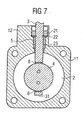
- Fig. 7 shows schematically a further embodiment of the valve component set, wherein the shaft 3 is connected only via a bearing device 5 to the housing 6.
- the holder or attachment of the shaft 3 takes place only in a region of the housing 6, while the other end 31 of the shaft 3 is free.
- the shaft 3 extends over the cross section 20 of the inner channel 1, so that it also has two grooves 8, which serve to align with the jacket tube 9 of the inner channel 1.
- Such an embodiment of the valve shaft with flap 4 has the advantage that the production is cheaper due to the omission of the second bearing device (not shown).
- the flow resistance generated by the shaft 3 is reduced.
- the shaft 3 and the flap 4 are made in one piece, in particular they were sintered from the same material and in one process step.
- valve component set which can also be aligned later exactly to a subsequent component, the preferred embodiment with at least one matching the inner channel 1 groove 8 on the shaft 3 is particularly inexpensive to produce.
Abstract
Description
Die Erfindung betrifft einen Ventilkomponentensatz zum Verschließen eines Innenkanals, der in einer Strömungsleitung angeordnet ist, mit einer Klappe, die mit einer Welle verbunden ist, mit einer Lagervorrichtung für die Welle und mit einem Gehäuse, wobei die Welle Mittel zur Positionierung der Klappe gegenüber dem Innenkanal aufweist. Ein solcher Ventilkomponentensatz eignet sich insbesondere zur Steuerung oder Regelung von Abgasströmen in einem mobilen Abgasreinigungssystem.The invention relates to a valve component set for closing an inner channel, which is arranged in a flow line, with a flap which is connected to a shaft, with a bearing device for the shaft and with a housing, wherein the shaft means for positioning the flap relative to the inner channel having. Such a valve component set is particularly suitable for controlling or regulating exhaust gas streams in a mobile exhaust gas purification system.
Angetrieben durch immer schärfere Abgasbestimmungen wurde insbesondere für Personenkraftwagen die Entwicklung von Abgasrückführungssystemen vorangetrieben. Grundsätzlich hat ein derartiges System die Aufgabe eine bestimmte Menge des in einer Verbrennungskraftmaschine erzeugten Abgases in ein bereitgestelltes Luft-Treibstoff-Gemisch einzuleiten, um auf diese Weise eine Reduzierung der gebildeten Stickoxide zu erreichen. Beim Verbrennungsprozess werden Kohlenwasserstoffe, wie sie beispielsweise in Benzin, Diesel oder dergleichen enthalten sind, mit dem Sauerstoff der Luft in Kohlendioxid und Wasser umgewandelt. Dabei reagiert allerdings auch der in der Luft enthaltene Stickstoff mit dem Sauerstoff, wobei Stickoxide entstehen. Dabei ist es bekannt, dass bei niedrigeren Temperaturen bei der Verbrennung weniger Stickoxide entstehen. Die Folgen einer hohen Stickoxidemission sind beispielsweise eine geringere Effizienz der Verbrennungskraftmaschine und eine erhöhte Luftverschmutzung. Aufgrund der Tatsache, dass das in die Verbrennungskraftmaschine erneut eingeleitete Abgas einen geringeren Sauerstoffgehalt enthält, steigt insgesamt der Inertgasanteil im Verbrennungsraum und die Verbrennung verlangsamt sich unter Absenkung der Stickoxid-Emission. Führt man beispielsweise ca. 10 % des Abgasstromes wieder in die Verbrennungskraftmaschine zurück, lässt sich eine Stickoxidabsenkung von ca. 30 % erreichen.Driven by ever stricter exhaust regulations, the development of exhaust gas recirculation systems has been pushed forward, especially for passenger cars. Basically, such a system has the task to introduce a certain amount of the exhaust gas generated in an internal combustion engine in a provided air-fuel mixture, in order to achieve a reduction of the nitrogen oxides formed in this way. In the combustion process, hydrocarbons such as those found in gasoline, diesel or the like are converted into carbon dioxide and water with the oxygen of the air. However, the nitrogen contained in the air also reacts with the oxygen, whereby nitrogen oxides are formed. It is known that generate less nitrogen oxides at lower temperatures during combustion. The consequences of high nitrogen oxide emissions are, for example, a lower efficiency of the internal combustion engine and increased air pollution. Due to the fact that the exhaust gas reintroduced into the internal combustion engine contains a lower oxygen content, in total the proportion of inert gas in the combustion chamber increases and the combustion slows down while lowering the nitrogen oxide emission. If, for example, about 10% of the exhaust gas flow back into the internal combustion engine, a nitrogen oxide reduction of about 30% can be achieved.
Allerdings hat sich herausgestellt, dass eine Zugabe von Abgas in Abhängigkeit der thermischen und/oder thermodynamischen Bedingungen im Brennraum der Verbrennungskraftmaschine zu erfolgen hat, um einerseits einen hohen Wirkungsgrad der Verbrennung und andererseits eine geringe Stickoxidemission zu erzielen. Da die im Brennraum während der Verbrennung herrschenden Temperaturen einen wesentlichen Einflussfaktor betreffend die Stickoxid-Emission darstellen, ist es auch bekannt, das zurückgeführte Abgas vor dem Einleiten in das Luft-Treibstoff-Gemisch aktiv zu kühlen, und auf diese Weise die Temperatur im Brennraum zu senken.However, it has been found that an addition of exhaust gas must take place as a function of the thermal and / or thermodynamic conditions in the combustion chamber of the internal combustion engine, on the one hand to achieve high combustion efficiency and, on the other hand, low nitrogen oxide emission. Since the temperatures prevailing in the combustion chamber during combustion represent a significant factor influencing the nitrogen oxide emission, it is also known to actively cool the recirculated exhaust gas before it is introduced into the air-fuel mixture, and thus in the combustion chamber to the temperature reduce.
Um derartige Regulierungsmöglichkeiten zu gewährleisten, sind Abgassysteme entwickelt worden, die mehrere Abgasrückführungsleitungen aufweisen. Dabei wird das zurückzuführende Abgas in Abhängigkeit des Betriebszustandes der Verbrennungskraftmaschine direkt zu dem Ansaugrohr zurückgeführt oder zunächst über einen anderen Strang des Abgassystems zu einem Kühler geführt, in dem die Temperatur des Abgases gesenkt wird, um anschließend dieses gekühlte Abgas der Verbrennungskraftmaschine zuzuführen. Die Regulierung der zurückzuführenden Abgasströme hinsichtlich der Weiterleitung in verschiedene Abgasrückführungsstränge zu vorgebbaren Zeitpunkten erfolgt mit Doppelklappen, wie sie beispielsweise aus der DE 44 26 028 bekannt sind.In order to ensure such regulatory possibilities, exhaust systems have been developed which have a plurality of exhaust gas recirculation lines. In this case, the recirculated exhaust gas is returned as a function of the operating state of the internal combustion engine directly to the intake manifold or first passed through another strand of the exhaust system to a radiator, in which the temperature of the exhaust gas is lowered to then supply this cooled exhaust gas of the internal combustion engine. The regulation of the recirculated exhaust gas streams with respect to the forwarding in different exhaust gas recirculation strands at predetermined times is done with double flaps, as they are known for example from DE 44 26 028.
Die DE 44 26 028 betrifft ein Abgasklappensystem für eine mehrsträngige Abgasanlage. In den beiden Abgassträngen ist jeweils eine Abgasklappe vorgesehen, wobei beide Abgasklappen eine gemeinsame Schwenkachse aufweisen, und die beiden Abgasklappen um 90° gegeneinander verdreht angeordnet sind. Die beiden Abgasstränge können somit wechselweise durch die Abgasklappen verschlossen bzw. freigegeben werden. Dabei ist es besonders vorteilhaft, dass das Abgas während einer Kaltstartphase der Verbrennungskraftmaschine ungekühlt zugeführt wird, da dieses in der Kaltstartphase bekannterweise eine geringere Temperatur aufweist. Nach der Kaltstartphase wird das zurückzuführende Abgas durch einen Strang mit einem Abgaskühler (Wärmetauscher) geleitet, um die oben beschriebenen positiven Effekte in Hinblick auf die Stickoxidemission zu erzielen. Die Abgaskühler sind dabei bekanntermaßen so aufgebaut, dass sie den jeweiligen Abgasstrang umschließen, wobei ein Kühlmittel, wie beispielsweise Wasser oder Luft, von diesem durchströmt wird.DE 44 26 028 relates to an exhaust gas flap system for a multi-line exhaust system. In each case an exhaust flap is provided in the two exhaust gas lines, wherein both exhaust gas flaps have a common pivot axis, and the two exhaust gas flaps are arranged rotated by 90 ° to each other. The two exhaust lines can thus be alternately closed or released by the exhaust valves. It is particularly advantageous that the exhaust gas is supplied uncooled during a cold start phase of the internal combustion engine, since this is known to have a lower temperature in the cold start phase. After the cold start phase is the recirculated exhaust gas through a strand with an exhaust gas cooler (heat exchanger) passed to achieve the above-described positive effects in terms of nitrogen oxide emission. The exhaust gas coolers are known to be constructed so that they surround the respective exhaust system, wherein a coolant, such as water or air, is flowed through by this.
Da eine solche mehrsträngige Abgasrückführungsleitung relativ viel Platz benötigt, was insbesondere in Hinblick auf die Anordnung einer solchen Abgasrückführungsleitung im Motorraum eines Personenkraftwagens Probleme verursacht, wurden neue Abgaskühler entwickelt. Diese Abgaskühler zeichnen sich dadurch aus, dass sie in ihrem Inneren zweisträngig aufgebaut sind, wobei das den Abgaskühler durchströmende Abgas in einem Strang gekühlt wird, während es in einer anderen Leitung ungekühlt hindurchgeführt wird. Solche neuen Abgaskühler weisen im Zentrum einen Innenkanal auf, der bevorzugt konzentrisch von einer ringförmigen Strömungsleitung umgeben ist. Die ringförmige Strömungsleitung steht im wärmeleitenden Kontakt mit einem äußeren Mantel, von außen mit einem Kühlmedium umspült wird. Folglich wird das Abgas beim Durchströmen der Strömungsleitung gekühlt. Wird das Abgas über den Innenkanal zurückgeführt, behält dieses seine Temperatur im wesentlichen bei, da ein direkter und wärmeleitender Kontakt zur Mantelfläche der Strömungsleitung unterbunden ist.Since such a multi-strand exhaust gas recirculation line requires a relatively large amount of space, which causes problems in particular with regard to the arrangement of such exhaust gas recirculation line in the engine compartment of a passenger car, new exhaust gas coolers have been developed. These exhaust gas coolers are characterized in that they are constructed in two-stranded in its interior, wherein the exhaust gas flowing through the exhaust gas is cooled in one strand, while it is passed uncooled in another line. Such new exhaust gas cooler have in the center an inner channel, which is preferably surrounded concentrically by an annular flow line. The annular flow line is in heat-conducting contact with an outer jacket, is surrounded by a cooling medium from the outside. Consequently, the exhaust gas is cooled as it flows through the flow line. If the exhaust gas is returned via the inner channel, this essentially retains its temperature, since a direct and heat-conducting contact with the lateral surface of the flow line is prevented.
Aus der DE 43 10 538 A und der US-B1-6 178 744 ist ein Ventilkomponentensatz der eingangs genannten Art bekannt.From DE 43 10 538 A and US-B1-6 178 744 a valve component set of the type mentioned is known.
Aus der JP 11 35 14 16 A ist ein Klappenventil der eingangs genannten Art bekannt. Dabei ist der Querschnitt der Teile der Welle, die in kreisrunden Ausnehmungen im Mantelrohr des Durchflußkanals drehbar gelagert sind, oval ausgebildet. Über einen Zufuhrschlitz, der eine Breite entsprechend der geringsten Breite des Ovals besitzt, ist die Welle in die kreisrunde Ausnehmung im Mantelrohr einführbar und in ihre Arbeitsposition verdrehbar. In dem Bereich ihrer Arbeitsposition ist die Welle über die größte Erstreckung ihres Ovals drehbar in der Ausnehmung im Mantelrohr geführt.From JP 11 35 14 16 A, a flap valve of the type mentioned is known. In this case, the cross section of the parts of the shaft which are rotatably mounted in circular recesses in the jacket tube of the flow channel, oval shaped. About a feed slot having a width corresponding to the smallest width of the oval, the shaft is inserted into the circular recess in the jacket tube and in their Work position rotatable. In the region of its working position, the shaft is rotatably guided over the largest extent of its oval in the recess in the jacket tube.
Aus der WO 99/54612 A ist eine in einer Abgasleitung eines Fahrzeugs mit Brennkraftmaschine angeordnete Bremsvorrichtung bekannt, die eine auf einer drehbaren Welle angeordnete Klappe aufweist, durch die ein Durchtrittskanal absperrbar ist.From WO 99/54612 A a arranged in an exhaust pipe of a vehicle with internal combustion engine braking device is known which has a valve disposed on a rotatable shaft flap, through which a passageway can be shut off.
Aus der US-A-3 693 935 ist eine einseitige Lagerung einer Drosselklappenwelle in einer Abgasleitung eines Verbrennungsmotors bekannt. Dabei besteht der Lagerkörper zur Lagerung der Drosselklappenwelle aus einer Hohlschraube, die in eine Gewindebohrung in der Wand der Abgasleitung einschraubbar ist.From US-A-3 693 935 a one-sided mounting of a throttle shaft in an exhaust pipe of an internal combustion engine is known. In this case, the bearing body for supporting the throttle shaft consists of a hollow screw which can be screwed into a threaded bore in the wall of the exhaust pipe.
Hiervon ausgehend ist es Aufgabe der vorliegenden Erfindung, Mittel zur Steuerung bzw. Regulierung von Fluidströmen anzugeben, so dass eine unterschiedliche Anströmung von zwei zueinander konzentrisch angeordneten Strömungskanälen gewährleistet wird. Diese sollen dabei möglichst einfach aufgebaut, montagefreundlich (insbesondere in Hinblick auf die Nachrüstung und Kombination derartiger neuer Abgaskühler bei bekannten Abgasrückführungsleitungen) und preiswert ausgeführt sein.On this basis, it is an object of the present invention to provide means for controlling or regulating fluid flows, so that a different flow is ensured by two mutually concentric flow channels. These should be as simple as possible, easy to install (especially with regard to the retrofitting and combination of such new exhaust gas cooler in known exhaust gas recirculation lines) and low cost.
Diese Aufgaben werden gelöst durch einen Ventilkomponentensatz mit den Merkmalen des Anspruchs 1. Weitere vorteilhafte Ausgestaltungen der Erfindung, welche einzeln oder in Kombination miteinander eingesetzt werden können, sind Gegenstand der jeweils abhängigen Ansprüche.These objects are achieved by a valve component set with the features of claim 1. Further advantageous embodiments of the invention, which can be used individually or in combination with each other, are the subject of the respective dependent claims.
Die mindestens eine Nut dient zur Positionierung gegenüber dem Mantelrohr, wobei dieses zumindest teilweise in die Nut eingreift. Auf diese Weise wird eine exakte Ausrichtung der Klappe gegenüber dem den Innenkanal begrenzenden Mantelrohr sichergestellt, so dass insbesondere Montagetoleranzen oder Fertigungstoleranzen ausgeglichen werden, wie sie beispielsweise in Hinblick auf die konzentrische Anordnung des Mantelrohres gegenüber der Strömungsleitung oder aber der Welle bezüglich der Lagerung im Gehäuse auftreten.The at least one groove serves for positioning relative to the jacket tube, this at least partially engaging in the groove. In this way, an exact alignment of the flap with respect to the inner channel limiting jacket tube is ensured so that in particular assembly tolerances or manufacturing tolerances are compensated, as for example with regard to the concentric arrangement of the jacket tube relative to the flow line or the shaft with respect to the storage in the housing occur.
Die Aussparung, die bevorzugt als Langloch ausgeführt ist, dient dabei zumindest abschnittsweise als Anlagefläche für die Welle. Diese anliegenden Abschnitte sollten jedoch kleiner als 50 %, insbesondere kleiner als 30 %, vorzugsweise kleiner als 10 % des Umfangs der Welle ausmachen, um gegebenenfalls unterschiedliches thermisches Ausdehnungsverhalten der Welle gegenüber dem Mantelrohr zu gewährleisten. Auch kann es unter Umständen vorteilhaft sein, dass eine gewisse Bewegungsfreiheit der Welle in der Aussparung ermöglicht wird, so dass Verunreinigungen wie Rußpartikel, Asche oder dergleichen, die sich während des Betriebes einer solchen Abgasrückführungseinrichtung in der Aussparung festsetzen können, aufgrund dieser Relativbewegung wieder gelöst werden. Dadurch wird insbesondere eine Beeinträchtigung der Rotationsfreiheit der Welle durch Verklebung verhindert.The recess, which is preferably designed as a slot, thereby serves at least partially as a contact surface for the shaft. However, these adjoining sections should make up less than 50%, in particular less than 30%, preferably less than 10% of the circumference of the shaft, in order to ensure, if appropriate, different thermal expansion behavior of the shaft relative to the jacket tube. It may also be advantageous under certain circumstances that a certain freedom of movement of the shaft is made possible in the recess, so that impurities such as soot particles, ash or the like, which can settle in the recess during operation of such exhaust gas recirculation device, are released again due to this relative movement , As a result, in particular an impairment of the rotational freedom of the shaft is prevented by bonding.
Hinsichtlich der Ausgestaltung der Aussparung als Langloch sei noch darauf hingewiesen, dass die offene Seite des Langloches bevorzugt in entgegengesetzte Richtung zur Strömungsrichtung angeordnet ist, so dass die Welle stets mit dem durchströmenden Fluid in die Aussparung hineingedrückt wird. Ungeachtet dessen besteht jedoch die Möglichkeit, derartige Ventilkomponentensätze auf der Eintrittsseite oder auf der Austrittsseite des Innenkanals anzuordnen. Wird der Ventilkomponentensatz mit einem Abgaskühler verbunden, wie er oben beschrieben ist, so hat die Anordnung auf der Abgaseintrittsseite den Vorteil, dass an dieser Stelle das rückzuführende Abgas noch eine sehr hohe Temperatur aufweist, so dass Verschmutzungen oder beispielsweise Kondensation nahezu vermieden werden können. Allerdings führt die hohe Temperatur des rückzuführenden Abgases zu einer hohen thermischen Beanspruchung des Ventilkomponentensatzes, so dass es unter Umständen auch vorteilhaft sein kann, diesen auf der Fluidaustrittsseite anzuordnen. In diesem Fall sind eventuell besonders geformte Aussparungen zu verwenden, die ein Herausdrücken der Welle verhindern, oder es können zusätzliche Sicherungsmaßnahmen getroffen werden.With regard to the configuration of the recess as a slot should also be noted that the open side of the elongated hole is preferably arranged in the opposite direction to the flow direction, so that the shaft is always pressed with the fluid flowing through into the recess. Regardless, however, it is possible to arrange such valve component sets on the inlet side or on the outlet side of the inner channel. If the valve component set is connected to an exhaust gas cooler, as described above, the arrangement on the exhaust gas inlet side has the advantage that at this point the exhaust gas to be recirculated still has a very high temperature, so that contamination or, for example, condensation can be almost avoided. However, the high temperature of the exhaust gas to be recirculated leads to a high thermal stress on the valve component set, so that under some circumstances it may also be advantageous to arrange it on the fluid outlet side. In this case may be specially shaped To use recesses, which prevent the shaft from being pushed out, or additional security measures can be taken.
Die Klappe hat eine Fläche, die kleiner als der freie Strömungsquerschnitt der Strömungsleitung ist und im Wesentlichen dem Querschnitt des Innenkanals entspricht, so dass mittels der Klappe der Innenkanal geöffnet oder geschlossen werden kann, wobei der Strömungsquerschnitt variiert wird. Ein solcher Ventilkomponentensatz kann auch nachträglich exakt zu einem anschließenden Bauteil (wie beispielsweise einem Abgaskühler mit interner Bypass-Strömung oder der Abgasrückführungsleitung) ausgerichtet werden, wobei zusätzlich Montagefehler vermieden werden. Außerdem ist gewährleistet, dass geringe Abweichungen hinsichtlich der Positionierung der Ventilklappe zum Innenkanal, wie sie beispielsweise infolge von Fertigungstoleranzen auftreten, ausgeglichen werden können.The flap has an area which is smaller than the free flow cross section of the flow line and essentially corresponds to the cross section of the inner channel, so that the inner channel can be opened or closed by means of the flap, wherein the flow cross section is varied. Such a valve component set can also be aligned later exactly to a subsequent component (such as an exhaust gas cooler with internal bypass flow or the exhaust gas recirculation line), in addition assembly errors are avoided. In addition, it is ensured that small deviations in the positioning of the valve flap to the inner channel, as they occur, for example, due to manufacturing tolerances, can be compensated.
In Hinblick auf eine gleichmäßige Verteilung des durchströmenden Fluids ist es vorteilhaft, dass der Innenkanal zur Strömungsleitung im wesentlichen konzentrisch angeordnet ist. Auf diese Weise ist bei einer zentralen Anströmung gewährleistet, dass der Innenkanal keinen Strömungswiderstand darstellt und turbulente Strömungen vermieden werden.With regard to a uniform distribution of the fluid flowing through, it is advantageous that the inner channel to the flow line is arranged substantially concentric. In this way, it is ensured with a central flow that the inner channel is not a flow resistance and turbulent flows are avoided.
Gemäß einer weiteren Ausgestaltung hat das Gehäuse einen Flansch, wobei die Lagervorrichtung der Welle über eine Wärmebrücke mit dem Flansch verbunden ist. Der Flansch dient insbesondere zur Montage des Gehäuses an einen Abgaskühler, wobei dieser naturgemäß eine deutlich reduzierte Temperatur gegenüber dem Abgasstromes aufweist, der das Gehäuse durchströmt. Durch die Bildung einer Wärmebrücke zwischen der Lagervorrichtung und dem Flansch ist ein schneller Abtransport der in die Lagervorrichtung eingebrachte Wärme (beispielsweise über die Welle oder das Abgas direkt) sichergestellt. Dies führt zu einer deutlich erhöhten Lebensdauer in Hinblick auf die Funktionalität des Lagers. Die Lebensdauer kann zusätzlich durch die Verwendung einer Graphitschmierung oder aber eines Graphit enthaltenden Lagersitzes gesteigert werden.According to a further embodiment, the housing has a flange, wherein the bearing device of the shaft is connected via a thermal bridge with the flange. The flange is used in particular for mounting the housing to an exhaust gas cooler, wherein this naturally has a significantly reduced temperature compared to the exhaust gas stream, which flows through the housing. The formation of a thermal bridge between the bearing device and the flange ensures rapid removal of the heat introduced into the bearing device (for example via the shaft or the exhaust gas directly). This leads to a significantly increased service life with regard to the functionality of the bearing. The life span can additionally be increased by the use of a graphite or a graphite bearing seat containing graphite.
Gemäß noch einer weiteren Ausgestaltung ist ein Durchmesser der Strömungsleitung in Strömungsrichtung eines durchströmenden Fluid kleiner oder gleich einem angrenzenden Öffnungsdurchmesser eines angrenzenden Bauteils. Auf diese Weise werden sogenannte Abrisskanten am Umfang der Strömungsleitung vermieden, welche zu einer turbulenten Strömung des Fluids führen würden. Eine solche turbulente Strömung hätte zur Folge, dass eine exakte Steuerung bzw. Regulierung des Fluidstromes nicht mehr gewährleistet wäre. Dabei gelten die gerade beschriebenen Beziehungen bei einer Anordnung des Ventilkomponentensatzes stromaufwärts des angrenzenden Bauteils (zum Beispiel eines Abgaskühlers). Ist der Ventilkomponentensatz stromabwärts des angrenzenden Bauteils angeordnet, so ist der Außendurchmesser der Strömungsleitung in Strömungsrichtung des durchströmenden Fluids größer oder gleich dem angrenzenden Öffnungsdurchmesser des angrenzenden Bauteils ausgeführt. Auf diese Weise wird vermieden, dass Teile des stromabwärts angeordneten Bauteils in den freien Strömungsquerschnitt der Strömungsleitung hineinragen und zur Verwirbelung des Fluids führen.According to yet another embodiment, a diameter of the flow line in the flow direction of a fluid flowing through is smaller than or equal to an adjacent opening diameter of an adjacent component. In this way, so-called demolition edges are avoided at the periphery of the flow line, which would lead to a turbulent flow of the fluid. Such a turbulent flow would mean that an exact control or regulation of the fluid flow would no longer be guaranteed. In this case, the relationships just described in an arrangement of the valve component set apply upstream of the adjacent component (for example, an exhaust gas cooler). If the valve component set is arranged downstream of the adjacent component, then the outer diameter of the flow line in the flow direction of the fluid flowing through is made greater than or equal to the adjacent opening diameter of the adjacent component. In this way it is avoided that parts of the downstream component protrude into the free flow cross-section of the flow line and lead to turbulence of the fluid.
Betrachtet man die Anordnung der Klappe quer zur Strömungsrichtung, so wird zwischen der Klappe und dem Mantelrohr des Innenkanals ein Ringspalt gebildet, der seinen Ursprung insbesondere in der nachträglichen Positionierung der Klappe in dem Mantelrohr hat. Dies hat nämlich zur Folge, dass die Klappe gegenüber dem Mantelrohr mit ausreichend großen Montagetoleranzen versehen werden muss, so dass eine exakte Positionierung der Klappe gegenüber dem Mantelrohr innerhalb vorgebbarer Grenzen gewährleistet ist. Der Ringspalt ist dabei vorteilhafterweise so ausgebildet, dass nur eine Bypass-Strömung von weniger als 5 %, insbesondere weniger 3 %, bevorzugt sogar kleiner 1% des in das Gehäuse einströmenden Fluides erlaubt wird, das folglich größtenteils durch die Strömungsleitung hindurchströmt.Considering the arrangement of the flap transversely to the flow direction, an annular gap is formed between the flap and the jacket tube of the inner channel, which has its origin in particular in the subsequent positioning of the flap in the jacket tube. This has the consequence that the flap relative to the jacket tube must be provided with sufficiently large mounting tolerances, so that an exact positioning of the flap over the jacket tube is ensured within predeterminable limits. The annular gap is advantageously designed so that only a bypass flow of less than 5%, in particular less than 3%, preferably even less than 1% of the fluid flowing into the housing is allowed, which consequently flows largely through the flow line.
Bei einer Anordnung der Klappe quer zur Strömungsrichtung wird das Ziel verfolgt, eine Durchströmung des Fluids durch den Innenkanal zu verhindern. Der Ringspalt hat jedoch zur Folge, dass dennoch eine Bypass-Strömung durch den Innenkanal hindurchströmt. Werden jedoch maximale Bypass-Strömungen von 5 % gewährleistet, so lassen sich in Hinblick auf die Durchströmung eines Abgaskühlers immer noch sehr exakt vorgebbare Temperaturbereiche des gekühlten Abgasstromes erzielen, ohne die Effektivität des Abgaskühlers spürbar zu beeinträchtigen.In an arrangement of the flap transverse to the flow direction, the aim is to prevent a flow of fluid through the inner channel. However, the annular gap has the consequence that nevertheless a bypass flow flows through the inner channel. However, if maximum bypass flows of 5% are guaranteed, it is still possible to achieve very precisely predeterminable temperature ranges of the cooled exhaust gas flow with regard to the flow through an exhaust gas cooler, without noticeably impairing the effectiveness of the exhaust gas cooler.
Zur Erzielung einer solch begrenzten Bypass-Strömung ist es vorteilhaft, dass der Ringspalt eine Breite hat, die kleiner als 0,5 mm ist, bevorzugt kleiner als 0,3 mm und insbesondere kleiner als 0,15 mm. Dabei ist insbesondere die breiteste Stelle des Ringspalts gemeint, falls eine exakte zentrische Anordnung der Klappe zu dem Mantelrohr nicht erreicht werden kann.In order to achieve such a limited bypass flow, it is advantageous that the annular gap has a width which is smaller than 0.5 mm, preferably smaller than 0.3 mm and in particular smaller than 0.15 mm. In this case, in particular the widest point of the annular gap is meant, if an exact centric arrangement of the flap to the jacket tube can not be achieved.
Gemäß noch einer weiteren Ausgestaltung weist die Klappe eine Fläche auf, die gegenüber dem Querschnitt des Innenkanals verschieden ist. Hierbei ist sowohl der Flächeninhalt, also die Größe der Fläche, sowie auch die Form oder äußere Gestalt der Fläche gemeint. So ist es beispielsweise vorteilhaft, bei einem kreisrunden Querschnitt des Innenkanals die Klappe mit einer ovalen Fläche auszuführen, wobei die Klappe in der verschließenden Stellung nicht senkrecht zur Strömungsrichtung ausgerichtet ist, sondern mit dieser einen anderen Winkel bildet. Dies hat zur Folge, dass unter Umständen ein sehr kleiner Ringspalt gebildet ist, der bevorzugt nicht umläuft, sondern durch mehrere Bereiche unterbrochen wird, indem die Klappe an dem Mantelrohr anliegt. Das hat weiterhin den Vorteil, dass der verbleibende Ringspalt nicht direkt angeströmt werden kann, und somit eine unerwünschte Bypass-Strömung nahezu vermieden wird.According to yet another embodiment, the flap has a surface which is different from the cross section of the inner channel. In this case, both the area, ie the size of the area, as well as the shape or external shape of the area meant. Thus, it is advantageous, for example, to carry out the flap with an oval surface in the case of a circular cross-section of the inner channel, the flap not being oriented perpendicular to the flow direction in the closing position, but forming a different angle with the latter. This has the consequence that under certain circumstances, a very small annular gap is formed, which preferably does not rotate, but is interrupted by several areas by the flap rests against the jacket tube. This has the further advantage that the remaining annular gap can not be directly flowed, and thus an undesirable bypass flow is almost avoided.
Gemäß noch einer weiteren Ausgestaltung ist die Welle mit einem Antrieb so verbunden, dass die Welle mittels des Antriebes frei rotierbar ist. Das hat zur Folge, dass die Klappe in beliebig wählbaren Positionen fixiert werden kann, so dass neben der geschlossenen Stellung, in der nahezu keine Bypass-Strömung stattfindet, und einer geöffneten Stellung, in der ein möglichst großer Anteil der Bypass-Strömung durch den Innenkanal strömt, auch jede weitere Zwischenstellung der Klappe einstellbar ist. Die hieraus resultierenden unterschiedlichen Strömungsverhältnisse im Inneren eines Abgaskühlers erlauben eine exakte Anpassung der Temperatur des rückgeführten Abgases an die aktuell vorliegenden Bedingungen im Brennraum der Verbrennungskraftmaschine.According to yet another embodiment, the shaft is connected to a drive so that the shaft is freely rotatable by means of the drive. This has the consequence that the flap can be fixed in arbitrarily selectable positions, so that in addition to the closed position in which almost no bypass flow takes place, and an open position in which the largest possible proportion of the bypass flow through the inner channel flows, also every other intermediate position of the flap is adjustable. The resulting different flow conditions in the interior of an exhaust gas cooler allow an exact adjustment of the temperature of the recirculated exhaust gas to the currently existing conditions in the combustion chamber of the internal combustion engine.
Gemäß noch einer weiteren Ausgestaltung weist die Lagervorrichtung und/oder das Gehäuse eine Dichtung auf, welche vorzugsweise aus Graphit hergestellt ist und die Strömungsleitung gegenüber der Umgebung außerhalb des Gehäuses abdichtet. Graphit hat sich überraschenderweise als Dichtmittel herausgestellt, obwohl bislang davon ausgegangen wurde, dass Graphit nur eine thermische Stabilität bis ca. 450 °C aufweist. Ein Einsatz als Dichtmittel im Abgassystem wurde bislang nicht in Betracht gezogen, da sich wegen des das Gehäuse durchströmenden Abgases thermische Beanspruchungen bis ca. 700 °C ergeben. Ein Grund dafür, dass eine Dichtung, die zumindest teilweise aus Graphit (insbesondere Graphitfolie) besteht, bei derartig hohen Temperaturen ihre Funktionalität beibehält, ist in dem hohen Inertgas-Anteil des vorbeiströmenden Abgases zu sehen. Gelangt das heiße Abgas zur Dichtstelle oder zur Lagerung so hat der Kontakt mit dem Graphit eine erhöhte thermische Stabilität des Graphits zur Folge. Ist die Dichtung beispielsweise mit einer Graphitfolie gebildet, welche zu einem Ring geformt ist und über die Achse gestülpt wird. Dabei wird dieser Ring mit Graphitfolie vorzugsweise mittels der Lagervorrichtung gegen einen Anschlag des Gehäuses gedrückt, so dass es zu einer Verformung der Graphitfolie bzw. des Ringes kommt. Diese Verformung wirkt nun wie eine Art Labyrinthdichtung, so dass ein Ausströmen des Abgases aus dem Gehäuse in die Umgebung dauerhaft verhindert wird. Die Graphit-Dichtung steht nun von einer Seite mit dem nahezu sauerstofflosen Abgas in Kontakt, während auf der anderen Seite durch die Hülse und dem erhöhtem Druck in der Abgasanlage ein schädliches Eindringen von Luft vermieden wird.According to yet another embodiment, the bearing device and / or the housing on a seal, which is preferably made of graphite and the flow line seals against the environment outside of the housing. Graphite has surprisingly been found to be a sealant, although it was previously assumed that graphite has only a thermal stability up to about 450 ° C. A use as a sealant in the exhaust system has not been considered, because due to the exhaust gas flowing through the housing thermal stresses up to about 700 ° C result. One reason why a gasket that is at least partially made of graphite (especially graphite foil) maintains its functionality at such high temperatures is seen in the high inert gas content of the passing exhaust gas. If the hot exhaust gas reaches the sealing point or storage, contact with the graphite results in increased thermal stability of the graphite. For example, if the gasket is formed with a graphite foil which is formed into a ring and slipped over the axis. In this case, this ring is pressed with graphite foil preferably by means of the bearing device against a stop of the housing, so that there is a deformation of the graphite foil or the ring. This deformation now acts as a kind of labyrinth seal, so that an outflow the exhaust gas is permanently prevented from the housing in the environment. The graphite seal is now in contact with the nearly oxygen-free exhaust gas from one side, while on the other side through the sleeve and the increased pressure in the exhaust system a harmful ingress of air is avoided.
Gemäß noch einer weiteren Ausgestaltung weist das Gehäuse einen Zugang auf, der so gestaltet ist, dass mindestens 75 %, insbesondere mindestens 85 %, bevorzugt mehr als 95 % eines in das Gehäuse einströmenden Fluids in den Innenkanal strömt, wenn die Klappe in Strömungsrichtung angeordnet ist. Eine solche Ausgestaltung des Zugangs ist insbesondere dann vorteilhaft, wenn das Gehäuse stromaufwärts eines Abgaskühlers angeordnet ist. Somit ist gewährleistet, dass das Fluid nahezu ausschließlich durch den Innenkanal strömt, wenn die Klappe in der geöffneten Stellung ist. Die Klappe und die Welle sind dabei so in Strömungsrichtung angeordnet, dass sie einen möglichst kleinen Strömungswiderstand darstellen, und insbesondere auch beim Vorbeiströmen des Fluids eine möglichst laminare Strömung beibehalten wird.According to yet another embodiment, the housing has an access that is designed so that at least 75%, in particular at least 85%, preferably more than 95% of a fluid flowing into the housing flows into the inner channel when the flap is arranged in the flow direction , Such an embodiment of the access is particularly advantageous if the housing is arranged upstream of an exhaust gas cooler. Thus, it is ensured that the fluid flows almost exclusively through the inner channel when the flap is in the open position. The flap and the shaft are arranged in the flow direction such that they represent the smallest possible flow resistance and, in particular, a laminar flow which is as laminar as possible when the fluid flows past it.
Gemäß noch einer weiteren Ausgestaltung des Ventilkomponentensatzes ist die Welle nur über eine Lagervorrichtung mit dem Gehäuse verbunden. Das bedeutet, dass sich die Welle nicht über den gesamten Strömungsquerschnitt bzw. Außendurchmesser der Strömungsleitung erstreckt, wobei die Welle und die Klappe vorzugsweise einstückig, insbesondere aus einem Material, hergestellt sind. Die Halterung bzw. Befestigung der Welle erfolgt nur noch an einem Punkt im Gehäuse, während das andere Ende der Welle frei ist. Die Welle erstreckt sich dabei bevorzugt über den Querschnitt des Innenkanals, so dass diese auch zwei Nuten hat, die zur Ausrichtung gegenüber dem Innenkanal dienen. Eine solche Ausführung der Ventilwelle mit Klappe hat die Vorteile, dass die Herstellung aufgrund des Weglassens der zweiten Lagerung preiswerter wird, außerdem wird der durch die Welle erzeugte Strömungswiderstand reduziert.According to yet another embodiment of the valve component set, the shaft is connected to the housing only via a bearing device. This means that the shaft does not extend over the entire flow cross-section or outer diameter of the flow line, wherein the shaft and the flap are preferably made in one piece, in particular of a material. The mounting or attachment of the shaft takes place only at one point in the housing, while the other end of the shaft is free. The shaft preferably extends over the cross section of the inner channel, so that it also has two grooves, which serve to align with the inner channel. Such an embodiment of the valve shaft with flap has the advantages that manufacturing due The omission of the second storage is cheaper, also the flow resistance generated by the shaft is reduced.
Die Erfindung wird nachfolgend anhand der Zeichnungen näher erläutert, wobei diese lediglich vorteilhafte und besonders bevorzugte Ausführungsformen darstellen. Die Erfindung ist nicht auf die dargestellten Ausführungsbeispiele beschränkt. Es zeigen schematisch:
- Fig. 1
- perspektivisch eine erste Ausführungsform des Ventilkomponentensatzes im montierten Zustand,
- Fig. 2
- eine weitere Ansicht der Ausführungsform aus Fig 1,
- Fig. 3
- schematisch und perspektivisch eine Detailansicht einer Ausführungsform des Ventilkomponentensatzes,
- Fig. 4
- eine Detailansicht einer Ausführungsform des Ventilkomponentensatzes in der geschlossenen Position;
- Fig. 5
- die Ausführungsform aus Fig. 4 in einer geöffneten Position;
- Fig. 6
- eine Schnittansicht einer weiteren Ausführungsform des Ventilkomponentensatzes und
- Fig. 7
- eine Schnittansicht einer weiteren Ausführungsform eines Ventilkomponentensatzes mit verkürzter Welle.
- Fig. 1
- in perspective a first embodiment of the valve component set in the mounted state,
- Fig. 2
- another view of the embodiment of Figure 1,
- Fig. 3
- schematically and in perspective a detailed view of an embodiment of the valve component set,
- Fig. 4
- a detail view of an embodiment of the valve set in the closed position;
- Fig. 5
- the embodiment of Figure 4 in an open position.
- Fig. 6
- a sectional view of another embodiment of the valve component set and
- Fig. 7
- a sectional view of another embodiment of a valve component set with shortened shaft.
Figur 1 zeigt schematisch und perspektivisch eine erste Ausführungsform des erfindungsgemäßen Ventilkomponentensatzes zum Verschließen eines Innenkanals 1, der in einer Strömungsleitung 2 angeordnet ist. In der dargestellten Ausführungsform wird die Strömungsleitung 2 in eine Mehrzahl von Teilströmungen unterteilt. Der Ventilkomponentensatz zeichnet sich dadurch aus, dass dieser eine mit einer Welle 3 verbundene Klappe 4, eine Lagervorrichtung 5 und ein Gehäuse 6 (nicht dargestellt) umfasst, wobei die Welle 3 Mittel zur Positionierung der Klappe 4 gegenüber dem Innenkanal 1 aufweist. Der Innenkanal 1 ist in der dargestellten Ausführungsform im wesentlichen konzentrisch zur Strömungsleitung 2 angeordnet.Figure 1 shows schematically and in perspective a first embodiment of the valve component set according to the invention for closing an inner channel 1, which is arranged in a
Als Mittel zur Positionierung weist die Welle 3 zwei Nuten 8 auf, die zur Aufnahme eines den Innenkanal 1 umgebenden Mantelrohres 9 geeignet sind. Das Mantelrohr 9 weist hierbei zwei Aussparungen 10 auf, die als Langlöcher ausgeführt sind, wobei die Aussparungen 10 jeweils in eine Nut 8 der Welle 3 eingreifen. Auf diese Weise ist sichergestellt, dass die Klappe 4 zentrisch zum Innenkanal 1 bzw. dem Mantelrohr 9 ausgerichtet ist. Die Nuten 8 dienen somit auch zur Justierung der Klappe 4 in Richtung einer Achse 29, indem die Nuten 8 in die Aussparungen 10 eingreifen. Die Ausführung der Aussparungen 10 als Langlöcher hat zudem den Vorteil, dass ein unterschiedliches thermisches Ausdehnungsverhalten des Mantelrohres 9 und der Ventilkomponentensatzes in dieser Verbindungsstelle zumindest teilweise kompensiert werden kann. Somit können insbesondere thermische Spannungen in dieser Verbindungsstelle zumindest in Richtung der Längsachse der Langlöcher bzw. in Strömungsrichtung 14 des Fluides reduziert oder sogar vermieden werden. Dies gewährleistet die Funktionstüchtigkeit des Ventilkomponentensatzes auch bei eines thermischen Wechselbeanspruchung, wie sie beispielsweise in der Abgasrückführungsleitung eines Automobils auftritt.As a means for positioning, the
Der Ventilkomponentensatz mit einem stromabwärts angeordneten Bauteil 16 (Abgaskühler) verbunden. Das als Abgaskühler ausgeführte Bauteil 16 ist von einem Kühlmittel durchströmbar, wobei in der Darstellung eine Kühlmittelzufuhr 26 zu erkennen ist, die nahe dem Ventilkomponentensatz angeordnet ist. Die Zufuhr des Kühlmittels nahe der Einströmseite gewährleistet einen großen Temperaturunterschied des Kühlmediums (Wasser, Luft oder dergleichen) gegenüber dem noch sehr heißen Abgas, so dass eine rasche Abkühlung sichergestellt ist.The valve component set is connected to a downstream component 16 (exhaust gas cooler). The designed as an exhaust gas
Die Klappe 4 ist über die Welle 3 mit einem Antrieb 7 so verbunden, dass jede beliebige Position der Klappe 4 in bezug auf die Strömungsrichtung 14 (nicht dargestellt) des durchströmenden Fluids ermöglicht wird. Vorliegend ist die Klappe 4 in der geöffneten Position dargestellt (parallel zur Strömungsrichtung 14), so dass das einströmende Fluid im wesentlichen durch den Innenkanal 1 strömt. Diese geöffnete Position der Klappe 4 wird bevorzugt in der Kaltstartphase eines Verbrennungsmotors eingenommen, so dass das Abgas den Abgaskühler ungekühlt durch den Innenkanal 1 durchströmt und der Verbrennungskraftmaschine im heißen Zustand zugeführt wird. Wird die Klappe 4 in eine geschlossene Position bewegt, so dass sie im wesentlichen senkrecht zur Strömungsrichtung 14 (nicht dargestellt) angeordnet ist und den Innenkanal 1 verschließt, strömt das Fluid nahezu vollständig durch die Strömungsleitung 2. Dabei steht das Fluid in intensivem Kontakt mit einem Mantel 30 des Abgaskühlers, wodurch eine effektive Kühlung des Abgases auf einen vorgebbaren Temperaturbereich gewährleistet ist.The
Figur 2 zeigt schematisch und perspektivisch eine Seitenansicht eines Bauteiles 16 (Abgaskühler), der in Strömungsrichtung 14 gesehen dem Ventilkomponentensatz nachgeschaltet ist. Der Ventilkomponentensatz ist in einer Montageebene 25 mit dem Bauteil 16 über einen Flansch 11 des Gehäuses 6 bevorzugt lösbar (mit bekannten Verbindungsmitteln) verbunden. An dem Gehäuse 6 ist ein Antrieb 7 befestigt, der eine Rotation der Welle 3 (nicht dargestellt) bewirkt. In dem gezeigten Ausführungsbeispiel ist der Ventilkomponentensatz so angeordnet, dass das Fluid über einen Zugang 28 in das Gehäuse 6 eingeleitet wird, wobei die Art der Durchströmung des Bauteils 16 von der Position der Klappe 4 abhängt. Der Zugang 28 des Gehäuse 6 ist so gestaltet, dass mindestens 95 % eines in das Gehäuse 6 einströmenden Fluides in den Innenkanal 1 (nicht dargestellt) strömt, wenn die Klappe 4 (nicht dargestellt) in Strömungsrichtung 14 angeordnet ist (geöffnete Position) und somit den Innenkanal 1 (nicht dargestellt) freigibt. Das an den Ventilkomponentensatz angrenzende Bauteil 16 ist als Wärmetauscher, insbesondere Abgaskühler, ausgeführt, wobei das Bauteil 16 in einem stromabwärts gelegenen Abschnitt einen Kühlmittelauslaß 27 aufweist.Figure 2 shows schematically and in perspective a side view of a component 16 (exhaust gas cooler), which is seen downstream of the valve component set in the
Figur 3 zeigt schematisch und perspektivisch eine Detailansicht, die die Positionierung der Welle 3 mit der Klappe 4 gegenüber dem Mantelrohr 9 verdeutlicht. Die Nuten 8 greifen dabei in die als Langlöcher ausgeführten Aussparungen 10 des Mantelrohres 9. Dabei ist zu erkennen, dass die Welle 3 nur in bestimmten Teilbereichen an dem Mantelrohr 9 anliegt und insbesondere in Strömungsrichtung 14 ein Spalt zwischen der Welle 3 und dem Mantelrohr 9 gebildet ist. Dieser ist vorzugsweise so zu wählen, dass eine Verschmutzung bzw. Verklebung verhindert wird, die die Rotation der Welle 3 behindern würde. Die Welle 3 ist über zwei Lagervorrichtungen 5 in einem Gehäuse 6 (nicht dargestellt) gelagert. Zur Positionierung der Welle gegenüber dem Mantelrohr 9 und dem Gehäuse 6 (nicht dargestellt) weist der Ventilkomponentensatz zusätzlich einen Sprengring 21 auf, der in bekannter Weise an einem Anschlag 22 (nicht dargestellt) des Gehäuses 6 (nicht dargestellt) fixiert wird. Die Klappe 4 kann nun beliebig rotieren, insbesondere in einem Winkel von 0° bis 90°, wobei diese Grenzwerte jeweils einen vollständig geöffneten und einen komplett verschlossenen Zustand darstellen. Dieser bevorzugte Rotationsbereich wird üblicherweise mittels installierter Endschalter begrenzt (mechanischer und/oder software-technischer Natur). Durch die Ausrichtung der Fläche 19 der Klappe 4 gegenüber der Strömungsrichtung 14 wird die Menge des den Innenkanal 1 sowie die Strömungsleitung 2 (nicht dargestellt) durchströmenden Fluids geregelt.Figure 3 shows schematically and in perspective a detail view illustrating the positioning of the
Figur 4 zeigt eine Detailansicht einer Ausführungsform des Ventilkomponentensatzes, wobei die Klappe 4 in der geschlossenen Position dargestellt ist. Zwischen der Klappe 4 und dem Mantelrohr 9 wird ein Ringspalt 17 gebildet, der nur eine Bypass-Strömung durch den Innenkanal 1 (nicht dargestellt) von weniger als 3 % erlaubt. Der überwiegende Teil des durchströmenden Fluids strömt in dieser geschlossenen Position durch die Strömungsleitung 2. Dabei weist der Ringspalt 17 eine Breite 18 auf, die bevorzugt kleiner als 0,3 mm ist.FIG. 4 shows a detailed view of an embodiment of the valve component set, wherein the
Figur 5 zeigt eine Detailansicht einer weiteren Ausführungsform des Ventilkomponentensatzes. Die Welle 3 ist nun so gedreht, dass die Klappe 4 einen größtmöglichen Querschnitt 20 des Innenkanals 1 freigibt, und nahezu der gesamte Fluidstrom durch den Innenkanal 1 hindurchströmt. In dieser Darstellung sind auch die zwei Nuten 8 deutlich zu erkennen, die zur Positionierung der Klappe 4 gegenüber dem Innenkanal 1 bzw. dem Mantelrohr 9 dienen.FIG. 5 shows a detailed view of a further embodiment of the valve component set. The
Figur 6 zeigt schematisch und in einer Schnittansicht eine weitere Ausführungsform eines Ventilkomponentensatzes. Die Welle 3 ist über die Lagervorrichtungen 5 in dem Gehäuse 6 gelagert. Zumindest nahe einer Lagervorrichtung 5 ist eine Dichtung 23 angeordnet, die vorzugsweise aus Graphit hergestellt ist und die Strömungsleitung 2 gegenüber der Umgebung 24 außerhalb des Gehäuses 6 abdichtet. Die Dichtung 23 wird mittels der Lagervorrichtungen 5 gegen das Gehäuse 5 verpresst und dabei bevorzugt auch etwas verformt bzw. gestaucht um sicherzustellen, dass eine möglichst vollständige Abdichtung erfolgt. Mit etwas axialem Spiel wird die Lagervorrichtung 5 mittels einem Sprengring 21 gesichert, wobei der Sprengring 21 gegen einen Anschlag 22 des Gehäuses 6 gepresst wird. Zusätzlich ist wird die Lagervorrichtung 5 und die Dichtung 23 von einer Buchse 32 geschützt. Diese gewährleistet beispielsweise, dass eine Dichtung 23 aus Graphit bis zu Temperaturen von 1300°C beständig bleibt, da ein Kontakt des Graphits mit Sauerstoff der Luft vermieden wird.FIG. 6 shows schematically and in a sectional view a further embodiment of a valve component set. The
Das Gehäuse 6 hat einen Flansch 11, der mit der Lagervorrichtung 5 über eine Wärmebrücke 12 verbunden ist. Die Wärmebrücke 12 zeichnet sich durch eine besonders gute Wärmeleitfähigkeit aus, so dass die über die Welle in die Lagervorrichtung 5 eingebrachte Wärme des Abgases schnell abgeführt wird und somit die Langlebigkeit der Lagervorrichtung 5 gewährleistet ist. Dies wird insbesondere dadurch verstärkt, dass das angrenzende Bauteil 16 (angedeutet durch gestrichelte Linien) eine im vergleich zum Abgas deutlich geringere Temperatur aufweist. Dabei ist zu gewährleisten, dass die Wärmebrücke 12 bzw. der Flansch 11 Temperaturen aufweisen, die deutlich unterhalb von 350°C, insbesondere unter 250°C und besonders bevorzugt unter 150°C während des gesamten Betriebes liegen.The
Der Ventilkomponentensatz ist stromaufwärts des angrenzenden Bauteils 16 angeordnet, so dass das Abgas zunächst durch das Gehäuse 6 und anschließend durch das Bauteil 16 hindurchströmt. Dabei weist die Strömungsleitung 2 einen Außendurchmesser 13 auf, der kleiner oder gleich einem angrenzenden Öffnungsdurchmesser 15 des angrenzenden Bauteils 16 ist. Auf diese Weise werden Strömungskanten vermieden, die zur Verwirbelung des durchströmenden Fluids führen würden. Um eine besonders gute Anströmung der Strömungsleitung 2 bei geschlossener Position der Klappe 4 zu bewirken, kann es unter Umständen vorteilhaft sein, in dem Zugang 28 (nicht dargestellt) des Gehäuses 6 Leitstrukturen anzuordnen, die im Bedarfsfall eine Strömungsumlenkung von zentralen Bereichen des Zugangs 28 (nicht dargestellt) hin zu der außenliegenden, ringförmig ausgebildeten Strömungsleitung 2 ermöglichen. Somit könnten der Staudruck im Inneren des Gehäuses bzw. die turbulenten Eigenschaften des durchströmenden Fluids reduziert werden.The valve component set is disposed upstream of the
Fig. 7 zeigt schematisch ein weiteres Ausführungsbeispiel des Ventilkomponentensatzes, wobei die Welle 3 nur über eine Lagervorrichtung 5 mit dem Gehäuse 6 verbunden ist. Die Halterung bzw. Befestigung der Welle 3 erfolgt nur noch in einem Bereich des Gehäuses 6, während das andere Ende 31 der Welle 3 frei ist. Die Welle 3 erstreckt sich dabei über den Querschnitt 20 des Innenkanals 1, so dass diese auch zwei Nuten 8 hat, die zur Ausrichtung gegenüber dem Mantelrohr 9 des Innenkanals 1 dienen. Eine solche Ausführung der Ventilwelle mit Klappe 4 hat den Vorteil, dass die Herstellung aufgrund des Weglassens der zweiten Lagervorrichtung (nicht dargestellt) preiswerter wird. Außerdem wird der durch die Welle 3 erzeugte Strömungswiderstand reduziert. Die Welle 3 und die Klappe 4 sind dabei einstückig hergestellt, insbesondere wurden sie aus dem gleichen Material und in einem Verfahrensschritt gesintert.Fig. 7 shows schematically a further embodiment of the valve component set, wherein the
Somit ist ein Ventilkomponentensatz angegeben, der auch nachträglich exakt zu einem anschließenden Bauteil ausgerichtet werden kann, wobei die bevorzugte Ausgestaltung mit mindestens einer zum Innenkanal 1 passenden Nut 8 auf der Welle 3 besonders preiswert herstellbar ist.Thus, a valve component set is given, which can also be aligned later exactly to a subsequent component, the preferred embodiment with at least one matching the inner channel 1
- 11
- Innenkanalinternal channel
- 22
- Strömungsleitungflow line
- 33
- Wellewave
- 44
- Klappeflap
- 55
- Lagervorrichtungbearing device
- 66
- Gehäusecasing
- 77
- Antriebdrive
- 88th
- Nutgroove
- 99
- Mantelrohrcasing pipe
- 1010
- Aussparungrecess
- 1111
- Flanschflange
- 1212
- Wärmebrückethermal bridge
- 1313
- Außendurchmesserouter diameter
- 1414
- Strömungsrichtungflow direction
- 1515
- ÖffnungsdurchmesserOpening diameter
- 1616
- Bauteilcomponent
- 1717
- Ringspaltannular gap
- 1818
- Breitewidth
- 1919
- Flächearea
- 2020
- Querschnittcross-section
- 2121
- Sprengringsnap ring
- 2222
- Anschlagattack
- 2323
- Dichtungpoetry
- 2424
- UmgebungSurroundings
- 2525
- Montageebenemounting level
- 2626
- KühlmittelzufuhrCoolant supply
- 2727
- Kühlmittelauslasscoolant outlet
- 2828
- ZugangAccess
- 2929
- Achseaxis
- 3030
- Mantelcoat
- 3131
- EndeThe End
- 3232
- BuchseRifle
Claims (11)
- Valve assembly for closing an inner duct (1), which is arranged in a flow line (2), having a flap (4), which is connected to a shaft (3), a bearing device (5) for the shaft (3) and a housing (6), the shaft (3) having means for positioning the flap (4) in relation to the inner duct (1), characterized in that the shaft (3), as means of positioning, has at least one slot (8), which is suitable for receiving a casing pipe (9) surrounding the inner duct (1), the casing pipe (9) having at least once recess (10), in particular an elongated hole, which is capable of engaging in at least one slot (8) in the shaft (3).
- Valve assembly according to Claim 1, characterized in that the inner duct (1) is basically arranged concentrically with the flow line (2).
- Valve assembly according to either of the preceding Claims, characterized in that the housing (6) has a flange (11), the bearing device (5) for the shaft (3) being connected to the flange (11) by way of a thermal bridge (12).
- Valve assembly according to any one of the preceding Claims, characterized in that an outside diameter (13) of the flow line (2) in the direction of the flow (14) of a fluid flowing through it is smaller than or equal to an adjoining opening diameter (15) of an adjoining component (16).
- Valve assembly according to any one of the preceding Claims, in which, in an arrangement of the flap (4) transversely to the direction of flow (14), an annular gap (17) is formed between the flap (4) and the casing pipe (9) of the inner duct (1), characterized in that the annular gap (17) only permits a bypass flow of less than 5%, in particular less than 3% of the fluid flowing through the flow line (2).
- Valve assembly according to Claim 5, characterized in that the annular gap (17) has a width (18) of less than 0.5 mm and preferably even less than 0.3 mm.
- Valve assembly according to any one of the preceding Claims, characterized in that the flap (4) has a surface (19), which is different from a cross section (20) of the inner duct (1) .
- Valve assembly according to any one of the preceding Claims, characterized in that the shaft (3) is connected to a drive (7), so that the shaft (3) is freely rotatable by means of the drive (7).
- Valve assembly according to any one of the preceding Claims, characterized in that the bearing device (5) and/or the housing (6) comprises a seal (23), which is preferably made of graphite and which seals off the flow line (2) from the surroundings (24) outside the housing (6).
- Valve assembly according to any one of the preceding Claims, characterized in that the housing (6) has an entrance (28), which is designed so that at least 75%, in particular at least 85% and preferably more than 95% of a fluid flowing into the housing (6) flows into the inner duct (1) when the flap (4) is arranged in the direction of flow (14).
- Valve assembly according to any one of the preceding Claims, characterized in that the shaft (3) is connected to the housing (6) by only one bearing device (5).
Applications Claiming Priority (2)
| Application Number | Priority Date | Filing Date | Title |
|---|---|---|---|
| DE10144293A DE10144293A1 (en) | 2001-08-31 | 2001-08-31 | Valve component set for internal bypass flow |
| DE10144293 | 2001-08-31 |
Publications (3)
| Publication Number | Publication Date |
|---|---|
| EP1291509A2 EP1291509A2 (en) | 2003-03-12 |
| EP1291509A3 EP1291509A3 (en) | 2004-08-11 |
| EP1291509B1 true EP1291509B1 (en) | 2006-10-18 |
Family
ID=7698333
Family Applications (1)
| Application Number | Title | Priority Date | Filing Date |
|---|---|---|---|
| EP02019143A Expired - Lifetime EP1291509B1 (en) | 2001-08-31 | 2002-08-30 | Valve assembly having an internal bypass flow |
Country Status (4)
| Country | Link |
|---|---|
| EP (1) | EP1291509B1 (en) |
| AT (1) | ATE343056T1 (en) |
| DE (2) | DE10144293A1 (en) |
| ES (1) | ES2271166T3 (en) |
Cited By (1)
| Publication number | Priority date | Publication date | Assignee | Title |
|---|---|---|---|---|
| DE102012106888A1 (en) | 2012-07-30 | 2014-01-30 | Benteler Automobiltechnik Gmbh | Exhaust flap assembly with integrated bypass |
Families Citing this family (23)
| Publication number | Priority date | Publication date | Assignee | Title |
|---|---|---|---|---|
| DE10260251A1 (en) * | 2002-12-20 | 2004-07-01 | Siemens Ag | Cooling element for gases |
| DE10327481A1 (en) | 2003-06-18 | 2005-01-05 | Modine Manufacturing Co., Racine | Casing-free plate heat exchanger with collecting box |
| EP1685322A1 (en) | 2003-10-17 | 2006-08-02 | Honeywell International, Inc. | Internal bypass exhaust gas cooler |
| DE10355649B4 (en) * | 2003-11-28 | 2008-02-14 | Benteler Automobiltechnik Gmbh | Longitudinally flowed exhaust gas cooler |
| DE102004032856A1 (en) * | 2004-07-07 | 2006-02-02 | Faurecia Abgastechnik Gmbh | Flap valve for the exhaust system of a motor vehicle |
| WO2006076098A1 (en) * | 2005-01-10 | 2006-07-20 | Arvin Technologies, Inc. | Electrically actuated flow assisted exhaust valve |
| ES2233217B1 (en) | 2005-02-08 | 2007-03-16 | Dayco Ensa, S.L. | BY-PASS VALVE. |
| US20070080314A1 (en) * | 2005-10-06 | 2007-04-12 | Arvin Technologies, Inc. | Exhaust valve bushing |
| JP4457115B2 (en) * | 2007-01-16 | 2010-04-28 | 日立オートモティブシステムズ株式会社 | Butterfly type valve device |
| US8443593B2 (en) | 2008-12-12 | 2013-05-21 | Westcast Industries, Inc. | Liquid-cooled exhaust valve assembly |
| FR2943383B1 (en) * | 2009-03-23 | 2011-03-25 | Renault Sas | MOTOR VEHICLE POWER SUPPLY AND EXHAUST CIRCUIT |
| DE102010006023B4 (en) | 2010-01-27 | 2012-04-26 | Pierburg Gmbh | Sealing arrangement for a control device of an internal combustion engine |
| US9664087B2 (en) | 2010-07-22 | 2017-05-30 | Wescast Industries, Inc. | Exhaust heat recovery system with bypass |
| US20130000298A1 (en) * | 2011-06-29 | 2013-01-03 | Caterpillar Inc. | Exhaust gas recirculation valve for internal combustion engine |
| WO2013033839A1 (en) | 2011-09-09 | 2013-03-14 | Dana Canada Corporation | Stacked plate exhaust gas recovery device |
| DE102012005762B4 (en) * | 2012-03-23 | 2014-03-13 | Benteler Automobiltechnik Gmbh | Bypassing of a heat exchanger |
| FR2996259B1 (en) * | 2012-09-28 | 2018-04-20 | Valeo Systemes De Controle Moteur | ENGINE CONTROL VALVE WITH SIMPLIFIED SHUTTER |
| US9989322B2 (en) | 2013-03-01 | 2018-06-05 | Dana Canada Corporation | Heat recovery device with improved lightweight flow coupling chamber and insertable valve |
| DE102014104577B4 (en) * | 2014-04-01 | 2020-02-06 | Pierburg Gmbh | Exhaust flap device for an internal combustion engine |
| DE102014104578B4 (en) | 2014-04-01 | 2020-02-06 | Pierburg Gmbh | Flap device for an internal combustion engine |
| DE102014104579B4 (en) | 2014-04-01 | 2017-05-11 | Pierburg Gmbh | Valve device for an internal combustion engine |
| EP2944913B1 (en) * | 2014-05-16 | 2018-09-05 | Borgwarner Emissions Systems Spain, S.L.U. | Heat exchange device |
| CN107327358A (en) * | 2017-08-30 | 2017-11-07 | 无锡隆盛科技股份有限公司 | One kind, which has, scrapes the carbon functional sealing EGR valve of product |
Family Cites Families (12)
| Publication number | Priority date | Publication date | Assignee | Title |
|---|---|---|---|---|
| DE2004990A1 (en) * | 1970-02-04 | 1971-10-28 | Volkswagenwerk Ag | Storage of a throttle valve shaft in an exhaust pipe |
| DE2259946A1 (en) * | 1972-12-07 | 1974-06-27 | August Paul Dipl Ing Dr H C | AFTERBURN DEVICE FOR THE REMOVAL OF TOXIC COMPONENTS IN THE EXHAUST GASES FROM COMBUSTION MACHINES |
| FR2606115B1 (en) * | 1986-10-31 | 1989-03-10 | Peugeot | BUTTERFLY VALVE IN PARTICULAR FOR A MOTOR VEHICLE AND ITS APPLICATION TO A CARBURETOR |
| JPH0758052B2 (en) * | 1987-07-14 | 1995-06-21 | 株式会社ユニシアジェックス | Electronically controlled fuel injection device for internal combustion engine |
| DE4122801C1 (en) * | 1991-07-10 | 1992-11-26 | Mercedes-Benz Aktiengesellschaft, 7000 Stuttgart, De | Throttle valve adjuster for IC-engine - has coupling concentric w.r.t. valve shaft via drier dog |
| DE4310538A1 (en) * | 1993-03-31 | 1994-10-06 | Siemens Ag | Heat exchanger having predominantly straight tubes |
| DE4413145C2 (en) * | 1994-04-15 | 1999-11-04 | Daimler Chrysler Ag | Throttle valve arrangement, in particular for a motor vehicle exhaust system |
| DE4426028C1 (en) | 1994-07-22 | 1995-11-30 | Gillet Heinrich Gmbh | Butterfly valve for I.C. engine exhaust line |
| JPH0972446A (en) * | 1995-09-05 | 1997-03-18 | Kubota Corp | Valve device for doubly structured pipe |
| FR2772829B1 (en) * | 1997-12-24 | 2000-03-03 | Valeo Thermique Moteur Sa | CATALYTIC CONTAINER WITH TEMPERATURE MANAGEMENT, ESPECIALLY FOR A MOTOR VEHICLE |
| FR2777946B1 (en) * | 1998-04-22 | 2000-06-16 | Fowa | SLOWDOWN DEVICE MOUNTED IN THE GAS EXHAUST CIRCUIT OF A VEHICLE EQUIPPED WITH A COMBUSTION ENGINE |
| JP3629366B2 (en) * | 1998-06-12 | 2005-03-16 | 愛三工業株式会社 | Butterfly valve device and assembly method of the butterfly valve |
-
2001
- 2001-08-31 DE DE10144293A patent/DE10144293A1/en not_active Ceased
-
2002
- 2002-08-30 DE DE50208484T patent/DE50208484D1/en not_active Expired - Lifetime
- 2002-08-30 AT AT02019143T patent/ATE343056T1/en active
- 2002-08-30 ES ES02019143T patent/ES2271166T3/en not_active Expired - Lifetime
- 2002-08-30 EP EP02019143A patent/EP1291509B1/en not_active Expired - Lifetime
Cited By (3)
| Publication number | Priority date | Publication date | Assignee | Title |
|---|---|---|---|---|
| DE102012106888A1 (en) | 2012-07-30 | 2014-01-30 | Benteler Automobiltechnik Gmbh | Exhaust flap assembly with integrated bypass |
| EP2693011A1 (en) | 2012-07-30 | 2014-02-05 | Benteler Automobiltechnik GmbH | Exhaust gas valve assembly with integrated bypass |
| DE102012106888B4 (en) * | 2012-07-30 | 2015-12-10 | Benteler Automobiltechnik Gmbh | Exhaust flap assembly with integrated bypass |
Also Published As
| Publication number | Publication date |
|---|---|
| ATE343056T1 (en) | 2006-11-15 |
| DE50208484D1 (en) | 2006-11-30 |
| ES2271166T3 (en) | 2007-04-16 |
| EP1291509A3 (en) | 2004-08-11 |
| EP1291509A2 (en) | 2003-03-12 |
| DE10144293A1 (en) | 2003-04-03 |
Similar Documents
| Publication | Publication Date | Title |
|---|---|---|
| EP1291509B1 (en) | Valve assembly having an internal bypass flow | |
| EP1363013B1 (en) | Heat exchanger | |
| DE102006000425B4 (en) | Fluid control valve | |
| DE60120647T2 (en) | TURBOLADER WITH INTEGRATED EXHAUST GAS RECYCLING VALVE | |
| EP2175221B1 (en) | Cooling device | |
| EP1311754B1 (en) | Valve device comprising a cover flap and a thermal bridge for an exhaust gas recirculation system and method for the operation thereof | |
| DE60218053T2 (en) | Exhaust gas recirculation | |
| DE602004000705T3 (en) | Valve for an exhaust pipe | |
| DE102020102385A1 (en) | Control valve | |
| DE102008005400A1 (en) | Heat exchanger valve device for exhaust gas heat exchanger, has valve housing with inlet for fluid flow and outlet through which larger or smaller liquid flow is guided to heat exchanger | |
| DE10355649A1 (en) | Axial flow exhaust gas recirculation (EGR) cooler for use in internal combustion (IC) engine, has separate bypass duct fixed in heat transfer area between exhaust gas inlet and outlet | |
| EP0349729A1 (en) | Exhaust gas recirculation device | |
| EP3077645A1 (en) | Throttle valve connector for an internal combustion engine, and method for regulating a throttle valve in a throttle valve connector | |
| EP1746263B1 (en) | Valve system for a heat exchanger | |
| DE60208832T2 (en) | Device for exhaust gas recirculation | |
| DE102006033585A1 (en) | Heat exchanger valve system for regulating e.g. exhaust gas flow, has housing with bypass outlet, through which large fluid flows are passed to heat exchanger based on position of valve gate, which is movable back and forth in housing | |
| EP1288543A1 (en) | One-piece rotating flap and rotary valve | |
| EP1703115B1 (en) | Thermostatic valve with integrated exhaust gas recirculation valve | |
| DE4424644C1 (en) | Exhaust gas recirculation valve | |
| AT521954B1 (en) | Exhaust gas routing device for an internal combustion engine | |
| DE102005034363A1 (en) | Gas temperature control device | |
| DE102011016630A1 (en) | Positioning device for use in exhaust line of diesel engine for motor car, has adjustable valve element arranged within housing to connect exhaust gas inlet and first outlet and close second and third outlets in operating position | |
| EP1455079B1 (en) | Heat transfer device between the exhaust gas of an internal combustion engine and a cooling fluid | |
| DE102004024056B4 (en) | Valve for an exhaust pipe | |
| DE102019116156A1 (en) | Valve, exhaust system for an internal combustion engine and vehicle with an internal combustion engine |
Legal Events
| Date | Code | Title | Description |
|---|---|---|---|
| PUAI | Public reference made under article 153(3) epc to a published international application that has entered the european phase |
Free format text: ORIGINAL CODE: 0009012 |
|
| AK | Designated contracting states |
Kind code of ref document: A2 Designated state(s): AT BE BG CH CY CZ DE DK EE ES FI FR GB GR IE IT LI LU MC NL PT SE SK TR |
|
| AX | Request for extension of the european patent |
Extension state: AL LT LV MK RO SI |
|
| PUAL | Search report despatched |
Free format text: ORIGINAL CODE: 0009013 |
|
| AK | Designated contracting states |
Kind code of ref document: A3 Designated state(s): AT BE BG CH CY CZ DE DK EE ES FI FR GB GR IE IT LI LU MC NL PT SE SK TR |
|
| AX | Request for extension of the european patent |
Extension state: AL LT LV MK RO SI |
|
| RIC1 | Information provided on ipc code assigned before grant |
Ipc: 7F 02D 9/04 A |
|
| 17P | Request for examination filed |
Effective date: 20040906 |
|
| 17Q | First examination report despatched |
Effective date: 20041207 |
|
| AKX | Designation fees paid |
Designated state(s): AT BE BG CH CY CZ DE DK EE ES FI FR GB GR IE IT LI LU MC NL PT SE SK TR |
|
| GRAP | Despatch of communication of intention to grant a patent |
Free format text: ORIGINAL CODE: EPIDOSNIGR1 |
|
| GRAS | Grant fee paid |
Free format text: ORIGINAL CODE: EPIDOSNIGR3 |
|
| GRAA | (expected) grant |
Free format text: ORIGINAL CODE: 0009210 |
|
| AK | Designated contracting states |
Kind code of ref document: B1 Designated state(s): AT BE BG CH CY CZ DE DK EE ES FI FR GB GR IE IT LI LU MC NL PT SE SK TR |
|
| PG25 | Lapsed in a contracting state [announced via postgrant information from national office to epo] |
Ref country code: CZ Free format text: LAPSE BECAUSE OF FAILURE TO SUBMIT A TRANSLATION OF THE DESCRIPTION OR TO PAY THE FEE WITHIN THE PRESCRIBED TIME-LIMIT Effective date: 20061018 Ref country code: FI Free format text: LAPSE BECAUSE OF FAILURE TO SUBMIT A TRANSLATION OF THE DESCRIPTION OR TO PAY THE FEE WITHIN THE PRESCRIBED TIME-LIMIT Effective date: 20061018 Ref country code: SK Free format text: LAPSE BECAUSE OF FAILURE TO SUBMIT A TRANSLATION OF THE DESCRIPTION OR TO PAY THE FEE WITHIN THE PRESCRIBED TIME-LIMIT Effective date: 20061018 Ref country code: IE Free format text: LAPSE BECAUSE OF FAILURE TO SUBMIT A TRANSLATION OF THE DESCRIPTION OR TO PAY THE FEE WITHIN THE PRESCRIBED TIME-LIMIT Effective date: 20061018 |
|
| REG | Reference to a national code |
Ref country code: GB Ref legal event code: FG4D Free format text: NOT ENGLISH |
|
| REG | Reference to a national code |
Ref country code: IE Ref legal event code: FG4D Free format text: LANGUAGE OF EP DOCUMENT: GERMAN Ref country code: CH Ref legal event code: EP |
|
| REF | Corresponds to: |
Ref document number: 50208484 Country of ref document: DE Date of ref document: 20061130 Kind code of ref document: P |
|
| REG | Reference to a national code |
Ref country code: CH Ref legal event code: NV Representative=s name: SIEMENS SCHWEIZ AG |
|
| PG25 | Lapsed in a contracting state [announced via postgrant information from national office to epo] |
Ref country code: BG Free format text: LAPSE BECAUSE OF FAILURE TO SUBMIT A TRANSLATION OF THE DESCRIPTION OR TO PAY THE FEE WITHIN THE PRESCRIBED TIME-LIMIT Effective date: 20070118 Ref country code: SE Free format text: LAPSE BECAUSE OF FAILURE TO SUBMIT A TRANSLATION OF THE DESCRIPTION OR TO PAY THE FEE WITHIN THE PRESCRIBED TIME-LIMIT Effective date: 20070118 Ref country code: DK Free format text: LAPSE BECAUSE OF FAILURE TO SUBMIT A TRANSLATION OF THE DESCRIPTION OR TO PAY THE FEE WITHIN THE PRESCRIBED TIME-LIMIT Effective date: 20070118 |
|
| GBT | Gb: translation of ep patent filed (gb section 77(6)(a)/1977) |
Effective date: 20070109 |
|
| PG25 | Lapsed in a contracting state [announced via postgrant information from national office to epo] |
Ref country code: PT Free format text: LAPSE BECAUSE OF FAILURE TO SUBMIT A TRANSLATION OF THE DESCRIPTION OR TO PAY THE FEE WITHIN THE PRESCRIBED TIME-LIMIT Effective date: 20070320 |
|
| ET | Fr: translation filed | ||
| REG | Reference to a national code |
Ref country code: ES Ref legal event code: FG2A Ref document number: 2271166 Country of ref document: ES Kind code of ref document: T3 |
|
| REG | Reference to a national code |
Ref country code: IE Ref legal event code: FD4D |
|
| PLBE | No opposition filed within time limit |
Free format text: ORIGINAL CODE: 0009261 |
|
| STAA | Information on the status of an ep patent application or granted ep patent |
Free format text: STATUS: NO OPPOSITION FILED WITHIN TIME LIMIT |
|
| 26N | No opposition filed |
Effective date: 20070719 |
|
| PG25 | Lapsed in a contracting state [announced via postgrant information from national office to epo] |
Ref country code: GR Free format text: LAPSE BECAUSE OF FAILURE TO SUBMIT A TRANSLATION OF THE DESCRIPTION OR TO PAY THE FEE WITHIN THE PRESCRIBED TIME-LIMIT Effective date: 20070119 Ref country code: MC Free format text: LAPSE BECAUSE OF NON-PAYMENT OF DUE FEES Effective date: 20070831 |
|
| PG25 | Lapsed in a contracting state [announced via postgrant information from national office to epo] |
Ref country code: EE Free format text: LAPSE BECAUSE OF FAILURE TO SUBMIT A TRANSLATION OF THE DESCRIPTION OR TO PAY THE FEE WITHIN THE PRESCRIBED TIME-LIMIT Effective date: 20061018 |
|
| REG | Reference to a national code |
Ref country code: CH Ref legal event code: PCAR Free format text: SIEMENS SCHWEIZ AG;INTELLECTUAL PROPERTY FREILAGERSTRASSE 40;8047 ZUERICH (CH) |
|
| PG25 | Lapsed in a contracting state [announced via postgrant information from national office to epo] |
Ref country code: CY Free format text: LAPSE BECAUSE OF FAILURE TO SUBMIT A TRANSLATION OF THE DESCRIPTION OR TO PAY THE FEE WITHIN THE PRESCRIBED TIME-LIMIT Effective date: 20061018 Ref country code: LU Free format text: LAPSE BECAUSE OF NON-PAYMENT OF DUE FEES Effective date: 20070830 |
|
| PG25 | Lapsed in a contracting state [announced via postgrant information from national office to epo] |
Ref country code: TR Free format text: LAPSE BECAUSE OF FAILURE TO SUBMIT A TRANSLATION OF THE DESCRIPTION OR TO PAY THE FEE WITHIN THE PRESCRIBED TIME-LIMIT Effective date: 20061018 |
|
| PGFP | Annual fee paid to national office [announced via postgrant information from national office to epo] |
Ref country code: IT Payment date: 20090819 Year of fee payment: 8 |
|
| REG | Reference to a national code |
Ref country code: CH Ref legal event code: NV Representative=s name: JACOBACCI & PARTNERS S.P.A. Ref country code: CH Ref legal event code: PUE Owner name: SIEMENS VDO AUTOMOTIVE AG Free format text: SIEMENS AKTIENGESELLSCHAFT#WITTELSBACHERPLATZ 2#80333 MUENCHEN (DE) -TRANSFER TO- SIEMENS VDO AUTOMOTIVE AG#SIEMENSSTR. 12#93055 REGENSBURG (DE) Ref country code: CH Ref legal event code: PFA Owner name: VDO AUTOMOTIVE AG Free format text: SIEMENS VDO AUTOMOTIVE AG#SIEMENSSTR. 12#93055 REGENSBURG (DE) -TRANSFER TO- VDO AUTOMOTIVE AG#SIEMENSSTR. 12#93055 REGENSBURG (DE) Ref country code: CH Ref legal event code: PUE Owner name: CONTINENTAL AUTOMOTIVE GMBH Free format text: VDO AUTOMOTIVE AG#SIEMENSSTR. 12#93055 REGENSBURG (DE) -TRANSFER TO- CONTINENTAL AUTOMOTIVE GMBH#VAHRENWALDER STR. 9#30165 HANNOVER (DE) |
|
| REG | Reference to a national code |
Ref country code: NL Ref legal event code: SD Effective date: 20101130 Ref country code: NL Ref legal event code: TD Effective date: 20101130 |
|
| REG | Reference to a national code |
Ref country code: ES Ref legal event code: PC2A Owner name: CONTINENTAL AUTOMOTIVE GMBH Effective date: 20110325 |
|
| PG25 | Lapsed in a contracting state [announced via postgrant information from national office to epo] |
Ref country code: IT Free format text: LAPSE BECAUSE OF NON-PAYMENT OF DUE FEES Effective date: 20100830 |
|
| REG | Reference to a national code |
Ref country code: FR Ref legal event code: TP |
|
| REG | Reference to a national code |
Ref country code: GB Ref legal event code: 732E Free format text: REGISTERED BETWEEN 20110825 AND 20110831 |
|
| PGFP | Annual fee paid to national office [announced via postgrant information from national office to epo] |
Ref country code: CH Payment date: 20110824 Year of fee payment: 10 |
|
| PGFP | Annual fee paid to national office [announced via postgrant information from national office to epo] |
Ref country code: GB Payment date: 20120821 Year of fee payment: 11 |
|
| PGFP | Annual fee paid to national office [announced via postgrant information from national office to epo] |
Ref country code: ES Payment date: 20120828 Year of fee payment: 11 Ref country code: DE Payment date: 20120831 Year of fee payment: 11 Ref country code: BE Payment date: 20120824 Year of fee payment: 11 Ref country code: FR Payment date: 20120906 Year of fee payment: 11 |
|
| PGFP | Annual fee paid to national office [announced via postgrant information from national office to epo] |
Ref country code: NL Payment date: 20120821 Year of fee payment: 11 |
|
| PGFP | Annual fee paid to national office [announced via postgrant information from national office to epo] |
Ref country code: AT Payment date: 20120813 Year of fee payment: 11 |
|
| BERE | Be: lapsed |
Owner name: CONTINENTAL AUTOMOTIVE G.M.B.H. Effective date: 20130831 |
|
| REG | Reference to a national code |
Ref country code: NL Ref legal event code: V1 Effective date: 20140301 |
|
| REG | Reference to a national code |
Ref country code: CH Ref legal event code: PL |
|
| REG | Reference to a national code |
Ref country code: AT Ref legal event code: MM01 Ref document number: 343056 Country of ref document: AT Kind code of ref document: T Effective date: 20130830 |
|
| GBPC | Gb: european patent ceased through non-payment of renewal fee |
Effective date: 20130830 |
|
| PG25 | Lapsed in a contracting state [announced via postgrant information from national office to epo] |
Ref country code: DE Free format text: LAPSE BECAUSE OF NON-PAYMENT OF DUE FEES Effective date: 20140301 Ref country code: CH Free format text: LAPSE BECAUSE OF NON-PAYMENT OF DUE FEES Effective date: 20130831 Ref country code: NL Free format text: LAPSE BECAUSE OF NON-PAYMENT OF DUE FEES Effective date: 20140301 Ref country code: LI Free format text: LAPSE BECAUSE OF NON-PAYMENT OF DUE FEES Effective date: 20130831 |
|
| REG | Reference to a national code |
Ref country code: DE Ref legal event code: R119 Ref document number: 50208484 Country of ref document: DE Effective date: 20140301 |
|
| REG | Reference to a national code |
Ref country code: FR Ref legal event code: ST Effective date: 20140430 |
|
| PG25 | Lapsed in a contracting state [announced via postgrant information from national office to epo] |
Ref country code: AT Free format text: LAPSE BECAUSE OF NON-PAYMENT OF DUE FEES Effective date: 20130830 Ref country code: BE Free format text: LAPSE BECAUSE OF NON-PAYMENT OF DUE FEES Effective date: 20130831 |
|
| PG25 | Lapsed in a contracting state [announced via postgrant information from national office to epo] |
Ref country code: GB Free format text: LAPSE BECAUSE OF NON-PAYMENT OF DUE FEES Effective date: 20130830 |
|
| PG25 | Lapsed in a contracting state [announced via postgrant information from national office to epo] |
Ref country code: FR Free format text: LAPSE BECAUSE OF NON-PAYMENT OF DUE FEES Effective date: 20130902 |
|
| REG | Reference to a national code |
Ref country code: ES Ref legal event code: FD2A Effective date: 20150709 |
|
| PG25 | Lapsed in a contracting state [announced via postgrant information from national office to epo] |
Ref country code: ES Free format text: LAPSE BECAUSE OF NON-PAYMENT OF DUE FEES Effective date: 20130831 |