EP1291504A2 - Schaltklappeneinrichtung - Google Patents
Schaltklappeneinrichtung Download PDFInfo
- Publication number
- EP1291504A2 EP1291504A2 EP02018742A EP02018742A EP1291504A2 EP 1291504 A2 EP1291504 A2 EP 1291504A2 EP 02018742 A EP02018742 A EP 02018742A EP 02018742 A EP02018742 A EP 02018742A EP 1291504 A2 EP1291504 A2 EP 1291504A2
- Authority
- EP
- European Patent Office
- Prior art keywords
- switching
- flaps
- shaft
- air intake
- einlegrahmen
- Prior art date
- Legal status (The legal status is an assumption and is not a legal conclusion. Google has not performed a legal analysis and makes no representation as to the accuracy of the status listed.)
- Granted
Links
- 238000002485 combustion reaction Methods 0.000 claims abstract description 5
- 230000007246 mechanism Effects 0.000 claims description 2
- 238000009434 installation Methods 0.000 abstract description 2
- 238000005266 casting Methods 0.000 description 3
- 238000004519 manufacturing process Methods 0.000 description 3
- 238000004512 die casting Methods 0.000 description 2
- 239000013536 elastomeric material Substances 0.000 description 2
- 238000000926 separation method Methods 0.000 description 2
- 101100390736 Danio rerio fign gene Proteins 0.000 description 1
- 101100390738 Mus musculus Fign gene Proteins 0.000 description 1
- 238000013459 approach Methods 0.000 description 1
- 230000015572 biosynthetic process Effects 0.000 description 1
- 230000008878 coupling Effects 0.000 description 1
- 238000010168 coupling process Methods 0.000 description 1
- 238000005859 coupling reaction Methods 0.000 description 1
- 230000007423 decrease Effects 0.000 description 1
- 230000002349 favourable effect Effects 0.000 description 1
- 238000001746 injection moulding Methods 0.000 description 1
- 238000000034 method Methods 0.000 description 1
- 239000000243 solution Substances 0.000 description 1
- 238000003860 storage Methods 0.000 description 1
Images


Classifications
-
- F—MECHANICAL ENGINEERING; LIGHTING; HEATING; WEAPONS; BLASTING
- F02—COMBUSTION ENGINES; HOT-GAS OR COMBUSTION-PRODUCT ENGINE PLANTS
- F02B—INTERNAL-COMBUSTION PISTON ENGINES; COMBUSTION ENGINES IN GENERAL
- F02B27/00—Use of kinetic or wave energy of charge in induction systems, or of combustion residues in exhaust systems, for improving quantity of charge or for increasing removal of combustion residues
- F02B27/02—Use of kinetic or wave energy of charge in induction systems, or of combustion residues in exhaust systems, for improving quantity of charge or for increasing removal of combustion residues the systems having variable, i.e. adjustable, cross-sectional areas, chambers of variable volume, or like variable means
- F02B27/0205—Use of kinetic or wave energy of charge in induction systems, or of combustion residues in exhaust systems, for improving quantity of charge or for increasing removal of combustion residues the systems having variable, i.e. adjustable, cross-sectional areas, chambers of variable volume, or like variable means characterised by the charging effect
- F02B27/0215—Oscillating pipe charging, i.e. variable intake pipe length charging
-
- F—MECHANICAL ENGINEERING; LIGHTING; HEATING; WEAPONS; BLASTING
- F02—COMBUSTION ENGINES; HOT-GAS OR COMBUSTION-PRODUCT ENGINE PLANTS
- F02B—INTERNAL-COMBUSTION PISTON ENGINES; COMBUSTION ENGINES IN GENERAL
- F02B27/00—Use of kinetic or wave energy of charge in induction systems, or of combustion residues in exhaust systems, for improving quantity of charge or for increasing removal of combustion residues
- F02B27/02—Use of kinetic or wave energy of charge in induction systems, or of combustion residues in exhaust systems, for improving quantity of charge or for increasing removal of combustion residues the systems having variable, i.e. adjustable, cross-sectional areas, chambers of variable volume, or like variable means
- F02B27/0226—Use of kinetic or wave energy of charge in induction systems, or of combustion residues in exhaust systems, for improving quantity of charge or for increasing removal of combustion residues the systems having variable, i.e. adjustable, cross-sectional areas, chambers of variable volume, or like variable means characterised by the means generating the charging effect
- F02B27/0247—Plenum chambers; Resonance chambers or resonance pipes
- F02B27/0263—Plenum chambers; Resonance chambers or resonance pipes the plenum chamber and at least one of the intake ducts having a common wall, and the intake ducts wrap partially around the plenum chamber, i.e. snail-type
-
- F—MECHANICAL ENGINEERING; LIGHTING; HEATING; WEAPONS; BLASTING
- F02—COMBUSTION ENGINES; HOT-GAS OR COMBUSTION-PRODUCT ENGINE PLANTS
- F02B—INTERNAL-COMBUSTION PISTON ENGINES; COMBUSTION ENGINES IN GENERAL
- F02B27/00—Use of kinetic or wave energy of charge in induction systems, or of combustion residues in exhaust systems, for improving quantity of charge or for increasing removal of combustion residues
- F02B27/02—Use of kinetic or wave energy of charge in induction systems, or of combustion residues in exhaust systems, for improving quantity of charge or for increasing removal of combustion residues the systems having variable, i.e. adjustable, cross-sectional areas, chambers of variable volume, or like variable means
- F02B27/0226—Use of kinetic or wave energy of charge in induction systems, or of combustion residues in exhaust systems, for improving quantity of charge or for increasing removal of combustion residues the systems having variable, i.e. adjustable, cross-sectional areas, chambers of variable volume, or like variable means characterised by the means generating the charging effect
- F02B27/0268—Valves
- F02B27/0273—Flap valves
-
- Y—GENERAL TAGGING OF NEW TECHNOLOGICAL DEVELOPMENTS; GENERAL TAGGING OF CROSS-SECTIONAL TECHNOLOGIES SPANNING OVER SEVERAL SECTIONS OF THE IPC; TECHNICAL SUBJECTS COVERED BY FORMER USPC CROSS-REFERENCE ART COLLECTIONS [XRACs] AND DIGESTS
- Y02—TECHNOLOGIES OR APPLICATIONS FOR MITIGATION OR ADAPTATION AGAINST CLIMATE CHANGE
- Y02T—CLIMATE CHANGE MITIGATION TECHNOLOGIES RELATED TO TRANSPORTATION
- Y02T10/00—Road transport of goods or passengers
- Y02T10/10—Internal combustion engine [ICE] based vehicles
- Y02T10/12—Improving ICE efficiencies
Definitions
- the invention relates to a switching flap device for receiving a plurality Switching flaps for an air intake duct system of an internal combustion engine.
- a known from DE 196 14 474 Heilansaugkanalsystem has for each Cylinder on a spiral-shaped air intake duct. This is done Aspirate the air via a central, within the spiral Inlet ducts arranged collecting inlet channel.
- collection intake duct becomes air sucked in and over the individual air intake ducts to the engine directed.
- a short-circuit channel intended. This can be opened and closed with a flap short-circuit channel is connected to the collecting inlet channel and to an air intake duct, respectively.
- a flap is arranged around the short-circuit channel open or close. The individual switching flaps are over one common wave interconnected.
- the bearing of the shaft takes place in the housing of the air intake duct system.
- the Air intake duct system on two housing halves, wherein the shift shaft between the housing halves is inserted.
- the shift shaft must additional bearings for the stem in the housing halves of the air intake duct system be provided.
- the assembly of the switching flaps in the Air intake duct system is therefore expensive.
- the housing separation the two housing halves of the air intake duct system exactly through the Bearings for the shift shaft are laid. Thus eliminates any Variability of the housing separation, for example, the solution can serve other problems.
- the object of the invention is the mountability of switching flaps for a Air intake duct system simplify.
- a switching flap device which has a Has Einlegrahmen.
- the Einlegrahmen carries the switching flaps and the Selector shaft. It is thus possible, the switching flaps and the shift shaft in the Pre-assemble the Einlegrahmen and during installation of the air intake duct system the Einlegrahmen together with the preassembled switching flaps and the Install pre-assembled shift shaft.
- the Einlegrahmens invention it is no longer necessary, during assembly several bearings for the shift shaft in the housing halves of the Air intake duct system to assemble.
- a special advantage of inventive provision of a Einlegrahmens especially opposite the air intake duct system described in DE 196 14 474, is that the switching shaft no longer has to be provided in the housing division. The Design of the housing halves of the air intake duct system is thus more flexible.
- the Einlegrahmen Walls on, at least partially a short-circuit channel of the Air intake duct system form.
- the Einlegrahmen at least partially formed short-circuit channel is the collection channel with the Air intake duct connected to shorten the Lucasansaugkanalin.
- the entire short-circuit channel of the mounting frame educated. This has the advantage that the design of the air intake duct system is simplified. This is especially true in the manufacture of the air intake duct system in the die-casting advantageous because simpler Molds can be used. In particular, this means Avoiding undercuts.
- At least one of the walls of the mounting frame through which the individual short-circuit channels are formed designed as a flow contour.
- at least one wall of the short-circuit channel is formed such that a favorable preferably laminar flow behavior in the Air intake is realized.
- the walls of the mounting frame which are the short-circuit channels form, and / or provided the switching flaps themselves with a seal.
- Providing a seal is a proper closing of the shorting channel possible.
- the seal is preferably an elastomeric seal.
- the seal is preferably molded onto the switching flaps.
- the switching flaps have recesses, such as through openings, so that the elastomeric seal securely to the Switching flaps is held.
- An air intake duct system 10 has a plurality of spiral air intake ducts 12 on.
- the air intake passages 12 are each provided with a cylinder Internal combustion engine connected.
- Air intake duct system 10 is an air intake duct system for a V-engine. The air is via a common collection inlet channel 14th aspirated and in a first intake state with a long intake passage in Direction of an arrow 16 is sucked into the intake passage 12 and in the direction of a Arrow 18 headed to the combustion engine.
- each air intake duct 12 is a Switching flap 20 is provided.
- the switching flap 20 is in a Einlegrahmen 22nd held and about a mounted in the Einlegrahmen 22 shift shaft 24th pivotable.
- the air intake duct system 10 is substantially at an axis 26 symmetrically constructed, with each side of a 6-cylinder V-engine three Intake ports 12 in Fig. 1 to the left and three intake ports 12 in Fig. 1 according to lead right.
- For the right leading intake ports is also a Einlegrahmen 23 provided, the flaps are not visible in Fig. 1.
- the switching flap 20 to the Switching shaft 24 are pivoted in a 20 'designated position. At least part of the air sucked in through the intake manifold 14 then flows in the direction of an arrow 30 in the air intake passage 12th
- each three switching flaps 20 are connected to a common shaft 24 respectively.
- the switching flaps 20 are together with the shaft 24 of a Piece made. Preferably, this is a plastic part, the For example, was produced by injection molding.
- the pivot shaft 24 is pivotally mounted in the Einlegrahmen 22. These are in the Einlegrahmen Provided 22 not shown bearing shells, which are also made of plastic can be made.
- Each switching flap 20 is provided with a seal 32, by the closed state, a tight closure of the Short circuit channel 28 takes place.
- the seals 32 are preferably made produced elastomeric plastic and molded onto the pivoting flaps 20.
- the pivoting flaps have 20 recesses or depressions on, in which the plastic penetrates.
- the elastomeric plastic an approximately positive connection between the seals 32 and the pivoting flaps 20.
- it is at the recesses around through holes, so that when overmolding the Swing flaps 20 extending through these holes webs elastomeric material are formed, the secure holding the seal 32nd Ensure at the pivoting flaps 20.
- seals are preferably provided of elastomeric material his.
- a seal is also preferably provided, so that the short-circuit channel 28 a circumferential seal on its inner walls having.
- a particular aspect of the invention is that the two Einlegrahmen 22 each form a plurality of short-circuit channels 28.
- the entire short-circuit channel 28 through the Einlegrahmen 22nd educated This considerably simplifies the production of the air intake duct system 10, because the number of undercuts decreases when casting the two forming the air intake duct 10 halves 40, 42 and Einleg too 40,42 are particularly disadvantageous in die-casting.
- the inner wall 34 extends convexly in the direction of the arrow 30 indicated flow course. This is a laminar course of Promoted flow.
- the pivoting of the pivoting flaps 20 takes place by means of a servomotor, the via a lever or a rod with a with the pivot shaft 24th connected drive lever 44 is connected.
- the in the two Einlegrahmen 22 are provided, via a common drive to be able to drive, the two shafts 24 have a projection 46.
- the two lugs 46 are connected to each other via a connecting rod. This has the consequence that when pivoting the one with the drive connected shaft 24 automatically the second in the opposite Einlegrahmen 22 arranged shaft is pivoted with.
- the two Einlegrahmen 22 also over a bridge or the like be connected to each other, so that the two Einlegrahmen 22 are integral and together in the first housing half 40th can be inserted.
- the Einlegrahmen 22 and the shift shaft 24 together with the attached control flaps 20 made in one piece. This is due to the two-component casting of Plastic possible, if it concerns relatively simply designed components. Despite the production of the two mutually pivotable parts in one Casting method, the shift shaft 24 is in the Einlegrahmen 22 within the required Verschwenkungswinkels freely rotatable.
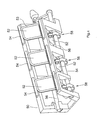
- the switching flaps 52 are not centered in this embodiment stored together with a shift shaft. Rather, the storage of the Switching flaps 52 separately via pivot axes 54, in the Einlegrahmen 50th are inserted.
- the in Fig. 4 on one side of the Einlegrahmens 50 side by side arranged switching flaps 52 can also have a common shaft 54th be stored.
- For pivoting the switching flaps 52 are two also in the Einlegrahmen 50 mounted shift shafts 56 is provided.
- the switching shafts 56 are about individual toggle mechanisms 58 with the individual switching flaps 52nd connected.
Landscapes
- Engineering & Computer Science (AREA)
- Chemical & Material Sciences (AREA)
- Combustion & Propulsion (AREA)
- Mechanical Engineering (AREA)
- General Engineering & Computer Science (AREA)
- Characterised By The Charging Evacuation (AREA)
- Multiple-Way Valves (AREA)
Abstract
Description
- Fig. 1
- eine schematische Schnittansicht eines Luftansaugkanalsystems mit einer ersten bevorzugten Ausführungsform der erfindungsgemäßen Schaltklappeneinrichtung,
- Fig.2
- eine schematische Draufsicht der in Fig. 1 dargestellten Schaltklappeneinrichtung,
- Fig. 3
- eine Schnittansicht entlang der Linie III-III in Fig. 2 und
- Fig. 4
- eine schematische perspektivische Ansicht einer zweiten bevorzugten Ausführungsform der Schaltklappeneinrichtung.
Claims (9)
- Schaltklappeneinrichtung zur Aufnahme mehrerer Schaltklappen (20, 52) für ein Luftansaugkanalsystem (10) einer Brennkraftmaschine, mit einer mit den Schaltklappen (20, 52) verbundenen Schaltwelle (24, 56) zum gemeinsamen Schalten der Schaltklappen (20)
dadurch gekennzeichnet, dass Schaltklappen (20, 52) und die Schaltwelle (24, 56) von einem Einlegrahmen (22, 50) getragen sind, der mit vormontierten Schaltklappen (20, 52) und vormontierter Schaltwelle (24, 56) in das Luftansaugsystem (10) einbaubar ist. - Schaltklappeneinrichtung nach Anspruch 1, dadurch gekennzeichnet, dass Wände (34, 36, 38) des Einlegrahmens (22, 50) zumindest teilweise einen Kurzschlusskanal (28) des Luftansaugkanalsystems (10) bilden.
- Schaltklappeneinrichtung nach Anspruch 2, dadurch gekennzeichnet, dass mindestens eine der den Kurzschlusskanal (28) bildenden Wände (34, 36, 38) eine Strömungskontur aufweist.
- Schaltklappeneinrichtung nach Anspruch 2 oder 3, dadurch gekennzeichnet, dass die Innenwand (34) konvex in Richtung des Strömungsverlaufs (30) gekrümmt ist.
- Schaltklappeneinrichtung nach einem der Ansprüche 1-4, dadurch gekennzeichnet, dass die Schaltwelle (24, 56) in dem Einlegrahmen (22, 50) gelagert ist.
- Schaltklappeneinrichtung nach einem der Ansprüche 1-5, dadurch gekennzeichnet, dass die Wände (34, 36, 38) und/oder die Schaltklappen (20, 52) mit einer Dichtung (32, 53) versehen sind.
- Schaltklappeneinrichtung nach Anspruch 6, dadurch gekennzeichnet, dass die Schaltklappen (20, 52) zum Halten der Dichtung (32, 53) Ausnehmungen aufweisen.
- Schaltklappeneinrichtung nach einem der Ansprüche 1-7, dadurch gekennzeichnet, dass die Schaltwelle (24) und die Schaltklappen (20) einstückig sind, so dass die Schaltklappen (20) mittels der Schaltwelle (24) in dem Einlegrahmen (22) gehalten sind.
- Schaltklappeneinrichtung nach einem der Ansprüche 1-7, dadurch gekennzeichnet, dass die Schaltklappen (52) unabhängig von der Schaltwelle (56) in dem Einlegrahmen (50) gelagert sind und die Schaltklappen (52) vorzugsweise über Kniehebelmechanismen (58) mit der Schaltwelle (56) verbunden sind.
Applications Claiming Priority (2)
| Application Number | Priority Date | Filing Date | Title |
|---|---|---|---|
| DE10143384 | 2001-09-05 | ||
| DE10143384A DE10143384C1 (de) | 2001-09-05 | 2001-09-05 | Schaltklappeneinrichtung |
Publications (3)
| Publication Number | Publication Date |
|---|---|
| EP1291504A2 true EP1291504A2 (de) | 2003-03-12 |
| EP1291504A3 EP1291504A3 (de) | 2004-06-09 |
| EP1291504B1 EP1291504B1 (de) | 2007-02-21 |
Family
ID=7697716
Family Applications (1)
| Application Number | Title | Priority Date | Filing Date |
|---|---|---|---|
| EP02018742A Expired - Lifetime EP1291504B1 (de) | 2001-09-05 | 2002-08-22 | Schaltklappeneinrichtung |
Country Status (3)
| Country | Link |
|---|---|
| EP (1) | EP1291504B1 (de) |
| DE (2) | DE10143384C1 (de) |
| ES (1) | ES2282351T3 (de) |
Cited By (5)
| Publication number | Priority date | Publication date | Assignee | Title |
|---|---|---|---|---|
| DE10348361A1 (de) * | 2003-10-17 | 2005-05-25 | Volkswagen Ag | Saugrohr für eine Brennkraftmaschine |
| KR100831581B1 (ko) | 2007-02-27 | 2008-05-22 | 주식회사 케피코 | 오프셋 플랩 밸브 타입 가변 흡기 장치 |
| DE102008055628A1 (de) * | 2008-11-03 | 2010-05-06 | Mann + Hummel Gmbh | Verfahren zur Herstellung eines Klappenverbandes |
| EP1764492A3 (de) * | 2005-09-20 | 2010-06-16 | Mahle International GmbH | Frischgasanlage für eine Brennkraftmaschine |
| DE102004005480B4 (de) * | 2004-02-04 | 2013-10-17 | GM Global Technology Operations LLC (n. d. Ges. d. Staates Delaware) | Schaltklappe für Saugrohr |
Families Citing this family (3)
| Publication number | Priority date | Publication date | Assignee | Title |
|---|---|---|---|---|
| DE10332640B3 (de) | 2003-07-18 | 2004-12-16 | Pierburg Gmbh | Luftansaugkanalsystem für Verbrennungskraftmaschinen |
| DE102004010555B4 (de) * | 2004-03-04 | 2006-02-09 | Pierburg Gmbh | Klappenlagerbefestigung |
| DE102009022862A1 (de) | 2009-05-27 | 2010-12-02 | Montaplast Gmbh | Luftansaugkanalsystem für Verbrennungskraftmaschinen mit einer Schalteinrichtung zur Längenschaltung |
Citations (1)
| Publication number | Priority date | Publication date | Assignee | Title |
|---|---|---|---|---|
| DE19614474A1 (de) | 1996-04-12 | 1997-10-16 | Pierburg Ag | Luftansaugkanalsystem für Brennkraftmaschinen |
Family Cites Families (6)
| Publication number | Priority date | Publication date | Assignee | Title |
|---|---|---|---|---|
| US5715782A (en) * | 1996-08-29 | 1998-02-10 | Genral Motors Corporation | Composite molded butterfly valve for an internal combustion engine |
| DE19651642A1 (de) * | 1996-12-12 | 1998-06-18 | Pierburg Ag | Lufteinlaßkanalsystem für Brennkraftmaschinen |
| US6135418A (en) * | 1999-02-10 | 2000-10-24 | Eaton Corporation | Low-leakage air valve for variable air intake system |
| DE19936470A1 (de) * | 1999-08-03 | 2001-02-08 | Mann & Hummel Filter | Saugrohranlage |
| DE19946861C2 (de) * | 1999-09-30 | 2001-07-26 | Audi Ag | Ansaugsystem einer Brennkraftmaschine |
| DE10119281A1 (de) * | 2001-04-20 | 2002-10-24 | Mann & Hummel Filter | Schaltverband zum Verschluss von Saugkanälen einer Ansaugvorrichtung mit diesem Schaltverband |
-
2001
- 2001-09-05 DE DE10143384A patent/DE10143384C1/de not_active Expired - Lifetime
-
2002
- 2002-08-22 DE DE50209524T patent/DE50209524D1/de not_active Expired - Fee Related
- 2002-08-22 ES ES02018742T patent/ES2282351T3/es not_active Expired - Lifetime
- 2002-08-22 EP EP02018742A patent/EP1291504B1/de not_active Expired - Lifetime
Patent Citations (1)
| Publication number | Priority date | Publication date | Assignee | Title |
|---|---|---|---|---|
| DE19614474A1 (de) | 1996-04-12 | 1997-10-16 | Pierburg Ag | Luftansaugkanalsystem für Brennkraftmaschinen |
Cited By (8)
| Publication number | Priority date | Publication date | Assignee | Title |
|---|---|---|---|---|
| DE10348361A1 (de) * | 2003-10-17 | 2005-05-25 | Volkswagen Ag | Saugrohr für eine Brennkraftmaschine |
| DE10348361B4 (de) * | 2003-10-17 | 2016-02-04 | Volkswagen Ag | Saugrohr für eine Brennkraftmaschine |
| DE102004005480B4 (de) * | 2004-02-04 | 2013-10-17 | GM Global Technology Operations LLC (n. d. Ges. d. Staates Delaware) | Schaltklappe für Saugrohr |
| EP1764492A3 (de) * | 2005-09-20 | 2010-06-16 | Mahle International GmbH | Frischgasanlage für eine Brennkraftmaschine |
| EP1764493A3 (de) * | 2005-09-20 | 2010-07-07 | Mahle International GmbH | Frischgasanlage für eine Brennkraftmaschine |
| EP1764492B2 (de) † | 2005-09-20 | 2016-01-27 | Mahle International GmbH | Frischgasanlage für eine Brennkraftmaschine |
| KR100831581B1 (ko) | 2007-02-27 | 2008-05-22 | 주식회사 케피코 | 오프셋 플랩 밸브 타입 가변 흡기 장치 |
| DE102008055628A1 (de) * | 2008-11-03 | 2010-05-06 | Mann + Hummel Gmbh | Verfahren zur Herstellung eines Klappenverbandes |
Also Published As
| Publication number | Publication date |
|---|---|
| EP1291504B1 (de) | 2007-02-21 |
| EP1291504A3 (de) | 2004-06-09 |
| ES2282351T3 (es) | 2007-10-16 |
| DE10143384C1 (de) | 2003-04-17 |
| DE50209524D1 (de) | 2007-04-05 |
Similar Documents
| Publication | Publication Date | Title |
|---|---|---|
| EP1251255B1 (de) | Ansaugvorrichtung | |
| EP0717815B1 (de) | Drosseleinrichtung | |
| WO2000065214A1 (de) | Schaltklappenverband aus montagegespritzten schaltklappen oder klappenmodulen | |
| EP1200718B1 (de) | Saugrohranlage | |
| EP1243774B1 (de) | Beheizbare Drosselvorrichtung für Brennkraftmaschinen | |
| EP1200721B1 (de) | Ventil | |
| DE19504382A1 (de) | Ansaugsystem | |
| DE19614474A1 (de) | Luftansaugkanalsystem für Brennkraftmaschinen | |
| DE102004056764A1 (de) | Drosselkörper und Verfahren zum Herstellen solcher Drosselkörper | |
| EP1291504A2 (de) | Schaltklappeneinrichtung | |
| EP0891486A1 (de) | Ansaugsystem für einen verbrennungsmotor | |
| DE10204768B4 (de) | Drallverstellbarer Einlasskanal mit zumindest einer in Längsrichtung verlaufenden Trennwand | |
| DE19717347C1 (de) | Verfahren zum Herstellen einer Schaltklappe | |
| EP1388652B1 (de) | Ansaugkanalsystem | |
| DE102013006196B4 (de) | Saugrohr für Gas einer Brennkraftmaschine mit einer Klappeneinheit | |
| DE19858626C1 (de) | Abgasklappenmechanismus für eine Brennkraftmaschine | |
| EP1251253A2 (de) | Schaltverband zum Verschluss von Saugkanälen einer Ansaugvorrichtung | |
| DE10346763A1 (de) | Saugmodul insbesondere für Brennkraftmaschinen | |
| EP1563174B1 (de) | Verfahren zur herstellung eines drosselklappenstutzens | |
| DE102004015330B4 (de) | Schaltklappeneinrichtung | |
| DE20221496U1 (de) | Ansaugkanalsystem | |
| DE10352781B3 (de) | Luftansaugkanalsystem für eine Verbrennungskraftmaschine | |
| DE112023005632T5 (de) | Doppelschnecken-turbine und turbolader | |
| EP1847701A2 (de) | Sauganlage für eine Brennkraftmaschine | |
| DE29913538U1 (de) | Saugrohranlage |
Legal Events
| Date | Code | Title | Description |
|---|---|---|---|
| PUAI | Public reference made under article 153(3) epc to a published international application that has entered the european phase |
Free format text: ORIGINAL CODE: 0009012 |
|
| AK | Designated contracting states |
Kind code of ref document: A2 Designated state(s): AT BE BG CH CY CZ DE DK EE ES FI FR GB GR IE IT LI LU MC NL PT SE SK TR |
|
| AX | Request for extension of the european patent |
Extension state: AL LT LV MK RO SI |
|
| RIN1 | Information on inventor provided before grant (corrected) |
Inventor name: SOVVA, ELINA Inventor name: CORBACH, PETER Inventor name: HUESGES, HANS-JUERGEN |
|
| PUAL | Search report despatched |
Free format text: ORIGINAL CODE: 0009013 |
|
| AK | Designated contracting states |
Kind code of ref document: A3 Designated state(s): AT BE BG CH CY CZ DE DK EE ES FI FR GB GR IE IT LI LU MC NL PT SE SK TR |
|
| AX | Request for extension of the european patent |
Extension state: AL LT LV MK RO SI |
|
| 17P | Request for examination filed |
Effective date: 20041123 |
|
| AKX | Designation fees paid |
Designated state(s): DE ES FR GB IT |
|
| 17Q | First examination report despatched |
Effective date: 20050224 |
|
| GRAP | Despatch of communication of intention to grant a patent |
Free format text: ORIGINAL CODE: EPIDOSNIGR1 |
|
| GRAS | Grant fee paid |
Free format text: ORIGINAL CODE: EPIDOSNIGR3 |
|
| GRAA | (expected) grant |
Free format text: ORIGINAL CODE: 0009210 |
|
| AK | Designated contracting states |
Kind code of ref document: B1 Designated state(s): DE ES FR GB IT |
|
| REG | Reference to a national code |
Ref country code: GB Ref legal event code: FG4D Free format text: NOT ENGLISH |
|
| REF | Corresponds to: |
Ref document number: 50209524 Country of ref document: DE Date of ref document: 20070405 Kind code of ref document: P |
|
| GBT | Gb: translation of ep patent filed (gb section 77(6)(a)/1977) |
Effective date: 20070523 |
|
| ET | Fr: translation filed | ||
| PGFP | Annual fee paid to national office [announced via postgrant information from national office to epo] |
Ref country code: DE Payment date: 20070822 Year of fee payment: 6 |
|
| REG | Reference to a national code |
Ref country code: ES Ref legal event code: FG2A Ref document number: 2282351 Country of ref document: ES Kind code of ref document: T3 |
|
| PLBE | No opposition filed within time limit |
Free format text: ORIGINAL CODE: 0009261 |
|
| STAA | Information on the status of an ep patent application or granted ep patent |
Free format text: STATUS: NO OPPOSITION FILED WITHIN TIME LIMIT |
|
| 26N | No opposition filed |
Effective date: 20071122 |
|
| PG25 | Lapsed in a contracting state [announced via postgrant information from national office to epo] |
Ref country code: DE Free format text: LAPSE BECAUSE OF NON-PAYMENT OF DUE FEES Effective date: 20090303 |
|
| PGFP | Annual fee paid to national office [announced via postgrant information from national office to epo] |
Ref country code: ES Payment date: 20100830 Year of fee payment: 9 |
|
| PGFP | Annual fee paid to national office [announced via postgrant information from national office to epo] |
Ref country code: FR Payment date: 20100901 Year of fee payment: 9 Ref country code: IT Payment date: 20100825 Year of fee payment: 9 |
|
| PGFP | Annual fee paid to national office [announced via postgrant information from national office to epo] |
Ref country code: GB Payment date: 20100823 Year of fee payment: 9 |
|
| GBPC | Gb: european patent ceased through non-payment of renewal fee |
Effective date: 20110822 |
|
| REG | Reference to a national code |
Ref country code: FR Ref legal event code: ST Effective date: 20120430 |
|
| PG25 | Lapsed in a contracting state [announced via postgrant information from national office to epo] |
Ref country code: IT Free format text: LAPSE BECAUSE OF NON-PAYMENT OF DUE FEES Effective date: 20110822 |
|
| PG25 | Lapsed in a contracting state [announced via postgrant information from national office to epo] |
Ref country code: GB Free format text: LAPSE BECAUSE OF NON-PAYMENT OF DUE FEES Effective date: 20110822 Ref country code: FR Free format text: LAPSE BECAUSE OF NON-PAYMENT OF DUE FEES Effective date: 20110831 |
|
| REG | Reference to a national code |
Ref country code: ES Ref legal event code: FD2A Effective date: 20131029 |
|
| PG25 | Lapsed in a contracting state [announced via postgrant information from national office to epo] |
Ref country code: ES Free format text: LAPSE BECAUSE OF NON-PAYMENT OF DUE FEES Effective date: 20110823 |