EP1291206A1 - Vorrichtung zur Thermalkontrolle, insbesondere für ein Kraftfahrzeug - Google Patents
Vorrichtung zur Thermalkontrolle, insbesondere für ein Kraftfahrzeug Download PDFInfo
- Publication number
- EP1291206A1 EP1291206A1 EP20020292192 EP02292192A EP1291206A1 EP 1291206 A1 EP1291206 A1 EP 1291206A1 EP 20020292192 EP20020292192 EP 20020292192 EP 02292192 A EP02292192 A EP 02292192A EP 1291206 A1 EP1291206 A1 EP 1291206A1
- Authority
- EP
- European Patent Office
- Prior art keywords
- branch
- exchanger
- thermal management
- circuit
- management device
- Prior art date
- Legal status (The legal status is an assumption and is not a legal conclusion. Google has not performed a legal analysis and makes no representation as to the accuracy of the status listed.)
- Granted
Links
Images


Classifications
-
- B—PERFORMING OPERATIONS; TRANSPORTING
- B60—VEHICLES IN GENERAL
- B60H—ARRANGEMENTS OF HEATING, COOLING, VENTILATING OR OTHER AIR-TREATING DEVICES SPECIALLY ADAPTED FOR PASSENGER OR GOODS SPACES OF VEHICLES
- B60H1/00—Heating, cooling or ventilating [HVAC] devices
- B60H1/00357—Air-conditioning arrangements specially adapted for particular vehicles
- B60H1/00385—Air-conditioning arrangements specially adapted for particular vehicles for vehicles having an electrical drive, e.g. hybrid or fuel cell
- B60H1/00392—Air-conditioning arrangements specially adapted for particular vehicles for vehicles having an electrical drive, e.g. hybrid or fuel cell for electric vehicles having only electric drive means
-
- B—PERFORMING OPERATIONS; TRANSPORTING
- B60—VEHICLES IN GENERAL
- B60H—ARRANGEMENTS OF HEATING, COOLING, VENTILATING OR OTHER AIR-TREATING DEVICES SPECIALLY ADAPTED FOR PASSENGER OR GOODS SPACES OF VEHICLES
- B60H1/00—Heating, cooling or ventilating [HVAC] devices
- B60H1/00007—Combined heating, ventilating, or cooling devices
-
- B—PERFORMING OPERATIONS; TRANSPORTING
- B60—VEHICLES IN GENERAL
- B60H—ARRANGEMENTS OF HEATING, COOLING, VENTILATING OR OTHER AIR-TREATING DEVICES SPECIALLY ADAPTED FOR PASSENGER OR GOODS SPACES OF VEHICLES
- B60H1/00—Heating, cooling or ventilating [HVAC] devices
- B60H1/00642—Control systems or circuits; Control members or indication devices for heating, cooling or ventilating devices
- B60H1/00814—Control systems or circuits characterised by their output, for controlling particular components of the heating, cooling or ventilating installation
- B60H1/00878—Control systems or circuits characterised by their output, for controlling particular components of the heating, cooling or ventilating installation the components being temperature regulating devices
- B60H1/00885—Controlling the flow of heating or cooling liquid, e.g. valves or pumps
-
- B—PERFORMING OPERATIONS; TRANSPORTING
- B60—VEHICLES IN GENERAL
- B60H—ARRANGEMENTS OF HEATING, COOLING, VENTILATING OR OTHER AIR-TREATING DEVICES SPECIALLY ADAPTED FOR PASSENGER OR GOODS SPACES OF VEHICLES
- B60H1/00—Heating, cooling or ventilating [HVAC] devices
- B60H1/32—Cooling devices
- B60H1/3204—Cooling devices using compression
- B60H1/3228—Cooling devices using compression characterised by refrigerant circuit configurations
- B60H1/32284—Cooling devices using compression characterised by refrigerant circuit configurations comprising two or more secondary circuits, e.g. at evaporator and condenser side
-
- B—PERFORMING OPERATIONS; TRANSPORTING
- B60—VEHICLES IN GENERAL
- B60L—PROPULSION OF ELECTRICALLY-PROPELLED VEHICLES; SUPPLYING ELECTRIC POWER FOR AUXILIARY EQUIPMENT OF ELECTRICALLY-PROPELLED VEHICLES; ELECTRODYNAMIC BRAKE SYSTEMS FOR VEHICLES IN GENERAL; MAGNETIC SUSPENSION OR LEVITATION FOR VEHICLES; MONITORING OPERATING VARIABLES OF ELECTRICALLY-PROPELLED VEHICLES; ELECTRIC SAFETY DEVICES FOR ELECTRICALLY-PROPELLED VEHICLES
- B60L1/00—Supplying electric power to auxiliary equipment of vehicles
- B60L1/003—Supplying electric power to auxiliary equipment of vehicles to auxiliary motors, e.g. for pumps, compressors
-
- B—PERFORMING OPERATIONS; TRANSPORTING
- B60—VEHICLES IN GENERAL
- B60L—PROPULSION OF ELECTRICALLY-PROPELLED VEHICLES; SUPPLYING ELECTRIC POWER FOR AUXILIARY EQUIPMENT OF ELECTRICALLY-PROPELLED VEHICLES; ELECTRODYNAMIC BRAKE SYSTEMS FOR VEHICLES IN GENERAL; MAGNETIC SUSPENSION OR LEVITATION FOR VEHICLES; MONITORING OPERATING VARIABLES OF ELECTRICALLY-PROPELLED VEHICLES; ELECTRIC SAFETY DEVICES FOR ELECTRICALLY-PROPELLED VEHICLES
- B60L1/00—Supplying electric power to auxiliary equipment of vehicles
- B60L1/02—Supplying electric power to auxiliary equipment of vehicles to electric heating circuits
-
- B—PERFORMING OPERATIONS; TRANSPORTING
- B60—VEHICLES IN GENERAL
- B60L—PROPULSION OF ELECTRICALLY-PROPELLED VEHICLES; SUPPLYING ELECTRIC POWER FOR AUXILIARY EQUIPMENT OF ELECTRICALLY-PROPELLED VEHICLES; ELECTRODYNAMIC BRAKE SYSTEMS FOR VEHICLES IN GENERAL; MAGNETIC SUSPENSION OR LEVITATION FOR VEHICLES; MONITORING OPERATING VARIABLES OF ELECTRICALLY-PROPELLED VEHICLES; ELECTRIC SAFETY DEVICES FOR ELECTRICALLY-PROPELLED VEHICLES
- B60L3/00—Electric devices on electrically-propelled vehicles for safety purposes; Monitoring operating variables, e.g. speed, deceleration or energy consumption
- B60L3/0023—Detecting, eliminating, remedying or compensating for drive train abnormalities, e.g. failures within the drive train
- B60L3/003—Detecting, eliminating, remedying or compensating for drive train abnormalities, e.g. failures within the drive train relating to inverters
-
- B—PERFORMING OPERATIONS; TRANSPORTING
- B60—VEHICLES IN GENERAL
- B60L—PROPULSION OF ELECTRICALLY-PROPELLED VEHICLES; SUPPLYING ELECTRIC POWER FOR AUXILIARY EQUIPMENT OF ELECTRICALLY-PROPELLED VEHICLES; ELECTRODYNAMIC BRAKE SYSTEMS FOR VEHICLES IN GENERAL; MAGNETIC SUSPENSION OR LEVITATION FOR VEHICLES; MONITORING OPERATING VARIABLES OF ELECTRICALLY-PROPELLED VEHICLES; ELECTRIC SAFETY DEVICES FOR ELECTRICALLY-PROPELLED VEHICLES
- B60L3/00—Electric devices on electrically-propelled vehicles for safety purposes; Monitoring operating variables, e.g. speed, deceleration or energy consumption
- B60L3/0023—Detecting, eliminating, remedying or compensating for drive train abnormalities, e.g. failures within the drive train
- B60L3/0061—Detecting, eliminating, remedying or compensating for drive train abnormalities, e.g. failures within the drive train relating to electrical machines
-
- B—PERFORMING OPERATIONS; TRANSPORTING
- B60—VEHICLES IN GENERAL
- B60L—PROPULSION OF ELECTRICALLY-PROPELLED VEHICLES; SUPPLYING ELECTRIC POWER FOR AUXILIARY EQUIPMENT OF ELECTRICALLY-PROPELLED VEHICLES; ELECTRODYNAMIC BRAKE SYSTEMS FOR VEHICLES IN GENERAL; MAGNETIC SUSPENSION OR LEVITATION FOR VEHICLES; MONITORING OPERATING VARIABLES OF ELECTRICALLY-PROPELLED VEHICLES; ELECTRIC SAFETY DEVICES FOR ELECTRICALLY-PROPELLED VEHICLES
- B60L58/00—Methods or circuit arrangements for monitoring or controlling batteries or fuel cells, specially adapted for electric vehicles
- B60L58/10—Methods or circuit arrangements for monitoring or controlling batteries or fuel cells, specially adapted for electric vehicles for monitoring or controlling batteries
- B60L58/24—Methods or circuit arrangements for monitoring or controlling batteries or fuel cells, specially adapted for electric vehicles for monitoring or controlling batteries for controlling the temperature of batteries
- B60L58/26—Methods or circuit arrangements for monitoring or controlling batteries or fuel cells, specially adapted for electric vehicles for monitoring or controlling batteries for controlling the temperature of batteries by cooling
-
- B—PERFORMING OPERATIONS; TRANSPORTING
- B60—VEHICLES IN GENERAL
- B60L—PROPULSION OF ELECTRICALLY-PROPELLED VEHICLES; SUPPLYING ELECTRIC POWER FOR AUXILIARY EQUIPMENT OF ELECTRICALLY-PROPELLED VEHICLES; ELECTRODYNAMIC BRAKE SYSTEMS FOR VEHICLES IN GENERAL; MAGNETIC SUSPENSION OR LEVITATION FOR VEHICLES; MONITORING OPERATING VARIABLES OF ELECTRICALLY-PROPELLED VEHICLES; ELECTRIC SAFETY DEVICES FOR ELECTRICALLY-PROPELLED VEHICLES
- B60L58/00—Methods or circuit arrangements for monitoring or controlling batteries or fuel cells, specially adapted for electric vehicles
- B60L58/10—Methods or circuit arrangements for monitoring or controlling batteries or fuel cells, specially adapted for electric vehicles for monitoring or controlling batteries
- B60L58/24—Methods or circuit arrangements for monitoring or controlling batteries or fuel cells, specially adapted for electric vehicles for monitoring or controlling batteries for controlling the temperature of batteries
- B60L58/27—Methods or circuit arrangements for monitoring or controlling batteries or fuel cells, specially adapted for electric vehicles for monitoring or controlling batteries for controlling the temperature of batteries by heating
-
- B—PERFORMING OPERATIONS; TRANSPORTING
- B60—VEHICLES IN GENERAL
- B60L—PROPULSION OF ELECTRICALLY-PROPELLED VEHICLES; SUPPLYING ELECTRIC POWER FOR AUXILIARY EQUIPMENT OF ELECTRICALLY-PROPELLED VEHICLES; ELECTRODYNAMIC BRAKE SYSTEMS FOR VEHICLES IN GENERAL; MAGNETIC SUSPENSION OR LEVITATION FOR VEHICLES; MONITORING OPERATING VARIABLES OF ELECTRICALLY-PROPELLED VEHICLES; ELECTRIC SAFETY DEVICES FOR ELECTRICALLY-PROPELLED VEHICLES
- B60L58/00—Methods or circuit arrangements for monitoring or controlling batteries or fuel cells, specially adapted for electric vehicles
- B60L58/30—Methods or circuit arrangements for monitoring or controlling batteries or fuel cells, specially adapted for electric vehicles for monitoring or controlling fuel cells
- B60L58/32—Methods or circuit arrangements for monitoring or controlling batteries or fuel cells, specially adapted for electric vehicles for monitoring or controlling fuel cells for controlling the temperature of fuel cells, e.g. by controlling the electric load
- B60L58/33—Methods or circuit arrangements for monitoring or controlling batteries or fuel cells, specially adapted for electric vehicles for monitoring or controlling fuel cells for controlling the temperature of fuel cells, e.g. by controlling the electric load by cooling
-
- B—PERFORMING OPERATIONS; TRANSPORTING
- B60—VEHICLES IN GENERAL
- B60L—PROPULSION OF ELECTRICALLY-PROPELLED VEHICLES; SUPPLYING ELECTRIC POWER FOR AUXILIARY EQUIPMENT OF ELECTRICALLY-PROPELLED VEHICLES; ELECTRODYNAMIC BRAKE SYSTEMS FOR VEHICLES IN GENERAL; MAGNETIC SUSPENSION OR LEVITATION FOR VEHICLES; MONITORING OPERATING VARIABLES OF ELECTRICALLY-PROPELLED VEHICLES; ELECTRIC SAFETY DEVICES FOR ELECTRICALLY-PROPELLED VEHICLES
- B60L58/00—Methods or circuit arrangements for monitoring or controlling batteries or fuel cells, specially adapted for electric vehicles
- B60L58/30—Methods or circuit arrangements for monitoring or controlling batteries or fuel cells, specially adapted for electric vehicles for monitoring or controlling fuel cells
- B60L58/32—Methods or circuit arrangements for monitoring or controlling batteries or fuel cells, specially adapted for electric vehicles for monitoring or controlling fuel cells for controlling the temperature of fuel cells, e.g. by controlling the electric load
- B60L58/34—Methods or circuit arrangements for monitoring or controlling batteries or fuel cells, specially adapted for electric vehicles for monitoring or controlling fuel cells for controlling the temperature of fuel cells, e.g. by controlling the electric load by heating
-
- B—PERFORMING OPERATIONS; TRANSPORTING
- B60—VEHICLES IN GENERAL
- B60L—PROPULSION OF ELECTRICALLY-PROPELLED VEHICLES; SUPPLYING ELECTRIC POWER FOR AUXILIARY EQUIPMENT OF ELECTRICALLY-PROPELLED VEHICLES; ELECTRODYNAMIC BRAKE SYSTEMS FOR VEHICLES IN GENERAL; MAGNETIC SUSPENSION OR LEVITATION FOR VEHICLES; MONITORING OPERATING VARIABLES OF ELECTRICALLY-PROPELLED VEHICLES; ELECTRIC SAFETY DEVICES FOR ELECTRICALLY-PROPELLED VEHICLES
- B60L58/00—Methods or circuit arrangements for monitoring or controlling batteries or fuel cells, specially adapted for electric vehicles
- B60L58/40—Methods or circuit arrangements for monitoring or controlling batteries or fuel cells, specially adapted for electric vehicles for controlling a combination of batteries and fuel cells
-
- F—MECHANICAL ENGINEERING; LIGHTING; HEATING; WEAPONS; BLASTING
- F01—MACHINES OR ENGINES IN GENERAL; ENGINE PLANTS IN GENERAL; STEAM ENGINES
- F01P—COOLING OF MACHINES OR ENGINES IN GENERAL; COOLING OF INTERNAL-COMBUSTION ENGINES
- F01P3/00—Liquid cooling
- F01P3/20—Cooling circuits not specific to a single part of engine or machine
-
- H—ELECTRICITY
- H01—ELECTRIC ELEMENTS
- H01M—PROCESSES OR MEANS, e.g. BATTERIES, FOR THE DIRECT CONVERSION OF CHEMICAL ENERGY INTO ELECTRICAL ENERGY
- H01M10/00—Secondary cells; Manufacture thereof
- H01M10/60—Heating or cooling; Temperature control
- H01M10/61—Types of temperature control
- H01M10/613—Cooling or keeping cold
-
- H—ELECTRICITY
- H01—ELECTRIC ELEMENTS
- H01M—PROCESSES OR MEANS, e.g. BATTERIES, FOR THE DIRECT CONVERSION OF CHEMICAL ENERGY INTO ELECTRICAL ENERGY
- H01M10/00—Secondary cells; Manufacture thereof
- H01M10/60—Heating or cooling; Temperature control
- H01M10/62—Heating or cooling; Temperature control specially adapted for specific applications
- H01M10/625—Vehicles
-
- H—ELECTRICITY
- H01—ELECTRIC ELEMENTS
- H01M—PROCESSES OR MEANS, e.g. BATTERIES, FOR THE DIRECT CONVERSION OF CHEMICAL ENERGY INTO ELECTRICAL ENERGY
- H01M10/00—Secondary cells; Manufacture thereof
- H01M10/60—Heating or cooling; Temperature control
- H01M10/66—Heat-exchange relationships between the cells and other systems, e.g. central heating systems or fuel cells
- H01M10/663—Heat-exchange relationships between the cells and other systems, e.g. central heating systems or fuel cells the system being an air-conditioner or an engine
-
- H—ELECTRICITY
- H01—ELECTRIC ELEMENTS
- H01M—PROCESSES OR MEANS, e.g. BATTERIES, FOR THE DIRECT CONVERSION OF CHEMICAL ENERGY INTO ELECTRICAL ENERGY
- H01M16/00—Structural combinations of different types of electrochemical generators
- H01M16/003—Structural combinations of different types of electrochemical generators of fuel cells with other electrochemical devices, e.g. capacitors, electrolysers
- H01M16/006—Structural combinations of different types of electrochemical generators of fuel cells with other electrochemical devices, e.g. capacitors, electrolysers of fuel cells with rechargeable batteries
-
- H—ELECTRICITY
- H01—ELECTRIC ELEMENTS
- H01M—PROCESSES OR MEANS, e.g. BATTERIES, FOR THE DIRECT CONVERSION OF CHEMICAL ENERGY INTO ELECTRICAL ENERGY
- H01M6/00—Primary cells; Manufacture thereof
- H01M6/50—Methods or arrangements for servicing or maintenance, e.g. for maintaining operating temperature
- H01M6/5038—Heating or cooling of cells or batteries
-
- H—ELECTRICITY
- H01—ELECTRIC ELEMENTS
- H01M—PROCESSES OR MEANS, e.g. BATTERIES, FOR THE DIRECT CONVERSION OF CHEMICAL ENERGY INTO ELECTRICAL ENERGY
- H01M8/00—Fuel cells; Manufacture thereof
- H01M8/04—Auxiliary arrangements, e.g. for control of pressure or for circulation of fluids
- H01M8/04007—Auxiliary arrangements, e.g. for control of pressure or for circulation of fluids related to heat exchange
- H01M8/04029—Heat exchange using liquids
-
- H—ELECTRICITY
- H01—ELECTRIC ELEMENTS
- H01M—PROCESSES OR MEANS, e.g. BATTERIES, FOR THE DIRECT CONVERSION OF CHEMICAL ENERGY INTO ELECTRICAL ENERGY
- H01M8/00—Fuel cells; Manufacture thereof
- H01M8/04—Auxiliary arrangements, e.g. for control of pressure or for circulation of fluids
- H01M8/04082—Arrangements for control of reactant parameters, e.g. pressure or concentration
- H01M8/04089—Arrangements for control of reactant parameters, e.g. pressure or concentration of gaseous reactants
- H01M8/04119—Arrangements for control of reactant parameters, e.g. pressure or concentration of gaseous reactants with simultaneous supply or evacuation of electrolyte; Humidifying or dehumidifying
- H01M8/04156—Arrangements for control of reactant parameters, e.g. pressure or concentration of gaseous reactants with simultaneous supply or evacuation of electrolyte; Humidifying or dehumidifying with product water removal
- H01M8/04164—Arrangements for control of reactant parameters, e.g. pressure or concentration of gaseous reactants with simultaneous supply or evacuation of electrolyte; Humidifying or dehumidifying with product water removal by condensers, gas-liquid separators or filters
-
- B—PERFORMING OPERATIONS; TRANSPORTING
- B60—VEHICLES IN GENERAL
- B60H—ARRANGEMENTS OF HEATING, COOLING, VENTILATING OR OTHER AIR-TREATING DEVICES SPECIALLY ADAPTED FOR PASSENGER OR GOODS SPACES OF VEHICLES
- B60H1/00—Heating, cooling or ventilating [HVAC] devices
- B60H1/00642—Control systems or circuits; Control members or indication devices for heating, cooling or ventilating devices
- B60H1/00814—Control systems or circuits characterised by their output, for controlling particular components of the heating, cooling or ventilating installation
- B60H1/00878—Control systems or circuits characterised by their output, for controlling particular components of the heating, cooling or ventilating installation the components being temperature regulating devices
- B60H2001/00928—Control systems or circuits characterised by their output, for controlling particular components of the heating, cooling or ventilating installation the components being temperature regulating devices comprising a secondary circuit
-
- B—PERFORMING OPERATIONS; TRANSPORTING
- B60—VEHICLES IN GENERAL
- B60L—PROPULSION OF ELECTRICALLY-PROPELLED VEHICLES; SUPPLYING ELECTRIC POWER FOR AUXILIARY EQUIPMENT OF ELECTRICALLY-PROPELLED VEHICLES; ELECTRODYNAMIC BRAKE SYSTEMS FOR VEHICLES IN GENERAL; MAGNETIC SUSPENSION OR LEVITATION FOR VEHICLES; MONITORING OPERATING VARIABLES OF ELECTRICALLY-PROPELLED VEHICLES; ELECTRIC SAFETY DEVICES FOR ELECTRICALLY-PROPELLED VEHICLES
- B60L2200/00—Type of vehicles
- B60L2200/26—Rail vehicles
-
- B—PERFORMING OPERATIONS; TRANSPORTING
- B60—VEHICLES IN GENERAL
- B60L—PROPULSION OF ELECTRICALLY-PROPELLED VEHICLES; SUPPLYING ELECTRIC POWER FOR AUXILIARY EQUIPMENT OF ELECTRICALLY-PROPELLED VEHICLES; ELECTRODYNAMIC BRAKE SYSTEMS FOR VEHICLES IN GENERAL; MAGNETIC SUSPENSION OR LEVITATION FOR VEHICLES; MONITORING OPERATING VARIABLES OF ELECTRICALLY-PROPELLED VEHICLES; ELECTRIC SAFETY DEVICES FOR ELECTRICALLY-PROPELLED VEHICLES
- B60L2210/00—Converter types
- B60L2210/10—DC to DC converters
-
- B—PERFORMING OPERATIONS; TRANSPORTING
- B60—VEHICLES IN GENERAL
- B60L—PROPULSION OF ELECTRICALLY-PROPELLED VEHICLES; SUPPLYING ELECTRIC POWER FOR AUXILIARY EQUIPMENT OF ELECTRICALLY-PROPELLED VEHICLES; ELECTRODYNAMIC BRAKE SYSTEMS FOR VEHICLES IN GENERAL; MAGNETIC SUSPENSION OR LEVITATION FOR VEHICLES; MONITORING OPERATING VARIABLES OF ELECTRICALLY-PROPELLED VEHICLES; ELECTRIC SAFETY DEVICES FOR ELECTRICALLY-PROPELLED VEHICLES
- B60L2240/00—Control parameters of input or output; Target parameters
- B60L2240/10—Vehicle control parameters
- B60L2240/34—Cabin temperature
-
- B—PERFORMING OPERATIONS; TRANSPORTING
- B60—VEHICLES IN GENERAL
- B60L—PROPULSION OF ELECTRICALLY-PROPELLED VEHICLES; SUPPLYING ELECTRIC POWER FOR AUXILIARY EQUIPMENT OF ELECTRICALLY-PROPELLED VEHICLES; ELECTRODYNAMIC BRAKE SYSTEMS FOR VEHICLES IN GENERAL; MAGNETIC SUSPENSION OR LEVITATION FOR VEHICLES; MONITORING OPERATING VARIABLES OF ELECTRICALLY-PROPELLED VEHICLES; ELECTRIC SAFETY DEVICES FOR ELECTRICALLY-PROPELLED VEHICLES
- B60L2240/00—Control parameters of input or output; Target parameters
- B60L2240/10—Vehicle control parameters
- B60L2240/36—Temperature of vehicle components or parts
-
- F—MECHANICAL ENGINEERING; LIGHTING; HEATING; WEAPONS; BLASTING
- F01—MACHINES OR ENGINES IN GENERAL; ENGINE PLANTS IN GENERAL; STEAM ENGINES
- F01P—COOLING OF MACHINES OR ENGINES IN GENERAL; COOLING OF INTERNAL-COMBUSTION ENGINES
- F01P7/00—Controlling of coolant flow
- F01P7/14—Controlling of coolant flow the coolant being liquid
- F01P2007/146—Controlling of coolant flow the coolant being liquid using valves
-
- F—MECHANICAL ENGINEERING; LIGHTING; HEATING; WEAPONS; BLASTING
- F01—MACHINES OR ENGINES IN GENERAL; ENGINE PLANTS IN GENERAL; STEAM ENGINES
- F01P—COOLING OF MACHINES OR ENGINES IN GENERAL; COOLING OF INTERNAL-COMBUSTION ENGINES
- F01P2060/00—Cooling circuits using auxiliaries
- F01P2060/14—Condenser
-
- F—MECHANICAL ENGINEERING; LIGHTING; HEATING; WEAPONS; BLASTING
- F01—MACHINES OR ENGINES IN GENERAL; ENGINE PLANTS IN GENERAL; STEAM ENGINES
- F01P—COOLING OF MACHINES OR ENGINES IN GENERAL; COOLING OF INTERNAL-COMBUSTION ENGINES
- F01P9/00—Cooling having pertinent characteristics not provided for in, or of interest apart from, groups F01P1/00 - F01P7/00
- F01P9/06—Cooling having pertinent characteristics not provided for in, or of interest apart from, groups F01P1/00 - F01P7/00 by use of refrigerating apparatus, e.g. of compressor or absorber type
-
- H—ELECTRICITY
- H01—ELECTRIC ELEMENTS
- H01M—PROCESSES OR MEANS, e.g. BATTERIES, FOR THE DIRECT CONVERSION OF CHEMICAL ENERGY INTO ELECTRICAL ENERGY
- H01M10/00—Secondary cells; Manufacture thereof
- H01M10/60—Heating or cooling; Temperature control
- H01M10/65—Means for temperature control structurally associated with the cells
- H01M10/656—Means for temperature control structurally associated with the cells characterised by the type of heat-exchange fluid
- H01M10/6561—Gases
-
- Y—GENERAL TAGGING OF NEW TECHNOLOGICAL DEVELOPMENTS; GENERAL TAGGING OF CROSS-SECTIONAL TECHNOLOGIES SPANNING OVER SEVERAL SECTIONS OF THE IPC; TECHNICAL SUBJECTS COVERED BY FORMER USPC CROSS-REFERENCE ART COLLECTIONS [XRACs] AND DIGESTS
- Y02—TECHNOLOGIES OR APPLICATIONS FOR MITIGATION OR ADAPTATION AGAINST CLIMATE CHANGE
- Y02E—REDUCTION OF GREENHOUSE GAS [GHG] EMISSIONS, RELATED TO ENERGY GENERATION, TRANSMISSION OR DISTRIBUTION
- Y02E60/00—Enabling technologies; Technologies with a potential or indirect contribution to GHG emissions mitigation
- Y02E60/10—Energy storage using batteries
-
- Y—GENERAL TAGGING OF NEW TECHNOLOGICAL DEVELOPMENTS; GENERAL TAGGING OF CROSS-SECTIONAL TECHNOLOGIES SPANNING OVER SEVERAL SECTIONS OF THE IPC; TECHNICAL SUBJECTS COVERED BY FORMER USPC CROSS-REFERENCE ART COLLECTIONS [XRACs] AND DIGESTS
- Y02—TECHNOLOGIES OR APPLICATIONS FOR MITIGATION OR ADAPTATION AGAINST CLIMATE CHANGE
- Y02E—REDUCTION OF GREENHOUSE GAS [GHG] EMISSIONS, RELATED TO ENERGY GENERATION, TRANSMISSION OR DISTRIBUTION
- Y02E60/00—Enabling technologies; Technologies with a potential or indirect contribution to GHG emissions mitigation
- Y02E60/30—Hydrogen technology
- Y02E60/50—Fuel cells
-
- Y—GENERAL TAGGING OF NEW TECHNOLOGICAL DEVELOPMENTS; GENERAL TAGGING OF CROSS-SECTIONAL TECHNOLOGIES SPANNING OVER SEVERAL SECTIONS OF THE IPC; TECHNICAL SUBJECTS COVERED BY FORMER USPC CROSS-REFERENCE ART COLLECTIONS [XRACs] AND DIGESTS
- Y02—TECHNOLOGIES OR APPLICATIONS FOR MITIGATION OR ADAPTATION AGAINST CLIMATE CHANGE
- Y02T—CLIMATE CHANGE MITIGATION TECHNOLOGIES RELATED TO TRANSPORTATION
- Y02T10/00—Road transport of goods or passengers
- Y02T10/60—Other road transportation technologies with climate change mitigation effect
- Y02T10/70—Energy storage systems for electromobility, e.g. batteries
-
- Y—GENERAL TAGGING OF NEW TECHNOLOGICAL DEVELOPMENTS; GENERAL TAGGING OF CROSS-SECTIONAL TECHNOLOGIES SPANNING OVER SEVERAL SECTIONS OF THE IPC; TECHNICAL SUBJECTS COVERED BY FORMER USPC CROSS-REFERENCE ART COLLECTIONS [XRACs] AND DIGESTS
- Y02—TECHNOLOGIES OR APPLICATIONS FOR MITIGATION OR ADAPTATION AGAINST CLIMATE CHANGE
- Y02T—CLIMATE CHANGE MITIGATION TECHNOLOGIES RELATED TO TRANSPORTATION
- Y02T10/00—Road transport of goods or passengers
- Y02T10/60—Other road transportation technologies with climate change mitigation effect
- Y02T10/72—Electric energy management in electromobility
-
- Y—GENERAL TAGGING OF NEW TECHNOLOGICAL DEVELOPMENTS; GENERAL TAGGING OF CROSS-SECTIONAL TECHNOLOGIES SPANNING OVER SEVERAL SECTIONS OF THE IPC; TECHNICAL SUBJECTS COVERED BY FORMER USPC CROSS-REFERENCE ART COLLECTIONS [XRACs] AND DIGESTS
- Y02—TECHNOLOGIES OR APPLICATIONS FOR MITIGATION OR ADAPTATION AGAINST CLIMATE CHANGE
- Y02T—CLIMATE CHANGE MITIGATION TECHNOLOGIES RELATED TO TRANSPORTATION
- Y02T90/00—Enabling technologies or technologies with a potential or indirect contribution to GHG emissions mitigation
- Y02T90/40—Application of hydrogen technology to transportation, e.g. using fuel cells
Definitions
- the invention relates to a device for thermal management of at least one first heat exchanger, in particular for a motor vehicle, comprising a primary refrigerant circuit in which a fluid is caused to circulate refrigerant and into which are inserted in series at least one compressor, one condenser, a pressure reducer and an evaporator, a secondary circuit in which is caused to circulate a heat transfer fluid and in which are inserted at least said first heat exchanger, and said condenser or said evaporator, said circuit secondary comprising means for circulating said heat transfer fluid.
- the refrigerant circuit of this device is arranged so that, selectively according to the setting of the flow regulation means and the direction of circulation of the refrigerant through an exchanger, the refrigerant condenses or evaporates therein producing heat energy or refrigeration, respectively.
- the heat or cooling energy thus produced can then, for example, be transported, via a heat transfer fluid circulating in a second circuit, to a vehicle member inserted in this second circuit and to be heated or cooled, respectively.
- the refrigerant circuit includes as many heat exchangers and regulators that there are organs to manage. A large volume of refrigerant is therefore necessary. However, the refrigerant is very expensive. In addition, it is little ecological and the many pipes connecting the different circuit components increase the risk of leakage and rejection in the environment.
- the object of the present invention is to provide a management device thermal only requiring a limited volume of refrigerant.
- a thermal management device of at least a first heat exchanger in particular for a motor vehicle, comprising a primary refrigerant circuit in which a fluid is caused to circulate refrigerant and into which are inserted in series at least one compressor, one condenser, a pressure reducer and an evaporator, a secondary circuit in which is caused to circulate a heat transfer fluid and in which are inserted at least said first heat exchanger, and said condenser or said evaporator, said circuit secondary comprising means for circulating said heat transfer fluid, remarkable in that said secondary circuit includes first, second and third parallel branches in which said first are inserted exchanger, said condenser and said evaporator, respectively, said circuit secondary further comprising means for selective connection of said first branch with said second branch or said third branch, of so as to be able to selectively heat in said condenser or cool in said evaporator the heat transfer fluid intended to pass through said first exchanger.
- the thermal regulation of the exchanger and in particular the selection of the production of heat energy or cooling energy in this exchanger, is therefore carried out, as will be seen in more detail below, by action on the selective connection means.
- the refrigerant circuit can thus comprise only one compressor, condenser, expansion valve and evaporator inserted in series in a short loop. The volume of refrigerant is thus reduced to a minimum quantity.
- the heat or cooling energy intended for said first exchanger is transported by said heat transfer fluid, for example glycol water, the cost of which is weak and whose implementation is not very restrictive.
- said heat transfer fluid for example glycol water, the cost of which is weak and whose implementation is not very restrictive.
- the heat transfer fluid relatively ecological compared to the refrigerant, can indeed be implemented circulation under low pressure.
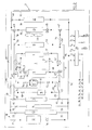
- the device shown in Figures 1 to 4 includes a primary circuit or refrigerant circuit 1, in which a refrigerant is circulated and in which are inserted in series at least one compressor 3, a condenser 5, a regulator 7 and an evaporator 9.
- the condenser 5 and the evaporator 9 are also inserted in a circuit secondary 10 in which a heat transfer fluid is circulated, for example distilled water.
- each exchanger-member couple defining a functional unit.
- the heat transfer fluid When the heat transfer fluid is compatible with an organ, it can be contact with it, the exchanger and the member then being combined. On the contrary, if there is incompatibility, the heat exchange relationship between an organ and an exchanger can be carried out by means of a heat transfer fluid such as for example air or oil.
- the vehicle engine is a fuel cell type.
- the invention can be implemented in a vehicle fitted with a conventional internal combustion engine.
- the secondary circuit 10 includes ten exchangers 12 to 21.
- the exchanger 13 is selectively in heat exchange relationship with an air dehumidifier so as to regenerate, i.e. evaporate the water it has condensed, for example by dehumidifying the air intended to be cooled by the air conditioning device of the passenger compartment of the vehicle V.
- the exchanger 13 is associated with a valve 23.
- Exchangers 14 and 16 also being called “Air heater”, are in heat exchange relationship with the passenger compartment of the vehicle V.
- the exchanger 14 is a heat-exchange fluid-air exchanger arranged so as to the air extracted from the passenger compartment passes through it.
- the exchanger 15 also called an air heater, can be selectively in heat exchange relationship with the passenger compartment of vehicle V or with the outside, as will be seen in more detail in the following description ( Figure 5).
- Exchangers 17 and 18, mounted parallel to each other, are in heat exchange relationship with one or more batteries and with a group of electronic components, respectively.
- the exchanger 19, or "water condenser” is intended to condense the vapor of water at the outlet of the fuel cell so that it can be reused.
- exchangers 20 and 21, or “first and second radiators”, respectively, are in heat exchange relationship with the outside air.
- the exchangers 20 and 21 are associated with a fan 28.
- the secondary circuit 10 consists of three elementary circuits connected together.
- the first elementary circuit has seven parallel branches 31 to 37.
- the six branches 31 to 36 are inserted respectively the battery exchanger 12 and a pump 38, the dehumidifier regenerator 13 and the valve 23, the exchanger 14 and a valve 39, the air heater 15 associated on one side with a valve three-way 40, on the other to a three-way valve 41, the first radiator 20 associated on one side with a three-way valve 43, on the other with a circulation 45 and a three-way valve 47, and the second radiator 21, associated to a three-way valve 48.
- the seventh branch 37 is a branch of derivation from the second radiator 21. It is connected to the three-way valve 48.
- the branches 31 to 37 are connected together by first and second joint branches, 49 and 50 respectively, joint branch 49 being connected to the three-way valve 48.
- the second elementary circuit has two parallel branches 51 and 53 connected to each other by means of first and second valves to four channels, 55 and 57 respectively, and into which the condenser 5 and water condenser 19, respectively.
- the third elementary circuit has two parallel branches 60 and 63 connected together via the two four-way valves 55 and 57.
- a gate valve three-way 64 and a cold storage system 65 for example a balloon for storing frigories brought by the coolant cooled during of the bushing of the evaporator 9.
- the valve 64 is also connected to a branch branch 66 of the cold storage system 65, so as to serve of means for regulating the flow of the heat-transfer fluid in the storage system 65 and in branch branch 66.
- branch 63 are successively inserted a pump 67, the heater 16 and two valves 68 and 69.
- the third elementary circuit also includes a third branch 70 in which are inserted in series a valve 72, the assembly formed by the exchangers 17 and 18 and a valve 74.
- the branch 70 is connected on the one hand to the branch 60 at a point 76 located between the storage system 65 and the gate valve four lanes 55, and secondly to branch 63 at a point 77 located between the pump 67 and the heater 16.
- connection branch 78 is connected on the one hand at a point 80 of the branch 53 located between the water condenser 19 and the four-way valve 55 and on the other hand to the three-way valve 43.
- connection branch 79 is connected on the one hand at a point 80 'of the branch 53 located between the water condenser 19 and the four-way valve 57, and on the other hand to the three-way valve 47.
- connection branches 81 and 83 The first and third elementary circuits are connected together by connection branches 81 and 83.
- connection branch 81 is connected on the one hand to the three-way valve tracks 40 and on the other hand at a connection point 85 located on branch 63 between valves 68 and 69.
- connection branch 83 is connected on the one hand to the three-way valve tracks 41 and on the other hand at connection point 77 located on branch 63 between the pump 67 and the air heater 16 of the third elementary circuit.
- the second and third elementary circuits are also connectable to each other via the four-way valves 55 and 57.
- the connections to valve 55 are determined so as to authorize, selectively according to its position, a circulation of the heat transfer fluid between the condenser 5 and the water condenser 19 on the one hand and between the evaporator 9 and the valve 69 on the other hand, or a circulation of the heat transfer fluid between the condenser 5 and the valve 69 on the one hand and between the evaporator 9 and the water condenser 19 on the other hand.
- the connections of the valve 57 are determined so as to authorize, selectively according to its position, a circulation of the heat transfer fluid enters the condenser 5 and the water condenser 19 on the one hand and between the evaporator 9 and the pump 67 on the one hand, or a circulation of the heat transfer fluid between the condenser 5 and the pump 67 on the one hand and between the evaporator 9 and the water condenser 19 on the other hand.
- the second and third elementary circuits are also connected between them via the connection branches 89 and 91 in which valves 93 and 95 are inserted, respectively.
- connection branch 89 is connected on the one hand to the point of connection 80 of the second elementary circuit and on the other hand to branch 70 of the third elementary circuit at a point 97 located between the valve 72 and the assembly formed by exchangers 17 and 18.
- the connecting branch 91 is connected on the one hand to the point of connection 80 'of the second elementary circuit and on the other hand to branch 70 of the third elementary circuit at a point 99 located between valve 74 and the assembly formed by exchangers 17 and 18.
- the regulator 7 of the primary circuit and the valves of the circuit secondary are continuously adjustable flow.
- the device according to the invention finally comprises a computer 100 controlling the compressor 3 and the various valves and pumps depending in particular on measurements of the temperatures T 1 to T 6 of the fuel cell, of the dehumidifier regenerator, of the air of the cabin, batteries, group of electronic components and water condenser, respectively, in order to provide their respective exchangers with thermal power suited to their needs.
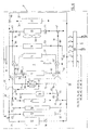
- Figures 1 to 4 illustrate the operation of the device in four main situations, respectively cold start in summer, stabilized operation, i.e. outside the start-up phase, in summer, cold start in winter, and stabilized operation in winter.
- the situation “in summer”, respectively “in winter” refers to a situation requiring cooling, respectively heating, of the passenger compartment.
- the compressor 3 When the compressor 3 is running ( Figures 1, 2 and 3), the refrigerant compressed by the compressor 3 condenses, at least in part, in the condenser 5 in producing heat energy, then is expanded by regulator 7, evaporates then, at least in part, in the evaporator 9 producing energy before being compressed again by compressor 3.
- the circuit traversed by the refrigerant is short and the quantity of this the latter necessary for the operation of the device according to the invention is therefore low.
- the operation of the secondary circuit is adapted to each situation:
- the three-way valve 64 can be positioned to allow circulation of the heat transfer fluid through the cold storage system 65.
- the energy refrigerator previously stored in system 65 in situations where the refrigeration requirements of the different heat exchangers were lower than production of cooling energy in the evaporator 9, is transferred to the heat transfer fluid.
- compressor 3 allows advantageously to reduce the power required from the fuel cell in a situation where its temperature is not optimal and its performance is bad.
- the fuel cell must be reheated to reach an optimal operating temperature, i.e. allowing good energy efficiency.
- the heat transfer fluid circulated by the pump 38, is heated by calories produced by the condensation of the refrigerant in the condenser 5 when crossing the latter. Thus heated, it successively crosses the valves 57 and 47 to the stack exchanger 12 where it releases heat energy to the pile, before returning, via valves 43 and 55 until condenser 5.
- the heat transfer fluid thus circulates in a loop in a second independent sub-circuit of the first, i.e. the heat transfer fluid not mix with that circulating in the first sub-circuit.
- a fraction of the coolant cooled in from the battery exchanger 12 passes through the water condenser 19 there reheating, condensing, at least in part, the water vapor from the cell and brought into contact with the water condenser 19.
- the crossing of the water condenser 19 also makes it possible, advantageously, to provide part of the heat energy intended for the battery, and therefore relieve the compressor 3 and / or accelerate the heating of the stack, especially when the need for air conditioning in the passenger compartment is low.
- the supply of heat energy to the stack must stop:
- the three-way valves 43 and 47 change position so as to isolate the battery exchanger 12 from the heat transfer fluid having passed through the condenser 5 and to connect the radiator 20 and the pump 45 to the water condenser 19 and to the condenser 5.
- the pump 45 is started, thus , possibly, that the fan 28.
- the heat transfer fluid cooled by passing through the radiator 20, passes through heating the water condenser 19 and the condenser 5.
- the heat energy produced in the latter is not desired and is discharged through the radiator 20. This production of heat energy is however necessary to allow production of cooling energy in the evaporator 9.
- the pump 38 preferably remains on and the three-way valve 48 is positioned so that the heat transfer fluid from the cell exchanger 12, which cannot no longer cross the first radiator 20, or diverted into the branch branch 37.
- the circulation of the heat transfer fluid then no longer has the objective of heating the stack, but, advantageously, to homogenize its temperature.
- Table 1 indicates the positions of the various organs of the device according to the invention.
- Compressor 3 is running to produce energy refrigeration by evaporation of the refrigerant in the evaporator 9. After having passed through the evaporator 9, the heat transfer fluid passes through the air heater 16 and the heat exchangers 17 and 18 to transfer cooling energy to the passenger compartment, batteries and electronic components, respectively.
- the cooling capacity transmitted to the passenger compartment is weaker than that transmitted at start-up, the air heater 16 having smaller dimensions than those of the air heater 15.
- the energy consumed by compressor 3 therefore remains low despite the need to cool, in addition to the passenger compartment, the batteries and electronic components.
- the two air heaters 15 and 16 are of powers different heat exchange.
- the heater 16 is smaller than the air heater 15. This difference between these air heaters allows modularity advantageous for optimizing the energy consumption of the compressor.
- Use of the cooling energy stored in the storage system 65 advantageously makes it possible to further increase the cooling power delivered to the passenger compartment.
- the heat energy transferred to the heat transfer fluid in the condenser 5 and in the water condenser 19 is discharged to the outside of the vehicle V via the radiator 20, as in the situation described above for cold start in summer , when the temperature of the battery T 1 exceeds 60 ° C.
- the secondary circuit thus comprises three sub-circuits independent corresponding to the battery cooling circuits, interior, battery and component group cooling electronics, and condenser cooling 5.
- the valves 40 and 41 are positioned so that part of the heat transfer fluid leaving the cell exchanger 12 is cooled to through the heater 15, which can no longer be used to cool the passenger compartment.
- the air coming from outside and heating in contact with the heater 15 is advantageously returned to the outside, so as not to contribute to the passenger compartment heating.
- the means of diverting the air flow to the outside are described in more detail below ( Figure 5).
- the air heater 15 can therefore be used selectively as an air heater or an external radiator.
- the valve 39 is open, thus authorizing the passage of the exchanger 14 by the fluid coolant from the stack. Fresh air coming out of the passenger compartment towards the exterior and passing through the exchanger 14 thus cools the heat transfer fluid before it does not return to cool the fuel cell.
- Part of the refrigeration transferred into the passenger compartment via the heater 16 is therefore used to cool the battery. This characteristic is particularly advantageous, these frigories being otherwise rejected towards the outside and lost.
- Compressor 3 is running, but valve positions at four tracks 55 and 57 are reversed, so that the heat energy transferred to the heat transfer fluid in the condenser 5 is transported to the air heaters 15 and 16 to heat the passenger compartment and so that the cooling energy transferred to the heat transfer fluid in the evaporator 9 is discharged to the outside by through the radiator 20.
- the valve 64 can also be positioned from so as to recharge the storage system with cooling energy, if necessary cold 65.
- radiator 20 At the outlet of the radiator 20, a fraction of the heat transfer fluid passes through the water condenser 19, releasing frigories so as to condense the vapor of water from the stack, then reheated, mixes with the fluid coolant from evaporator 9 before returning to radiator 20.
- the radiator 20 can therefore selectively serve as a means for evacuating heat or cooling energy to the outside.
- FIG. 3 illustrates the situation where the battery, batteries and components electronics need no thermal power.
- the secondary circuit has two sub-circuits independent heating of the passenger compartment and evacuation of frigories by the radiator 20.
- a circulation of heat transfer fluid in a loop through the branches 31, 49, 37 and 50 can advantageously be established to homogenize the temperature of the battery and / or provide the flow required for the humidifier of the battery.
- valves three-way 40 and 41 are positioned so that heat transfer fluid from the condenser 5 passes through the battery exchanger 12.
- the compressor 3 is stopped, which allows a energy saving.
- the heat energy produced by the battery and transported by the fluid is partially evacuated to the outside via the radiator 21 and / or the heater 15, and / or is evacuated to the passenger compartment by means of the exchanger 14 and / or the air heater 15.
- the operation of the air heater 15, which allows an evacuation of calories towards the cabin or towards outside, is described in more detail in the following description ( Figure 5).
- valve 23 is open so that the heat transfer fluid leaving the battery exchanger 12 can also be advantageously cooled by the dehumidifier regenerator 13.
- the valve 39 can also be opened, so that the fresh air leaving the passenger compartment and passing through the exchanger 14 also contributes, advantageously, to this cooling.
- valves 40, 41 and 68 can also be fully opened from so that part of the heat transfer fluid leaving the battery exchanger 12 crosses the heater 16 to heat the passenger compartment.
- a fraction of the fluid coolant from the stack exchanger 12 can mix with the fluid coolant from exchangers 17, 18 and 19 before entering the radiator 20 to be cooled.
- This fraction must be determined so that the temperature heat transfer fluid returning to exchangers 17, 18 and 19 always allows a satisfactory cooling of batteries and electronic components and a sufficient condensation of water vapor from the piercing cell the exchanger 19.
- FIG. 4 illustrates the situation in which all means of cooling of the heat transfer fluid from the cell exchanger 12 are implemented.
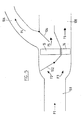
- FIG. 5 illustrates a device intended to optimize the efficiency of unit heaters 15 and 16.
- This device comprises a pipe 101 for supplying outside air, a first shutter 102, a second shutter 104, and pipes 106 and 108 exhaust air to the outside and to the passenger compartment, respectively.
- the position of the second flap 104 determines the fractions of the air having passed through the air heater 15 evacuated to the outside (arrow F4) via line 106 and to the passenger compartment (arrow F5) via line 108, respectively.
- the air having passed through the heater 16 is discharged towards the passenger compartment (arrow F6) via line 108.
- this device makes it possible to transform the air heater 15 into heating or air conditioning element of the passenger compartment, or as a means of evacuation of energy to the outside of vehicle V.
- the device according to the invention allows thermal regulation of one or more exchangers, and in particular the selection of the production of heat energy or cooling energy in this exchanger, by action on the selective connection means inserted in the secondary circuit.
- the refrigerant circuit is reduced to a simple loop and may not have only one compressor, one condenser, one regulator and one evaporator. The refrigerant volume is thus reduced to a minimum amount.
- the different exchangers of the secondary circuit can be in heat exchange relationship with any organs, in particular different from those described, with the passenger compartment of the vehicle or with the exterior of the vehicle.
- an exchanger such as exchanger 20 or exchanger 12 can be in heat exchange relationship with the battery, the exterior, the passenger compartment, the batteries or other parts of the vehicle.
- the invention therefore relates to a device thermal management of one or more exchangers arranged according to an architecture as illustrated in FIGS. 1 to 4, or equivalent, independently of the destination of the heat or cooling energy transferred by this or these exchangers.
Applications Claiming Priority (2)
| Application Number | Priority Date | Filing Date | Title |
|---|---|---|---|
| FR0111603 | 2001-09-07 | ||
| FR0111603A FR2829432B1 (fr) | 2001-09-07 | 2001-09-07 | Dispositif de gestion thermique, notamment pour vehicule automobile equipe d'une pile a combustible |
Publications (2)
| Publication Number | Publication Date |
|---|---|
| EP1291206A1 true EP1291206A1 (de) | 2003-03-12 |
| EP1291206B1 EP1291206B1 (de) | 2008-05-07 |
Family
ID=8867070
Family Applications (1)
| Application Number | Title | Priority Date | Filing Date |
|---|---|---|---|
| EP20020292192 Expired - Fee Related EP1291206B1 (de) | 2001-09-07 | 2002-09-06 | Vorrichtung zur Temperaturregelung, insbesondere für ein Kraftfahrzeug |
Country Status (4)
| Country | Link |
|---|---|
| EP (1) | EP1291206B1 (de) |
| DE (1) | DE60226384D1 (de) |
| ES (1) | ES2301611T3 (de) |
| FR (1) | FR2829432B1 (de) |
Cited By (18)
| Publication number | Priority date | Publication date | Assignee | Title |
|---|---|---|---|---|
| EP2192286A2 (de) * | 2008-11-26 | 2010-06-02 | Scania CV AB (PUBL) | Verfahren und System für die zusätzliche Kühlung des Kühlmittels im Kühlsystem eines Fahrzeuges |
| DE102010038406A1 (de) * | 2010-07-26 | 2012-01-26 | Behr Gmbh & Co. Kg | System für ein Kraftfahrzeug zum Erwärmen und/oder Kühlen eines Kraftfahrzeuginnenraumes und zum Kühlen eines Verbrennungsmotors |
| WO2013045089A1 (de) * | 2011-09-30 | 2013-04-04 | Volkswagen Aktiengesellschaft | Thermisches konditionieren eines, insbesondere einen elektroantrieb aufweisenden kraftfahrzeugs |
| FR2988468A1 (fr) * | 2012-03-23 | 2013-09-27 | Peugeot Citroen Automobiles Sa | Dispositif d'echange de calories avec des fluides externes de temperatures differentes, par transfert alterne de fluide interne entre des chambres de reaction |
| DE102012108043A1 (de) * | 2012-08-30 | 2014-05-15 | Dr. Ing. H.C. F. Porsche Aktiengesellschaft | Temperierungsanordnung |
| EP2873541A1 (de) * | 2013-11-18 | 2015-05-20 | Valeo Systemes Thermiques | Kühlsystem für die Batterien eines Elektro- oder Hybridfahrzeugs |
| DE102014217960A1 (de) * | 2014-09-09 | 2016-03-10 | Bayerische Motoren Werke Aktiengesellschaft | Wärmepumpenanlage zur Klimatisierung eines Fahrzeuges und Verfahren zum Betrieb einer solchen Wärmepumpenanlage |
| US20160238327A1 (en) * | 2015-02-05 | 2016-08-18 | Buerkert Werke Gmbh | Process valve manifold and heat exchanger system |
| DE102015222267A1 (de) * | 2015-11-11 | 2017-05-11 | Mahle International Gmbh | Klimaanlage |
| US9682611B2 (en) | 2014-03-18 | 2017-06-20 | Mahle International Gmbh | Air conditioning system |
| CN108501658A (zh) * | 2018-06-12 | 2018-09-07 | 上海加冷松芝汽车空调股份有限公司 | 一种热管理系统及汽车 |
| CN112290112A (zh) * | 2019-07-22 | 2021-01-29 | Fca意大利股份公司 | 用于电驱动车辆的被提供有帕耳帖单元的热调节系统 |
| CN112703120A (zh) * | 2018-09-12 | 2021-04-23 | 法雷奥热系统公司 | 传热液体回路 |
| CN114407604A (zh) * | 2021-12-08 | 2022-04-29 | 重庆长安汽车股份有限公司 | 一种集成式电动汽车热管理系统、控制方法及电动汽车 |
| CN115139778A (zh) * | 2021-09-30 | 2022-10-04 | 比亚迪股份有限公司 | 热管理系统和具有其的车辆 |
| US20220388368A1 (en) * | 2021-06-02 | 2022-12-08 | Guangzhou Automobile Group Co., Ltd. | Thermal management system and electric vehicle having the same |
| WO2022263050A1 (de) * | 2021-06-17 | 2022-12-22 | HELLA GmbH & Co. KGaA | Kühlsystem für ein kraftfahrzeug und verfahren zum betrieb eines kühlsystems |
| WO2023051146A1 (zh) * | 2021-09-30 | 2023-04-06 | 比亚迪股份有限公司 | 车辆的热管理系统以及车辆 |
Families Citing this family (3)
| Publication number | Priority date | Publication date | Assignee | Title |
|---|---|---|---|---|
| US10272744B2 (en) | 2015-09-03 | 2019-04-30 | Ford Global Technologies, Llc | Vehicle HVAC system with auxiliary coolant loop for heating and cooling vehicle interior |
| US10513166B2 (en) | 2015-09-03 | 2019-12-24 | Ford Global Technologies, Llc | Vehicle HVAC system with auxiliary coolant loop for heating and cooling vehicle interior |
| CN110920914B (zh) * | 2019-12-06 | 2021-04-06 | 南京航空航天大学 | 一种飞机综合热管理调节系统 |
Citations (6)
| Publication number | Priority date | Publication date | Assignee | Title |
|---|---|---|---|---|
| US5265437A (en) * | 1990-11-26 | 1993-11-30 | Modine Manufacturing Co. | Automotive refrigeration system requiring minimal refrigerant |
| EP0595714A1 (de) * | 1992-10-26 | 1994-05-04 | Valeo Thermique Habitacle | Klimaanlage insbesondere für Elektrofahrzeug |
| DE19542125A1 (de) * | 1994-11-29 | 1996-05-30 | Bayerische Motoren Werke Ag | Heiz- und Kühlmittelkreislauf für ein Elektrofahrzeug |
| FR2766261A1 (fr) * | 1997-07-18 | 1999-01-22 | Valeo Thermique Moteur Sa | Dispositif de climatisation de vehicule avec boucle de refrigerant resserree |
| FR2780490A1 (fr) * | 1998-06-30 | 1999-12-31 | Valeo Climatisation | Systeme de reglage de la temperature dans l'habitacle d'un vehicule a moteur electrique |
| FR2805926A1 (fr) | 2000-03-03 | 2001-09-07 | Renault | Dispositif de gestion thermique d'un vehicule equipe d'une pile a combustible |
-
2001
- 2001-09-07 FR FR0111603A patent/FR2829432B1/fr not_active Expired - Fee Related
-
2002
- 2002-09-06 EP EP20020292192 patent/EP1291206B1/de not_active Expired - Fee Related
- 2002-09-06 ES ES02292192T patent/ES2301611T3/es not_active Expired - Lifetime
- 2002-09-06 DE DE60226384T patent/DE60226384D1/de not_active Expired - Lifetime
Patent Citations (6)
| Publication number | Priority date | Publication date | Assignee | Title |
|---|---|---|---|---|
| US5265437A (en) * | 1990-11-26 | 1993-11-30 | Modine Manufacturing Co. | Automotive refrigeration system requiring minimal refrigerant |
| EP0595714A1 (de) * | 1992-10-26 | 1994-05-04 | Valeo Thermique Habitacle | Klimaanlage insbesondere für Elektrofahrzeug |
| DE19542125A1 (de) * | 1994-11-29 | 1996-05-30 | Bayerische Motoren Werke Ag | Heiz- und Kühlmittelkreislauf für ein Elektrofahrzeug |
| FR2766261A1 (fr) * | 1997-07-18 | 1999-01-22 | Valeo Thermique Moteur Sa | Dispositif de climatisation de vehicule avec boucle de refrigerant resserree |
| FR2780490A1 (fr) * | 1998-06-30 | 1999-12-31 | Valeo Climatisation | Systeme de reglage de la temperature dans l'habitacle d'un vehicule a moteur electrique |
| FR2805926A1 (fr) | 2000-03-03 | 2001-09-07 | Renault | Dispositif de gestion thermique d'un vehicule equipe d'une pile a combustible |
Cited By (30)
| Publication number | Priority date | Publication date | Assignee | Title |
|---|---|---|---|---|
| EP2192286A2 (de) * | 2008-11-26 | 2010-06-02 | Scania CV AB (PUBL) | Verfahren und System für die zusätzliche Kühlung des Kühlmittels im Kühlsystem eines Fahrzeuges |
| EP2192286A3 (de) * | 2008-11-26 | 2012-08-08 | Scania CV AB (PUBL) | Verfahren und System für die zusätzliche Kühlung des Kühlmittels im Kühlsystem eines Fahrzeuges |
| CN101734142B (zh) * | 2008-11-26 | 2015-02-18 | 斯堪尼亚商用车有限公司 | 用于额外冷却交通工具冷却系统中的冷却剂的方法和系统 |
| DE102010038406A1 (de) * | 2010-07-26 | 2012-01-26 | Behr Gmbh & Co. Kg | System für ein Kraftfahrzeug zum Erwärmen und/oder Kühlen eines Kraftfahrzeuginnenraumes und zum Kühlen eines Verbrennungsmotors |
| WO2013045089A1 (de) * | 2011-09-30 | 2013-04-04 | Volkswagen Aktiengesellschaft | Thermisches konditionieren eines, insbesondere einen elektroantrieb aufweisenden kraftfahrzeugs |
| FR2988468A1 (fr) * | 2012-03-23 | 2013-09-27 | Peugeot Citroen Automobiles Sa | Dispositif d'echange de calories avec des fluides externes de temperatures differentes, par transfert alterne de fluide interne entre des chambres de reaction |
| DE102012108043A1 (de) * | 2012-08-30 | 2014-05-15 | Dr. Ing. H.C. F. Porsche Aktiengesellschaft | Temperierungsanordnung |
| FR3013269A1 (fr) * | 2013-11-18 | 2015-05-22 | Valeo Systemes Thermiques | Systeme de refroidissement des batteries d'un vehicule electrique ou hybride |
| CN104659440A (zh) * | 2013-11-18 | 2015-05-27 | 法雷奥热系统公司 | 用于冷却电动或混合动力车辆的电池的系统 |
| EP2873541A1 (de) * | 2013-11-18 | 2015-05-20 | Valeo Systemes Thermiques | Kühlsystem für die Batterien eines Elektro- oder Hybridfahrzeugs |
| CN104659440B (zh) * | 2013-11-18 | 2019-02-01 | 法雷奥热系统公司 | 用于冷却电动或混合动力车辆的电池的系统 |
| US9682611B2 (en) | 2014-03-18 | 2017-06-20 | Mahle International Gmbh | Air conditioning system |
| DE102014217960A1 (de) * | 2014-09-09 | 2016-03-10 | Bayerische Motoren Werke Aktiengesellschaft | Wärmepumpenanlage zur Klimatisierung eines Fahrzeuges und Verfahren zum Betrieb einer solchen Wärmepumpenanlage |
| US10611210B2 (en) | 2014-09-09 | 2020-04-07 | Bayerische Motoren Werke Aktiengesellschaft | Heat pump system for climate control of a vehicle, and method for operating a heat pump system of this type |
| US20160238327A1 (en) * | 2015-02-05 | 2016-08-18 | Buerkert Werke Gmbh | Process valve manifold and heat exchanger system |
| US10866037B2 (en) * | 2015-02-05 | 2020-12-15 | Buerkert Werke Gmbh | Process valve manifold and heat exchanger system |
| US11052722B2 (en) | 2015-11-11 | 2021-07-06 | Mahle International Gmbh | Air-conditioning system |
| DE102015222267A1 (de) * | 2015-11-11 | 2017-05-11 | Mahle International Gmbh | Klimaanlage |
| CN108501658A (zh) * | 2018-06-12 | 2018-09-07 | 上海加冷松芝汽车空调股份有限公司 | 一种热管理系统及汽车 |
| CN108501658B (zh) * | 2018-06-12 | 2024-03-08 | 上海松芝酷能汽车技术有限公司 | 一种热管理系统及汽车 |
| CN112703120A (zh) * | 2018-09-12 | 2021-04-23 | 法雷奥热系统公司 | 传热液体回路 |
| CN112290112A (zh) * | 2019-07-22 | 2021-01-29 | Fca意大利股份公司 | 用于电驱动车辆的被提供有帕耳帖单元的热调节系统 |
| CN112290112B (zh) * | 2019-07-22 | 2024-04-02 | Fca意大利股份公司 | 用于电驱动车辆的被提供有帕耳帖单元的热调节系统 |
| US20220388368A1 (en) * | 2021-06-02 | 2022-12-08 | Guangzhou Automobile Group Co., Ltd. | Thermal management system and electric vehicle having the same |
| US11548349B2 (en) * | 2021-06-02 | 2023-01-10 | Guangzhou Automobile Group Co., Ltd. | Thermal management system and electric vehicle having the same |
| WO2022263050A1 (de) * | 2021-06-17 | 2022-12-22 | HELLA GmbH & Co. KGaA | Kühlsystem für ein kraftfahrzeug und verfahren zum betrieb eines kühlsystems |
| CN115139778A (zh) * | 2021-09-30 | 2022-10-04 | 比亚迪股份有限公司 | 热管理系统和具有其的车辆 |
| WO2023051146A1 (zh) * | 2021-09-30 | 2023-04-06 | 比亚迪股份有限公司 | 车辆的热管理系统以及车辆 |
| CN114407604A (zh) * | 2021-12-08 | 2022-04-29 | 重庆长安汽车股份有限公司 | 一种集成式电动汽车热管理系统、控制方法及电动汽车 |
| CN114407604B (zh) * | 2021-12-08 | 2024-04-19 | 重庆长安汽车股份有限公司 | 一种集成式电动汽车热管理系统、控制方法及电动汽车 |
Also Published As
| Publication number | Publication date |
|---|---|
| FR2829432B1 (fr) | 2005-06-24 |
| ES2301611T3 (es) | 2008-07-01 |
| FR2829432A1 (fr) | 2003-03-14 |
| DE60226384D1 (de) | 2008-06-19 |
| EP1291206B1 (de) | 2008-05-07 |
Similar Documents
| Publication | Publication Date | Title |
|---|---|---|
| EP1329344B1 (de) | Anordnung zur thermischen Verwaltung, insbesondere für ein Fahrzeug, das mit einer Brennstoffzelle ausgerüstet ist | |
| EP1291206B1 (de) | Vorrichtung zur Temperaturregelung, insbesondere für ein Kraftfahrzeug | |
| EP2643643B2 (de) | Vorrichtung zur wärmeregelung eines insassenraums eines fahrzeuges | |
| EP2632748B1 (de) | Vorrichtung zur thermischen konditionierung eines fahrzeugantriebs und eines fahrzeuginnenraums | |
| EP1282535B1 (de) | Vorrichtung und verfahren zur klimatisierung des innenraums von kraftfahrzeugen | |
| EP2933586A1 (de) | Kältekreislauf | |
| FR2851503A1 (fr) | Appareil de ventilation, de chauffage et/ou de climatisation pour habitacle de vehicule automobile a refroidissement simultane d'air et d'un fluide caloporteur | |
| EP3781882B1 (de) | Wärmeregelungsvorrichtung für ein kraftfahrzeug | |
| FR2936445A1 (fr) | Systeme de chauffage et climatisation ameliore pour vehicule automobile | |
| EP3899225A1 (de) | Vorrichtung zur thermischen behandlung eines wärmetransferflüssigkeitskreises eines hybridfahrzeugs | |
| FR3076342A1 (fr) | Circuit de conditionnement thermique | |
| EP2102575A1 (de) | Wärmetauscher mit mindestens drei wärmeaustauschteilen und wärmeenergieverwaltungssystem mit solch einem tauscher | |
| EP3263374A1 (de) | Reversibler klimatisierungskreislauf für ein kraftfahrzeug, und entsprechende funktionsweisen | |
| WO2015003894A1 (fr) | Système de conditionnement thermique pour véhicule automobile, installation de chauffage, ventilation et/ou climatisation correspondante et procédé de pilotage correspondant | |
| EP3511182B1 (de) | Klimaanlagensystem mit fünfwegeventilen, modul und entsprechendes verfahren | |
| EP1261053A1 (de) | Anordnung zur thermischen Verwaltung eines Fahrzeuges, ausgerüstet mit einer Brennstoffzelle | |
| WO2019186077A1 (fr) | Système de conditionnement thermique d'un dispositif de stockage électrique équipant un véhicule | |
| WO2008025916A1 (fr) | Systeme de climatisation pour vehicule automobile | |
| FR3078389A1 (fr) | Installation thermique pour moteurs thermique et electrique avec transmission automatique electrique et condenseur fluide/fluide | |
| WO2023198564A1 (fr) | Systeme de conditionnement thermique | |
| FR3013265A1 (fr) | Systeme de conditionnement thermique d'un flux d'air pour vehicule automobile et installation de chauffage, ventilation et/ou climatisation correspondante | |
| WO2023186488A1 (fr) | Système de conditionnement thermique | |
| FR3077374A1 (fr) | Systeme de conditionnement d'air a modes de rechauffage/deshumidification a temperature ambiante positive optimises, module et procede correspondant | |
| WO2023025902A1 (fr) | Système de conditionnement thermique pour véhicule automobile | |
| WO2023198624A1 (fr) | Système de conditionnement thermique |
Legal Events
| Date | Code | Title | Description |
|---|---|---|---|
| PUAI | Public reference made under article 153(3) epc to a published international application that has entered the european phase |
Free format text: ORIGINAL CODE: 0009012 |
|
| AK | Designated contracting states |
Kind code of ref document: A1 Designated state(s): AT BE BG CH CY CZ DE DK EE ES FI FR GB GR IE IT LI LU MC NL PT SE SK TR |
|
| AX | Request for extension of the european patent |
Extension state: AL LT LV MK RO SI |
|
| 17P | Request for examination filed |
Effective date: 20030910 |
|
| AKX | Designation fees paid |
Designated state(s): BE DE ES FR GB |
|
| 17Q | First examination report despatched |
Effective date: 20070503 |
|
| GRAP | Despatch of communication of intention to grant a patent |
Free format text: ORIGINAL CODE: EPIDOSNIGR1 |
|
| GRAS | Grant fee paid |
Free format text: ORIGINAL CODE: EPIDOSNIGR3 |
|
| GRAA | (expected) grant |
Free format text: ORIGINAL CODE: 0009210 |
|
| AK | Designated contracting states |
Kind code of ref document: B1 Designated state(s): BE DE ES FR GB |
|
| REG | Reference to a national code |
Ref country code: GB Ref legal event code: FG4D Free format text: NOT ENGLISH |
|
| REF | Corresponds to: |
Ref document number: 60226384 Country of ref document: DE Date of ref document: 20080619 Kind code of ref document: P |
|
| REG | Reference to a national code |
Ref country code: ES Ref legal event code: FG2A Ref document number: 2301611 Country of ref document: ES Kind code of ref document: T3 |
|
| PLBE | No opposition filed within time limit |
Free format text: ORIGINAL CODE: 0009261 |
|
| STAA | Information on the status of an ep patent application or granted ep patent |
Free format text: STATUS: NO OPPOSITION FILED WITHIN TIME LIMIT |
|
| 26N | No opposition filed |
Effective date: 20090210 |
|
| PGFP | Annual fee paid to national office [announced via postgrant information from national office to epo] |
Ref country code: GB Payment date: 20120920 Year of fee payment: 11 |
|
| PGFP | Annual fee paid to national office [announced via postgrant information from national office to epo] |
Ref country code: ES Payment date: 20120926 Year of fee payment: 11 |
|
| PGFP | Annual fee paid to national office [announced via postgrant information from national office to epo] |
Ref country code: BE Payment date: 20120920 Year of fee payment: 11 |
|
| BERE | Be: lapsed |
Owner name: RENAULT S.A.S. Effective date: 20130930 |
|
| GBPC | Gb: european patent ceased through non-payment of renewal fee |
Effective date: 20130906 |
|
| PG25 | Lapsed in a contracting state [announced via postgrant information from national office to epo] |
Ref country code: GB Free format text: LAPSE BECAUSE OF NON-PAYMENT OF DUE FEES Effective date: 20130906 Ref country code: BE Free format text: LAPSE BECAUSE OF NON-PAYMENT OF DUE FEES Effective date: 20130930 |
|
| REG | Reference to a national code |
Ref country code: ES Ref legal event code: FD2A Effective date: 20150504 |
|
| PG25 | Lapsed in a contracting state [announced via postgrant information from national office to epo] |
Ref country code: ES Free format text: LAPSE BECAUSE OF NON-PAYMENT OF DUE FEES Effective date: 20130907 |
|
| REG | Reference to a national code |
Ref country code: FR Ref legal event code: PLFP Year of fee payment: 14 |
|
| PGFP | Annual fee paid to national office [announced via postgrant information from national office to epo] |
Ref country code: DE Payment date: 20150922 Year of fee payment: 14 |
|
| PGFP | Annual fee paid to national office [announced via postgrant information from national office to epo] |
Ref country code: FR Payment date: 20150922 Year of fee payment: 14 |
|
| REG | Reference to a national code |
Ref country code: DE Ref legal event code: R119 Ref document number: 60226384 Country of ref document: DE |
|
| REG | Reference to a national code |
Ref country code: FR Ref legal event code: ST Effective date: 20170531 |
|
| PG25 | Lapsed in a contracting state [announced via postgrant information from national office to epo] |
Ref country code: FR Free format text: LAPSE BECAUSE OF NON-PAYMENT OF DUE FEES Effective date: 20160930 Ref country code: DE Free format text: LAPSE BECAUSE OF NON-PAYMENT OF DUE FEES Effective date: 20170401 |