EP1291123B1 - Werkzeugmaschine zur mindestens 3-achsigen Bearbeitung von Werkstücken - Google Patents
Werkzeugmaschine zur mindestens 3-achsigen Bearbeitung von Werkstücken Download PDFInfo
- Publication number
- EP1291123B1 EP1291123B1 EP02007979A EP02007979A EP1291123B1 EP 1291123 B1 EP1291123 B1 EP 1291123B1 EP 02007979 A EP02007979 A EP 02007979A EP 02007979 A EP02007979 A EP 02007979A EP 1291123 B1 EP1291123 B1 EP 1291123B1
- Authority
- EP
- European Patent Office
- Prior art keywords
- guide
- machine tool
- driving
- guide rails
- side wall
- Prior art date
- Legal status (The legal status is an assumption and is not a legal conclusion. Google has not performed a legal analysis and makes no representation as to the accuracy of the status listed.)
- Expired - Lifetime
Links
- 238000003754 machining Methods 0.000 title claims description 4
- 238000006073 displacement reaction Methods 0.000 description 4
- 230000008878 coupling Effects 0.000 description 3
- 238000010168 coupling process Methods 0.000 description 3
- 238000005859 coupling reaction Methods 0.000 description 3
- 238000005520 cutting process Methods 0.000 description 3
- 239000004952 Polyamide Substances 0.000 description 1
- 230000001133 acceleration Effects 0.000 description 1
- 238000006243 chemical reaction Methods 0.000 description 1
- 238000010276 construction Methods 0.000 description 1
- 238000001816 cooling Methods 0.000 description 1
- 230000009365 direct transmission Effects 0.000 description 1
- 230000000694 effects Effects 0.000 description 1
- 230000005489 elastic deformation Effects 0.000 description 1
- 238000005516 engineering process Methods 0.000 description 1
- 239000004744 fabric Substances 0.000 description 1
- 238000012423 maintenance Methods 0.000 description 1
- 230000007257 malfunction Effects 0.000 description 1
- 239000000463 material Substances 0.000 description 1
- 229920002647 polyamide Polymers 0.000 description 1
- 238000005381 potential energy Methods 0.000 description 1
Images


Classifications
-
- B—PERFORMING OPERATIONS; TRANSPORTING
- B23—MACHINE TOOLS; METAL-WORKING NOT OTHERWISE PROVIDED FOR
- B23Q—DETAILS, COMPONENTS, OR ACCESSORIES FOR MACHINE TOOLS, e.g. ARRANGEMENTS FOR COPYING OR CONTROLLING; MACHINE TOOLS IN GENERAL CHARACTERISED BY THE CONSTRUCTION OF PARTICULAR DETAILS OR COMPONENTS; COMBINATIONS OR ASSOCIATIONS OF METAL-WORKING MACHINES, NOT DIRECTED TO A PARTICULAR RESULT
- B23Q1/00—Members which are comprised in the general build-up of a form of machine, particularly relatively large fixed members
- B23Q1/25—Movable or adjustable work or tool supports
- B23Q1/44—Movable or adjustable work or tool supports using particular mechanisms
- B23Q1/56—Movable or adjustable work or tool supports using particular mechanisms with sliding pairs only, the sliding pairs being the first two elements of the mechanism
- B23Q1/60—Movable or adjustable work or tool supports using particular mechanisms with sliding pairs only, the sliding pairs being the first two elements of the mechanism two sliding pairs only, the sliding pairs being the first two elements of the mechanism
- B23Q1/62—Movable or adjustable work or tool supports using particular mechanisms with sliding pairs only, the sliding pairs being the first two elements of the mechanism two sliding pairs only, the sliding pairs being the first two elements of the mechanism with perpendicular axes, e.g. cross-slides
- B23Q1/621—Movable or adjustable work or tool supports using particular mechanisms with sliding pairs only, the sliding pairs being the first two elements of the mechanism two sliding pairs only, the sliding pairs being the first two elements of the mechanism with perpendicular axes, e.g. cross-slides a single sliding pair followed perpendicularly by a single sliding pair
- B23Q1/626—Movable or adjustable work or tool supports using particular mechanisms with sliding pairs only, the sliding pairs being the first two elements of the mechanism two sliding pairs only, the sliding pairs being the first two elements of the mechanism with perpendicular axes, e.g. cross-slides a single sliding pair followed perpendicularly by a single sliding pair followed perpendicularly by a single sliding pair
-
- B—PERFORMING OPERATIONS; TRANSPORTING
- B23—MACHINE TOOLS; METAL-WORKING NOT OTHERWISE PROVIDED FOR
- B23Q—DETAILS, COMPONENTS, OR ACCESSORIES FOR MACHINE TOOLS, e.g. ARRANGEMENTS FOR COPYING OR CONTROLLING; MACHINE TOOLS IN GENERAL CHARACTERISED BY THE CONSTRUCTION OF PARTICULAR DETAILS OR COMPONENTS; COMBINATIONS OR ASSOCIATIONS OF METAL-WORKING MACHINES, NOT DIRECTED TO A PARTICULAR RESULT
- B23Q1/00—Members which are comprised in the general build-up of a form of machine, particularly relatively large fixed members
- B23Q1/25—Movable or adjustable work or tool supports
- B23Q1/44—Movable or adjustable work or tool supports using particular mechanisms
- B23Q1/48—Movable or adjustable work or tool supports using particular mechanisms with sliding pairs and rotating pairs
-
- B—PERFORMING OPERATIONS; TRANSPORTING
- B23—MACHINE TOOLS; METAL-WORKING NOT OTHERWISE PROVIDED FOR
- B23Q—DETAILS, COMPONENTS, OR ACCESSORIES FOR MACHINE TOOLS, e.g. ARRANGEMENTS FOR COPYING OR CONTROLLING; MACHINE TOOLS IN GENERAL CHARACTERISED BY THE CONSTRUCTION OF PARTICULAR DETAILS OR COMPONENTS; COMBINATIONS OR ASSOCIATIONS OF METAL-WORKING MACHINES, NOT DIRECTED TO A PARTICULAR RESULT
- B23Q1/00—Members which are comprised in the general build-up of a form of machine, particularly relatively large fixed members
- B23Q1/25—Movable or adjustable work or tool supports
- B23Q1/44—Movable or adjustable work or tool supports using particular mechanisms
- B23Q1/56—Movable or adjustable work or tool supports using particular mechanisms with sliding pairs only, the sliding pairs being the first two elements of the mechanism
-
- B—PERFORMING OPERATIONS; TRANSPORTING
- B23—MACHINE TOOLS; METAL-WORKING NOT OTHERWISE PROVIDED FOR
- B23Q—DETAILS, COMPONENTS, OR ACCESSORIES FOR MACHINE TOOLS, e.g. ARRANGEMENTS FOR COPYING OR CONTROLLING; MACHINE TOOLS IN GENERAL CHARACTERISED BY THE CONSTRUCTION OF PARTICULAR DETAILS OR COMPONENTS; COMBINATIONS OR ASSOCIATIONS OF METAL-WORKING MACHINES, NOT DIRECTED TO A PARTICULAR RESULT
- B23Q5/00—Driving or feeding mechanisms; Control arrangements therefor
- B23Q5/22—Feeding members carrying tools or work
- B23Q5/28—Electric drives
Definitions
- the invention relates to a machine tool according to the preamble of Claim 1.
- a machine tool is known from EP 0 893 196 A2, which one has frame-like stand on which an x-slide can be moved horizontally is led.
- x-slide is a y-slide guided vertically.
- the y-carriage in turn carries a work spindle that can be moved in the z direction.
- the The y slide is on two of the vertical bars of the x slide attached mutually facing guide rails slidably guided. Two guide rails are in series in the z direction and arranged parallel to each other.
- the y-slide is on the work area facing guide rails, each with two guide shoes guided while he on the guide rails facing away from the work area is guided with one guide shoe each.
- the determination of the y-carriage in the x-direction is achieved by having two in each x-direction spaced guide rails is guided.
- a machine tool is known from US Pat. No. 6,012,884 A, in which a x-slide on two vertically spaced horizontal Rail is slidable. There is a vertically movable one on the x-slide y-slide slidably arranged on two in the x-direction from each other spaced guide rails is guided.
- the guide rails are linear drives that are not described or shown in detail assigned.
- Linear guide systems are known from EP 0 861 990 A2, in which Brake shoes are provided.
- the invention has for its object a machine tool Generic type so that reliable guidance and a torsion-free drive is achieved with a compact design.
- a security system is in the guides integrated.
- a position measuring device can also be built into the structure according to the invention integrate according to claim 3.
- the machine tool shown in the drawing for at least 3-axis machining of workpieces using a rotary drive Tool has a cuboid stand 1, which consists of two to each other parallel vertical side walls 2, 3, a bottom 4 and one Upper part 5, which connect the side walls 2, 3 with each other.
- the Stand 1 encloses a so-called actuator space and interior 6 is open at its two end faces 7, 8.
- a work space 9 In front of one end 7 is a work space 9, where on one connected to the stand 1 Machine bed 10 arranged a workpiece holder 11 only indicated is.
- a work spindle 12 designed as a motor spindle arranged, which protrudes through the end face 7 into the working space 9 and a rotatably drivable tool 13 for machining a workpiece holder 11 arranged workpiece 14 carries.
- the front is 7 covered by a cover, not shown, during movements the work spindle 12 in the horizontal x direction and vertical y direction is moved, but not a main part of the stand 1, but only serves to separate the work space 9 from the interior 6.
- the work spindle 12 can be in the z-direction vertical to the x-y plane be movable; but it is also possible that the workpiece holder 11 in is known to be movable in the z direction.
- Each coupling 17, 18 is connected to the associated carriage 15, 16 by means of a Swivel joint 19, 20 connected to the axis of rotation 21, 22 extending in the z direction.
- the two couplers 17, 18 are in turn by means of a swivel joint 23 connected to each other with axis of rotation 24 extending in the z direction.
- a tube-like is adjacent to the swivel joint 23
- Work spindle carrier 25 attached, in which the work spindle 12th is arranged.
- the couplers 17, 18 are in connection with the drive slides 15, 16 designed so that the angle a, which the couplers 17, 18 enclose, when moving the work spindle 12 to any position in the whole Work area changes only by a small amount. This will causes the two couplers 17, 18 to stiffen each other, whereby the rigidity of the coupling kinematics of the work spindle 12 compared with other known machine tools, with simultaneous reduction the moving mass is increased. For this reason, lead the cutting edge of the tool 13 resulting cutting forces less deflection of the work spindle 12.
- the slides 15, 16 are spaced apart from one another in the z direction on the inside of the side walls 2 and 3 arranged guide rails 27, 28 slidably guided, for which they with guide shoes 29, 30 are provided which surround the guide rails 27, 28. Every guide rail 27, 28 forms together with the guide shoes running on it 29 or 30 a tour.
- Each on a side wall 2 or 3 attached guide rails 27, 28 and the corresponding Guide shoes 29, 30 are provided as drives for linear motors 31, 32.
- the respective primary part 33 of each linear motor 31, 32 is on the adjacent side wall 2 or 3 facing side between the pairs attached by guide shoes 29, 30.
- the power supply of the Primary parts 33 are made via only indicated electrical connections 34 assigned to each primary part 33, formed by magnetic plates 35a 35 of each linear motor 31 or 32 is between the pairs at a distance from one another on the inside of the respective side wall 2 or 3 arranged guide rails 27, 28 on the respective side wall 2 or 3 attached.
- Primary part 33 and secondary part 35 are each coolable by means of cooling devices 36, 37.
- each linear motor 31, 32 is determined by means of a distance measuring device 38, 39 recorded.
- the distance measuring devices 38, 39 are between the respective linear motor 31, 32 and the one adjacent to the working space 9 Guide 27, 29 and 28, 30 arranged.
- the ruler-like stationary Part 40 of each device 38, 39 is on the associated side wall 2, 3 attached, while the movable as a scanning device Part 41 is attached to the respective carriage 15, 16.
- the secondary parts 35, the guide rails 27, 28 and the fixed parts 40 of the displacement measuring devices 38, 39 are attached by means of screws 42, 43, 44 the inside of the respective side wall exposed to the working space 9 2 or 3 attached and therefore easily accessible and therefore easy can be assembled or disassembled.
- the arrangement of the linear motors 31, 32 between the guides 27 to 30 leads to a very torsionally rigid guide the carriage 15, 16.
- the attractive forces of the linear motor 31 or 32 introduced directly into the associated carriage 15 or 16 and thus cause a slight deformation of the slide 15 and 16.
- the rigid construction of the sled 15, 16 and the inexpensive Arrangement of the linear motors 31, 32 and the displacement measuring devices 38, 39 favor the control behavior of the machine tool and thus the processing quality.
- the simple assembly is possible, for example, in such a way that first the primary parts 33 are mounted on the respective slide 15 and 16 and then the carriage 15, 16 placed on the respective guide rails 27, 28 becomes. Then the carriage 15 or 16 in an upper or lower Move extreme position and a part of the secondary part 35 Magnetic plates 35a on the free area of the inside of each Side wall 2, 3 screwed. Then the respective carriage 15, 16 move to the other extreme position and then the other part of the Magnetic plates 35a screwed on.
- a weight compensation device 45 is provided, which essentially consist of a piston-cylinder unit Gas spring 46 is made, the piston rod 47 of which is on a lower bracket 48 of the respective carriage 15, 16 is attached.
- the gas spring 46 exerts the respective slides have an upward pulling force in the y direction through which the weight of the respective slide 15 or 16 with all is compensated by these worn parts.
- the couplers 17, 18 and the work spindle carrier 25 with the work spindle 12 can also be moved in the x direction, changes on the respective slide 15 or 16 weight force acting during the operation of the machine, so that a complete compensation of the weight forces via the weight balancing device 45 does not take place, but it is not important.
- the gas springs 46 can have a compressed air supply, not shown and a corresponding control going beyond the Weight balance for moving the slides 15 and 16 during maintenance work be used when powering the linear motors 31, 32 is switched off.
- 27 and 28 are assigned between the respective guide rails Guide shoes 29, 30 a brake shoe 49 arranged, the also attached to the respective carriage 15, 16 by means of screws 50 is.
- the brake shoes 49 are opened during operation by means of compressed air; in the event of an interruption in the voltage supply to the linear motors 31, 32, the brake shoes 49 are vented and close, so that the carriage 15, 16 on the guide rails 27, 28 as by means of a mechanical Parking brake to be held.
- 16 end position damper 51, 52 Associated with the bottom 4 and the upper part 5 are 15 for each slide, 16 end position damper 51, 52 provided, which corresponding stops 53, 54 are assigned to the respective carriage 15 and 16, respectively. This will ensures that these end position dampers 51 and 52 come into effect, if one of the slides 15, 16 the upper specified in the control or the lower maximum travel distance. It is also at a failure of the control or another malfunction conceivable that the relative distance between the two carriages 15, 16 in the vertical y direction with the result that the work spindle 12 becomes too horizontal x direction leaves the work area 26 and the work spindle carrier 25 against a side wall 2 or 3 including those attached there Parts beats.
- a distance limiter 55 is provided, which can consist, for example, of a flexible band 56, the ends of which are each via a pressure plate 57 on the underside of each Carriage 15, 16 is held with the carriage 15, 16 by means of screws 58 is connected.
- This flexible band 56 is so in its rigidity designed that if the linear motors 31, 32 fail, the kinetic Energy of the entire mass moved in the x-y plane - if necessary together with the end position dampers 51, 52 - dismantles or converts, without the work spindle carrier 25 or any other moving Part collides with a mechanical limitation.
- an energy conversion there is in particular an elastic deformation of the band 56 into consideration, which stores the energy as potential energy becomes.
- the flexible band 56 can be made of different materials.
- a polyamide fabric tape is preferably used, as is known from load handling devices from conveyor technology. Such However, bands do not convert all of the energy absorbed into them Heat around; rather, it happens at the end of such an emergency route a spring back.
- the emergency route is the route of the work spindle holder 25.
- the tape 56 experiences a permanent in such an emergency Elongation and must be replaced accordingly.
Landscapes
- Engineering & Computer Science (AREA)
- Mechanical Engineering (AREA)
- Machine Tool Units (AREA)
Description
- Fig. 1
- eine Stirnansicht der Werkzeugmaschine,
- Fig. 2
- einen Vertikal-Schnitt durch die Werkzeugmaschine entsprechend der Schnittlinie II-II in Fig. 1 und
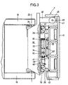
- Fig. 3
- einen horizontalen Teilschnitt durch die Werkzeugmaschine entsprechend der Schnittlinie III-III in Fig. 1.
Claims (4)
- Werkzeugmaschine zur mindestens 3-achsigen Bearbeitung von Werkstückendadurch gekennzeichnet, dass die Antriebs-Schlitten (15, 16) jeweils auf zwei in z-Richtung voneinander beabstandeten Führungsschienen (27, 28) verschiebbar geführt sind, wobei die Führungsschienen (27, 28) jeweils an der dem Innenraum (6) zugewandten, zum Innenraum (6) hin offenliegenden Seite der Seitenwand (2, 3) angeordnet sind, dass am jeweiligen Antriebs-Schlitten (15, 16) die Führungsschienen (27, 28) umfassende Führungsschuhe (29, 30) angebracht sind, wobei jede Führungsschiene (27, 28) zusammen mit den auf ihr laufenden Führungsschuhen (29, 30) eine Führung bildet, und dass die Antriebe als zwischen den Führungen angeordnete Linearmotoren (31, 32) ausgebildet sind, wobei jeweils ein erster Teil (33) der Linearmotoren (31, 32) am Antriebs-Schlitten (15, 16) und ein zweiter Teil (35) an der Seitenwand (2, 3) angebracht ist.mit einem gehäuseartigen Ständer (1), derSeitenwände (2, 3),einen Innenraum (6) undeine zu einem Arbeitsraum (9) hin offene Stirnseite (7) aufweist,mit einer im wesentlichen im Innenraum (6) angeordneten, in einer z-Richtung in den Arbeitsraum (9) ragenden Arbeitsspindel (12),mit je einem an jeder Seitenwand (2, 3) geradlinig in einer y-Richtung verschiebbar geführten Antriebs-Schlitten (15, 16),mit an den Antriebs-Schlitten (15, 16) mittels Drehgelenken (19, 20) angelenkten, mittels eines Drehgelenks (23) mit einander verbundenen Koppeln (17, 18), die die Arbeitsspindel (12) tragen, undmit Antrieben für die Antriebs-Schlitten (15, 16),
- Werkzeugmaschine nach Anspruch 1, dadurch gekennzeichnet, dass auf jeder Führungsschiene (27, 28) im Abstand voneinander zwei Führungsschuhe (29, 30) angeordnet sind, zwischen denen ein am Antriebs-Schlitten (15, 16) angebrachter Bremsschuh (49) angeordnet ist.
- Werkzeugmaschine nach einem der Ansprüche 1 oder 2, dadurch gekennzeichnet, dass zwischen einer Führung (27, 29) jedes Antriebs-Schlittens (15, 16) und dem Linearmotor (31, 32) eine Wegmess-Einrichtung (38, 39) vorgesehen ist.
- Werkzeugmaschine nach Anspruch 1, dadurch gekennzeichnet, dass die zweiten Teile (35) der Linearmotoren (31, 32) und die Führungsschienen (27, 28) vom Innenraum (6) her an die Seitenwand (2, 3) angeschraubt sind.
Priority Applications (1)
| Application Number | Priority Date | Filing Date | Title |
|---|---|---|---|
| US10/233,094 US6761518B2 (en) | 2001-09-11 | 2002-08-28 | Machine tool |
Applications Claiming Priority (2)
| Application Number | Priority Date | Filing Date | Title |
|---|---|---|---|
| DE10144541 | 2001-09-11 | ||
| DE10144541 | 2001-09-11 |
Publications (2)
| Publication Number | Publication Date |
|---|---|
| EP1291123A1 EP1291123A1 (de) | 2003-03-12 |
| EP1291123B1 true EP1291123B1 (de) | 2004-11-24 |
Family
ID=7698513
Family Applications (1)
| Application Number | Title | Priority Date | Filing Date |
|---|---|---|---|
| EP02007979A Expired - Lifetime EP1291123B1 (de) | 2001-09-11 | 2002-04-10 | Werkzeugmaschine zur mindestens 3-achsigen Bearbeitung von Werkstücken |
Country Status (3)
| Country | Link |
|---|---|
| EP (1) | EP1291123B1 (de) |
| DE (2) | DE10215582B4 (de) |
| ES (1) | ES2232692T3 (de) |
Families Citing this family (1)
| Publication number | Priority date | Publication date | Assignee | Title |
|---|---|---|---|---|
| CN104787378B (zh) * | 2015-04-17 | 2017-05-31 | 无锡科技职业学院 | 一种包装自动化操作装置 |
Citations (1)
| Publication number | Priority date | Publication date | Assignee | Title |
|---|---|---|---|---|
| EP0893196A2 (de) * | 1997-07-24 | 1999-01-27 | Toyoda Koki Kabushiki Kaisha | Werkzeugmaschine |
Family Cites Families (7)
| Publication number | Priority date | Publication date | Assignee | Title |
|---|---|---|---|---|
| DE4133411A1 (de) * | 1991-10-09 | 1993-04-15 | Zeiss Carl Jena Gmbh | Mess- und grenzweggebersystem zum schutz gegen ein ueberfahren einer oder mehrerer grenzlagen eines arbeitsbereiches durch bewegte teile einer maschine oder eines messgeraetes |
| FR2743741B1 (fr) * | 1996-01-23 | 1998-03-06 | Renault Automation | Structure logique d'une machine-outil d'usinage a grande vitesse du type porte-broche |
| DE29607680U1 (de) * | 1996-04-27 | 1996-06-20 | Carl Zeiss Jena Gmbh, 07745 Jena | Anordnung zur Verringerung der Crashgefahr bei universellen Positioniersystemen |
| DE19634575B4 (de) * | 1996-08-27 | 2004-03-04 | Pritschow, Günter, Prof. Dr.-Ing. Dr.h.c.mult. | Vorrichtung zur Erfassung der Position eines Werkzeug- und/oder eines Werkstückhalters |
| EP0861990B1 (de) * | 1997-02-28 | 2004-08-18 | Deutsche Star GmbH | Linearführungseinrichtung |
| DE19806085B4 (de) * | 1997-10-20 | 2004-11-11 | Cross Hüller GmbH | Werkzeugmaschine zur 3-achsigen Bearbeitung von Werkstücken |
| WO2000076704A1 (en) * | 1999-06-11 | 2000-12-21 | Unova I.P. Corporation | Machine tool drive system |
-
2002
- 2002-04-10 EP EP02007979A patent/EP1291123B1/de not_active Expired - Lifetime
- 2002-04-10 DE DE10215582A patent/DE10215582B4/de not_active Expired - Fee Related
- 2002-04-10 ES ES02007979T patent/ES2232692T3/es not_active Expired - Lifetime
- 2002-04-10 DE DE50201607T patent/DE50201607D1/de not_active Expired - Lifetime
Patent Citations (1)
| Publication number | Priority date | Publication date | Assignee | Title |
|---|---|---|---|---|
| EP0893196A2 (de) * | 1997-07-24 | 1999-01-27 | Toyoda Koki Kabushiki Kaisha | Werkzeugmaschine |
Also Published As
| Publication number | Publication date |
|---|---|
| DE50201607D1 (de) | 2004-12-30 |
| EP1291123A1 (de) | 2003-03-12 |
| DE10215582B4 (de) | 2006-04-13 |
| DE10215582A1 (de) | 2003-04-10 |
| ES2232692T3 (es) | 2005-06-01 |
Similar Documents
| Publication | Publication Date | Title |
|---|---|---|
| DE3420936C1 (de) | Schutzvorrichtung fuer die Fuehrungsbahn eines ersten Maschinenteiles,auf dem ein zweites Maschinenteil laengsbeweglich gelagert ist | |
| DE10017959C2 (de) | Lineararbeitsvorrichtung | |
| EP2132864B1 (de) | Elektrische lineardirektantriebsvorrichtung mit einem zwei führungsschienen zur linearführung eines angetriebenen schlittens aufweisender stator | |
| DE60000169T2 (de) | Hochgeschwindigheitsherstellungseinheit für Bearbeitungsvorgänge | |
| DE69838351T2 (de) | Werkzeugmaschine | |
| DE3100141C2 (de) | ||
| DE102017122439A1 (de) | Werkzeugmaschine mit vertikaler Spindel | |
| EP1105241B1 (de) | Werkzeugmaschine, insbesondere fräsbearbeitungszentrum | |
| EP0812652B1 (de) | Vorrichtung zur Bearbeitung und/oder Montage von Werkstücken | |
| DE3218712A1 (de) | Zweiachsiges handhabungsgeraet fuer werkstuecke, insbesondere zum be- und entladen von ebenen magazinen | |
| EP2326466A1 (de) | Luftkissenplattform zum tragen eines manipulatorarms und verfahrbarer roboter | |
| DE102008003816A1 (de) | Röntgeneinrichtung umfassend einen vorzugsweise an einem Roboterarm drehgelagerten C-Bogen | |
| DE19650360A1 (de) | Antriebseinheit für eine Maschine | |
| DE102019128931B4 (de) | Ausgleichseinheit für eine Automatisierungsanlage | |
| DE69914377T2 (de) | Numerisch gesteuerte werkzeugmaschine | |
| DE102012103554A1 (de) | Koordinatenmessgerät | |
| EP1056566B1 (de) | Linearantrieb | |
| DE102013226826A1 (de) | Linearmotoranordnung und Werkzeugmaschine mit einer Linearmotoranordnung | |
| DE102005041496A1 (de) | Werkzeugmaschine | |
| DE102012109489B4 (de) | Portalwerkzeugmaschine mit Kollisionsschutz | |
| DE10211055B4 (de) | Bewegungs- und/oder Positioniervorrichtung | |
| EP1238752A1 (de) | Werkzeugmaschine | |
| EP3342547B1 (de) | Positioniereinheit | |
| DE102015210914B4 (de) | Koordinatenmessgerät mit einer beweglichen Traverse sowie Verfahren zum Herstellen eines derartigen Koordinatenmessgeräts | |
| EP1291123A1 (de) | Werkzeugmaschine zur mindestens 3-achsigen Bearbeitung von Werkstücken |
Legal Events
| Date | Code | Title | Description |
|---|---|---|---|
| PUAI | Public reference made under article 153(3) epc to a published international application that has entered the european phase |
Free format text: ORIGINAL CODE: 0009012 |
|
| AK | Designated contracting states |
Designated state(s): AT BE CH CY DE DK ES FI FR GB GR IE IT LI LU MC NL PT SE TR Kind code of ref document: A1 Designated state(s): AT BE CH CY DE DK ES FI FR GB GR IE IT LI LU MC NL PT SE TR |
|
| AX | Request for extension of the european patent |
Extension state: AL LT LV MK RO SI |
|
| 17P | Request for examination filed |
Effective date: 20030603 |
|
| AKX | Designation fees paid |
Designated state(s): DE ES FR IT |
|
| 17Q | First examination report despatched |
Effective date: 20031121 |
|
| GRAP | Despatch of communication of intention to grant a patent |
Free format text: ORIGINAL CODE: EPIDOSNIGR1 |
|
| GRAS | Grant fee paid |
Free format text: ORIGINAL CODE: EPIDOSNIGR3 |
|
| GRAA | (expected) grant |
Free format text: ORIGINAL CODE: 0009210 |
|
| RAP1 | Party data changed (applicant data changed or rights of an application transferred) |
Owner name: CROSS HUELLER GMBH |
|
| AK | Designated contracting states |
Kind code of ref document: B1 Designated state(s): DE ES FR IT |
|
| REF | Corresponds to: |
Ref document number: 50201607 Country of ref document: DE Date of ref document: 20041230 Kind code of ref document: P |
|
| REG | Reference to a national code |
Ref country code: IE Ref legal event code: FG4D Free format text: GERMAN |
|
| REG | Reference to a national code |
Ref country code: ES Ref legal event code: FG2A Ref document number: 2232692 Country of ref document: ES Kind code of ref document: T3 |
|
| REG | Reference to a national code |
Ref country code: IE Ref legal event code: FD4D |
|
| ET | Fr: translation filed | ||
| PLBE | No opposition filed within time limit |
Free format text: ORIGINAL CODE: 0009261 |
|
| STAA | Information on the status of an ep patent application or granted ep patent |
Free format text: STATUS: NO OPPOSITION FILED WITHIN TIME LIMIT |
|
| 26N | No opposition filed |
Effective date: 20050825 |
|
| REG | Reference to a national code |
Ref country code: DE Ref legal event code: R081 Ref document number: 50201607 Country of ref document: DE Owner name: MAG IAS GMBH, DE Free format text: FORMER OWNER: CROSS HUELLER GMBH, 71636 LUDWIGSBURG, DE Effective date: 20110223 |
|
| PGFP | Annual fee paid to national office [announced via postgrant information from national office to epo] |
Ref country code: DE Payment date: 20110617 Year of fee payment: 10 |
|
| PGFP | Annual fee paid to national office [announced via postgrant information from national office to epo] |
Ref country code: FR Payment date: 20120511 Year of fee payment: 11 |
|
| PGFP | Annual fee paid to national office [announced via postgrant information from national office to epo] |
Ref country code: IT Payment date: 20120424 Year of fee payment: 11 |
|
| PGFP | Annual fee paid to national office [announced via postgrant information from national office to epo] |
Ref country code: ES Payment date: 20120423 Year of fee payment: 11 |
|
| REG | Reference to a national code |
Ref country code: DE Ref legal event code: R119 Ref document number: 50201607 Country of ref document: DE Effective date: 20121101 |
|
| REG | Reference to a national code |
Ref country code: FR Ref legal event code: ST Effective date: 20131231 |
|
| PG25 | Lapsed in a contracting state [announced via postgrant information from national office to epo] |
Ref country code: IT Free format text: LAPSE BECAUSE OF NON-PAYMENT OF DUE FEES Effective date: 20130410 Ref country code: FR Free format text: LAPSE BECAUSE OF NON-PAYMENT OF DUE FEES Effective date: 20130430 |
|
| REG | Reference to a national code |
Ref country code: ES Ref legal event code: FD2A Effective date: 20140606 |
|
| PG25 | Lapsed in a contracting state [announced via postgrant information from national office to epo] |
Ref country code: ES Free format text: LAPSE BECAUSE OF NON-PAYMENT OF DUE FEES Effective date: 20130411 |
|
| PG25 | Lapsed in a contracting state [announced via postgrant information from national office to epo] |
Ref country code: DE Free format text: LAPSE BECAUSE OF NON-PAYMENT OF DUE FEES Effective date: 20121101 |