EP1290629B1 - Vorrichtung zur auswertung von echtheitsmerkmalen mit beugungsstruktur - Google Patents
Vorrichtung zur auswertung von echtheitsmerkmalen mit beugungsstruktur Download PDFInfo
- Publication number
- EP1290629B1 EP1290629B1 EP01960243A EP01960243A EP1290629B1 EP 1290629 B1 EP1290629 B1 EP 1290629B1 EP 01960243 A EP01960243 A EP 01960243A EP 01960243 A EP01960243 A EP 01960243A EP 1290629 B1 EP1290629 B1 EP 1290629B1
- Authority
- EP
- European Patent Office
- Prior art keywords
- diffraction
- illumination source
- document
- camera
- ground
- Prior art date
- Legal status (The legal status is an assumption and is not a legal conclusion. Google has not performed a legal analysis and makes no representation as to the accuracy of the status listed.)
- Expired - Lifetime
Links
Images

Classifications
-
- G—PHYSICS
- G06—COMPUTING OR CALCULATING; COUNTING
- G06K—GRAPHICAL DATA READING; PRESENTATION OF DATA; RECORD CARRIERS; HANDLING RECORD CARRIERS
- G06K7/00—Methods or arrangements for sensing record carriers, e.g. for reading patterns
- G06K7/10—Methods or arrangements for sensing record carriers, e.g. for reading patterns by electromagnetic radiation, e.g. optical sensing; by corpuscular radiation
- G06K7/10544—Methods or arrangements for sensing record carriers, e.g. for reading patterns by electromagnetic radiation, e.g. optical sensing; by corpuscular radiation by scanning of the records by radiation in the optical part of the electromagnetic spectrum
- G06K7/10821—Methods or arrangements for sensing record carriers, e.g. for reading patterns by electromagnetic radiation, e.g. optical sensing; by corpuscular radiation by scanning of the records by radiation in the optical part of the electromagnetic spectrum further details of bar or optical code scanning devices
- G06K7/1094—Methods or arrangements for sensing record carriers, e.g. for reading patterns by electromagnetic radiation, e.g. optical sensing; by corpuscular radiation by scanning of the records by radiation in the optical part of the electromagnetic spectrum further details of bar or optical code scanning devices the record carrier being at least partially of the hologram type
-
- G—PHYSICS
- G06—COMPUTING OR CALCULATING; COUNTING
- G06K—GRAPHICAL DATA READING; PRESENTATION OF DATA; RECORD CARRIERS; HANDLING RECORD CARRIERS
- G06K19/00—Record carriers for use with machines and with at least a part designed to carry digital markings
- G06K19/06—Record carriers for use with machines and with at least a part designed to carry digital markings characterised by the kind of the digital marking, e.g. shape, nature, code
- G06K19/08—Record carriers for use with machines and with at least a part designed to carry digital markings characterised by the kind of the digital marking, e.g. shape, nature, code using markings of different kinds or more than one marking of the same kind in the same record carrier, e.g. one marking being sensed by optical and the other by magnetic means
- G06K19/10—Record carriers for use with machines and with at least a part designed to carry digital markings characterised by the kind of the digital marking, e.g. shape, nature, code using markings of different kinds or more than one marking of the same kind in the same record carrier, e.g. one marking being sensed by optical and the other by magnetic means at least one kind of marking being used for authentication, e.g. of credit or identity cards
- G06K19/16—Record carriers for use with machines and with at least a part designed to carry digital markings characterised by the kind of the digital marking, e.g. shape, nature, code using markings of different kinds or more than one marking of the same kind in the same record carrier, e.g. one marking being sensed by optical and the other by magnetic means at least one kind of marking being used for authentication, e.g. of credit or identity cards the marking being a hologram or diffraction grating
-
- G—PHYSICS
- G06—COMPUTING OR CALCULATING; COUNTING
- G06K—GRAPHICAL DATA READING; PRESENTATION OF DATA; RECORD CARRIERS; HANDLING RECORD CARRIERS
- G06K7/00—Methods or arrangements for sensing record carriers, e.g. for reading patterns
- G06K7/10—Methods or arrangements for sensing record carriers, e.g. for reading patterns by electromagnetic radiation, e.g. optical sensing; by corpuscular radiation
- G06K7/10544—Methods or arrangements for sensing record carriers, e.g. for reading patterns by electromagnetic radiation, e.g. optical sensing; by corpuscular radiation by scanning of the records by radiation in the optical part of the electromagnetic spectrum
- G06K7/10554—Moving beam scanning
- G06K7/10594—Beam path
- G06K7/10603—Basic scanning using moving elements
-
- G—PHYSICS
- G06—COMPUTING OR CALCULATING; COUNTING
- G06K—GRAPHICAL DATA READING; PRESENTATION OF DATA; RECORD CARRIERS; HANDLING RECORD CARRIERS
- G06K7/00—Methods or arrangements for sensing record carriers, e.g. for reading patterns
- G06K7/10—Methods or arrangements for sensing record carriers, e.g. for reading patterns by electromagnetic radiation, e.g. optical sensing; by corpuscular radiation
- G06K7/10544—Methods or arrangements for sensing record carriers, e.g. for reading patterns by electromagnetic radiation, e.g. optical sensing; by corpuscular radiation by scanning of the records by radiation in the optical part of the electromagnetic spectrum
- G06K7/10712—Fixed beam scanning
- G06K7/10722—Photodetector array or CCD scanning
-
- G—PHYSICS
- G03—PHOTOGRAPHY; CINEMATOGRAPHY; ANALOGOUS TECHNIQUES USING WAVES OTHER THAN OPTICAL WAVES; ELECTROGRAPHY; HOLOGRAPHY
- G03H—HOLOGRAPHIC PROCESSES OR APPARATUS
- G03H1/00—Holographic processes or apparatus using light, infrared or ultraviolet waves for obtaining holograms or for obtaining an image from them; Details peculiar thereto
- G03H1/0005—Adaptation of holography to specific applications
- G03H1/0011—Adaptation of holography to specific applications for security or authentication
Definitions
- the invention relates to a device for the evaluation of authenticity features Diffraction structure according to the preamble of claim 1.
- Such Device has become known, for example, with the subject WO 98/55963.
- a document to be examined placed on a glass plate and on the Document are arranged evaluating diffraction structures.
- a laser is present, with its beam on the in the document surface arranged diffraction structure that hits the beam characteristic in the form of a pattern bends and reflects.
- the so produced Diffraction pattern is projected onto photodiodes firmly positioned in a housing. These are placed in the places in the housing where the characteristic Diffraction pattern is expected. Depending on whether a photodiode is a Diffraction pattern receives or not, is then about the authenticity of the document decided.
- the photodiodes at certain, fixed locations must be arranged in the document tester, and It is assumed that the photodiodes exactly at this location the diffraction pattern receive. If, however, the diffraction structure on the document surface slightly shifted or changed, or another type of diffraction structure given on another document, the are positioned in fixed locations Photodiodes receive nothing. This has the disadvantage that the known device can only be used with limited field of application, because it is essentially only for a single document type.
- the publication WO 95/12860 discloses a device for the evaluation of Authenticity features with diffraction patterns on a document.
- the document is placed on a test surface and is illuminated by a light source.
- the authenticity feature to be examined diffracts the beam of the illumination source and projects the diffracted beam onto a screen. That of the Light source emitted light is by means of a lens system so focuses that the diffracted beam hits the image surface.
- the invention is therefore based on the object, a device of the above so-called type so that authenticity features with diffraction structures can be recognized on a document in much greater variety and the Verification of the authenticity of a document therefore independent of the place of the Attach the authenticity features with diffractive structures on the document.
- the device is characterized in that a provided for imaging the diffraction pattern screen movable is formed and provided thereon a mirror is provided by means of which the Rays of the illumination source in the rays, which are on the diffraction structure impinge, be diverted.
- projection surface is widely understood.
- a projection surface can in a first embodiment, a ground glass be provided, on which the Diffraction patterns are projected, below the screen a camera is arranged, which evaluates the diffraction pattern on the screen.
- the camera can only look at subregions of the screen and Evaluate subregions or it can be the entire surface of the ground glass in one single operation are evaluated.
- the for lighting the Diffraction structure provided in the document laser only in the X direction for example is designed to be movable, but is rigid in the Y direction.
- the laser may be immovable e.g. on the housing be fixed and not deflected itself, with the rays of the laser on a Rotating mirrors are steered, which rotating mirror on a certain Angular range is deflectable. Next is the deflected by the rotating mirror laser beam then via a corresponding, fixed in the housing, telecentric mirror on the diffraction structure in or on the document directed.
- the ground glass in the Y direction is formed movable and on the screen Deflection mirror is fixed, so that the generated by the laser Beam over the fixed on the movable screen fixed mirror is directed to the fixed diffraction structure in the document.
- the deflection mirror for the Laser beam occupies about the entire width of the focusing screen. This is with the Advantage associated that the screen itself are not moved in the Y direction got to.
- the width of the deflection mirror is much smaller than the width of the ground glass, so that the entire Focusing screen as well as in X- and Y-direction is movable and under the fixed diffraction structure can be moved, wherein in this Embodiment of the laser is then firmly coupled to the ground glass.
- the ground glass is omitted immediately and that of the diffraction structure reflected diffraction pattern directly on the evaluation of photosensitive sensors of a camera movable under the diffraction structure be projected.
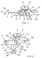
- Figure 1 is generally in a housing of a non-illustrated Dokumentprüfauss a laser 1 arranged, the beam 6 in a horizontal Sending out direction.
- the laser can be moved in the directions of the arrows 15, 16 formed, this corresponds to the movement of the laser in the X direction.
- the beam 6 generated by the laser 1 is profiled over an approximately dreoeclsförmig Mirror 3 reflected and in the form of a beam 7 against a fixed document 26, which may for example have a structure 4, in the area a diffraction structure 5 is arranged.
- the present invention is not based on the arrangement of Diffraction structure 5 limited in the region of a structure 4. It can Diffraction structures 5 also isolated in or on the document surface 26 be integrated.
- the ground glass 2 is in scanning directions 22 (this corresponds to the Y direction) under the fixed diffraction structure 5 movable arranged.
- the projected onto the diffraction structure 5 beam 7 of the laser 1 is thus in shape the diffracted beams 8, 9, 10 reflects and generates on the ground glass 2 for the Diffraction structure 5 characteristic diffraction patterns 11-13.
- the size, intensity and arrangement of diffraction patterns 11-13 on the Ground glass 2 is a measure of the authenticity of the diffraction structure 5 on the Document 26.
- FIG. 2 shows a modified embodiment in comparison to FIG It can be seen that the laser 1 via a holder 14 with the ground glass 2 connected is.
- the ground glass 2 is in the direction of arrows 15, 16, as well as in the Arrow directions 22 formed movable.
- This embodiment has the advantage that only a relatively small mirror 3 'may be provided, whose length is substantially smaller than the width of the Ground glass 2, in which case, however, the ground glass 2 in the X and Y directions must be designed movable.
- the Camera 18 is arranged below the ground glass 2, wherein the diffraction pattern on the image surface 21 of the CCD chip 20 is projected.
- FIG. 3 schematically shows a non-inventive example in which the ground glass 2 also completely eliminated, causing the diffraction pattern 11-12 is projected directly onto the image surface 21 of the CCD chip.
- FIG 4 shows schematically a structure of the device according to the invention, wherein here the laser 1 is fixed to the housing.
- the beams 6 generated by the laser 1 fall on a rotating mirror 23, which over a certain angular range ⁇ to a Rotary axis 25 is deflectable.
- the deflected by the rotating mirror 23 laser beam 6 ' is then passed through a housing-fixed, telecentric mirror 24 in the laser beam 6 "deflected and led to a deflection mirror 3, from where he as a laser beam 7 on the document 26 and its authenticity feature 4 with Diffraction structure 5 falls.
Landscapes
- Physics & Mathematics (AREA)
- Engineering & Computer Science (AREA)
- Electromagnetism (AREA)
- General Physics & Mathematics (AREA)
- Theoretical Computer Science (AREA)
- Health & Medical Sciences (AREA)
- General Health & Medical Sciences (AREA)
- Toxicology (AREA)
- Artificial Intelligence (AREA)
- Computer Vision & Pattern Recognition (AREA)
- Investigating Materials By The Use Of Optical Means Adapted For Particular Applications (AREA)
- Inspection Of Paper Currency And Valuable Securities (AREA)
- Investigating Or Analysing Materials By Optical Means (AREA)
- Optical Measuring Cells (AREA)
- Optical Record Carriers And Manufacture Thereof (AREA)
- Investigating, Analyzing Materials By Fluorescence Or Luminescence (AREA)
- Testing Of Optical Devices Or Fibers (AREA)
- Holo Graphy (AREA)
- Analysing Materials By The Use Of Radiation (AREA)
- Length Measuring Devices By Optical Means (AREA)
- Studio Devices (AREA)
- Credit Cards Or The Like (AREA)
Description
- Figur 1:
- schematisiert ein ersteS Ausführungsbeispiel nach der Erfindung;
- Figur 2:
- schematisiert ein gegenüber Figur 1 abgewandeltes Ausführungsbeispiel;
- Figur 3
- eine Ausführungsform der Vorrichtung, die nicht zur Erfindung gehört und
- Figur 4:
- eine dritte Ausführungsform der erfindungsgemäßen Vorrichtung.
- 1
- Laser
- 2
- Mattscheibe
- 3
- Spiegel 3'
- 4
- Echtheitsmerkmal
- 5
- Beugungsstruktur
- 6
- Strahl
- 7
- Strahl
- 8
- gebeugter Strahl
- 9
- gebeugter Strahl
- 10
- gebeugter Strahl
- 11
- Beugungsmuster
- 12
- Beugungsmuster
- 13
- Beugungsmuster
- 14
- Halterung
- 15
- Pfeilrichtung
- 16
- Pfeilrichtung
- 17
- Objektiv
- 18
- Kamera
- 19
- Strahlengang
- 20
- CCD-Chip
- 21
- Bildfläche
- 22
- Scanrichtung
- 23
- Drehspiegel
- 24
- telezentrischer Spiegel
- 25
- Drehachse
- 26
- Dokument
Claims (9)
- Vorrichtung zur Auswertung von Echtheitsmerkmalen (4) mit wenigstens einer Beugungsstruktur (5) auf einem Dokument (26), das auf einer Untersuchungsfläche aufgelegt ist, mit einer Beleuchtungsquelle (1), die das zu untersuchende Echtheitsmerkmal (4) anstrahlt, wobei eine Auswerte-Einheit (2,17,18,20,21 oder 18, 20, 21) vorgesehen ist, auf die der vom Echtheitsmerkmal gebeugte Strahl projiziert wird, mit einer Mattscheibe (2), auf die die von der Beugungsstruktur abgeleiteten Beugungsmuster (11,12,13) gelenkt werden, und einer Kamera (18), die das auf der Mattscheibe abgebildete Beugungsbild erfasst, dadurch gekennzeichnet, dass die Mattscheibe verfahrbar ausgebildet ist und ein darauf fest liegender Spiegel (3, 3') vorgesehen ist, mittels dem die Strahlen (6) der Beleuchtungsquelle (1) in die Strahlen (7), die auf die Beugungsstruktur (5) auftreffen, umgelenkt werden.
- Vorrichtung nach Anspruch 1, dadurch gekennzeichnet, dass die Kamera (18) eine Matrix- oder Zeilenkamera ist.
- Vorrichtung nach einem der Ansprüche 1 oder 2, dadurch gekennzeichnet, dass sich der Spiegel über die gesamte Breite der Mattscheibe erstreckt.
- Vorrichtung nach einem der Ansprüche 1 bis 3, dadurch gekennzeichnet, dass die Auswerte-Einheit das von der Kamera erfasste Bild auswertet.
- Vorrichtung nach Anspruch 4, dadurch gekennzeichnet, dass die Auswerte-Einheit (2, 17, 18, 20, 21) lediglich einen Teilbereich der Mattscheibe (2) auswertet.
- Vorrichtung nach einem der Ansprüche 1 bis 5, dadurch gekennzeichnet, dass die Beleuchtungsquelle (1) an der Mattscheibe (2) befestigt ist
- Vorrichtung nach einem der Ansprüche 1 bis 5, dadurch gekennzeichnet, dass die Beleuchtungsquelle (1) verfahrbar ausgebildet ist
- Vorrichtung nach einem der Ansprüche 1 bis 5, dadurch gekennzeichnet, dass die Beleuchtungsquelle (1) am Gehäuse feststehend ausgebildet ist und ein auslenkbarer Drehspiegel (23) vorgesehen ist, auf den die Strahlen (6) der Beleuchtungsquelle (1) gelenkt werden.
- Vorrichtung nach einem der Ansprüche 1 bis 8, dadurch gekennzeichnet, dass als Beleuchtungsquelle ein Laser vorgesehen ist.
Priority Applications (1)
| Application Number | Priority Date | Filing Date | Title |
|---|---|---|---|
| SI200130140T SI1290629T1 (en) | 2000-06-07 | 2001-05-25 | Device for evaluating authenticity features that have a diffraction structure |
Applications Claiming Priority (3)
| Application Number | Priority Date | Filing Date | Title |
|---|---|---|---|
| DE10028239A DE10028239A1 (de) | 2000-06-07 | 2000-06-07 | Vorrichtung zur Auswertung von Echtheitsmerkmalen mit Beugungsstruktur |
| DE10028239 | 2000-06-07 | ||
| PCT/EP2001/005989 WO2001095248A1 (de) | 2000-06-07 | 2001-05-25 | Vorrichtung zur auswertung von echtheitsmerkmalen mit beugungsstruktur |
Publications (2)
| Publication Number | Publication Date |
|---|---|
| EP1290629A1 EP1290629A1 (de) | 2003-03-12 |
| EP1290629B1 true EP1290629B1 (de) | 2004-07-28 |
Family
ID=7645028
Family Applications (1)
| Application Number | Title | Priority Date | Filing Date |
|---|---|---|---|
| EP01960243A Expired - Lifetime EP1290629B1 (de) | 2000-06-07 | 2001-05-25 | Vorrichtung zur auswertung von echtheitsmerkmalen mit beugungsstruktur |
Country Status (12)
| Country | Link |
|---|---|
| US (1) | US6750465B2 (de) |
| EP (1) | EP1290629B1 (de) |
| CN (1) | CN1201263C (de) |
| AT (1) | ATE272233T1 (de) |
| CA (1) | CA2411687C (de) |
| DE (2) | DE10028239A1 (de) |
| ES (1) | ES2225591T3 (de) |
| HU (1) | HU225352B1 (de) |
| PL (1) | PL198952B1 (de) |
| PT (1) | PT1290629E (de) |
| TR (1) | TR200402066T4 (de) |
| WO (1) | WO2001095248A1 (de) |
Families Citing this family (8)
| Publication number | Priority date | Publication date | Assignee | Title |
|---|---|---|---|---|
| DE10234431A1 (de) * | 2002-07-29 | 2004-02-12 | Giesecke & Devrient Gmbh | Vorrichtung und Verfahren zur Bearbeitung von Wertdokumenten |
| DE102004018856A1 (de) * | 2004-04-19 | 2005-11-03 | Giesecke & Devrient Gmbh | Vorrichtung zur Prüfung von Banknoten |
| DE102004020661A1 (de) * | 2004-04-24 | 2005-11-17 | Smiths Heimann Biometrics Gmbh | Anordnung und Verfahren zum Prüfen von optischen Beugungsstrukturen auf Dokumenten |
| US7830225B2 (en) * | 2005-06-13 | 2010-11-09 | Gale Robert D | Electric signal splitters |
| US7375533B2 (en) * | 2005-06-15 | 2008-05-20 | Gale Robert D | Continuity tester adaptors |
| DE102009017708B3 (de) * | 2009-04-14 | 2010-11-04 | Bundesdruckerei Gmbh | Verifikationsvorrichtung und Verfahren zum Verifizieren beugender und/oder reflektierender Sicherheitsmerkmale von Sicherheitsdokumenten |
| CN102500627B (zh) * | 2011-10-19 | 2013-12-18 | 北京金自天正智能控制股份有限公司 | 一种板材的宽度、边部形状、边部缺陷测量仪及测量方法 |
| DE102012219905A1 (de) * | 2012-10-31 | 2014-04-30 | Bundesdruckerei Gmbh | Verfahren und Vorrichtung zur Prüfung eines Sicherheitselements |
Citations (2)
| Publication number | Priority date | Publication date | Assignee | Title |
|---|---|---|---|---|
| WO1995012860A1 (en) * | 1993-11-05 | 1995-05-11 | Mikoh Technology Limited | Diffraction viewing device |
| US5508801A (en) * | 1993-01-19 | 1996-04-16 | Kabushikigaisya Hutech | Method and apparatus for nondestructive testing of the mechanical behavior of objects under loading utilizing wave theory of plastic deformation |
Family Cites Families (10)
| Publication number | Priority date | Publication date | Assignee | Title |
|---|---|---|---|---|
| US4184700A (en) | 1975-11-17 | 1980-01-22 | Lgz Landis & Gyr Zug Ag | Documents embossed with optical markings representing genuineness information |
| EP0375833B1 (de) | 1988-12-12 | 1993-02-10 | Landis & Gyr Technology Innovation AG | Optisch variables Flächenmuster |
| EP0587669A4 (de) * | 1991-06-05 | 1995-02-22 | Mikoh Pty Ltd | Brechungsgitter enthaltende, optische speicher. |
| JP2795595B2 (ja) * | 1992-06-26 | 1998-09-10 | セントラル硝子株式会社 | 透明板状体の欠点検出方法 |
| GB9425232D0 (en) * | 1994-12-14 | 1995-02-08 | Secr Defence | Method of authenticating watermarked paper |
| DE19721525A1 (de) | 1997-05-22 | 1998-12-24 | Hsm Gmbh | Verfahren zur Echtheitsprüfung eines Hologramms und Lesegerät zur Durchführung des Verfahrens |
| CH693693A5 (de) * | 1997-06-06 | 2003-12-15 | Ovd Kinegram Ag | Vorrichtung zum Erkennen beugungsoptischer Markierungen. |
| EP1003027B1 (de) * | 1997-06-17 | 2003-08-27 | Yuki Engineering System Co, Ltd. | Vorrichtung zur optischen prüfung von verpackungsfolien |
| US5825475A (en) * | 1997-07-29 | 1998-10-20 | Van Leer Metallized Products (Usa) Limited | System and method for determining which of a plurality of visually indistinguishable objects have been marked with a covert indicator |
| US6097035A (en) * | 1999-02-22 | 2000-08-01 | Digital Persona, Inc. | Fingerprint detection apparatus with partial fingerprint images |
-
2000
- 2000-06-07 DE DE10028239A patent/DE10028239A1/de not_active Withdrawn
-
2001
- 2001-05-25 PT PT01960243T patent/PT1290629E/pt unknown
- 2001-05-25 TR TR2004/02066T patent/TR200402066T4/xx unknown
- 2001-05-25 CN CNB018091148A patent/CN1201263C/zh not_active Expired - Lifetime
- 2001-05-25 WO PCT/EP2001/005989 patent/WO2001095248A1/de not_active Ceased
- 2001-05-25 HU HU0300702A patent/HU225352B1/hu unknown
- 2001-05-25 DE DE50103021T patent/DE50103021D1/de not_active Expired - Lifetime
- 2001-05-25 EP EP01960243A patent/EP1290629B1/de not_active Expired - Lifetime
- 2001-05-25 PL PL359019A patent/PL198952B1/pl unknown
- 2001-05-25 CA CA002411687A patent/CA2411687C/en not_active Expired - Lifetime
- 2001-05-25 AT AT01960243T patent/ATE272233T1/de active
- 2001-05-25 ES ES01960243T patent/ES2225591T3/es not_active Expired - Lifetime
-
2002
- 2002-11-25 US US10/373,884 patent/US6750465B2/en not_active Expired - Lifetime
Patent Citations (2)
| Publication number | Priority date | Publication date | Assignee | Title |
|---|---|---|---|---|
| US5508801A (en) * | 1993-01-19 | 1996-04-16 | Kabushikigaisya Hutech | Method and apparatus for nondestructive testing of the mechanical behavior of objects under loading utilizing wave theory of plastic deformation |
| WO1995012860A1 (en) * | 1993-11-05 | 1995-05-11 | Mikoh Technology Limited | Diffraction viewing device |
Also Published As
| Publication number | Publication date |
|---|---|
| DE10028239A1 (de) | 2001-12-13 |
| ATE272233T1 (de) | 2004-08-15 |
| CA2411687C (en) | 2007-01-30 |
| HU225352B1 (en) | 2006-10-28 |
| HUP0300702A2 (en) | 2003-08-28 |
| PL198952B1 (pl) | 2008-08-29 |
| DE50103021D1 (de) | 2004-09-02 |
| CA2411687A1 (en) | 2002-12-06 |
| CN1427981A (zh) | 2003-07-02 |
| CN1201263C (zh) | 2005-05-11 |
| ES2225591T3 (es) | 2005-03-16 |
| TR200402066T4 (tr) | 2004-10-21 |
| PT1290629E (pt) | 2004-11-30 |
| US6750465B2 (en) | 2004-06-15 |
| WO2001095248A1 (de) | 2001-12-13 |
| EP1290629A1 (de) | 2003-03-12 |
| US20030174308A1 (en) | 2003-09-18 |
| PL359019A1 (en) | 2004-08-23 |
Similar Documents
| Publication | Publication Date | Title |
|---|---|---|
| DE69314059T2 (de) | Einrichtung zum teilchennachweis mit spiegelnder zeile-zu-fleck umsetzender sammeloptik | |
| DE3410421C2 (de) | Verfahren und Vorrichtung zum Erfassen einer linienförmigen ersten Markierung und einer linienförmigen zweiten Markierung | |
| DE2256736B2 (de) | Meßanordnung zur automatischen Prüfung der Oberflächenbeschaffenheit und Ebenheit einer Werkstückoberfläche | |
| DE2827704C3 (de) | Optische Vorrichtung zur Bestimmung der Lichtaustrittswinkel | |
| EP1956366A1 (de) | Verfahren und Vorrichtung zur Detektierung von Defekten | |
| DE2802286C2 (de) | ||
| DE69722551T2 (de) | Spektrometer mit einem orientiert-geformten Schlitz | |
| DE3926349A1 (de) | Optische fehlerinspektionsvorrichtung | |
| DE3147689A1 (de) | Zusatzgeraet zur durchfuehrung von reflexionsmessungen mit einem ir-spektrometer | |
| DE3905730A1 (de) | Positionsmesseinrichtung | |
| EP1813961B1 (de) | Vorrichtung zur optoelektronischen Überwachung von Objekten | |
| EP1467185B1 (de) | Linsenanordnung für einen optischen Encoder | |
| EP2276999B1 (de) | Optische anordnung zur beleuchtung eines messobjektes und interferometrische anordnung zur vermessung von flächen eines messobjektes | |
| WO2001095248A1 (de) | Vorrichtung zur auswertung von echtheitsmerkmalen mit beugungsstruktur | |
| EP2500716B1 (de) | Vorrichtung zur optischen Erfassung von Prüfobjekten | |
| DE69117499T2 (de) | Geteilter, als v-dach gestalteter spiegelkollektor | |
| DE69321703T2 (de) | Tragbarer Strichmarkierungsleser mit erweiterter Schärfentiefe | |
| DE19737170A1 (de) | Optisches Kaskade-Abtastsystem | |
| DE2718711C2 (de) | ||
| DE2800351B2 (de) | Optische Vorrichtung zur Bestimmung des Lichtaustrittswinkels bei einer mit einem Lichtfleck abgetasteten Materialbahn | |
| DE10159234A1 (de) | Vorrichtung zur Untersuchung von Dokumenten | |
| EP1506445A1 (de) | Kompakte vorrichtung zur anamorphotischen abbildung der oberfläche von gegenständen unter verwendung eines reflektierenden prismas | |
| DE69934458T2 (de) | Optischer Abtaster mit verschiedenen Auflösungen | |
| DE10063786A1 (de) | Vorrichtung und Verfahren zum Vermessen eines Gegenstandes | |
| EP0916971A2 (de) | Schaltbares, mikrooptisches Strahlenumlenksystem |
Legal Events
| Date | Code | Title | Description |
|---|---|---|---|
| PUAI | Public reference made under article 153(3) epc to a published international application that has entered the european phase |
Free format text: ORIGINAL CODE: 0009012 |
|
| 17P | Request for examination filed |
Effective date: 20020926 |
|
| AK | Designated contracting states |
Kind code of ref document: A1 Designated state(s): AT BE CH CY DE DK ES FI FR GB GR IE IT LI LU MC NL PT SE TR Designated state(s): AT BE CH CY DE DK ES FI FR GB GR IE IT LI LU MC NL PT SE TR |
|
| AX | Request for extension of the european patent |
Extension state: LT LV RO SI |
|
| 17Q | First examination report despatched |
Effective date: 20030724 |
|
| GRAP | Despatch of communication of intention to grant a patent |
Free format text: ORIGINAL CODE: EPIDOSNIGR1 |
|
| RIC1 | Information provided on ipc code assigned before grant |
Ipc: 7G 06K 19/16 B Ipc: 7G 06K 7/10 A |
|
| GRAS | Grant fee paid |
Free format text: ORIGINAL CODE: EPIDOSNIGR3 |
|
| GRAA | (expected) grant |
Free format text: ORIGINAL CODE: 0009210 |
|
| AK | Designated contracting states |
Kind code of ref document: B1 Designated state(s): AT BE CH CY DE DK ES FI FR GB GR IE IT LI LU MC NL PT SE TR |
|
| AX | Request for extension of the european patent |
Extension state: SI |
|
| REG | Reference to a national code |
Ref country code: GB Ref legal event code: FG4D Free format text: NOT ENGLISH |
|
| REG | Reference to a national code |
Ref country code: CH Ref legal event code: EP |
|
| REG | Reference to a national code |
Ref country code: IE Ref legal event code: FG4D Free format text: GERMAN |
|
| REF | Corresponds to: |
Ref document number: 50103021 Country of ref document: DE Date of ref document: 20040902 Kind code of ref document: P |
|
| GBT | Gb: translation of ep patent filed (gb section 77(6)(a)/1977) |
Effective date: 20040917 |
|
| RAP2 | Party data changed (patent owner data changed or rights of a patent transferred) |
Owner name: BUNDESDRUCKEREI GMBH |
|
| REG | Reference to a national code |
Ref country code: GR Ref legal event code: EP Ref document number: 20040402929 Country of ref document: GR |
|
| PG25 | Lapsed in a contracting state [announced via postgrant information from national office to epo] |
Ref country code: DK Free format text: LAPSE BECAUSE OF FAILURE TO SUBMIT A TRANSLATION OF THE DESCRIPTION OR TO PAY THE FEE WITHIN THE PRESCRIBED TIME-LIMIT Effective date: 20041028 Ref country code: SE Free format text: LAPSE BECAUSE OF FAILURE TO SUBMIT A TRANSLATION OF THE DESCRIPTION OR TO PAY THE FEE WITHIN THE PRESCRIBED TIME-LIMIT Effective date: 20041028 |
|
| REG | Reference to a national code |
Ref country code: PT Ref legal event code: SC4A Free format text: AVAILABILITY OF NATIONAL TRANSLATION Effective date: 20040928 |
|
| NLT2 | Nl: modifications (of names), taken from the european patent patent bulletin |
Owner name: BUNDESDRUCKEREI GMBH |
|
| REG | Reference to a national code |
Ref country code: SI Ref legal event code: IF |
|
| LTIE | Lt: invalidation of european patent or patent extension |
Effective date: 20040728 |
|
| REG | Reference to a national code |
Ref country code: ES Ref legal event code: FG2A Ref document number: 2225591 Country of ref document: ES Kind code of ref document: T3 |
|
| ET | Fr: translation filed | ||
| PG25 | Lapsed in a contracting state [announced via postgrant information from national office to epo] |
Ref country code: LU Free format text: LAPSE BECAUSE OF NON-PAYMENT OF DUE FEES Effective date: 20050525 |
|
| PG25 | Lapsed in a contracting state [announced via postgrant information from national office to epo] |
Ref country code: MC Free format text: LAPSE BECAUSE OF NON-PAYMENT OF DUE FEES Effective date: 20050531 |
|
| PLBE | No opposition filed within time limit |
Free format text: ORIGINAL CODE: 0009261 |
|
| STAA | Information on the status of an ep patent application or granted ep patent |
Free format text: STATUS: NO OPPOSITION FILED WITHIN TIME LIMIT |
|
| 26N | No opposition filed |
Effective date: 20050429 |
|
| PG25 | Lapsed in a contracting state [announced via postgrant information from national office to epo] |
Ref country code: CY Free format text: LAPSE BECAUSE OF NON-PAYMENT OF DUE FEES Effective date: 20080525 |
|
| REG | Reference to a national code |
Ref country code: FR Ref legal event code: PLFP Year of fee payment: 16 |
|
| REG | Reference to a national code |
Ref country code: FR Ref legal event code: PLFP Year of fee payment: 17 |
|
| REG | Reference to a national code |
Ref country code: FR Ref legal event code: PLFP Year of fee payment: 18 |
|
| PGFP | Annual fee paid to national office [announced via postgrant information from national office to epo] |
Ref country code: ES Payment date: 20200618 Year of fee payment: 20 Ref country code: TR Payment date: 20200520 Year of fee payment: 20 Ref country code: IE Payment date: 20200519 Year of fee payment: 20 Ref country code: DE Payment date: 20200525 Year of fee payment: 20 Ref country code: NL Payment date: 20200518 Year of fee payment: 20 Ref country code: GR Payment date: 20200518 Year of fee payment: 20 Ref country code: CH Payment date: 20200522 Year of fee payment: 20 Ref country code: FR Payment date: 20200519 Year of fee payment: 20 Ref country code: PT Payment date: 20200518 Year of fee payment: 20 Ref country code: FI Payment date: 20200515 Year of fee payment: 20 Ref country code: CY Payment date: 20200513 Year of fee payment: 20 |
|
| PGFP | Annual fee paid to national office [announced via postgrant information from national office to epo] |
Ref country code: IT Payment date: 20200528 Year of fee payment: 20 Ref country code: GB Payment date: 20200522 Year of fee payment: 20 Ref country code: BE Payment date: 20200518 Year of fee payment: 20 |
|
| PGFP | Annual fee paid to national office [announced via postgrant information from national office to epo] |
Ref country code: AT Payment date: 20200515 Year of fee payment: 20 |
|
| REG | Reference to a national code |
Ref country code: DE Ref legal event code: R071 Ref document number: 50103021 Country of ref document: DE |
|
| REG | Reference to a national code |
Ref country code: NL Ref legal event code: MK Effective date: 20210524 |
|
| REG | Reference to a national code |
Ref country code: CH Ref legal event code: PL |
|
| REG | Reference to a national code |
Ref country code: FI Ref legal event code: MAE |
|
| REG | Reference to a national code |
Ref country code: GB Ref legal event code: PE20 Expiry date: 20210524 |
|
| REG | Reference to a national code |
Ref country code: IE Ref legal event code: MK9A |
|
| REG | Reference to a national code |
Ref country code: BE Ref legal event code: MK Effective date: 20210525 |
|
| REG | Reference to a national code |
Ref country code: AT Ref legal event code: MK07 Ref document number: 272233 Country of ref document: AT Kind code of ref document: T Effective date: 20210525 |
|
| PG25 | Lapsed in a contracting state [announced via postgrant information from national office to epo] |
Ref country code: PT Free format text: LAPSE BECAUSE OF EXPIRATION OF PROTECTION Effective date: 20210603 |
|
| PG25 | Lapsed in a contracting state [announced via postgrant information from national office to epo] |
Ref country code: GB Free format text: LAPSE BECAUSE OF EXPIRATION OF PROTECTION Effective date: 20210524 Ref country code: IE Free format text: LAPSE BECAUSE OF EXPIRATION OF PROTECTION Effective date: 20210525 |
|
| REG | Reference to a national code |
Ref country code: ES Ref legal event code: FD2A Effective date: 20210901 |
|
| PG25 | Lapsed in a contracting state [announced via postgrant information from national office to epo] |
Ref country code: ES Free format text: LAPSE BECAUSE OF EXPIRATION OF PROTECTION Effective date: 20210526 |
|
| PG25 | Lapsed in a contracting state [announced via postgrant information from national office to epo] |
Ref country code: TR Free format text: LAPSE BECAUSE OF NON-PAYMENT OF DUE FEES Effective date: 20210525 |