EP1289869B1 - Vorrichtung zum vertikalen transportieren von produkten - Google Patents
Vorrichtung zum vertikalen transportieren von produkten Download PDFInfo
- Publication number
- EP1289869B1 EP1289869B1 EP01919215A EP01919215A EP1289869B1 EP 1289869 B1 EP1289869 B1 EP 1289869B1 EP 01919215 A EP01919215 A EP 01919215A EP 01919215 A EP01919215 A EP 01919215A EP 1289869 B1 EP1289869 B1 EP 1289869B1
- Authority
- EP
- European Patent Office
- Prior art keywords
- load unit
- coolant
- permanent magnet
- mouldings
- superconducting
- Prior art date
- Legal status (The legal status is an assumption and is not a legal conclusion. Google has not performed a legal analysis and makes no representation as to the accuracy of the status listed.)
- Expired - Lifetime
Links
- 239000002826 coolant Substances 0.000 claims abstract description 36
- 235000012431 wafers Nutrition 0.000 claims abstract description 7
- 239000004065 semiconductor Substances 0.000 claims abstract description 6
- 238000000465 moulding Methods 0.000 claims description 20
- IJGRMHOSHXDMSA-UHFFFAOYSA-N Atomic nitrogen Chemical compound N#N IJGRMHOSHXDMSA-UHFFFAOYSA-N 0.000 claims description 6
- 238000004804 winding Methods 0.000 claims description 6
- 239000000945 filler Substances 0.000 claims description 5
- 238000001816 cooling Methods 0.000 claims description 4
- 239000010949 copper Substances 0.000 claims description 4
- 229910045601 alloy Inorganic materials 0.000 claims description 3
- 239000000956 alloy Substances 0.000 claims description 3
- 239000007788 liquid Substances 0.000 claims description 3
- 230000007246 mechanism Effects 0.000 claims description 3
- 229910001172 neodymium magnet Inorganic materials 0.000 claims description 3
- 229910052757 nitrogen Inorganic materials 0.000 claims description 3
- RYGMFSIKBFXOCR-UHFFFAOYSA-N Copper Chemical compound [Cu] RYGMFSIKBFXOCR-UHFFFAOYSA-N 0.000 claims description 2
- 229910052802 copper Inorganic materials 0.000 claims description 2
- 239000004020 conductor Substances 0.000 claims 1
- 229910021521 yttrium barium copper oxide Inorganic materials 0.000 claims 1
- 238000005299 abrasion Methods 0.000 abstract description 4
- 238000004377 microelectronic Methods 0.000 description 3
- 238000004519 manufacturing process Methods 0.000 description 2
- 239000012811 non-conductive material Substances 0.000 description 2
- 230000035939 shock Effects 0.000 description 2
- 239000002887 superconductor Substances 0.000 description 2
- 230000000712 assembly Effects 0.000 description 1
- 238000000429 assembly Methods 0.000 description 1
- 230000008878 coupling Effects 0.000 description 1
- 238000010168 coupling process Methods 0.000 description 1
- 238000005859 coupling reaction Methods 0.000 description 1
- 230000006866 deterioration Effects 0.000 description 1
- 239000000428 dust Substances 0.000 description 1
- 230000000694 effects Effects 0.000 description 1
- 238000003754 machining Methods 0.000 description 1
- 239000000463 material Substances 0.000 description 1
- 239000002245 particle Substances 0.000 description 1
- 238000003860 storage Methods 0.000 description 1
Images



Classifications
-
- H—ELECTRICITY
- H02—GENERATION; CONVERSION OR DISTRIBUTION OF ELECTRIC POWER
- H02K—DYNAMO-ELECTRIC MACHINES
- H02K41/00—Propulsion systems in which a rigid body is moved along a path due to dynamo-electric interaction between the body and a magnetic field travelling along the path
- H02K41/02—Linear motors; Sectional motors
- H02K41/03—Synchronous motors; Motors moving step by step; Reluctance motors
- H02K41/031—Synchronous motors; Motors moving step by step; Reluctance motors of the permanent magnet type
-
- H—ELECTRICITY
- H02—GENERATION; CONVERSION OR DISTRIBUTION OF ELECTRIC POWER
- H02K—DYNAMO-ELECTRIC MACHINES
- H02K7/00—Arrangements for handling mechanical energy structurally associated with dynamo-electric machines, e.g. structural association with mechanical driving motors or auxiliary dynamo-electric machines
- H02K7/08—Structural association with bearings
- H02K7/09—Structural association with bearings with magnetic bearings
Definitions
- the invention relates to a device for vertical Transporting products, especially for Processing plants of semiconductor wafers and discs.
- the device is particularly advantageous for production of integrated semiconductor products in cleanrooms in Can be used in connection with transport systems where the products to be processed between different levels are to be transported.
- Transport systems for the microelectronics industry are subject to special requirements for clean room suitability.
- Transport z. B. of containers (wafer cassettes - carrier or Pods) for wafer structuring in microelectronics a considerable technical and financial effort required.
- the transport system is in usually under the ceiling of the clean room areas in one length arranged by several kilometers (DE 197 37 839 A1).
- the Containers must have a variety of lifts in the Working height of the equipment are transported and remain between the individual machining processes in several Interim storage (stocker) in the transport system.
- the products to be processed usually remain several Weeks in the production process and are repeated several times between the individual processing areas and equipment via the Transport system transported back and forth, taking the products are stored in an open container.
- the previously known lifts contain a container with wafers or other microelectronic assemblies and a drive with Motor, motion converter, slide and guide.
- the invention has for its object a device for vertical transport of products, especially for Processing plants of semiconductor wafers and discs, so too design that no mechanical abrasion can occur and mechanical shocks are largely avoided.
- the device according to the invention stands out known lifts in processing plants for integrated Semiconductor products in particular characterized in that the Load unit and the drive are designed without friction pairing and are coupled without contact, so that none mechanical abrasion can occur. So that's it Device according to the invention in an excellent manner for the Suitable for use in cleanrooms.
- the device according to the invention can be in the following way be designed to be advantageous and / or expedient:
- the magnetized superconducting moldings can on the Load unit and the permanent magnet rails arranged stationary his. However, it is also a mutually reversed arrangement possible.
- the magnetized superconducting molded body should be arranged on the load unit expediently with a coolant tank for receiving the Coolant for cooling the magnetized superconducting Shaped body to be equipped.
- the coolant tank can advantageously be an annular channel for the Have coolant circulation and must with a Filler neck for the coolant.
- the filler neck in the lower and / or the upper end position of the load unit with a Coolant reservoir for reloading coolant be connected.
- Liquid nitrogen can be used as the coolant be used.
- the magnetized superconducting moldings can in the Wall of the coolant container can be arranged and on it Cooling coolant on the back.
- the magnetized superconducting moldings can advantageously consist of YBa 2 Cu 3 O 7 .
- the permanent magnet rails can be made up of Poled magnetically across the longitudinal axis of the rail Permanent magnetic disks exist, with adjacent ones Permanent magnetic plates transverse to the longitudinal axis one have magnetic polarity of the same name.
- the permanent magnet plates can for example be made of an Nd-Fe-B alloy consist.
- the load unit compared to the position reached on the load unit located magnetized superconducting molded body can in expediently a magnet arrangement with a defined distance to impress the in the superconducting moldings magnetic field to be frozen.
- the Dimension the distance so that the distance between the load unit and Permanent magnet rails results in the desired air gap size. It is useful if the size of the air gap between Load unit and permanent magnet rails to a value between 0.15 mm and 2.0 mm is set.
- magnetized superconducting Shaped bodies are arranged under a vacuum-tight cover. This should be made of a non-magnetic and electrical non-conductive material.
- the device with one or more Precision mechanisms for adjusting the position and the Angular position of the magnetic components must be equipped.
- the system can be used for electromagnetic linear drives permanent magnetically excited pole stationary and that current-fed coil system to be arranged on the load unit.
- the winding of the current-fed coil system can be useful be designed as a two-phase winding.
- the system of permanently magnetically excited poles can be one-sided or advantageously on both sides to the current-fed coil system be arranged. If the arrangement is on both sides, poles with magnetic of the same name or with magnetic of the same name Face polarity.
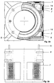
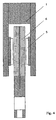
- a load unit 2 is located in a shaft-like housing 1 arranged, which consists of a loading deck 3 and a Coolant tank 4 exists (Fig. 1a, 1b and 2).
- the Load unit 2 is in the shaft-like housing 1 by magnetic components transported in the vertical direction and held contact-free to the housing 1.
- Permanent magnet rails 12 arranged vertically. These consist of individual lined up permanent magnet plates 13 from a Nd-Fe-B alloy. The arrangement is chosen so that juxtaposed permanent magnet plates 13 a have magnetic polarity of the same name (Fig. 5).
- the molded bodies 7 are on the load unit 2 behind one vacuum-tight cover 14 arranged, which consists of a non-magnetic and electrically non-conductive material.
- the load unit 2 is initially at a distance from the shaped bodies 7 of 0.5 mm positioned in relation to a permanent magnet arrangement been identical in terms of their magnetic field to that the magnetic rails 12 is.
- the molded body 7 in this Position has been cooled to a temperature of 77 K.
- the Structure of what is expressed in the molded bodies 7 Magnetic field is based on the one under Superconductor conditions in the shaped bodies 7 without resistance flowing constant ring current frozen, which also the Distance position to the permanent magnet assembly is held.
- the device is also a component with one or more, fine adjustment mechanisms, not shown in the drawings equipped.
Landscapes
- Engineering & Computer Science (AREA)
- Power Engineering (AREA)
- Physics & Mathematics (AREA)
- Chemical & Material Sciences (AREA)
- Combustion & Propulsion (AREA)
- Electromagnetism (AREA)
- Containers, Films, And Cooling For Superconductive Devices (AREA)
- Linear Motors (AREA)
- Load-Engaging Elements For Cranes (AREA)
- Warehouses Or Storage Devices (AREA)
- Non-Mechanical Conveyors (AREA)
Description
und
- Fig. 1a:
- einen Querschnitt einer Vorrichtung in Prinzipdarstellung,
- Fig. 1b:
- einen Längsschnitt von der in Fig. 1a dargestellten Vorrichtung,
- Fig. 2 :
- eine Seitenansicht von der in den Fig. 1a und 1b dargestellten Vorrichtung
- Fig. 3a:
- eine Draufsicht auf einen Kühlmittelbehälter in teilweiser Schnittdarstellung,
- Fig. 3b:
- eine Seitenansicht von dem in Fig. 3a dargestellten Kühlmittelbehälter,
- Fig. 4 :
- eine Prinzipdärstellung eines Linearantriebs,
- Fig. 5 :
- die Draufsicht auf die magnetische Spurhalteeinrichtung der Vorrichtung in Prinzipdarstellung.
Claims (22)
- Vorrichtung zum vertikalen Transportieren von Produkten, insbesondere für Bearbeitungsanlagen von Halbleiterwafern und Discs, enthaltend eine Lasteinheit zur Aufnahme der Produkte und einen Antrieb zur vertikalen Bewegung der Lasteinheit, wobei die Lasteinheit (2) und der Antrieb durch Anwendung magnetischer Bauteile reibpaarungsfrei ausgebildet und berührungslos miteinander gekoppelt sind, indemd) magnetisierte supraleitende Formkörper (7) angeordnet sind, die im Zusammenwirken mit vertikal angeordneten Dauermagnetschienen (12) eine magnetische Spurhalteeinrichtung für die Lasteinheit (2) bilden, wobei mittels eines in den supraleitenden Formkörpern (7) definiert eingefrorenen Magnetfeldes ein konstanter Luftspalt zwischen Lasteinheit (2) und Dauermagnetschienen (12) eingestellt ist,e) die magnetisierten supraleitenden Formkörper (7) mit einem Kühlmittel (8) auf die für den supraleitenden Zustand erforderliche Temperatur gekühlt sind,
undf) der Antrieb mit einem oder mehreren elektromagnetischen Linearantrieben realisiert ist, die jeweils aus einem System permanentmagnetisch erregter Pole (5) und einem vor oder zwischen den Polen beweglich angeordneten stromgespeisten Spulensystem (6) bestehen. - Vorrichtung nach Anspruch 1, dadurch gekennzeichnet, dass die magnetisierten supraleitenden Formkörper (7) an der Lasteinheit (2) und die Dauermagnetschienen (12) stationär angeordnet sind.
- Vorrichtung nach Anspruch 1 und 2, dadurch gekennzeichnet, dass die Lasteinheit (2) mit einem Kühlmittelbehälter (4) zur Aufnahme des Kühlmittels (8) für die Kühlung der magnetisierten supraleitenden Formkörper (7) ausgerüstet ist.
- Vorrichtung nach Anspruch 3, dadurch gekennzeichnet, dass der Kühlmittelbehälter (4) einen Ringkanal (10) für die Kühlmittelzirkulation aufweist und mit einem Einfüllstutzen (11) für das Kühlmittel (8) ausgestattet ist.
- Vorrichtung nach Anspruch 4, dadurch gekennzeichnet, dass der Einfüllstutzen (11) in der unteren und/oder der oberen Endposition der Lasteinheit (2) mit einem Kühlmittelvorratsbehälter zum Nachladen von Kühlmittel (8) verbunden ist.
- Vorrichtung nach Anspruch 1, dadurch gekennzeichnet, dass als Kühlmittel (8) flüssiger Stickstoff verwendet ist.
- Vorrichtung nach Anspruch 1 und 2, dadurch gekennzeichnet, dass die magnetisierten supraleitenden Formkörper (7) in der Wandung des Kühlmittelbehälters (4) angeordnet sind und an ihrer Rückseite vom Kühlmittel (8) gekühlt sind.
- Vorrichtung nach Anspruch 1, dadurch gekennzeichnet, dass die Rückseite der magnetisierten supraleitenden Formkörper (7) mit einer gut wärmeleitenden Platte (9) kontaktiert ist, die vorzugsweise aus Kupfer besteht.
- Vorrichtung nach Anspruch 1, dadurch gekennzeichnet, dass die magnetisierten supraleitenden Formkörper (7) aus YBa2Cu3O7 bestehen.
- Vorrichtung nach Anspruch 1, dadurch gekennzeichnet, dass die Dauermagnetschienen (12) aus aneinander gereihten, magnetisch quer zur Schienenlängsachse gepelten Dauermagnetplatten (13) bestehen, wobei nebeneinander liegende Dauermagnetplatten (13) quer zur Schienenlängsachse eine ungleichnamige magnetische Polung aufweisen.
- Vorrichtung nach Anspruch 10, dadurch gekennzeichnet, dass die Dauermagnetplatten (13) aus einer Nd-Fe-B-Legierung bestehen.
- Vorrichtung nach Anspruch 1 und 2, dadurch gekennzeichnet, dass in der unteren und/oder der oberen Endposition der Lasteinheit (2) gegenüber der dabei erreichten Position der an der Lasteinheit (2) befindlichen magnetisierten supraleitenden Formkörper (7) mit definiertem Abstand eine Magnetanordnung zum Aufprägen des in den supraleitenden Formkörpern (7) einzufrierenden Magnetfeldes angeordnet ist, wobei der Abstand so bemessen ist, dass sich die zwischen Lasteinheit (2) und Dauermagnetschienen (12) gewünschte Luftspaltgröße ergibt.
- Vorrichtung nach Anspruch 1, dadurch gekennzeichnet, dass die Größe des Luftspaltes zwischen Lasteinheit (2) und Dauermagnetschienen (12) auf einen Wert zwischen 0,15 mm und 2,0 mm eingestellt ist.
- Vorrichtung nach Anspruch 1, dadurch gekennzeichnet, dass die magnetisierten supraleitenden Formkörper (7) unter einer vakuumdichten Abdeckung (14) angeordnet sind.
- Vorrichtung nach Anspruch 14, dadurch gekennzeichnet, dass die vakuumdichte Abdeckung (14) aus einem unmagnetischen und elektrisch nichtleitenden Werkstoff besteht.
- Vorrichtung nach Anspruch 1, dadurch gekennzeichnet, dass diese mit einem oder mehreren Feinstellmechanismen zum Justieren der Lage und der Winkelposition der magnetischen Bauteile ausgerüstet ist.
- Vorrichtung nach Anspruch 1, dadurch gekennzeichnet, dass bei den elektromagnetischen Linearantrieben das System permanentmagnetisch erregter Pole (5) stationär und das stromgespeiste Spulensystem (6) an der Lasteinheit (2) angeordnet ist.
- Vorrichtung nach Anspruch 1, dadurch gekennzeichnet, dass die Wicklung des stromgespeisten Spulensystems (6) als Zweiphasenwicklung ausgeführt ist.
- Vorrichtung nach Anspruch 1, dadurch gekennzeichnet, dass das System permanentmagnetisch erregter Pole (5) einseitig zum stromgespeisten Spulensystems (6) angeordnet ist.
- Vorrichtung nach Anspruch 1, dadurch gekennzeichnet, dass das System permanentmagnetisch erregter Pole (5) beidseitig des stromgespeisten Spulensystems (6) angeordnet ist.
- Vorrichtung nach Anspruch 20, dadurch gekennzeichnet, dass bei dem beidseitig angeordneten System permanentmagnetisch erregter Pole (5) sich Pole mit gleichnamiger magnetischer Polarität gegenüber stehen.
- Vorrichtung nach Anspruch 20, dadurch gekennzeichnet, dass bei dem beidseitig angeordneten System permanentmagnetisch erregter Pole (5) sich Pole mit ungleichnamiger magnetischer Polarität gegenüber stehen.
Applications Claiming Priority (3)
| Application Number | Priority Date | Filing Date | Title |
|---|---|---|---|
| DE10013833A DE10013833A1 (de) | 2000-03-16 | 2000-03-16 | Vorrichtung zum vertikalen Transportieren von Produkten |
| DE10013833 | 2000-03-16 | ||
| PCT/DE2001/001042 WO2001068499A1 (de) | 2000-03-16 | 2001-03-14 | Vorrichtung zum vertikalen transportieren von produkten |
Publications (2)
| Publication Number | Publication Date |
|---|---|
| EP1289869A1 EP1289869A1 (de) | 2003-03-12 |
| EP1289869B1 true EP1289869B1 (de) | 2004-08-25 |
Family
ID=7635667
Family Applications (1)
| Application Number | Title | Priority Date | Filing Date |
|---|---|---|---|
| EP01919215A Expired - Lifetime EP1289869B1 (de) | 2000-03-16 | 2001-03-14 | Vorrichtung zum vertikalen transportieren von produkten |
Country Status (4)
| Country | Link |
|---|---|
| EP (1) | EP1289869B1 (de) |
| AT (1) | ATE274465T1 (de) |
| DE (2) | DE10013833A1 (de) |
| WO (1) | WO2001068499A1 (de) |
Families Citing this family (2)
| Publication number | Priority date | Publication date | Assignee | Title |
|---|---|---|---|---|
| CN1296152C (zh) * | 2002-10-21 | 2007-01-24 | Bl化学有限及两合公司 | 用于成型杆状物件的装置和方法 |
| DE102015222677A1 (de) * | 2015-11-17 | 2017-05-18 | Festo Ag & Co. Kg | Beförderungssystem |
Family Cites Families (4)
| Publication number | Priority date | Publication date | Assignee | Title |
|---|---|---|---|---|
| DE2343461A1 (de) * | 1973-08-29 | 1975-03-13 | Udo W Kirsch | Fahrstuhl mit linearantrieb |
| JP2529756B2 (ja) * | 1990-06-11 | 1996-09-04 | 三菱電機株式会社 | リニアモ―タエレベ―タ― |
| US5476046A (en) * | 1994-09-14 | 1995-12-19 | Northrop Grumman Corporation | Magnetic suspension and guidance system and method |
| DE19737839C2 (de) * | 1997-08-29 | 2001-03-08 | Siemens Ag | Transportsystem |
-
2000
- 2000-03-16 DE DE10013833A patent/DE10013833A1/de not_active Withdrawn
-
2001
- 2001-03-14 AT AT01919215T patent/ATE274465T1/de not_active IP Right Cessation
- 2001-03-14 EP EP01919215A patent/EP1289869B1/de not_active Expired - Lifetime
- 2001-03-14 DE DE50103409T patent/DE50103409D1/de not_active Expired - Lifetime
- 2001-03-14 WO PCT/DE2001/001042 patent/WO2001068499A1/de not_active Ceased
Also Published As
| Publication number | Publication date |
|---|---|
| DE10013833A1 (de) | 2001-09-20 |
| WO2001068499A1 (de) | 2001-09-20 |
| DE50103409D1 (de) | 2004-09-30 |
| EP1289869A1 (de) | 2003-03-12 |
| ATE274465T1 (de) | 2004-09-15 |
Similar Documents
| Publication | Publication Date | Title |
|---|---|---|
| DE69124192T2 (de) | Supraleitendes Magnetschwebeträgergerät | |
| CH691680A5 (de) | Transportvorrichtung für Werkstücke in einer Vakuumanlage. | |
| DE69215278T2 (de) | Supraleitender Verbundkörper und Schwebesystem | |
| DE3400265A1 (de) | Tragvorrichtung fuer praezisionsbewegungen | |
| EP0011149B1 (de) | Vorrichtung zum Positionieren von Magnetköpfen | |
| DE102009038756A1 (de) | Vorrichtung zur partikelfreien Handhabung von Substraten | |
| WO2008055917A2 (de) | Lagerungsanordnung, insbesondere für eine werkzeugmaschine | |
| DE102010031908A1 (de) | Verfahren und Vorrichtung zum Erwärmen eines Flachmaterials | |
| DE102014224516A1 (de) | Bearbeitungsvorrichtung | |
| EP0921898B1 (de) | Werkzeugmaschinensystem | |
| DE10013833A1 (de) | Vorrichtung zum vertikalen Transportieren von Produkten | |
| EP1297556A1 (de) | Lager- bzw- puffersystem mit förderelementen | |
| WO2022148597A1 (de) | Flächenmotor und verfahren zum ansteuern eines flächenmotors | |
| DE102015222677A1 (de) | Beförderungssystem | |
| DE102020135044A1 (de) | Primäreinheit einer Antriebsvorrichtung einer Magnetschwebebahn | |
| DE19845350C1 (de) | Fahrbarer an einer Maschine festlegbarer Transportwagen | |
| DE102008035949A1 (de) | Reinraumtaugliche Linearführung | |
| WO2016023567A1 (de) | Führungseinrichtung | |
| DE102014009503B3 (de) | Positioniereinrichtung und Bearbeitungssystem mit einer Positioniereinrichtung | |
| EP1378319B1 (de) | Antriebssystem mit Linearmotoren sowie Vorschubachse einer Werkzeugmaschine mit einem solchen Antriebssystem | |
| DE102005005706A1 (de) | Magnetschwebevorrichtung | |
| DE19546870A1 (de) | Linearantrieb für verpacktes Stückgut | |
| DE2523007C3 (de) | Vorrichtung zur Übertragung großer Kräfte | |
| DE3601843A1 (de) | Zusammen mit einem magnetplattenantrieb einsetzbare schwenkbetaetigungsvorrichtung | |
| DE112014006558B4 (de) | Fördereinrichtung |
Legal Events
| Date | Code | Title | Description |
|---|---|---|---|
| PUAI | Public reference made under article 153(3) epc to a published international application that has entered the european phase |
Free format text: ORIGINAL CODE: 0009012 |
|
| 17P | Request for examination filed |
Effective date: 20021010 |
|
| AK | Designated contracting states |
Kind code of ref document: A1 Designated state(s): AT BE CH CY DE DK ES FI FR GB GR IE IT LI LU MC NL PT SE TR |
|
| AX | Request for extension of the european patent |
Extension state: AL LT LV MK RO SI |
|
| GRAP | Despatch of communication of intention to grant a patent |
Free format text: ORIGINAL CODE: EPIDOSNIGR1 |
|
| GRAS | Grant fee paid |
Free format text: ORIGINAL CODE: EPIDOSNIGR3 |
|
| GRAA | (expected) grant |
Free format text: ORIGINAL CODE: 0009210 |
|
| AK | Designated contracting states |
Kind code of ref document: B1 Designated state(s): AT BE CH CY DE DK ES FI FR GB GR IE IT LI LU MC NL PT SE TR |
|
| PG25 | Lapsed in a contracting state [announced via postgrant information from national office to epo] |
Ref country code: IT Free format text: LAPSE BECAUSE OF FAILURE TO SUBMIT A TRANSLATION OF THE DESCRIPTION OR TO PAY THE FEE WITHIN THE PRESCRIBED TIME-LIMIT;WARNING: LAPSES OF ITALIAN PATENTS WITH EFFECTIVE DATE BEFORE 2007 MAY HAVE OCCURRED AT ANY TIME BEFORE 2007. THE CORRECT EFFECTIVE DATE MAY BE DIFFERENT FROM THE ONE RECORDED. Effective date: 20040825 Ref country code: IE Free format text: LAPSE BECAUSE OF FAILURE TO SUBMIT A TRANSLATION OF THE DESCRIPTION OR TO PAY THE FEE WITHIN THE PRESCRIBED TIME-LIMIT Effective date: 20040825 Ref country code: NL Free format text: LAPSE BECAUSE OF FAILURE TO SUBMIT A TRANSLATION OF THE DESCRIPTION OR TO PAY THE FEE WITHIN THE PRESCRIBED TIME-LIMIT Effective date: 20040825 Ref country code: FR Free format text: LAPSE BECAUSE OF FAILURE TO SUBMIT A TRANSLATION OF THE DESCRIPTION OR TO PAY THE FEE WITHIN THE PRESCRIBED TIME-LIMIT Effective date: 20040825 Ref country code: FI Free format text: LAPSE BECAUSE OF FAILURE TO SUBMIT A TRANSLATION OF THE DESCRIPTION OR TO PAY THE FEE WITHIN THE PRESCRIBED TIME-LIMIT Effective date: 20040825 Ref country code: TR Free format text: LAPSE BECAUSE OF FAILURE TO SUBMIT A TRANSLATION OF THE DESCRIPTION OR TO PAY THE FEE WITHIN THE PRESCRIBED TIME-LIMIT Effective date: 20040825 Ref country code: GB Free format text: LAPSE BECAUSE OF FAILURE TO SUBMIT A TRANSLATION OF THE DESCRIPTION OR TO PAY THE FEE WITHIN THE PRESCRIBED TIME-LIMIT Effective date: 20040825 |
|
| REG | Reference to a national code |
Ref country code: GB Ref legal event code: FG4D Free format text: NOT ENGLISH |
|
| REG | Reference to a national code |
Ref country code: CH Ref legal event code: EP |
|
| REG | Reference to a national code |
Ref country code: IE Ref legal event code: FG4D Free format text: GERMAN |
|
| REF | Corresponds to: |
Ref document number: 50103409 Country of ref document: DE Date of ref document: 20040930 Kind code of ref document: P |
|
| PG25 | Lapsed in a contracting state [announced via postgrant information from national office to epo] |
Ref country code: DK Free format text: LAPSE BECAUSE OF FAILURE TO SUBMIT A TRANSLATION OF THE DESCRIPTION OR TO PAY THE FEE WITHIN THE PRESCRIBED TIME-LIMIT Effective date: 20041125 Ref country code: SE Free format text: LAPSE BECAUSE OF FAILURE TO SUBMIT A TRANSLATION OF THE DESCRIPTION OR TO PAY THE FEE WITHIN THE PRESCRIBED TIME-LIMIT Effective date: 20041125 Ref country code: GR Free format text: LAPSE BECAUSE OF FAILURE TO SUBMIT A TRANSLATION OF THE DESCRIPTION OR TO PAY THE FEE WITHIN THE PRESCRIBED TIME-LIMIT Effective date: 20041125 |
|
| PG25 | Lapsed in a contracting state [announced via postgrant information from national office to epo] |
Ref country code: ES Free format text: LAPSE BECAUSE OF FAILURE TO SUBMIT A TRANSLATION OF THE DESCRIPTION OR TO PAY THE FEE WITHIN THE PRESCRIBED TIME-LIMIT Effective date: 20041206 |
|
| LTIE | Lt: invalidation of european patent or patent extension |
Effective date: 20040825 |
|
| NLV1 | Nl: lapsed or annulled due to failure to fulfill the requirements of art. 29p and 29m of the patents act | ||
| PG25 | Lapsed in a contracting state [announced via postgrant information from national office to epo] |
Ref country code: LU Free format text: LAPSE BECAUSE OF NON-PAYMENT OF DUE FEES Effective date: 20050314 Ref country code: CY Free format text: LAPSE BECAUSE OF FAILURE TO SUBMIT A TRANSLATION OF THE DESCRIPTION OR TO PAY THE FEE WITHIN THE PRESCRIBED TIME-LIMIT Effective date: 20050314 |
|
| PGFP | Annual fee paid to national office [announced via postgrant information from national office to epo] |
Ref country code: AT Payment date: 20050322 Year of fee payment: 5 |
|
| GBV | Gb: ep patent (uk) treated as always having been void in accordance with gb section 77(7)/1977 [no translation filed] |
Effective date: 20040825 |
|
| PGFP | Annual fee paid to national office [announced via postgrant information from national office to epo] |
Ref country code: CH Payment date: 20050323 Year of fee payment: 5 |
|
| REG | Reference to a national code |
Ref country code: IE Ref legal event code: FD4D |
|
| PG25 | Lapsed in a contracting state [announced via postgrant information from national office to epo] |
Ref country code: BE Free format text: LAPSE BECAUSE OF NON-PAYMENT OF DUE FEES Effective date: 20050331 Ref country code: MC Free format text: LAPSE BECAUSE OF NON-PAYMENT OF DUE FEES Effective date: 20050331 |
|
| PLBE | No opposition filed within time limit |
Free format text: ORIGINAL CODE: 0009261 |
|
| STAA | Information on the status of an ep patent application or granted ep patent |
Free format text: STATUS: NO OPPOSITION FILED WITHIN TIME LIMIT |
|
| 26N | No opposition filed |
Effective date: 20050526 |
|
| EN | Fr: translation not filed | ||
| BERE | Be: lapsed |
Owner name: *LEIBNIZ-INSTITUT FUR FESTKORPER- UND WERKSTOFFFOR Effective date: 20050331 Owner name: *ELEKTRISCHE AUTOMATISIERUNGS- UND ANTRIEBSTECHNIK Effective date: 20050331 Owner name: HANDHABUNGS-, AUTOMATISIERUNGS- UND PRAZISIONSTECH Effective date: 20050331 |
|
| PG25 | Lapsed in a contracting state [announced via postgrant information from national office to epo] |
Ref country code: AT Free format text: LAPSE BECAUSE OF NON-PAYMENT OF DUE FEES Effective date: 20060314 |
|
| PG25 | Lapsed in a contracting state [announced via postgrant information from national office to epo] |
Ref country code: LI Free format text: LAPSE BECAUSE OF NON-PAYMENT OF DUE FEES Effective date: 20060331 Ref country code: CH Free format text: LAPSE BECAUSE OF NON-PAYMENT OF DUE FEES Effective date: 20060331 |
|
| REG | Reference to a national code |
Ref country code: CH Ref legal event code: PL |
|
| BERE | Be: lapsed |
Owner name: HANDHABUNGS-, AUTOMATISIERUNGS- UND PRAZISIONSTECH Effective date: 20050331 Owner name: *LEIBNIZ-INSTITUT FUR FESTKORPER- UND WERKSTOFFFOR Effective date: 20050331 Owner name: *ELEKTRISCHE AUTOMATISIERUNGS- UND ANTRIEBSTECHNIK Effective date: 20050331 |
|
| PG25 | Lapsed in a contracting state [announced via postgrant information from national office to epo] |
Ref country code: PT Free format text: LAPSE BECAUSE OF NON-PAYMENT OF DUE FEES Effective date: 20050125 |
|
| REG | Reference to a national code |
Ref country code: DE Ref legal event code: R082 Ref document number: 50103409 Country of ref document: DE Representative=s name: PATENTANWAELTE RAUSCHENBACH, DE |
|
| REG | Reference to a national code |
Ref country code: DE Ref legal event code: R081 Ref document number: 50103409 Country of ref document: DE Owner name: LEIBNIZ-INSTITUT FUER FESTKOERPER- UND WERKSTO, DE Free format text: FORMER OWNER: LEIBNIZ-INSTITUT FUER FESTKOERPER, ELEKTRISCHE AUTOMATISIERUNGS- U, HAP HANDHABUNGS-, AUTOMATISIERU, , DE Effective date: 20130109 Ref country code: DE Ref legal event code: R082 Ref document number: 50103409 Country of ref document: DE Representative=s name: PATENTANWAELTE RAUSCHENBACH, DE Effective date: 20130109 Ref country code: DE Ref legal event code: R081 Ref document number: 50103409 Country of ref document: DE Owner name: LEIBNIZ-INSTITUT FUER FESTKOERPER- UND WERKSTO, DE Free format text: FORMER OWNERS: LEIBNIZ-INSTITUT FUER FESTKOERPER- UND WERKSTOFFFORSCHUNG DRESDEN E.V., 01069 DRESDEN, DE; ELEKTRISCHE AUTOMATISIERUNGS- UND ANTRIEBSTECHNIK EAAT GMBH, 09120 CHEMNITZ, DE; HAP HANDHABUNGS-, AUTOMATISIERUNGS- UND PRAEZISIONSTECHNIK GMBH, 01217 DRESDEN, DE Effective date: 20130109 |
|
| PGFP | Annual fee paid to national office [announced via postgrant information from national office to epo] |
Ref country code: DE Payment date: 20150327 Year of fee payment: 15 |
|
| REG | Reference to a national code |
Ref country code: DE Ref legal event code: R119 Ref document number: 50103409 Country of ref document: DE |
|
| PG25 | Lapsed in a contracting state [announced via postgrant information from national office to epo] |
Ref country code: DE Free format text: LAPSE BECAUSE OF NON-PAYMENT OF DUE FEES Effective date: 20161001 |