EP1288855B1 - System and method for concurrently demosaicing and resizing raw data images - Google Patents
System and method for concurrently demosaicing and resizing raw data images Download PDFInfo
- Publication number
- EP1288855B1 EP1288855B1 EP02013003A EP02013003A EP1288855B1 EP 1288855 B1 EP1288855 B1 EP 1288855B1 EP 02013003 A EP02013003 A EP 02013003A EP 02013003 A EP02013003 A EP 02013003A EP 1288855 B1 EP1288855 B1 EP 1288855B1
- Authority
- EP
- European Patent Office
- Prior art keywords
- image
- image block
- current image
- mosaiced
- indicator
- Prior art date
- Legal status (The legal status is an assumption and is not a legal conclusion. Google has not performed a legal analysis and makes no representation as to the accuracy of the status listed.)
- Expired - Fee Related
Links
Images


Classifications
-
- G—PHYSICS
- G06—COMPUTING; CALCULATING OR COUNTING
- G06T—IMAGE DATA PROCESSING OR GENERATION, IN GENERAL
- G06T3/00—Geometric image transformation in the plane of the image
- G06T3/40—Scaling the whole image or part thereof
- G06T3/4015—Demosaicing, e.g. colour filter array [CFA], Bayer pattern
Landscapes
- Physics & Mathematics (AREA)
- General Physics & Mathematics (AREA)
- Engineering & Computer Science (AREA)
- Theoretical Computer Science (AREA)
- Image Processing (AREA)
- Editing Of Facsimile Originals (AREA)
- Apparatus For Radiation Diagnosis (AREA)
- Facsimile Image Signal Circuits (AREA)
- Color Image Communication Systems (AREA)
- Color Television Image Signal Generators (AREA)
Description
- The invention relates generally to the field of image processing, and more particularly to a system and method for demosaicing and resizing raw data (mosaiced) images.
- Color digital cameras are becoming ubiquitous in the consumer marketplace, partly due to progressive price reductions. Color digital cameras typically employ a single optical sensor, either a Charge Coupled Device (CCD) sensor or a Complementary Metal Oxide Semiconductor (CMOS) sensor, to digitally capture a scene of interest. Both CCD and CMOS sensors are only sensitive to light intensity. Consequently, these sensors cannot discriminate between different colors. In order to achieve color discrimination, a color filtering technique is applied to separate light in terms of base colors, typically red, green and blue.
- A common filtering technique utilizes a color-filter array (CFA), which is overlaid on a sensor array, to separate colors of impinging light in a Bayer pattern. The Bayer pattern is a periodic pattern with a period of two different color pixels in each dimension (vertical and horizontal). In the horizontal direction, a single period includes either a green pixel and a red pixel, or a blue pixel and a green pixel. In the vertical direction, a single period includes either a green pixel and a blue pixel, or a red pixel and a green pixel. Therefore, the number of green pixels is twice the number of red or blue pixels. The reason for the disparity in the number of green pixels is because the human eye is not equally sensitive to all three primary colors. Consequently, more green pixels are needed to create a color image of a scene that will be perceived as a "true color" image.
- Due to the CFA, the image captured by the sensor is therefore a mosaiced image, also called "raw data" image, where each pixel only holds the value for either red, green or blue. The raw data image can then be demosaiced to create a color image by estimating the missing color values for each pixel of the image. These missing color values are estimated by using color information from surrounding pixels.
- There are a number of conventional demosaicing methods to convert a raw data image into a color image. Three main common categories of demosaicing methods include interpolation-based methods, feature-based methods, and Bayesian methods. The interpolation-based demosaicing methods use simple interpolation formulas to interpolate the color planes separately. The interpolation-based demosaicing methods include bi-linear methods, band-limited interpolation methods using sinc() functions, spline interpolation methods, and the like. The feature-based demosaicing methods examine local features of a given image at the pixel level, and then interpolate the image accordingly. The basic idea of the feature-based methods is to avoid interpolating across edges of features. The Bayesian methods attempt to find the most probable color image, given the data, by assuming some prior knowledge of the image structure.
- After the raw data images have been demosaiced, the images may be resized for a particular application. As an example, the demosaiced images may be reduced to ensure that the images are properly transmitted through a communications channel having a predefined bandwidth for video conferencing. As another example, the demosaiced images may be reduced to provide thumbnail images of the captured images for the user to preview. There are a number of conventional methods to resize an image into a smaller image. One common method involves creating a smaller version of the original image where each pixel in the smaller image receives the color values of the closest pixel in the original image. Another common method involves low-pass filtering or interpolating the original image and then decimating the image at the appropriate rate to produce a smaller image. The low-pass filtering or interpolation reduces aliasing in the decimating step.
-
WO 00/19728 - Song W.J. et al.: "Edge-preserving noise filtering based on adaptive windowing", IEEE Transactions on Circuits and Systems, IEEE Inc., New York, USA, vol. 35, no. 8, August 1988; pages 1048-1055 discloses edge preserving, noise filtering based on adaptive windowing. In the task of restoring a noisy one-dimensional test signal and a two-dimensional noisy image, mean, median and MMSE filters are compared with fixed and adaptive window implementations. Filters with adaptive windows are found to be superior. In the adaptive filtering, the window size varies for each filtering point. The window is expanded or contracted according to the computed value of the signal activity index compared to an adaptive threshold.
- Although the conventional methods for separately demosaicing raw data images and resizing the demosaiced images work well to produce demosaiced and resized images, there is a need for a system and method for more efficiently demosaicing and resizing raw data images to produce the demosaiced and resized images.
- A system and method for processing mosaiced or raw data images operates to concurrently demosaic and resize the mosaiced images in a combined process. The combined demosaic/resize process allows the system to perform demosaicing and resizing more efficiently than conventional systems, which perform these processes separately and sequentially. Furthermore, the combined demosaic/resize process allows the system to produce demosaiced and resized images of higher quality as compared to demosaiced and resized images produced by the conventional systems.
- A method in accordance with present invention includes receiving a mosaiced image to be concurrently demosaiced and resized. The mosaiced image is then partitioned into image blocks, which are sequentially processed. For each image block of the mosaiced image, predefined indicators are computed. In one realization, the computed indicators are statistical indicators, such as the variances of R, B, G1 and G2 color values within the current image block. In another realization, the computed indicators are feature-based indicator, such the gradients of R, B and G color values within the current image block. Next, the means of R, B and G color values within the current image block are computed.
- If any of the computed indicators exceeds a predefined threshold, the current image block is divided in half to produce a new current image block, which is one of the halves of the current image block. The new current image block is then processed in the same manner as the last current image block. However, if none of the computed indicators exceeds the predefined threshold, the computed means of the current image block are embedded into a pixel of the final image, which is a demosaiced and resized image of the mosaiced image.
- A system in accordance with the invention includes an image pipeline unit that receives a mosaiced image to be concurrently demosaiced and resized. The mosaiced image may be received from an image capturing unit of the system that electronically captures a scene of interest as a mosaiced image. The image pipeline unit includes an image partitioning module that partitions the mosaiced image into image blocks. The image pipeline unit also includes an indicator computer, processor and a color inserter. For each image block of the mosaiced image, predefined indicators are computed by the indicator computer. In one realization, the computed indicators are statistical indicators, such as the variances of R, B, G1 and G2 color values within the current image block. In another realization, the computed indicators are feature-based indicator, such the gradients of R, B and G color values within the current image block. In addition, for each image block of the mosaiced image, the means of R, B and G color values within the current image block are computed by the color inserter.
- For a given image block, the processor determines whether any of the computed indicators exceeds a predefined threshold. If so, the current image block is divided in half to produce a new current image block, which is one of the halves of the current image block. The new current image block is then processed in the same manner as the last current image block. However, if none of the computed indicators exceeds the predefined threshold, the computed means of the current image block are embedded into a pixel of the final image.
- An advantage of the invention is that the combined demosaic/resize process increases the efficiency to demosaic and to resize mosaiced images. In addition, the image quality of the resulting demosaiced and resized image can be significantly superior than demosaiced and resized images produced by conventional systems and methods.
- Other aspects and advantages of the present invention will become apparent from the following detailed description, taken in conjunction with the accompanying drawings, illustrated by way of example of the principles of the invention.
-
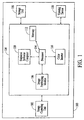
- Fig. 1 is a block diagram of an image processing system in accordance with a first embodiment of the present invention.
- Fig. 2A illustrates the Bayer pattern of color values in a mosaiced image.
- Fig. 2B illustrates the different color planes of a Bayer-patterned mosaiced image.
- Fig. 3 is a process flow diagram of the demosaicing and resizing operation of the image processing system of Fig. 1.
- Fig. 4A illustrates a partitioned 8x8 image block of a mosaiced image.
- Fig. 4B illustrates an 8×8 image block of a mosaiced image that has been vertically divided in half.
- Fig. 4C illustrates an 8x8 image block of a mosaiced image that has been horizontally divided in half.
- Fig. 4D illustrates a 4x8 image block of a mosaiced image that has been horizontally divided in half.
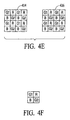
- Fig. 4E illustrates an 8x4 image block of a mosaiced image that has been vertically divided in half.
- Fig. 4F illustrates a 2x2 image block of a mosaiced image.
- Fig. 5 is a block diagram of an image processing system in accordance with a second embodiment of the present invention.
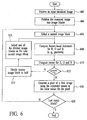
- Fig. 6 is a process flow diagram of the demosaicing and resizing operation of the image processing system of Fig. 5.
- With reference to Fig. 1, an
image processing system 100 in accordance with a first embodiment of the invention is shown. The image processing system operates to electronically capture a scene of interest as a mosaiced or raw data images and then concurrently demosaic and resize the mosaiced image, which increases the efficiency of the system and improves the quality of the resulting demosaiced and resized image. - The
image processing system 100 includes animage capturing unit 102, animage pipeline unit 104, astorage unit 106 and aviewing device 108. Theimage capturing unit 102 of the system operates to electronically capture a scene of interest in the form of a mosaiced or raw data image. The image capturing unit includes an electronic sensor and a color-filter array (CFA). The electronic sensor may be a Charge Coupled Device (CCD) sensor, a Complementary Metal Oxide Semiconductor (CMOS) sensor, or other type of photosensitive sensors. In an exemplary embodiment, the CFA includes red (R), green (G) and blue (B) filters arranged in a Bayer filter pattern. However, the CFA may include filters of other colors arranged in a different filter pattern. The CFA operates to allow only light of a particular color to be transmitted to each photosensitive element of the sensor. Thus, a digital image captured by the image capturing unit is a mosaiced image composed of single-colored pixels that are arranged in a color pattern in accordance with the filter pattern of the CFA. Consequently, each pixel of the mosaiced image has an intensity value for only a single color, e.g., R, G or B. A portion of a mosaiced image in a Bayer pattern is illustrated in Fig. 2A. - In the exemplary embodiment, since each pixel of a mosaiced image has an intensity value for only a single color, each pixel is missing intensity values for the other two colors that are needed to produce a demosaiced or color image. As illustrated in Fig. 2A, the G-colored pixels of a mosaiced image are identified as either G1 or G2, which represent two different types of G-colored pixels. Therefore, the mosaiced image of Fig. 2A can be decomposed with respect to four color components, R, G1, G2 and B, as illustrated in Fig. 2B. These decompositions of a mosaiced image will sometimes be referred herein as
G1 plane 202,G2 plane 204,R plane 206 andB plane 208. The G1 and G2 planes are collectively referred herein as the G plane. - Turning back to Fig. 1, the
image pipeline unit 104 of theimage processing system 100 is connected to theimage capturing unit 102 to receive the mosaiced images captured by the image capturing unit. The image pipeline unit operates to generate demosaiced and reduced images of the mosaiced images. The demosaiced and reduced images will sometimes be referred herein as the final images. The image pipeline unit includes animage partitioning module 106, astatistical indicator computer 108, acolor inserter 110,memory 112 and aprocessor 114. Theimage partitioning module 106, thestatistical indicator computer 108 and thecolor inserter 110 represent functional blocks and are not necessarily separate components. These components may be embodied in theimage pipeline unit 104 in any combination of software, firmware and hardware. - The
image partitioning module 106 of theimage pipeline unit 104 operates to partition an input mosaiced image from theimage capturing unit 102 into original image blocks. As an example, the image partitioning module may partition an input mosaiced image into 8x8 pixel image blocks. As described below, each original image block of the mosaiced image is converted into a single pixel to produce a final image of the input mosaiced image. Thus, the size of the final image, or the factor by which an input mosaiced image is reduced, depends on the size of the partitioned image blocks. - The
color inserter 110 of theimage pipeline unit 104 operates to compute the R, G and B color values for the converted pixel of a final image for a given original image block of an input mosaiced image. The R, G and B color values of the converted pixel are derived from the R, G1, G2 and B color values within a current image block of an input mosaiced image. The current image block may be the entire original image block of an input mosaiced image or a selected portion of the original image block. In the exemplary embodiment, the mean of R color values, the mean of G color values (both G1 and G2 color values), and the mean of B color values within a current image block are used as the R, G and B color values for the converted pixel of a final image. Thus, the color inserter is configured to compute the mean for each of the R, G and B color values of a current image block to provide R, G and B color values for the converted pixel of a final image. - The
statistical indicator computer 108 of theimage pipeline unit 104 operates to compute a statistical indicator for each of the R, G1, G2 and B color planes of a current image block to determine the statistical distribution of color values within the current image block. As an example, the statistical indicator may be the variance of intensity values for each color plane of a current image block, or other statistical indicators that can be used to measure changes of specific color intensity values within the current image block. The manner in which these statistical indicators are used by the image pipeline unit is described below. - The
processor 114 of theimage pipeline unit 104 operates to analyze the statistical indicators computed by thestatistical indicator computer 108 to determine whether the color values within a current image block are suitable to compute the R, G and B color values for a converted pixel of the final image. Specifically, the processor determines whether any of the computed statistical indicators for a current image block is greater than a predefined threshold. If so, the current image block is reduced by one half to produce a new current image block. That is, the current image block is divided by half and then one of the two halves is selected as the new current image block. The new current image block is used to compute new statistical indicators by thestatistical indicator computer 108. These new statistical indicators are then analyzed by the processor to determine whether the color values within the new current image block are suitable to compute the R, G and B color values for the converted pixel of the final image. However, if each computed statistical indicator for the current image block is not greater than the predefined threshold, the means of R, G and B color values of the current image block are embedded into the converted pixel of the final image. Embedding of color values into a pixel is defined herein as assigning the color values to the respective pixel. In the situation where the current image block includes only a single color value for the R, G1, G2 and B color planes (i.e., the current image block is a 2x2 pixel image block), the original R and B color values of the current image block are used for the converted pixel of the final image, and the average or one of the original G1 and G2 color values is used as the G color value for the converted pixel. The digital representation of the converted pixel is then temporarily stored in thememory 112 of thepipeline unit 104, which may be flash or random access memory, until all the original image blocks of the input mosaiced image have been converted to produce the final image, i.e., the demosaiced and reduced image. - The final image may be stored in the
storage unit 106 and/or displayed on theviewing device 108 of theimage processing system 100. The storage unit may be a conventional storage memory, such as DRAM. Alternatively, the storage unit may be a drive that interfaces with a removable storage medium, such as a standard computer floppy disk. The viewing device may be an LCD display or other comparable display that can display the final image. - The demosaicing and resizing operation of the
image processing system 100 is described with reference to a flow diagram of Fig. 3 and the block diagram of Fig. 1. Atstep 302, an input mosaiced image of a scene of interest is received by theimage pipeline unit 104. In the exemplary embodiment, the input mosaiced image is a Bayer patterned image captured by theimage capturing unit 102. Next, atstep 304, the mosaiced image is partitioned into image blocks. The size of the partitioned image blocks determines the factor by which the mosaiced image will be reduced. Thus, the size of the partitioned image blocks can be varied to select the size of the final image, which is the demosaiced and resized image of the input mosaiced image. However, in this description, the input mosaiced image is assumed to have been partitioned into 8x8 pixel image blocks. An exemplary 8x8 image block is illustrated in Fig. 4A. - Next, at
step 306, one of the 8x8 image blocks is selected as a current image block to generate a pixel of the final image. Atstep 308, a statistical indicator for each of the R, G1, G2 and B color values within the current image block is computed by thestatistical indicator computer 108 of theimage pipeline unit 104. In the exemplary embodiment, the statistical indicators are variances of the R, G1, G2 and B color values, and thus, the statistical indicators are described herein as variances. Initially, the current image block is the selected 8x8 image block. However, as described below, the current image block may be a portion of the selected 8x8 image block. Atstep 310, the mean of R color values, the mean of G color values (both G1 and G2 color values), and the mean of B color values within the current image block are computed by thecolor inserter 110 of theimage pipeline unit 104.Steps step 312, a determination is made whether any of the computed variances exceeds a threshold Tν , which may be empirically determined by experiments. If none of the computed variances exceeds the threshold, the process proceeds to step 318, where a pixel of the final image is generated by embedding the mean of R color values, the mean of G color values, and the mean of B color values for the current image block as the R, G and B color values into the pixel of the final image. - However, if any of the computed variances does exceed the threshold T ν , the process proceeds to step 314, where the current image block is divided in half. The current image block may be divided horizontally or vertically. The manner in which a current image block is divided is described in more detail below. Next, at
step 316, one of the divided image blocks is selected as the new current image block. The particular selection of the divided image block is not critical to the invention. After the selection of the new current image block, the process then proceeds back to step 308, where the new current image block is processed in the same manner as described above with respect to the last current image block. Thus, the computed means of a current image block are not used when there is significant variation in any color values, which may indicate that the current image block includes an edge. Consequently, the color values within such image block are not interpolated and used as the color values for the pixel of the final image, since interpolation of colors across edges may introduce undesired colors into the pixel of the final image and may degrade the final image. - In an extreme situation, the current image block may be a 2x2 pixel image block, which is the smallest possible image block that still contains color information for each of the R, G1, G2 and B color planes. In this situation, the original R and B color values of the current image block are used for the pixel of the final image, and the average or one of the original G1, G2 color values is used as the G color value for the pixel of the final image.
- After
step 318, the process proceeds to step 320, where a determination is made whether the selected 8x8 image block of the input mosaiced image is the last image block to be processed. If so, the process comes to an end. However, if the selected image block is not the last 8x8 image block of the input mosaiced image, the process proceeds back to step 306, where the next 8x8 image block of the mosaiced image is selected to be processed. - The manner in which an original 8x8 image block, such as the 8x8 image block of Fig. 4A, is divided one or more times in accordance with the invention is now described. If any of the computed variances for the 8x8 image block exceeds the threshold, the 8x8 image block may be vertically divided in half into two 4x8 image blocks 402 and 404, as illustrated in Fig. 4B. Alternatively the 8x8 image block may be horizontally divided in half into two 8x4 image blocks 406 and 408, as illustrated in Fig. 4C. Next, if the 8x8 image block was vertically divided, one of the 4x8 image blocks 402 and 404 is selected as the new current image block. If each computed variances for the selected 4x8 image block exceeds the threshold Tv , then the 4x8 image block is horizontally divided in half into two 4x4 image blocks 410 and 412, as illustrated in Fig. 4D. However, if the 8x8 image block was horizontally divided, one of the 8x4 image blocks 406 and 408 is selected as the new current image block. If each computed variances for the selected 8x4 image block exceeds the threshold Tν , then the 8x4 image block is vertically divided in half into two 4x4 image blocks 414 and 416, as illustrated in Fig. 4E. This process is continued until each computed variances for a current image block does not exceed the threshold Tv, or until the new current image block is a 2x2 image block, as illustrated in Fig. 4F. Since a 2x2 image block includes only a single value for each of the R, G1, G2 and B color planes, the image block cannot be further divided without losing some of the color values.
- In Fig. 5, an
image processing system 500 in accordance with a second embodiment of the invention is shown. Theimage processing system 500 includes most of the components of theimage processing system 100 of Fig. 1. The only difference between the twoimage processing systems statistical indicator computer 108 of theimage processing system 100 has been replaced with a feature-basedindicator computer 502 in theimage processing system 500. In contrast to thestatistical indicator computer 108, the feature-basedindicator computer 502 operates to compute a feature-based indicator, instead of a statistical indicator. In an exemplary embodiment, the feature-basedindicator computer 502 computes the gradient for each of the R color values, G color values (both G1 and G2 color values), and B color values within a current image block of an input mosaiced image. However, in other embodiments, the feature-basedindicator computer 502 may compute other feature-based indicators. - The demosaicing and resizing operation of the
image processing system 500 in accordance with the second embodiment is described with reference to a flow diagram of Fig. 6 and the block diagram of Fig. 1. Atstep 602, an input mosaiced image of a scene of interest is received by theimage pipeline unit 104. In the exemplary embodiment, the input mosaiced image is a Bayer patterned image captured by theimage capturing unit 102. Next, atstep 604, the mosaiced image is partitioned into image blocks. Although the size of the partitioned image blocks can vary, the image blocks are described herein as 8x8 image blocks. - Next, at
step 606, one of the 8x8 image blocks is selected to generate a pixel of the final image, which is the demosaiced and resized image of the input mosaiced image. Atstep 608, a feature-based indicator for each of the R, G and B color values within the current image block is computed by the feature-basedindicator computer 502 of theimage pipeline unit 104. In the exemplary embodiment, the feature-based indicators are gradients of the R, G and B color values, and thus, the feature-based indicators are described herein as gradients. At step 610, the mean of R color values, the mean of G color values (both G1 and G2 color values), and the mean of B color values within the current image block are computed by thecolor inserter 110 of theimage pipeline unit 104.Steps 608 and 610 may be executed in parallel. Next, atstep 612, a determination is made whether any of the computed gradients exceeds a threshold Tg, which may be empirically determined by experiments. If none of the computed gradients exceeds the threshold Tg, the process proceeds to step 618, where a pixel of the final image is generated by embedding the mean of R color values, the mean of G color values, and the mean of B color values for the current image block as the R, G and B color values into the pixel of the final image. - However, if any of the computed gradients do exceed the threshold Tg, the process proceeds to step 614, where the current image block is divided in half. The current image block may be divided horizontally or vertically. Next, at
step 616, one of the divided image blocks is selected as the new current image block. The process then proceeds back to step 608, where the new current image block is processed in the same manner as described above with respect to the last current image block. Thus, the computed means of a current image block are not used when there is a significant gradient with respect to any of the color values within the current image block, which indicates that the color values of the current image block are not suitable to generate interpolated color values for the pixel of the final image. Consequently, the current image block is divided to search for an image block that has color values suitable for the pixel of the final image. - After
step 618, the process proceeds to step 620, where a determination is made whether the selected 8x8 image block of the input mosaiced image is the last image block to be processed. If so, the process comes to an end. However, if the selected image block is not the last 8x8 image block of the input mosaiced image, the process proceeds back to step 606, where the next 8x8 image block of the input mosaiced image is selected to be processed. - The foregoing descriptions of specific embodiments of the invention have been presented for the purposes of illustration and description. These descriptions are not intended to be exhaustive or to limit the invention to the disclosed embodiments disclosed. Many modifications and variations are possible in light of the above teaching. The embodiments were chosen and described in order to explain the principles of the invention and its practical application, to thereby enable others skilled in the art to best utilize the invention and embodiments with various modifications as are suited to the particular use contemplated. It is intended that the scope of the invention be defined by the Claims appended hereto.
Claims (12)
- Method of demosaicing and resizing a mosaiced image, comprising:partitioning (304) the mosaiced image blocks into image blocks;receiving (306) a current image block of said mosaiced image;computing (308) an indicator of said current image block reflecting whether the color values within said current image block are suitable to compute R, G, and B color values for a converted pixel of a demosaiced image;computing (310) means ofR, G, and B color values from the current image block; generating (318) a resized image block comprising one converted pixel from said current image block of said mosaiced image if said indicator does not exceed a predefined threshold to produce a resized image of said mosaiced image, wherein said converted pixel comprises said means of R, G, and B color values such that said resized image of said mosaiced image is demosaiced; andif said indicator exceeds said predefined threshold, dividing (314) the image block to produce a smaller current image block and repeating the steps of computing and resizing the image block.
- The method of claim 1 wherein said computing of said indicator of said current image block includes computing a statistical indicator from said color data of said current image block.
- The method of claim 2 wherein said computing of said statistical indicator includes computing a variance from said color data of said current image block, said variance being used as said statistical indicator.
- The method of claim 3 wherein said computing of said variance from said color data of said current image block includes computing said variance from values within said current image block for a particular color.
- The method of claim 1 wherein said computing of said indicator of said current image block includes computing a feature-based indicator from said color data of said current image block.
- The method of claim 5 wherein said computing of said feature-based indicator includes computing a gradient from said color data of said current image block, said gradient being used as said feature-based indicator.
- The method of claim 6 wherein said computing of said gradient from said color data of said current image block includes computing said gradient from values within said current image block for a particular color.
- A system for demosaicing and resizing a mosaiced image comprising:an image processing module (100) that receives a current image block of said mosaiced image, said image processing module being configured to generate a resized image block from said current image block of said mosaiced image to produce a resized image of said mosaiced image, said image processing module including:an indicator computer (108) that is configured to compute an indicator of said current image block reflecting whether the color values within said current image block are suitable to compute R, G, and B color values for a converted pixel of a demosaiced image; anda color inserter (110) for computing means of R, G, and B color values from the current image block; andgenerating a resized image block comprising one converted pixel from said current image block of said mosaiced image if said indicator does not exceed a predefined threshold to produce a resized image of said mosaiced image, wherein said converted pixel comprises said means of R, G, and B color values such that said resized image of said mosaiced image is demosaiced; wherein said image processing module is configured to divide the image block to produce a smaller current image block and repeating the steps of computing and resizing the image block, if said indicator exceeds said predefined threshold.
- The system of claim 8 wherein said indicator computer is configured to compute a statistical indicator from said color data of said current image block.
- The system of claim 9 wherein said indicator computer is configured to compute a variance from said color data of said current image block, said variance being used as said statistical indicator.
- The system of claim 8 wherein said indicator computer is configured to compute a feature-based indicator from said color data of said current image block.
- The system of claim 11 wherein said indicator computer is configured to compute a gradient from said color data of said current image block, said gradient being used as said feature-based indicator.
Applications Claiming Priority (2)
| Application Number | Priority Date | Filing Date | Title |
|---|---|---|---|
| US09/938,438 US6989862B2 (en) | 2001-08-23 | 2001-08-23 | System and method for concurrently demosaicing and resizing raw data images |
| US938438 | 2001-08-23 |
Publications (3)
| Publication Number | Publication Date |
|---|---|
| EP1288855A2 EP1288855A2 (en) | 2003-03-05 |
| EP1288855A3 EP1288855A3 (en) | 2005-04-13 |
| EP1288855B1 true EP1288855B1 (en) | 2007-08-15 |
Family
ID=25471447
Family Applications (1)
| Application Number | Title | Priority Date | Filing Date |
|---|---|---|---|
| EP02013003A Expired - Fee Related EP1288855B1 (en) | 2001-08-23 | 2002-06-12 | System and method for concurrently demosaicing and resizing raw data images |
Country Status (4)
| Country | Link |
|---|---|
| US (1) | US6989862B2 (en) |
| EP (1) | EP1288855B1 (en) |
| JP (1) | JP2003152990A (en) |
| DE (1) | DE60221757T2 (en) |
Cited By (1)
| Publication number | Priority date | Publication date | Assignee | Title |
|---|---|---|---|---|
| CN101431683B (en) * | 2003-06-23 | 2010-12-22 | 索尼株式会社 | Image processing method and device |
Families Citing this family (38)
| Publication number | Priority date | Publication date | Assignee | Title |
|---|---|---|---|---|
| EP1308888A1 (en) * | 2001-11-06 | 2003-05-07 | STMicroelectronics S.r.l. | A method of processing digital images |
| US7158685B2 (en) * | 2002-06-28 | 2007-01-02 | Microsoft Corporation | Demosaicing graphical content |
| JP2004112738A (en) * | 2002-07-25 | 2004-04-08 | Fujitsu Ltd | Resolution conversion method and pixel data processing circuit for single-ccd color-image sensor |
| US7084906B2 (en) * | 2002-10-15 | 2006-08-01 | Eastman Kodak Company | Reducing computation time in removing color aliasing artifacts from color digital images |
| JP4497945B2 (en) * | 2003-02-04 | 2010-07-07 | キヤノン株式会社 | Imaging device |
| JP4501070B2 (en) * | 2003-10-23 | 2010-07-14 | ソニー株式会社 | Image processing apparatus, image processing method, and program |
| KR100811965B1 (en) * | 2003-12-22 | 2008-03-10 | 미쓰비시덴키 가부시키가이샤 | Pixel signal processing device and pixel signal processing method |
| US7418130B2 (en) * | 2004-04-29 | 2008-08-26 | Hewlett-Packard Development Company, L.P. | Edge-sensitive denoising and color interpolation of digital images |
| US7502063B2 (en) * | 2004-08-09 | 2009-03-10 | Aptina Imaging Corporation | Camera with scalable resolution |
| US7589779B2 (en) * | 2005-04-13 | 2009-09-15 | Seiko Epson Corporation | Imaging module, interface, and method handling multiple simultaneous data types |
| KR100689480B1 (en) * | 2005-05-09 | 2007-03-02 | 삼성전자주식회사 | Method for resizing image size in wireless terminal |
| US7668366B2 (en) | 2005-08-09 | 2010-02-23 | Seiko Epson Corporation | Mosaic image data processing |
| US7742636B2 (en) * | 2006-01-26 | 2010-06-22 | Nethra Imaging Inc. | Method and apparatus for scaling down a bayer domain image |
| US20070223057A1 (en) * | 2006-03-21 | 2007-09-27 | Sony Corporation | Method of estimating noise in spatial filtering of images |
| US7558423B2 (en) * | 2006-03-31 | 2009-07-07 | Sony Corporation | Error analysis for image interpolation and demosaicing using lattice theory |
| US20070230774A1 (en) * | 2006-03-31 | 2007-10-04 | Sony Corporation | Identifying optimal colors for calibration and color filter array design |
| US20080018753A1 (en) * | 2006-07-19 | 2008-01-24 | Chun-Ta Chiu | Method for modifying images by a way of capturing raw image data |
| US7609307B2 (en) * | 2006-09-13 | 2009-10-27 | National Chiao Tung University | Heterogeneity-projection hard-decision interpolation method for color reproduction |
| CN101796542A (en) * | 2007-07-05 | 2010-08-04 | 西门子工业公司 | Arrangement and method for procesing image data |
| US8462377B2 (en) * | 2007-07-25 | 2013-06-11 | Aptina Imaging Corporation | Method, apparatus, and system for reduction of line processing memory size used in image processing |
| US7851961B2 (en) * | 2007-09-20 | 2010-12-14 | Siemens Industry, Inc. | System and method with a rotor having parallel sided rotor bars |
| US8270713B2 (en) * | 2007-10-16 | 2012-09-18 | Aptina Imaging Corporation | Method and apparatus providing hardware-efficient demosaicing of image data |
| US8035704B2 (en) | 2008-01-03 | 2011-10-11 | Aptina Imaging Corporation | Method and apparatus for processing a digital image having defective pixels |
| US8229212B2 (en) | 2008-04-08 | 2012-07-24 | Qualcomm Incorporated | Interpolation system and method |
| US10585344B1 (en) | 2008-05-19 | 2020-03-10 | Spatial Cam Llc | Camera system with a plurality of image sensors |
| US8355042B2 (en) * | 2008-10-16 | 2013-01-15 | Spatial Cam Llc | Controller in a camera for creating a panoramic image |
| US11119396B1 (en) | 2008-05-19 | 2021-09-14 | Spatial Cam Llc | Camera system with a plurality of image sensors |
| US8164655B2 (en) | 2008-05-19 | 2012-04-24 | Spatial Cam Llc | Systems and methods for concurrently playing multiple images from a storage medium |
| US20100097444A1 (en) * | 2008-10-16 | 2010-04-22 | Peter Lablans | Camera System for Creating an Image From a Plurality of Images |
| JP5191407B2 (en) * | 2009-01-20 | 2013-05-08 | 三洋電機株式会社 | Image processing device |
| JP4873053B2 (en) * | 2009-07-27 | 2012-02-08 | セイコーエプソン株式会社 | Print control method, print control apparatus, and print control program |
| KR101725044B1 (en) * | 2010-05-27 | 2017-04-11 | 삼성전자주식회사 | Imaging display apparatus |
| US20120198386A1 (en) * | 2011-01-31 | 2012-08-02 | Nokia Corporation | Causing display of thumbnail images |
| EP2695140A1 (en) * | 2011-04-04 | 2014-02-12 | Telefonaktiebolaget LM Ericsson (PUBL) | A method and a processor for texture compression |
| US9681017B2 (en) * | 2012-11-26 | 2017-06-13 | Nokia Technologies Oy | Arrangement for image processing |
| US9280803B2 (en) | 2013-04-25 | 2016-03-08 | Mediatek Inc. | Methods of processing mosaicked images |
| KR102594038B1 (en) * | 2018-01-15 | 2023-10-26 | 에스케이하이닉스 주식회사 | Image sensing device |
| US11257184B1 (en) | 2018-02-21 | 2022-02-22 | Northrop Grumman Systems Corporation | Image scaler |
Family Cites Families (9)
| Publication number | Priority date | Publication date | Assignee | Title |
|---|---|---|---|---|
| US6046772A (en) * | 1997-07-24 | 2000-04-04 | Howell; Paul | Digital photography device and method |
| US6229578B1 (en) * | 1997-12-08 | 2001-05-08 | Intel Corporation | Edge-detection based noise removal algorithm |
| US5990950A (en) * | 1998-02-11 | 1999-11-23 | Iterated Systems, Inc. | Method and system for color filter array multifactor interpolation |
| US6236433B1 (en) | 1998-09-29 | 2001-05-22 | Intel Corporation | Scaling algorithm for efficient color representation/recovery in video |
| US7030917B2 (en) * | 1998-10-23 | 2006-04-18 | Hewlett-Packard Development Company, L.P. | Image demosaicing and enhancement system |
| US6404918B1 (en) * | 1999-04-30 | 2002-06-11 | Hewlett-Packard Company | Image demosaicing method utilizing directional smoothing |
| US20020167602A1 (en) * | 2001-03-20 | 2002-11-14 | Truong-Thao Nguyen | System and method for asymmetrically demosaicing raw data images using color discontinuity equalization |
| US6816197B2 (en) * | 2001-03-21 | 2004-11-09 | Hewlett-Packard Development Company, L.P. | Bilateral filtering in a demosaicing process |
| US6924841B2 (en) * | 2001-05-02 | 2005-08-02 | Agilent Technologies, Inc. | System and method for capturing color images that extends the dynamic range of an image sensor using first and second groups of pixels |
-
2001
- 2001-08-23 US US09/938,438 patent/US6989862B2/en not_active Expired - Fee Related
-
2002
- 2002-06-12 EP EP02013003A patent/EP1288855B1/en not_active Expired - Fee Related
- 2002-06-12 DE DE60221757T patent/DE60221757T2/en not_active Expired - Fee Related
- 2002-08-06 JP JP2002228822A patent/JP2003152990A/en not_active Ceased
Cited By (1)
| Publication number | Priority date | Publication date | Assignee | Title |
|---|---|---|---|---|
| CN101431683B (en) * | 2003-06-23 | 2010-12-22 | 索尼株式会社 | Image processing method and device |
Also Published As
| Publication number | Publication date |
|---|---|
| US6989862B2 (en) | 2006-01-24 |
| EP1288855A3 (en) | 2005-04-13 |
| US20040201721A1 (en) | 2004-10-14 |
| EP1288855A2 (en) | 2003-03-05 |
| DE60221757D1 (en) | 2007-09-27 |
| DE60221757T2 (en) | 2008-05-15 |
| JP2003152990A (en) | 2003-05-23 |
Similar Documents
| Publication | Publication Date | Title |
|---|---|---|
| EP1288855B1 (en) | System and method for concurrently demosaicing and resizing raw data images | |
| EP2089848B1 (en) | Noise reduction of panchromatic and color image | |
| US8224085B2 (en) | Noise reduced color image using panchromatic image | |
| KR101342806B1 (en) | Interpolation of panchromatic and color pixels | |
| EP2359604B1 (en) | Modifying color and panchromatic channel cfa image | |
| EP2130176B1 (en) | Edge mapping using panchromatic pixels | |
| US20080123997A1 (en) | Providing a desired resolution color image | |
| JP2004208336A (en) | Full color image adaptive interpolation arrangement using luminance gradients | |
| JP2000078597A (en) | Processor of digital color image value | |
| US20060152596A1 (en) | Noise cleaning sparsely populated color digital images | |
| JP2010537228A (en) | Pixel aspect ratio correction using panchromatic pixels | |
| JP4136255B2 (en) | Image processing apparatus and method | |
| JP2002185811A (en) | Aliasing artifact removing method for color digital image | |
| US20110032269A1 (en) | Automatically Resizing Demosaicked Full-Color Images Using Edge-Orientation Maps Formed In The Demosaicking Process | |
| US8731281B2 (en) | Wavelet transform on incomplete image data and its applications in image processing | |
| US6795586B1 (en) | Noise cleaning and interpolating sparsely populated color digital image | |
| US7558423B2 (en) | Error analysis for image interpolation and demosaicing using lattice theory | |
| Lukac | Image Resizing Solutions for Single-Sensor Digital Cameras | |
| US20070201058A1 (en) | Systems and methods for indirect image data conversion | |
| Lukac et al. | Bayer pattern based digital zooming approach | |
| KR20110035632A (en) | Method and apparatus for restoring color components in a digital camera | |
| Whitehead et al. | A low complexity method of color image demosaicing directly to YCbCr 4: 2: 0 |
Legal Events
| Date | Code | Title | Description |
|---|---|---|---|
| PUAI | Public reference made under article 153(3) epc to a published international application that has entered the european phase |
Free format text: ORIGINAL CODE: 0009012 |
|
| AK | Designated contracting states |
Kind code of ref document: A2 Designated state(s): AT BE CH CY DE DK ES FI FR GB GR IE IT LI LU MC NL PT SE TR Designated state(s): AT BE CH CY DE DK ES FI FR GB GR IE IT LI LU MC NL PT SE TR |
|
| AX | Request for extension of the european patent |
Extension state: AL LT LV MK RO SI |
|
| PUAL | Search report despatched |
Free format text: ORIGINAL CODE: 0009013 |
|
| AK | Designated contracting states |
Kind code of ref document: A3 Designated state(s): AT BE CH CY DE DK ES FI FR GB GR IE IT LI LU MC NL PT SE TR |
|
| AX | Request for extension of the european patent |
Extension state: AL LT LV MK RO SI |
|
| 17P | Request for examination filed |
Effective date: 20050513 |
|
| 17Q | First examination report despatched |
Effective date: 20050628 |
|
| AKX | Designation fees paid |
Designated state(s): DE GB |
|
| 17Q | First examination report despatched |
Effective date: 20050628 |
|
| RAP1 | Party data changed (applicant data changed or rights of an application transferred) |
Owner name: AGILENT TECHNOLOGIES, INC. |
|
| GRAP | Despatch of communication of intention to grant a patent |
Free format text: ORIGINAL CODE: EPIDOSNIGR1 |
|
| GRAS | Grant fee paid |
Free format text: ORIGINAL CODE: EPIDOSNIGR3 |
|
| GRAA | (expected) grant |
Free format text: ORIGINAL CODE: 0009210 |
|
| AK | Designated contracting states |
Kind code of ref document: B1 Designated state(s): DE GB |
|
| REG | Reference to a national code |
Ref country code: GB Ref legal event code: FG4D |
|
| REF | Corresponds to: |
Ref document number: 60221757 Country of ref document: DE Date of ref document: 20070927 Kind code of ref document: P |
|
| PLBE | No opposition filed within time limit |
Free format text: ORIGINAL CODE: 0009261 |
|
| STAA | Information on the status of an ep patent application or granted ep patent |
Free format text: STATUS: NO OPPOSITION FILED WITHIN TIME LIMIT |
|
| 26N | No opposition filed |
Effective date: 20080516 |
|
| GBPC | Gb: european patent ceased through non-payment of renewal fee |
Effective date: 20080612 |
|
| PG25 | Lapsed in a contracting state [announced via postgrant information from national office to epo] |
Ref country code: DE Free format text: LAPSE BECAUSE OF NON-PAYMENT OF DUE FEES Effective date: 20090101 |
|
| PG25 | Lapsed in a contracting state [announced via postgrant information from national office to epo] |
Ref country code: GB Free format text: LAPSE BECAUSE OF NON-PAYMENT OF DUE FEES Effective date: 20080612 |