EP1288842B1 - Adjustable focus imaging device - Google Patents
Adjustable focus imaging device Download PDFInfo
- Publication number
- EP1288842B1 EP1288842B1 EP02255185A EP02255185A EP1288842B1 EP 1288842 B1 EP1288842 B1 EP 1288842B1 EP 02255185 A EP02255185 A EP 02255185A EP 02255185 A EP02255185 A EP 02255185A EP 1288842 B1 EP1288842 B1 EP 1288842B1
- Authority
- EP
- European Patent Office
- Prior art keywords
- assembly
- media
- imaging
- lens
- imaging apparatus
- Prior art date
- Legal status (The legal status is an assumption and is not a legal conclusion. Google has not performed a legal analysis and makes no representation as to the accuracy of the status listed.)
- Expired - Lifetime
Links
Images


Classifications
-
- G—PHYSICS
- G06—COMPUTING OR CALCULATING; COUNTING
- G06K—GRAPHICAL DATA READING; PRESENTATION OF DATA; RECORD CARRIERS; HANDLING RECORD CARRIERS
- G06K7/00—Methods or arrangements for sensing record carriers, e.g. for reading patterns
- G06K7/10—Methods or arrangements for sensing record carriers, e.g. for reading patterns by electromagnetic radiation, e.g. optical sensing; by corpuscular radiation
- G06K7/10544—Methods or arrangements for sensing record carriers, e.g. for reading patterns by electromagnetic radiation, e.g. optical sensing; by corpuscular radiation by scanning of the records by radiation in the optical part of the electromagnetic spectrum
- G06K7/10792—Special measures in relation to the object to be scanned
- G06K7/10801—Multidistance reading
- G06K7/10811—Focalisation
-
- G—PHYSICS
- G02—OPTICS
- G02B—OPTICAL ELEMENTS, SYSTEMS OR APPARATUS
- G02B7/00—Mountings, adjusting means, or light-tight connections, for optical elements
- G02B7/28—Systems for automatic generation of focusing signals
Definitions
- the present invention relates generally to imaging systems and, more specifically, to an adjustable focus imaging device.
- Imaging devices are used to produce machine-readable image data (image data) that is representative of an image of an object, e.g., a page of printed text. The process of generating image data is sometimes referred to as capturing or imaging an object.
- One type of imaging device is a photoelectric imaging device.
- the phrase "photoelectric imaging device” means any device that generates image data representative of an image of an object through use of a photosensor array. Examples of photoelectric imaging devices include devices such as camcorders and digital cameras that instantaneously focus an entire image that is to be captured onto a two-dimensional photosensor array. Another example of a photoelectric imaging device is a line-focus system as described below.
- Some line-focus systems image an object by sequentially focusing narrow "scan line” portions of the image of the object onto a linear photosensor array by sweeping a scanning head over the object.
- the scanning head is an imaging device or has an imaging device located therein. Examples of such devices include computer input devices such as optical scanners, which are commonly referred to simply as “scanners”. Other examples include facsimile machines and digital copy machines.
- Imaging devices are disclosed in EP 0 757 270 A1 (Scantech B.V.) and in US patent 5,646,394 to Steinle et al.
- a line-focus system is also used in some barcode readers.
- line-focus barcode readers a narrow portion of a barcode is imaged onto a linear photosensor array. Electrical output from the photosensor array may then be analyzed to read the imaged barcode. Examples of imaging devices that are useable in conjunction with barcode readers are disclosed in United States patent 6,118,598 of Gardner, Jr. for METHOD AND APPARATUS FOR SETTING FOCUS IN AN IMAGING DEVICE and in United States patent number 6,265,705, of Gardner, Jr. for ALIGNMENT APPARATUS AND METHOD FOR AN IMAGING SYSTEM.
- US Patent 6,265,705 discloses, for example, a method of adjusting the focus of imaging apparatus, including the steps of:
- US Patent 6,265,705 also discloses, for example, a media handling device, including:
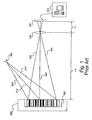
- a schematic view of a conventional line-focus system is provided for illustrative purposes.
- the line-focus system is provided with a light source 308, a plurality of light beams 310, 312, 314, a plurality of reflected light beams 320, 322, 324, a lens assembly 330, a linear photosensor array 340 and a data processing system 370.
- a use for such a line-focus system is for reading labels, perhaps a barcode 350 located on an object, such as a media storage device 360.
- the distance between the linear photosensor array 340 and the lens assembly 330 may be referred to as the image distance Li.
- light beams 310, 312, 314 are emitted from the light source 308 and are focused or directed onto the barcode 350.
- the light beams 310, 312, 314 reflect off of the barcode 350 as reflected light beams 320, 322, 324.
- Line focus systems are described in United States Patent number 6,639,203 of Kershner for CATADIOPTRIC LENS FOR A SCANNING DEVICE.
- the reflected light beams 320, 322, 324 converge at the lens assembly 330. After converging at the lens assembly 330, the reflected light beams 320, 322, 324 are focused onto the linear photosensor array 340.
- the linear photosensor array 340 may, for example, be a single dimension array of photoelements, wherein each photodetector element corresponds to a small area location on the barcode 350. These small area locations on the barcode 350 are commonly referred to as "picture elements" or "pixels.”
- the reflected light beams 320, 322, 324 travel from a corresponding pixel location on the barcode 350 to the linear photosensor array 340.
- Each photosensor pixel element in the linear photosensor array 340 (sometimes referred to simply as a "pixel") produces a data signal that is representative of the light intensity that it experiences. All of the photoelement data signals are received and processed by an appropriate data processing system 370.
- the reflected light beams 320, 322, 324 from the barcode 350 be accurately aligned with and focused onto the linear photosensor array 340 in order to accurately image an object.
- the reflected light beams 320, 322, 324 are transmitted by one or more optical components, such as the lens assembly 330 before reaching the linear photosensor array 340. Even a slight misalignment between any of these optical components and the linear photosensor array 340 will likely result in a corresponding degradation in image quality.
- WO-01/24101 discloses an optical system having a laser diode module, a primary focusing lens, and a secondary compensation lens, the secondary compensation lens being of significantly lower optical power than the primary focusing lens, the secondary compensation lens being mounted on a movable lens mount downstream of the primary focusing lens such that the primary focusing lens provides for coarse focusing of a light beam , and the secondary compensation lens provides for fine focusing of a light beam, the fine focusing being applied in place during assembly of the optical system.
- the optical components in an imaging device are mounted within an imaging device housing.
- the photosensor array is typically mounted to a circuit board, which, in turn, is mounted to the imaging device housing.
- a lens is also typically mounted within the imaging device housing. The lens serves to focus an image of an object onto the photosensor array. In order for the image to be accurately focused onto the photosensor array, and therefore the imaging device to function properly, the focus of the lens must be located at a precise position within the housing. Additionally the distance between the object and the lens assembly should remain constant. By retaining the object distance, the overall quality of the image remains constant.
- the image distance Li (Fig. 1) is generally adjusted once to focus an object located at the object distance Lo (Fig. 1). Typically, this is done by adjusting the distance between the lens and the photosensor array, i.e., the image distance Li (Fig. 1) of the optical system, until the proper focus is achieved.
- imaging devices are commonly provided having a reference surface or surfaces for locating the lens relative to the photosensor array. These reference surfaces typically allow the lens to translate in only one degree of movement, i.e., in directions toward or away from the photosensor array, but prevent the lens from being displaced in other directions.
- Imaging devices also typically include a bracket or some other retention device to lock the lens in place against the reference surface or surfaces after the focus of the imaging system has been set.
- the bracket may, for example, be secured by a screw. Accordingly, the screw may be loosened when it is desired to move the lens in order to focus the system, and then tightened to lock the lens in place when the proper focus has been achieved. This adjustment is for preliminary focusing and calibration of the system at the time of manufacturing and is typically not capable of adjustment while the system is in operation.
- Fig. 2 schematically illustrates a focus setting device 400 which may be used to set the focus of an imaging device.
- the focus setting device 400 may generally include a fixture 410 and a moveable arm 420.
- the fixture 410 is adapted to securely hold a sidewall 46 of a device, as shown.
- a moveable arm 420 may be adapted to move in the directions indicated by the arrows 422, 424 and may include a transverse portion 426 which is adapted to engage a lens assembly 260, as shown.
- the sidewall 46 may be placed into the fixture 410 of the focus setting device 400, as shown in Fig. 2.
- the lens assembly 260 may be placed onto a lens mounting area.
- a lens retention member 262 may then be placed over the lens assembly 260 and tightened.
- the resulting focus setting is a one-time setup procedure typically performed by the manufacturer.
- the present invention seeks to provide an adjustable focus imaging device.
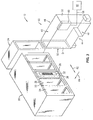
- media library device 10 may include at least one media magazine 20, at least one media play/record device 34 and at least one media handling device 40.
- Magazine 20 may include a plurality of slots 22, such as the individual slots 24, 26, 28.
- the slots 22 may be adapted to receive media storage devices, such as a media storage device 30 shown housed within the slot 28.
- Media storage device 30 may be any type of media storage device, for example, a conventional digital linear tape cartridge.
- Media storage device 30 may include a barcode label 32 affixed thereto that serves to uniquely identify the media storage device 30.
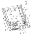
- Media handling device 40 may be in the form of a generally parallelepiped structure having a top wall 42, an oppositely disposed bottom wall 44, a left sidewall 46 and an oppositely disposed right sidewall 48, a rear wall 50 and an oppositely disposed front wall 52.
- Front wall 52 may include a generally rectangular opening 54 therein.
- An imaging device 60 which may, as an example, be a barcode reader, may be mounted to an inside surface 80 (Fig. 4) of the media handling device sidewall 46 as shown. Imaging device 60 may be attached to a computer processor 66 via a data connection 68. The imaging device 60 may serve to read barcode labels on the media storage devices, such as the barcode label 32 on the media storage device 30, in order to determine the identity of a specific media storage device.
- the media handling device 40 is moveable in a transverse direction 62 relative to the media magazine 20. In this manner, the media handling device 40 may be selectively positioned adjacent any of the slots 22 of the media magazine 20.
- a picker assembly actuator 70 (Fig. 4) located within the media handling device 40 is forwardly and reversibly moveable in a plunge direction 64 and is adapted to selectively engage a media storage device, such as the media storage device 30. In this manner, the media handling device 40 is able to move media storage devices between the media magazine 20 and one or more media playing/recording devices 34 located within the media library device 10.
- the media handling device sidewall 46 may be provided with an imaging apparatus opening 100, a sidewall hook 120, a plurality of tabs 130, 132, 134, a linear track 140 and a guide rib 150.
- the imaging apparatus opening 100 may be provided with a front portion 102 and an oppositely disposed rear portion 104.
- the imaging apparatus opening 100 may be further provided with a left portion 106 and an oppositely disposed right portion 108.
- the sidewall hook 120 may be provided at the opening front portion 102.
- the plurality of tabs 130, 132, 134 may be provided on the inner surface 80 of the media handling device sidewall 46.
- the linear track 140 may be a groove in the exemplary embodiment provided on the inner surface 80 of the media handling device sidewall 46.
- the guide rib 150 may be provided on the inner surface 80 of the media handling device sidewall 46.
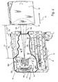
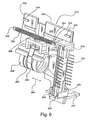
- an imaging assembly 200 may be provided with a bottom portion 202, an oppositely disposed top portion 208, a rear portion 206 and an oppositely disposed front portion 204.
- the imaging assembly 200 may be provided with a variety of features such as an imaging device slot 220, a first linear track member 240, a second linear track member 242, an imaging assembly hook 250, a lens assembly 260, a protrusion 270 and a linear photosensor array 280.
- the imaging device slot 220 may be provided with a plurality of bearing surfaces 222, 224, 226; additionally, the imaging device slot 220 may be provided near the rear portion 206 on the bottom portion 202 of the imaging assembly 200.
- the imaging device slot 220 may be provided to retain and align the linear photosensor array 280 relative to the imaging assembly. In this manner, the plurality of bearing surfaces 222, 224, 226 serve to align the linear photosensor array 280 with the lens assembly 260.
- the linear photosensor array 280 may, for example, be of the type commercially available from NEC Corporation of Japan and sold as Model No. uPD3734A.
- the imaging device slot 220 may, for example, be substantially identical to the photosensor mounting area described in U.S. Patent 6,118,598, previously referenced, except that the imaging device slot 220 is integrally formed into the imaging assembly 200. In an additional exemplary embodiment, the imaging device slot 220 may be formed in the sidewall 46, as shown in Figs. 8 and 9 and described later.
- first and second linear track members 240, 242 may be protrusions provided on the bottom portion 202 of the imaging assembly for engaging the media handling device sidewall linear track 140 (Fig. 5).
- the imaging assembly hook 250 may be provided on the bottom portion 202 of the imaging assembly 200.
- a band 262 may circumferentially capture the lens assembly 260.
- the band 262 and the lens assembly 260 may be attached to the imaging assembly 200 by a screw 266.
- the lens assembly 260 may translate in the imaging assembly 200 in an adjustment direction 268 for preliminary focusing.
- the preliminary focusing of the lens assembly 260 may occur prior to tightening the screw 266 as previously described for calibration of the device.
- the lens assembly 260 may be fixed at a predetermined position with respect to the image assembly 200.
- the protrusion 270 may be provided on the top portion 208 of the imaging assembly 200.
- a spring 300 may be provided with a first end portion 302 and an oppositely disposed second end portion 304.
- the end portions 302, 304 are preferably formed into loops for readily attaching to hooks, such as the sidewall hook 120 and the imaging assembly hook 250.
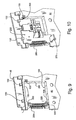
- assembling the imaging assembly 200 in the sidewall 46 may entail slideably attaching the imaging assembly 200 to the media handling device sidewall 46 in the plunger direction 64.
- the imaging assembly 200 slides under the sidewall tabs 130 and 134.
- the tab 132 captures the imaging assembly 200.
- the second linear track member 242 contacts the sidewall linear track 140.
- the imaging assembly 200 slides to a first position when the front portion 204 of the imaging assembly 200 contacts the front portion 102 of the left sidewall 46 as shown in Fig. 7.
- the spring 300 is attached to the left sidewall 46 and the imaging assembly 200. Referring to Fig. 6, the attachment of the spring 300 may begin by placing the second end portion 304 of the spring 300 over the imaging assembly hook 250. Furthermore, the spring 300 is attached to the left sidewall 46 (Fig. 5) by placing the first end portion 302 over the sidewall hook 120 (Fig. 5).
- the spring 300 urges the imaging assembly 200 to one end of a range of travel.
- the range of travel may, for example, be 6 millimeters. The previous dimension is given for exemplary purposes and is considered to be a matter of design preference. As such, the range of travel may vary depending on the travel that is required for a particular application.
- the front portion 204 is urged against the front portion 102 and held in the first position by a force exerted by the spring 300.
- the imaging assembly 200 is located in the first position, without being engaged with the picker assembly actuator 70.
- an orientation distance Od between the media handling device 40 and the object being imaged can vary.
- This variation in the orientation distance may, for example, be caused by the fact that different types of media play/record devices (such as the media play/record device 34, Fig. 3) may be used in conjunction with the media library device 10.
- the different types of media play/record devices may position the media storage device 30 at a slightly different orientation distance Od from the media handling device 40.
- some media play/record devices may position the media storage device 30 at the orientation distance from the imaging device 60 that is different from the orientation distance at which the media handling device 40 was calibrated as previously described.
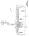
- the imaging assembly 200 is capable of movement in the plunge direction 64 relative to the sidewall 46. Accordingly, variations in the orientation distance Od (Fig. 4) of an object being imaged may be compensated for by moving the imaging assembly 200 in the positive or negative plunge direction 64. This movement of the imaging assembly 200, in turn serves to restore the object distance Lo. The restoration of the object distance Lo allows focusing of the image on the linear photosensor array 280.
- the picker assembly actuator 70 may be used to change the location of the imaging assembly 200.
- the picker assembly actuator 70 may be provided with a gear assembly 72 that interfaces with a toothed rack (not shown).
- the gear assembly 72 rotates. Since the gear assembly 72 is in operational contact with the toothed rack, rotation of the gear assembly 72 causes movement of the picker assembly actuator 70.
- a contact portion 74 on the picker assembly actuator 70 contacts the protrusion 270.
- the picker assembly actuator 70 moves in the negative plunge direction 64, the protrusion 270 and all elements operatively attached thereto move.
- moving the picker assembly actuator 70 causes movement of the imaging assembly 200 if the imaging assembly 200 is in contact with the picker assembly actuator contact portion 74.
- the image projected on the linear photosensor array 280 becomes focused at a predetermined position when the object distance Lo is restored.
- the predetermined position may be where the barcode label 32 was located during the calibration as discussed earlier.
- Fig. 8 shows the imaging assembly 200 in a second position, wherein the picker assembly actuator 70 has displaced the imaging assembly 200. At this second position, the imaging assembly 200 has been displaced by a controlled distance Cd.
- the quality of the image may be monitored by a number of methods including software-based analysis.
- the computer processor 66 may have an imbedded software algorithm that may monitor the focus of the image on the linear photosensor array 280.
- the imaging assembly 200 reads the barcode label 32 with the linear photosensor array 280 and generates data that represents the barcode label 32.
- the data is sent in electronic format to the computer processor 66.
- the algorithm may evaluate the quality of the resulting data to determine if the image was readable.
- One exemplary method for determining if the image quality is sufficient may be that the algorithm evaluates the resulting signal generated by the linear photosensor array 280.
- the voltages created for white and black portions of the barcode label 32 may be compared to ensure that the voltage levels are sufficient.
- the computer processor 66 may adjust the focus.
- the computer processor 66 may direct the picker assembly actuator 70 to move into contact with the imaging assembly protrusion 270. After contacting the imaging assembly protrusion 270, the picker assembly actuator 70 moves the imaging assembly 200 to a location and stops. After stopping, the computer processor 66 takes another image reading of the image on the linear photosensor array 280.
- the computer processor 66 evaluates the quality of the data to determine if the barcode label 32 was successfully read. In the event that the barcode label 32 was successfully read, the media storage device 30 was identified and focusing may terminate. However, if the data is determined to be compromised, then the computer processor 66 may adjust the focus again. This process of moving the imaging assembly 200 and evaluating the resulting data generated by the linear photosensor array 280 continues until the barcode label 32 is focused and identified. With the preceding example of how the movement of the imaging assembly 200 may be controlled, it can be appreciated that the imaging assembly 200 may be moved a required distance in order to obtain an adequate reading of the object such as barcode label 32. A description of typical operation sequence will now be provided. Referring to Fig. 3, the media storage device 30 located in the magazine slot 28 may contain data that needs to be retrieved. The computer processor 66 communicates with the media handling device 40 to locate the media storage device 30 and deliver it to the media play/record device 34.
- the media handling device 40 moves in the transverse direction 62 until it is aligned with the media storage device 30.
- the imaging device 60 reads the barcode label 32 located on the media storage device 30. If the barcode label 32 matches the required data, then the picker assembly actuator 70 advances in the plunge direction 64.
- the picker assembly actuator 70 advances through the opening 54 and captures the media storage device 30. Then the picker assembly actuator 70 retreats with the captured media storage device 30 into the media handling device 40 in the negative plunge direction 64.
- the media handling device 40 moves in the transverse direction 62 to the media play/record device 34.
- the picker assembly actuator 70 moves in the plunge direction 64.
- the movement of the picker assembly actuator 70 causes the media storage device 30 to egress from the media handling device 40 through the opening 54 and into the media play/record device 34. While the media storage device 30 is in the media play/record device 34, the media play/record device 34 locates and reads the required data. While the media play/record device 34 is reading the data, the media handling device 40 may be moving inside the media library device 10 performing similar locate, move and place operations.
- the computer processor 66 may direct the media handling device 40 to return to the media play/record device 34 to remove the media storage device 30.
- the media storage device 30 is identified by reading the barcode label 32. Referring to Fig. 4, reading the barcode label 32 on the media storage device 30 is accomplished by emitting light from the light source 308 (Fig. 1). Individual light beams such as light beams 310, 312, 314 (Fig. 1) emitted from the light source 308 and reflect off of the barcode label 32 as reflected light beams such as reflected light beams 320, 322, 324. The reflected light beams travel through the lens assembly 260 and are imaged onto the linear photosensor array 280.
- the computer processor 66 monitors the image of the linear photosensor array 280. If the image is not focused and the data is not adequately obtained, the imaging assembly 200 is moved. In the exemplary embodiment as shown, the imaging assembly 200 is moved by the picker assembly actuator 70 as previously described. The imaging assembly 200 is moved until the quality of the image is optimized. The process of optimizing the image quality is performed as previously described; however, in summary, a software algorithm integrated in the computer processor 66 monitors the quality of the image and accordingly focuses. After a suitable image is obtained, the picker assembly actuator 70 may advance to capture the media storage device 30. After capturing the media storage device 30, the media storage device 30 is removed from the media play/record device 34. The media storage device 30 is then returned to the media magazine 20 for storage until it is needed again. This operation and sequence may be repeated by the media library device 10 for various reading and writing operations as required.
- the imaging device 60 may also be directed to a fixed linear photosensor array in an additional exemplary embodiment.
- the image device slot 220 may be an integrated feature on the media handling device sidewall 46.
- the imaging assembly 200 is substantially similar as previously described, however the imaging device slot 220 is omitted.
- the actuation of the picker assembly actuator 70 against the protrusion 270 causes movement of the imaging assembly 200 and all features operatively associated thereto. Since the lens assembly 260 is operatively associated with the imaging assembly 200, the lens assembly 260 moves. The movement of the lens assembly 260 in this exemplary embodiment results in a scaling of the image size projected on the linear photosensor array 280.
- the scaled image may be larger or smaller than the image obtained during calibration, which may be beneficial in certain applications.
- the exemplary embodiment as shown in Figs. 9 and 10 results in a focused barcode image capable of being converted to machine-readable image data.
- the spring 300 is an extension spring capable of applying force to objects to which it is attached.
- Other examples of members that may be used to apply force include elastic bands, pneumatic cylinders, hydraulic cylinders, bumpers, or their equivalents.
- any number of linear displacement mechanisms may be provided to move the imaging assembly 200. It is preferable, however, that the picker assembly actuator 70 be used to move the imaging assembly 200 because the picker assembly actuator 70 is an existing component in many media handling devices 40. Additionally, there are space constraints within the media handling device 40 and additional components may increase the exterior dimensions of the media handling device 40. Since the picker assembly actuator 70 is an existing component, the overall size of the media handling device 40 remains the same. Substitutes for the picker assembly actuator 70 have been contemplated, including: providing elements such as a threaded rod and a nut, a solenoid, pneumatic bellows, linear actuators, rotary actuators, or their equivalents.
- an exemplary process of controlling movement of the imaging assembly 200 may be accomplished with a software-based algorithm.
- Other processes of controlling the quality of the image have been contemplated. Two of these processes will be presented herein for exemplary purposes, one process being a database process and the other being a plurality-of-locations process.
- the database process may be an integrated feature in the computer processor 66, Fig. 3.
- the integrated database contains information as to what position the barcode label 32 is located at for a particular play/record device 34 or media magazine 20.
- the computer processor 66 Based on the particular location of the barcode label 32, the computer processor 66 'looks up' the corresponding position of the imaging assembly 200 that results in a focused image on the linear photosensor array 280.
- the computer processor 66 directs the picker assembly actuator 70 to move the imaging assembly 200 to the position that was 'looked up' whereat the image on the linear photosensor array 280 is focused.
- data may be obtained from the linear photosensor array by the computer processor 66.
- Another alternative method for obtaining a quality image may be a plurality-of-locations process.
- the plurality of locations may correspond to various locations of the barcode label 32 on media storage devices 30 located in various play/record devices 34 or media magazines 20. For example, if there are three different media play/record devices 34 and one type of media magazine 20, there would be four locations of the barcode label 32 (assuming that each device positions the media storage device 30 and the barcode label 32 attached thereto at unique locations).
- the computer processor may direct the picker assembly actuator 70 to move the imaging assembly 200 to one of the four locations and capture an image of the barcode label 32. The process of moving the imaging assembly 200 to the remaining three locations and capturing three additional images may occur.
- the computer processor 66 evaluates the four images captured by the linear photosensor array 280 and utilizes the best image to identify the media storage device 30. With this plurality-of-locations process, the process may be terminated if a focused image is found in one of the earlier readings, rather than cycling through all four locations.
- the computer processor 66 may be provided with a database used for optimizing the speed of the system.
- the database may be used to store the locations at which optimal focusing of objects, such as barcode label 32, occurred for the various components, such as media storage device 30, housed within the media library device 10.
- the system may move the imaging assembly 200 to the focused position prior to reading the barcode label 32. This predetermined movement allows for efficient reading of barcode labels 32, thereby improving overall data recovery speeds.
- the adjustable focus imaging device is capable of reading images such as the barcode 32 on objects such as the media storage device 30. This reading can be made even though the location of the media storage device 30 may vary.
- the device utilizes an existing member such as the picker assembly actuator 70 for moving the imaging assembly 200, although other variations have been contemplated and disclosed herein.
- the overall size and manufacturing cost of the adjustable focus imaging device remains substantially similar to the prior art device.
Landscapes
- Physics & Mathematics (AREA)
- Engineering & Computer Science (AREA)
- Electromagnetism (AREA)
- General Physics & Mathematics (AREA)
- Artificial Intelligence (AREA)
- Toxicology (AREA)
- General Health & Medical Sciences (AREA)
- Computer Vision & Pattern Recognition (AREA)
- Health & Medical Sciences (AREA)
- Theoretical Computer Science (AREA)
- Optics & Photonics (AREA)
- Automatic Tape Cassette Changers (AREA)
- Studio Devices (AREA)
- Stereoscopic And Panoramic Photography (AREA)
- Focusing (AREA)
Applications Claiming Priority (2)
| Application Number | Priority Date | Filing Date | Title |
|---|---|---|---|
| US940959 | 2001-08-27 | ||
| US09/940,959 US6664525B2 (en) | 2001-08-27 | 2001-08-27 | Adjustable focus imaging device |
Publications (3)
| Publication Number | Publication Date |
|---|---|
| EP1288842A2 EP1288842A2 (en) | 2003-03-05 |
| EP1288842A3 EP1288842A3 (en) | 2003-12-03 |
| EP1288842B1 true EP1288842B1 (en) | 2007-05-30 |
Family
ID=25475711
Family Applications (1)
| Application Number | Title | Priority Date | Filing Date |
|---|---|---|---|
| EP02255185A Expired - Lifetime EP1288842B1 (en) | 2001-08-27 | 2002-07-25 | Adjustable focus imaging device |
Country Status (4)
| Country | Link |
|---|---|
| US (1) | US6664525B2 (enExample) |
| EP (1) | EP1288842B1 (enExample) |
| JP (1) | JP2003115027A (enExample) |
| DE (1) | DE60220348T2 (enExample) |
Families Citing this family (2)
| Publication number | Priority date | Publication date | Assignee | Title |
|---|---|---|---|---|
| US7004392B2 (en) * | 2001-12-19 | 2006-02-28 | Storage Technology Corporation | Barcode single laser scanner targeting |
| EP3281018B1 (en) * | 2015-04-07 | 2023-06-07 | Gen-Probe Incorporated | Systems and methods for reading machine-readable labels on sample receptacles |
Family Cites Families (11)
| Publication number | Priority date | Publication date | Assignee | Title |
|---|---|---|---|---|
| US5296970A (en) * | 1992-03-30 | 1994-03-22 | Fuji Photo Optical Co., Ltd | Zoom lens system |
| US5646394A (en) | 1995-03-16 | 1997-07-08 | Hewlett-Packard Company | Imaging device with beam steering capability |
| NL1000923C2 (nl) * | 1995-08-03 | 1997-02-04 | Scantech Bv | Autofocusseerinrichting. |
| US5729464A (en) * | 1995-09-29 | 1998-03-17 | International Business Machines Corporation | Media identification in an automated data library |
| JPH116951A (ja) * | 1997-06-16 | 1999-01-12 | Canon Inc | レンズ装置または光学機器 |
| US6147343A (en) | 1998-07-23 | 2000-11-14 | Hewlett-Packard Company | Photoelectric imaging method and apparatus |
| US6331714B1 (en) * | 1999-04-13 | 2001-12-18 | Hewlett-Packard Company | Guidance system and method for an automated media exchanger |
| US6265705B1 (en) * | 1999-04-13 | 2001-07-24 | Hewlett-Packard Company | Alignment apparatus and method for an imaging system |
| US6118598A (en) * | 1999-04-13 | 2000-09-12 | Hewlett-Packard Company | Method and apparatus for setting focus in an imaging device |
| US6194697B1 (en) * | 1999-04-13 | 2001-02-27 | Hewlett-Packard Company | Calibration system for an imaging apparatus and method |
| WO2001024101A1 (en) * | 1999-09-27 | 2001-04-05 | Psc Scanning, Inc. | Coarse and fine focus mechanism for a data reader |
-
2001
- 2001-08-27 US US09/940,959 patent/US6664525B2/en not_active Expired - Fee Related
-
2002
- 2002-07-25 DE DE60220348T patent/DE60220348T2/de not_active Expired - Fee Related
- 2002-07-25 EP EP02255185A patent/EP1288842B1/en not_active Expired - Lifetime
- 2002-08-21 JP JP2002239992A patent/JP2003115027A/ja active Pending
Non-Patent Citations (1)
| Title |
|---|
| None * |
Also Published As
| Publication number | Publication date |
|---|---|
| US20030038256A1 (en) | 2003-02-27 |
| DE60220348T2 (de) | 2008-04-10 |
| US6664525B2 (en) | 2003-12-16 |
| EP1288842A2 (en) | 2003-03-05 |
| JP2003115027A (ja) | 2003-04-18 |
| DE60220348D1 (de) | 2007-07-12 |
| EP1288842A3 (en) | 2003-12-03 |
Similar Documents
| Publication | Publication Date | Title |
|---|---|---|
| US20110274419A1 (en) | Lens barrel, camera and lens barrel adjustment device | |
| US6897432B2 (en) | Imaging apparatus having discontinuous lens reference surfaces and method of assembling the imaging apparatus | |
| EP0508709B1 (en) | Contact-type image sensor assembly | |
| JP2001228418A (ja) | マルチビーム光源ユニットの調整方法、その調整装置、その光源ユニットの組立方法及びそれを用いる画像形成装置 | |
| US6438448B1 (en) | Self aligning robotic arm calibration apparatus | |
| US5394205A (en) | Image reading apparatus | |
| JP4366967B2 (ja) | 光走査装置及び画像形成装置 | |
| EP1045268B1 (en) | Setting focus in an imaging system | |
| EP1288842B1 (en) | Adjustable focus imaging device | |
| US20060077479A1 (en) | Image reading device and method of scaling up or down image to be read | |
| US6265705B1 (en) | Alignment apparatus and method for an imaging system | |
| CA2316433A1 (en) | Apparatus and method for edge detection | |
| US6163333A (en) | Multi-beam scanning optical apparatus | |
| US7847983B2 (en) | Image reading apparatus | |
| EP1089546B1 (en) | Position sensing device having a movable photosensing element | |
| JP2003255248A (ja) | マルチビーム光源装置及びそれを用いた走査光学装置 | |
| US7826108B2 (en) | Scanning apparatus for preventing defocus aberration | |
| US6464416B1 (en) | Apparatus having carriage scanning mechanism, and recording apparatus, information recording/reproducing apparatus, information recording apparatus, information reproduction apparatus, information reading apparatus and information erasing apparatus, each provided with apparatus having carriage scanning mechanism | |
| US7106480B2 (en) | Film scanning device | |
| US5488225A (en) | Rotary scanner and light beam scanning system having a specified relationship between the facets of the scanning mirror and the commuter segments of the motor | |
| EP1251393B1 (en) | Slide mount carrier unit and film scanner | |
| JP2000013570A (ja) | 書き込みユニットの調整方法及び調整装置 | |
| JPH0583861U (ja) | 光学読取装置 | |
| JPH11202235A (ja) | 光走査装置 | |
| JPH04223662A (ja) | 画像読取り装置 |
Legal Events
| Date | Code | Title | Description |
|---|---|---|---|
| PUAI | Public reference made under article 153(3) epc to a published international application that has entered the european phase |
Free format text: ORIGINAL CODE: 0009012 |
|
| AK | Designated contracting states |
Kind code of ref document: A2 Designated state(s): AT BE BG CH CY CZ DE DK EE ES FI FR GB GR IE IT LI LU MC NL PT SE SK TR |
|
| AX | Request for extension of the european patent |
Extension state: AL LT LV MK RO SI |
|
| PUAL | Search report despatched |
Free format text: ORIGINAL CODE: 0009013 |
|
| AK | Designated contracting states |
Kind code of ref document: A3 Designated state(s): AT BE BG CH CY CZ DE DK EE ES FI FR GB GR IE IT LI LU MC NL PT SE SK TR |
|
| AX | Request for extension of the european patent |
Extension state: AL LT LV MK RO SI |
|
| RIC1 | Information provided on ipc code assigned before grant |
Ipc: 7G 11B 17/22 B Ipc: 7G 02B 17/08 B Ipc: 7G 06K 7/10 A Ipc: 7G 03B 17/14 B Ipc: 7H 01J 3/14 B Ipc: 7G 02B 7/00 B Ipc: 7H 04N 5/232 B Ipc: 7G 02B 3/00 B |
|
| 17P | Request for examination filed |
Effective date: 20040517 |
|
| 17Q | First examination report despatched |
Effective date: 20040614 |
|
| AKX | Designation fees paid |
Designated state(s): DE FR GB |
|
| GRAP | Despatch of communication of intention to grant a patent |
Free format text: ORIGINAL CODE: EPIDOSNIGR1 |
|
| GRAS | Grant fee paid |
Free format text: ORIGINAL CODE: EPIDOSNIGR3 |
|
| GRAA | (expected) grant |
Free format text: ORIGINAL CODE: 0009210 |
|
| AK | Designated contracting states |
Kind code of ref document: B1 Designated state(s): DE FR GB |
|
| REG | Reference to a national code |
Ref country code: GB Ref legal event code: FG4D |
|
| REF | Corresponds to: |
Ref document number: 60220348 Country of ref document: DE Date of ref document: 20070712 Kind code of ref document: P |
|
| PLBE | No opposition filed within time limit |
Free format text: ORIGINAL CODE: 0009261 |
|
| STAA | Information on the status of an ep patent application or granted ep patent |
Free format text: STATUS: NO OPPOSITION FILED WITHIN TIME LIMIT |
|
| PGFP | Annual fee paid to national office [announced via postgrant information from national office to epo] |
Ref country code: FR Payment date: 20070717 Year of fee payment: 6 |
|
| 26N | No opposition filed |
Effective date: 20080303 |
|
| PG25 | Lapsed in a contracting state [announced via postgrant information from national office to epo] |
Ref country code: FR Free format text: LAPSE BECAUSE OF FAILURE TO SUBMIT A TRANSLATION OF THE DESCRIPTION OR TO PAY THE FEE WITHIN THE PRESCRIBED TIME-LIMIT Effective date: 20080125 |
|
| PGFP | Annual fee paid to national office [announced via postgrant information from national office to epo] |
Ref country code: DE Payment date: 20090729 Year of fee payment: 8 Ref country code: GB Payment date: 20090727 Year of fee payment: 8 |
|
| GBPC | Gb: european patent ceased through non-payment of renewal fee |
Effective date: 20100725 |
|
| PG25 | Lapsed in a contracting state [announced via postgrant information from national office to epo] |
Ref country code: DE Free format text: LAPSE BECAUSE OF NON-PAYMENT OF DUE FEES Effective date: 20110201 |
|
| REG | Reference to a national code |
Ref country code: DE Ref legal event code: R119 Ref document number: 60220348 Country of ref document: DE Effective date: 20110201 |
|
| PG25 | Lapsed in a contracting state [announced via postgrant information from national office to epo] |
Ref country code: GB Free format text: LAPSE BECAUSE OF NON-PAYMENT OF DUE FEES Effective date: 20100725 |