EP1288770B1 - Portable information appliance - Google Patents
Portable information appliance Download PDFInfo
- Publication number
- EP1288770B1 EP1288770B1 EP01936863A EP01936863A EP1288770B1 EP 1288770 B1 EP1288770 B1 EP 1288770B1 EP 01936863 A EP01936863 A EP 01936863A EP 01936863 A EP01936863 A EP 01936863A EP 1288770 B1 EP1288770 B1 EP 1288770B1
- Authority
- EP
- European Patent Office
- Prior art keywords
- thermal insulator
- portable information
- information device
- vacuum thermal
- set forth
- Prior art date
- Legal status (The legal status is an assumption and is not a legal conclusion. Google has not performed a legal analysis and makes no representation as to the accuracy of the status listed.)
- Expired - Lifetime
Links
Images




Classifications
-
- G—PHYSICS
- G06—COMPUTING OR CALCULATING; COUNTING
- G06F—ELECTRIC DIGITAL DATA PROCESSING
- G06F1/00—Details not covered by groups G06F3/00 - G06F13/00 and G06F21/00
- G06F1/16—Constructional details or arrangements
- G06F1/20—Cooling means
- G06F1/203—Cooling means for portable computers, e.g. for laptops
-
- A—HUMAN NECESSITIES
- A01—AGRICULTURE; FORESTRY; ANIMAL HUSBANDRY; HUNTING; TRAPPING; FISHING
- A01N—PRESERVATION OF BODIES OF HUMANS OR ANIMALS OR PLANTS OR PARTS THEREOF; BIOCIDES, e.g. AS DISINFECTANTS, AS PESTICIDES OR AS HERBICIDES; PEST REPELLANTS OR ATTRACTANTS; PLANT GROWTH REGULATORS
- A01N25/00—Biocides, pest repellants or attractants, or plant growth regulators, characterised by their forms, or by their non-active ingredients or by their methods of application, e.g. seed treatment or sequential application; Substances for reducing the noxious effect of the active ingredients to organisms other than pests
- A01N25/08—Biocides, pest repellants or attractants, or plant growth regulators, characterised by their forms, or by their non-active ingredients or by their methods of application, e.g. seed treatment or sequential application; Substances for reducing the noxious effect of the active ingredients to organisms other than pests containing solids as carriers or diluents
- A01N25/10—Macromolecular compounds
-
- A—HUMAN NECESSITIES
- A01—AGRICULTURE; FORESTRY; ANIMAL HUSBANDRY; HUNTING; TRAPPING; FISHING
- A01N—PRESERVATION OF BODIES OF HUMANS OR ANIMALS OR PLANTS OR PARTS THEREOF; BIOCIDES, e.g. AS DISINFECTANTS, AS PESTICIDES OR AS HERBICIDES; PEST REPELLANTS OR ATTRACTANTS; PLANT GROWTH REGULATORS
- A01N43/00—Biocides, pest repellants or attractants, or plant growth regulators containing heterocyclic compounds
- A01N43/34—Biocides, pest repellants or attractants, or plant growth regulators containing heterocyclic compounds having rings with one nitrogen atom as the only ring hetero atom
- A01N43/36—Biocides, pest repellants or attractants, or plant growth regulators containing heterocyclic compounds having rings with one nitrogen atom as the only ring hetero atom five-membered rings
-
- A—HUMAN NECESSITIES
- A01—AGRICULTURE; FORESTRY; ANIMAL HUSBANDRY; HUNTING; TRAPPING; FISHING
- A01N—PRESERVATION OF BODIES OF HUMANS OR ANIMALS OR PLANTS OR PARTS THEREOF; BIOCIDES, e.g. AS DISINFECTANTS, AS PESTICIDES OR AS HERBICIDES; PEST REPELLANTS OR ATTRACTANTS; PLANT GROWTH REGULATORS
- A01N51/00—Biocides, pest repellants or attractants, or plant growth regulators containing organic compounds having the sequences of atoms O—N—S, X—O—S, N—N—S, O—N—N or O-halogen, regardless of the number of bonds each atom has and with no atom of these sequences forming part of a heterocyclic ring
Definitions
- the present invention relates to a portable information device such as a notebook type computer, and more particularly to a portable information device that avoids heat generated in it from being transferred to a user, and prevents malfunction.
- a portable information device such as a notebook type computer of recent years
- a surface of a device enclosure When heat generated within a portable information device such as a notebook type computer of recent years is transferred to a surface of a device enclosure, and raises temperature of the surface of the device enclosure, the heat on a portion of the enclosure surface that stays in contact for a long time with a body of a user of the device gives an uncomfortable feeling to the user.
- Sources of the heat within the computer are mainly a CPU and power supply, and a surface temperature of the CPU, in particular, reaches such a temperature that exceeds approx. 100°C.
- thermal insulators are used to block heat between a heating component in the device and the device enclosure.
- a notebook type computer of a structure including a thermal insulator for isolating between a heating component in the device and a device enclosure, a heat sink disposed to a back surface of a display unit, a heat pipe for conducting heat generated in the device to the heat sink, and an air vent, as disclosed in Japanese Patent Laid-open Publication, No. 11-202978 .
- Temperature rise on the enclosure surface can be reduced to some extent by using the technique taught in the publication, 11-202978 .
- thermal insulator it is necessary to increase a thickness of the thermal insulator in order to attain an effect of reducing an amount of heat transferred to the surface of the device enclosure, because the effect is small if thermal insulation property of the thermal insulator is low.
- the thermal insulators since low-profiling and weight-reduction are desired in these days for notebook type computers, it is also necessary for the thermal insulators to be small and light weight.
- the heat generated within a device may cause an adverse effect to external expansion terminals such as a random-access memory (RAM) card and a local area network (LAN) card, and leads them into malfunction.
- RAM random-access memory
- LAN local area network
- thermal insulators fibrous body such as glass wool, and foam body such as polyurethane foam and the like are used. In order to improve insulating properties of these thermal insulators, however, it is necessary to increase their thicknesses. The thicknesses are therefore not suitable to a need to save or use spaces efficiently due to limitation in the spaces available for installation of the thermal insulators.
- a vacuum thermal insulator including a core member, which maintains a space, and an enveloping member, which shields the space from the open air is available.
- Pulverulent material, fibrous material, continuously-formed foam body, and the like are used generally as the core member.
- even more efficient vacuum thermal insulators are now in demand.
- Japanese Patent Laid-open Publication, No. 60-33479 teaches a vacuum thermal insulator characterized by uniformly-distributed pulverized carbon into pearlite powder for improving efficiency of the core member. It also discloses the vacuum thermal insulator including the pulverized carbon consisting of carbon black. The thermal insulation property can be improved by 20% under the optimum condition by the uniformly distributing carbon black into the pearlite.
- Japanese Patent Laid-open Publication, No. 61-36595 teaches a vacuum thermal insulator characterized by uniformly-distributed carbon powder in various pulverulent substances.
- carbon black is distributed uniformly into silica having 100nm in particulate diameter, and obtains an improvement of 20 % in the thermal insulation property under the optimum condition.
- Japanese Patent Examined Publication, No. 08-20032 discloses a vacuum thermal insulator which uses fine powder produced from fumes generated in the production of ferrosilicon. It also discloses the vacuum thermal insulator in which the fine powder contains at least carbon in an amount of 1 wt% or more. This thermal insulator exhibits an improvement of 23 % in the thermal insulation property.
- the pearlite in Patent Publication 60-33479 the silica having particulate diameter of 100nm in Patent Publication 61-36595 , and the fumes generated in the production of ferrosilicon in Patent Publication 8-20032 , all containing pulverized carbon or other forms of carbon
- the pearlite, the silica having particulate diameter of 100nm, and the fumes generated in the production of ferrosilicon, as used for the base material do not exhibit any distinguishable effect as the core member of the vacuum thermal insulator. Therefore, they do not improve the thermal insulation property substantially, and their effects of improvement are only up to about 20% when compared with other vacuum thermal insulators, even though these materials are intended for a large improvement by containing pulverized carbon and the other forms of carbon.
- the carbon black exhales gas over time, since it generally is a sooty product obtained through imperfect combustion of oil content and it contains organic gas as impurity. Thus, it has had a problem that an increase in an internal pressure of the vacuum thermal insulator causes degradation of the thermal insulation property.
- reaction-active radicals such as carbonyl group present in the carbon black at ends of their molecular structures react with moisture in air so as to also produce gas over time, thereby increasing the internal pressure of the vacuum thermal insulator and degrading the thermal insulation property in the similar manner.
- Porous bodies are generally used as the core member, which can be classified broadly into one of continuous foam, fibrous group, and pulverulent group.
- silica powder is often used as one of the pulverulent group vacuum insulator materials.
- Vacuum thermal insulator that uses silica powder is superior in the thermal insulation property over a long duration of time, although it falls behind the fibrous group material in the initial thermal insulation property.
- Japanese Patent Examined Publication, No. 04-46348 discloses a vacuum thermal insulator having a compact body made of wet silica mixed and compressed with fiber reinforcement.
- Japanese Patent Examined Publication, No. 05-66341 discloses a vacuum thermal insulator including a compact body made of dry silica, wet silica and fiber reinforcement, which are mixed, distributed, and compressed.
- a compact body is formed in which the dry silica and the wet silica supplement each other by their respective features of low coefficient of thermal conductivity and easiness of press-working, with addition of mixing fiber reinforcement into it.
- the formed body is so brittle that it crumbles easily when being picked up with a hand. In addition, it also raises heavy powdery dust thus deteriorating workability and ease of handling. If it is formed into a cylindrical shape, for example, it crumbles so quickly. Also, since lacking flexibility, the body has a limitation in the field of applications.
- the body is not easily formed, and is brittle because it contains the wet silica mixed to it. In addition, it raises heavy powdery dust, and lacks flexibility.
- Document JP 11 202978 discloses a notebook-sized computer having an aluminium board for ground laid on the base part of the computer case.
- the aluminium board and the case is surrounded with a heat insulator.
- the heat is conducted through a heat pipe to a radiation board and radiated into air.
- the radiation board is arranged inside the display part.
- a portable information device such as a notebook type computer having a highly efficient thermal insulator blocks a transfer of heat between an internal heating component and a device enclosure without causing impediment to a low-profile design.
- This information device suppresses temperature rise on a surface of the device, so as not to give uncomfortable feeling to a user.
- the information device is also provided with an efficient thermal insulator for blocking a transfer of heat between the internal heating component and a built-in mounting case of an external expansion unit, thereby suppressing temperature rise of the external expansion unit and preventing malfunction of the unit.
- Fig. 1 shows a notebook type computer 101 according to the first exemplary embodiment.
- the computer 101 includes a vacuum thermal insulator 105 separating between heating component 103 on an internal main board 102 and a bottom of a device enclosure 104, and a heat sink 106.
- This computer alleviates temperature rise on a surface of the device, and prevents heat from being transferred to a user, since it can effectively block transfer of the heat to the bottom surface.
- Fig. 2 shows a notebook type computer 101 according to the second exemplary embodiment.
- the computer 101 includes a vacuum thermal insulator 105 separating between a heating component 103 on an internal main board 102 and a device enclosure 104 at its bottom side, and a heat sink 106.
- the vacuum thermal insulator is formed into a shape of letter "L", to isolate a hard disk drive (HDD) from the heating component.
- HDD hard disk drive
- This computer suppresses temperature rise on a surface of the device, and prevents heat from being transferred to a user, since it can effectively block transfer of the heat to the bottom surface. It also protects components that are sensitive to heat such as the HDD 107 within the device.
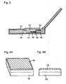
- Fig. 3 shows a notebook type computer 101 according to the third exemplary embodiment.
- the computer 101 includes a vacuum thermal insulator 105 separating between a heating component 103 on an internal main board 102 and a bottom of a device enclosure 104, another vacuum thermal insulator 109 separating between the heating component 103 and an expansion unit mounting case 108, and a heat sink 106.
- This computer suppresses temperature rise on a surface of the device, and prevents heat from being transferred to a user, since it can effectively block transfer of the heat to the bottom surface.
- the computer also suppresses temperature rise of the external expansion unit so as to avoid malfunction of the unit, because the computer effectively blocks transfer of the heat to the external expansion unit.
- Fig. 4A is a perspective view of an expansion unit mounting case according to the fourth exemplary embodiment
- Fig. 4B is a side view of the same case.
- the vacuum thermal insulator 109 is attached to the expansion unit mounting case 108.
- Fig. 5 is a sectional view of each of vacuum thermal insulators 105 and 109 according to the fifth exemplary embodiment.
- a bag 110 is filled with a core member consisting of inorganic powder 111.
- Fig. 6 is a partly sectioned schematic illustration of the vacuum thermal insulator 105 or 109 according to the sixth exemplary embodiment.
- a bag 110 is filled with a core member consisting of inorganic fiber 112.
- Fig. 7 is a sectional view of one of vacuum thermal insulators 105 and 109 according to the seventh exemplary embodiment.
- a bag 110 is filled with a core member consisting of inorganic powder 111 and inorganic fiber 112.
- Fig. 8 is a sectional view of one of vacuum thermal insulators 105 and 109 according to the eighth exemplary embodiment.
- a bag 110 is filled with a core member consisting of continuously foamed polyurethane 113.
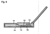
- Fig. 9 shows a notebook type computer 101 according to the ninth exemplary embodiment.
- the computer 101 includes a microporous body 114 consisting of dried gel for separating between a heating component 103 on an internal main board 102 and a device enclosure 104, and a heat sink 106.
- Each vacuum thermal insulator includes a core member and a bag which is filled with the core member and is sealed under a reduced pressure. Internal pressure of 100Torr or less is desirable, and 10Torr or less is more desirable. In addition, adsorbent may be used. In order to reduce a thickness of the notebook type computer, 5mm or less in thickness of the vacuum thermal insulator is desirable, and 2mm or less is even more desirable.
- the core member of the vacuum thermal insulator may employ a continuously foamed body made of polymeric material such as polystyrene and polyurethane, inorganic and organic powder, inorganic and organic fiber material, and the like. Inorganic powder, inorganic fiber, and mixture of them are especially preferable.
- the bag includes a surface protective layer, a gas barrier layer, and a heat welding layer, and each layer consists of a lamination of at least one type of film.
- the surface protective layer may employ an axially oriented product of polyethylene terephthalate film or polypropylene film and the like are.
- the gas barrier layer may employ a metallized film, an inorganic substance deposited film, a metal foil, and the like.
- a low density polyethylene film, a high density polyethylene film, a polypropylene film, a polyacrylonitrile film, a non-oriented polyethylene terephthalate film, and the like are used.
- pulverized inorganic materials such as agglomerate silica powder, pulverized powder of foamed pearlite, diatomaceous earth powder, calcium silicate powder, calcium carbonate powder, clay, talc, and the like can be used for the inorganic powder.
- Agglomerate silica powder having a secondary agglomerate diameter of 20 ⁇ m or less is especially desirable.
- Fiberized inorganic materials such as glass wool, ceramic fiber, rock wool, and the like can be used for the inorganic fiber. Their form such as unwoven fabric form, woven form, cottony form is not a matter of importance.
- organic binder may be used to aggregate the inorganic fiber.
- Microporous bodies exhibiting good heat insulating property including inorganic oxide aerogel such as silica aerogel, alumina aerogel, and so on, inorganic aerogel such as polyurethane aerogel, polyisocyanate aerogel, phenolic series aerogel, and the like are suitable for the microporous body of dried gel. Alternatively it can be a mixture of two or more kinds of aerogel. Further, any forms such as granular form and monolith form can be useful.
- the thermal insulator for blocking the heat transfer between the internal heating component and the device enclosure, and another thermal insulator for blocking the heat transfer between the heating component and the expansion unit mounting case can be used independently, or they may be used together.
- thermal insulators of the invention are not restricted to only those taught herein.
- Continuously foamed polyurethane was used for a core member of a vacuum thermal insulator.
- a bag consisting of a surface protective layer of polyethylene terephthalate film, a gas barrier layer of aluminum foil and a heat welding layer of non-oriented polypropylene was used.
- the bag was filled with the continuously foamed polyurethane, and it was sealed under a pressure of 0.1Torr, to prepare the vacuum thermal insulator.
- a thickness of the vacuum thermal insulator is 1.5mm.
- the vacuum thermal insulator was placed in the notebook type computer, as shown in Fig. 1 .
- a temperature measured on a bottom surface was 46°C, and an effectiveness of the insulation was verified since it was lower than a blank sample by 4°C.
- Agglomerate silica powder was used for a core member of a vacuum thermal insulator.
- the same bag as that described in the embodiment sample 1.1 was used.
- the bag was filled with the agglomerate silica powder, and it was sealed under a pressure of 0.1Torr, to prepare the vacuum thermal insulator.
- a thickness of the vacuum thermal insulator is 1.5mm.
- the vacuum thermal insulator was placed in the notebook type computer, as shown in Fig. 1 .
- a temperature measured on a bottom surface was 46°C, when measured, and an effectiveness of the insulation was verified since it was lower than a blank sample by 4°C.
- Inorganic fiber consisting of silica-alumina was used for a core member of vacuum thermal insulator.
- the same bag as that described in the embodiment sample 1.1 was used.
- the bag was filled with the inorganic fiber, and was sealed under a pressure of 0.1Torr, to prepare the vacuum thermal insulator.
- a thickness of the vacuum thermal insulator is 1.5mm.
- the vacuum thermal insulator was placed in the notebook type computer, as shown in Fig. 1 .
- a temperature measured on a bottom surface was lower than a blank sample by 5°C, and an effectiveness of the insulation was verified.
- the fibrous material raises no powdery dust, the insulator can be handled more easily than in the case of the embodiment sample 1.2.
- the insulator can be filled-in than that of the embodiment sample 1.1, since being flexible.
- a material used for a core member of a vacuum thermal insulator was prepared by preliminarily mixing agglomerate silica powder and inorganic fiber consisting of silica-alumina, and forming it in shape.
- the same bag as that described in the embodiment sample 1.1 was used.
- the bag was filled with the core member, and was sealed under a pressure of 0.1Torr, to prepare the vacuum thermal insulator.
- a thickness of the vacuum thermal insulator is 1.5mm.
- the vacuum thermal insulator was placed in the notebook type computer, as shown in Fig. 1 . A temperature measured on a bottom surface was lower than a blank sample by 5.5°C, and an effectiveness of the insulation was thus verified.
- a monolith body of silica aerogel in a thickness of 2mm was used for a microporous body of dried gel.
- This silica aerogel was placed in the notebook type computer, as shown in Fig. 6 .
- a temperature measured a bottom surface was lower than a blank sample by 4°C, and thus an effectiveness of the insulation was verified.
- the silica aerogel since providing the effectiveness of insulation without requiring vacuum-evacuation, put a less burden on manufacturing as compared to the vacuum thermal insulator.
- a temperature on a bottom surface of a notebook type computer not provided with a thermal insulator was 50°C.
- Polyurethane foam having 1.5mm thickness was used as a thermal insulator, and was placed in a notebook type computer in the same manner as the embodiment sample 1.5. Although a temperature on a bottom surface decreased by 1°C, the effectiveness of insulation was small.
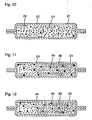
- Fig. 10 is a sectional view of vacuum thermal insulator 201 according to the tenth exemplary embodiment, in which encapsulating member 202 having a metallic foil layer and a thermoplastic polymer layer is filled with uniformly mixed fumed silica 203 and pulverized carbon material 204.
- the core member is filled and sealed in the encapsulating member under a reduced pressure.
- materials such materials as moisture adsorbent and gas absorbent may be used, including physical adsorbents such as synthetic zeolite, activated charcoal, active alumina, silica gel, dawsonite, hydrotalcite, and the like, as well as chemical absorbents such as oxides of alkali metal and alkaline earth metal, hydroxides, and the like.
- the core member may be put into the encapsulating member and sealed after being enclosed in an unwoven fabric. Or, the core member may be dried before being vacuum-sealed.
- Oxidized silicon compound having a variety of particulate diameters manufactured by dry processing such as silicic acid and the like made by the arc method, and silicic acid and the like made by pyrolysis may be used as the fumed silica.
- Mixture of fumed silica having a variety of particulate diameters can also be used.
- any products that are made irregularly during a period of change-over in mass production between A-product and B-product of respectively controlled particulate diameters may be used, even though particulate diameters of such products vary between those of A-product and B-product, since they are not controlled due to the change-over.
- the vacuum thermal insulators can be made at a lower cost. However, it is desirable to use those having an average primary particulate diameter of 50nm or less, if greater importance is attached to the thermal insulation property. Or, it is even more desirable to use those of 10nm or less if a better property is needed.
- carbon black any carbon materials such as carbon black, graphitized carbon powder, activated charcoal, acetylene black, and the like can be used as the pulverized carbon material, so long as they are pulverized.
- Carbon black is readily useful because it is widely available at reasonably low price.
- carbon black it is preferable to use those having a specific surface area of less than 100m 2 /g, in order to control time-dependent exhalation of gases and to maintain the excellent thermal insulation property for a long period of time. It is also preferable to use graphitized carbon powder for the same reasons.
- any material is usable if it is capable of sealing off the core member from the external air.
- Thin sheet metals such as stainless steel, aluminum, iron, and the like, or a laminated material of sheet metal and plastic film, and so on may be used.
- the laminated material may desirably be constructed with a surface protective layer, a gas barrier layer, and a heat welding layer.
- An axially oriented product of polyethylene terephthalate film or polypropylene film and the like are usable for the surface protective layer.
- a nylon film and the like upon being provided on an exterior surface, can increase flexibility, so as to improve a resistance to bending.
- a film of metallic foil such as aluminum and metallized film is usable for the gas barrier layer.
- the metallized film it is desirable to use the metallized film, however, in order to reduce a leakage of heat and to obtain good insulating effectiveness. It is preferable to use such materials as polyethylene terephthalate film, ethylene vinyl-alcohol copolymer film, polyethylene naphthalate film, and the like covered with vaporized metal deposit.
- a low-density polyethylene film, high-density polyethylene film, polypropylene film, polyacrylonitrile film, non-oriented polyethylene terephthalate film, and the like are usable.
- Fig. 11 is a sectional view of vacuum thermal insulator 201 according to the eleventh exemplary embodiment, in which encapsulating member 202 having a metallic foil layer and a thermoplastic polymer layer is filled with uniformly mixed fumed silica 205 of 50nm or less in average primary particulate diameter and pulverized carbon material 204.
- Fig. 12 is a sectional view of vacuum thermal insulator 201 according to the twelfth exemplary embodiment, in which encapsulating member 202 having a metallized film layer and a thermoplastic polymer layer is filled with uniformly mixed fumed silica 205 of 50nm or less in average primary particulate diameter and carbon black 206 having a specific surface area of less than 100m 2 /g.
- Fig. 13 is a sectional view of vacuum thermal insulator 201 according to the thirteenth exemplary embodiment, in which encapsulating member 202 having a metallized film layer and a thermoplastic polymer layer is filled with uniformly mixed fumed silica 205 of 50nm or less in average primary particulate diameter and graphitized carbon powder 207.
- Fig. 14 is a sectional view of vacuum thermal insulator 201 according to the fourteenth exemplary embodiment, in which encapsulating member 202 having a metallized film layer and a thermoplastic polymer layer is filled with uniformly mixed fumed silica 205 of 50nm or less in average primary particulate diameter and carbon black 206 having a specific surface area of less than 100 m 2 /g, which are prepackaged in unwoven fabric 208.
- Fig. 15 is a sectional view of notebook type computer 216 according to the fifteenth exemplary embodiment.
- vacuum thermal insulator 201 described in the fourteenth exemplary embodiment and heat sink 220, which shield between heating component 218 on main board 217 in the device and a bottom of device enclosure 219.
- the thermal insulator 201 contains fumed silica of excellent thermal insulation property as a base material, and pulverized carbon is uniformly distributed in the base material, thereby providing even better thermal insulation property than the insulator in which only the fumed silica is used as the core member.
- the encapsulating member since having a metallized film layer reduces leakage of heat, effectively blocks the heat transferred to the bottom surface.
- the pulverized carbon appropriate for the purpose obviates deterioration of the thermal insulation property over duration of time due to an increase in the internal pressure.
- the notebook type computer is described as an example, which represents a device that requires the insulation in an operating temperature ranging from the normal temperature to approx. 80°C, and therefore it is by no means restrictive.
- the present exemplary embodiment is also applicable to, for instance, a thermal insulation of a liquid crystal component from a heating component associated with a CPU in a vehicle navigation system equipped with a liquid crystal display panel.
- Fig. 16 shows mixing container 233 having stirring blades 232 used in the method of manufacturing a vacuum thermal insulator according to the sixteenth exemplary embodiment.
- the stirring blades provided for uniform distribution of powdery particles grind secondary and tertiary agglomerates of fumed silica contained in raw material. Since this makes the fumed silica suitable for being distributed uniformly in the pulverized carbon material, it can avoid deterioration of the thermal insulation property due to poor distribution developed partially.
- Fig. 17 shows mixing container 233 having stirring blades 232 used in the method of manufacturing a vacuum thermal insulator according to the seventeenth exemplary embodiment.
- the container 233 is so constructed that either the mixing container itself or rotor 234 in a bottom also rotates in addition to the rotation of the stirring blades 232.
- the powder is thus rotatory mixed. This reduces a time required for grinding secondary and tertiary agglomerates of the fumed silica contained in raw material, as compared to the mixing container used in the sixteenth exemplary embodiment, thereby performing more efficient process of uniform distribution.
- any mixing container is usable if having a stirring blade that is capable of grinding the secondary and tertiary agglomerates of the fumed silica contained in the raw material.
- a shape of the mixing container is not a matter of importance.
- Core member used here consists of 89wt% fumed silica of a variety of average primary particulate diameters, 10wt% carbon black having a specific surface area of 50m 2 /g as the pulverized carbon material, and 1% of other material, which are uniformly mixed in the mixing container equipped with stirring blades.
- the core member is packed into bags made of unwoven fabric of polyester. They are then packed in encapsulating members of laminate bag, each of which consists of a surface protective layer of polyethylene terephthalate film, a gas barrier layer of ethylene vinyl-alcohol copolymer film with metallized aluminum, and a heat welding layer of non-oriented polypropylene. And they are sealed under a pressure of 133Pa with a thermal welding machine, to obtain vacuum thermal insulators.
- Table 201 shows a resultant measurement of a coefficient of thermal conductivity for each of the vacuum thermal insulators.
- adding the carbon black into the fumed silica of a variety of average primary particulate diameters can improve the coefficient of thermal conductivity between 30% and 47%, as compared with the fumed silica containing no additives. Also, the improvements are more effective, since they reach 40% or greater especially when the average primary particulate diameter of the fumed silica is 50nm or smaller.
- Core member used here consists of 89wt% fumed silica having an average primary particulate diameter of 7nm, 10wt% carbon black having a variety of specific surface areas as the pulverized carbon material, and 1% of other material, which are uniformly mixed in a mixing container equipped with stirring blades.
- the core member is packed into bags made of unwoven fabric of polyester.
- encapsulating members of laminate bag each of which consists of a surface protective layer of polyethylene terephthalate film, a gas barrier layer of ethylene vinyl-alcohol copolymer film with metallized aluminum, and a heat welding layer of non-oriented polypropylene, and they are sealed under a pressure of 133Pa with a thermal welding machine, to obtain vacuum thermal insulators.
- Table 202 shows resultant measurement of a coefficient of thermal conductivity for each of the vacuum thermal insulators.
- adding the 10wt% carbon black of a variety of specific surface areas into the fumed silica can improve the coefficient of thermal conductivity between 43% and 51%, as compared with the fumed silica containing no additives.
- the coefficients of thermal conductivity become low after the elapse of ten days, when carbon black having a specific surface area of 100m 2 /g or larger is added. This is caused by an increase in the internal pressure due to gases exhaled by the carbon black.
- Core member used here consists of 59wt% fumed silica having an average primary particulate diameter of 7nm, 40wt% carbon black having a variety of specific surface areas as the pulverized carbon material, and 1% of other material, which are uniformly mixed in a mixing container equipped with stirring blades.
- the core member is packed into bags made of unwoven fabric of polyester. They are then packed in encapsulating members of laminate bag each of which consists of a surface protective layer of polyethylene terephthalate film, a gas barrier layer of ethylene vinyl-alcohol copolymer film with metallized aluminum, and a heat welding layer of non-oriented polypropylene. Then they are sealed under a pressure of 133Pa with a thermal welding machine, to obtain vacuum thermal insulators.
- Table 203 shows resultant measurement of a coefficient of thermal conductivity for each of the vacuum thermal insulators.
- adding the 40wt% carbon black of a variety of specific surface areas into the fumed silica can improve the coefficient of thermal conductivity between 37% and 43%, as compared with the fumed silica containing no additives.
- the coefficients of thermal conductivity become low after the elapse of ten days, when carbon black having a specific surface area of 100m 2 /g or larger is added. This is attributed to an increase in the internal pressure due to gases exhaled by the carbon black, since added amount of the carbon black is 40wt%, wherein the increase in pressure exerts influence on the coefficients of thermal conductivity more conspicuously than when 10wt% carbon black is added.
- Core member used here consists of 59wt% fumed silica having an average primary particulate diameter of 7nm, 40wt% graphitized carbon powder having two different specific surface areas, as the pulverized carbon material, and 1% of other material, which are uniformly mixed in a mixing container equipped with stirring blades.
- the core member is packed into bags made of unwoven fabric of polyester. They are then packed in encapsulating members of laminate bag, each of which consists of a surface protective layer of polyethylene terephthalate film, a gas barrier layer of ethylene vinyl-alcohol copolymer film with metallized aluminum, and a heat welding layer of non-oriented polypropylene. Then they are sealed under a pressure of 133Pa with a thermal welding machine, to obtain vacuum thermal insulators.
- Table 204 shows resultant measurement of a coefficient of thermal conductivity for each of the vacuum thermal insulators.
- adding the 40wt% graphitized carbon powder of two different specific surface areas into the fumed silica improves the coefficient of thermal conductivity between 39% and 41%, as compared with the fumed silica containing no additives.
- the graphitized carbon powder having a larger specific surface area gives greater effect to the improvement in coefficient of thermal conductivity.
- Core member used here consists of 89wt% fumed silica having an average primary particulate diameter of 7nm, 10wt% carbon black having a specific surface area of 50m 2 /g, as the pulverized carbon material, and 1% of other material, which are uniformly mixed in a mixing container equipped with stirring blades.
- the core member is packed into a bag made of unwoven fabric of polyester and then packed in an encapsulating member of laminate bag, which consists of a surface protective layer of polyethylene terephthalate film, a gas barrier layer of aluminum foil, and a heat welding layer of non-oriented polypropylene. Then the encapsulating member is sealed under a pressure of 133Pa with a thermal welding machine, to obtain a vacuum thermal insulator.
- a result of measurement with a heat flow meter of a practical coefficient of thermal conductivity of this vacuum thermal insulator, taking into account a leakage of heat, is 0.0033kcal/mh°C.
- Fumed silica and pulverized carbon material serving as core member, their mixing ratio and a method of mixing them in this embodiment are the same as that described in the embodiment sample 2.5.
- the core member is packed into a bag made of unwoven fabric of polyester. It is then packed in an encapsulating member of laminate bag, which consists of a surface protective layer of polyethylene terephthalate film, a gas barrier layer of ethylene vinyl-alcohol copolymer film with metallized aluminum, and a heat welding layer of non-oriented polypropylene. Then it is sealed under a pressure of 133Pa with a thermal welding machine, to obtain a vacuum thermal insulator.
- a result of measurement with a heat flow meter of a practical coefficient of thermal conductivity of this vacuum thermal insulator, taking into account a leakage of heat, is 0.0028kcal/mh°C, which shows an improvement in the coefficient of thermal conductivity over the embodiment sample 2.5 in which aluminum foil is specified for the gas barrier layer.
- the reason for this is that the leakage of heat is suppressed by the gas barrier layer of the encapsulating member, which is provided with the metallized aluminum on the ethylene vinyl-alcohol copolymer film.
- Core member used here consists of 89wt% fumed silica having an average primary particulate diameter of 7nm, 10wt% carbon black having a specific surface area of 50m 2 /g, as the pulverized carbon material, and 1% of other material, which are uniformly mixed in a mixing container equipped with stirring blades and a rotor rotated in a bottom portion of it.
- the core member is packed into a bag made of unwoven fabric of polyester. It is then packed in an encapsulating member of laminate bag, which consists of a surface protective layer of polyethylene terephthalate film, a gas barrier layer of ethylene vinyl-alcohol copolymer film with metallized aluminum, and a heat welding layer of non-oriented polypropylene. Then they are sealed under a pressure of 133Pa with a thermal welding machine, to obtain a vacuum thermal insulator.
- a result of measurement with a heat flow meter of a practical coefficient of thermal conductivity of this vacuum thermal insulator, taking into account a leakage of heat, is 0.0028kcal/mh°C, showing similar result to the embodiment sample 2.6.
- a mixture time can be shortened by 20% as compared with the embodiment sample 2.6, since the mixing container equipped with stirring blades mixes the core member by rotating together the rotor in the bottom portion.
- a vacuum thermal insulator containing fumed silica with average primary particulate diameter of 7nm, as described in the embodiment sample 2.1 is placed in a notebook type computer as shown in Fig. 15 .
- a temperature on a bottom surface of the computer is decreased by 5°C over the one not provided with the thermal insulator. Furthermore, in an accelerated test to evaluate deterioration of the thermal insulator, there is no verifiable deterioration in the thermal insulation property under the condition of a ten-year duration.
- Core member used for a vacuum thermal insulator here consists of 90wt% pearlite powder having an average particulate diameter of 8 ⁇ m, and 10wt% carbon black having a specific surface area of 50m 2 /g, as the pulverized carbon material, which are uniformly mixed in a mixing container equipped with stirring blades.
- the core member is packed into a bag made of unwoven fabric of polyester. It is then packed in an encapsulating member of laminate bag, which consists of a surface protective layer of polyethylene terephthalate film, a gas barrier layer of aluminum foil, and a heat welding layer of non-oriented polypropylene. Then they are sealed under a pressure of 133Pa with a thermal welding machine, to obtain the vacuum thermal insulator.
- a coefficient of thermal conductivity of this vacuum thermal insulator is 0.0052kcal/mh°C.
- a coefficient of thermal conductivity of another vacuum thermal insulator containing the pearlite powder only is 0.0065kcal/mh°C. Therefore, adding the 10wt% carbon black to the pearlite powder reduces only 20%, which is smaller in effect of improvement of the thermal insulation property as compared to those of the present exemplary embodiments.
- Core member used for a vacuum thermal insulator here consists of 90wt% pearlite powder having an average particulate diameter of 24 ⁇ m, and 10wt% carbon black having a specific surface area of 50m 2 /g, as the pulverized carbon material, which are uniformly mixed in a mixing container equipped with stirring blades.
- the core member is packed into a bag made of unwoven fabric of polyester. It is then packed in an encapsulating member of laminate bag, which consists of a surface protective layer of polyethylene terephthalate film, a gas barrier layer of aluminum foil, and a heat welding layer of non-oriented polypropylene. Then they are sealed under a pressure of 133Pa with a thermal welding machine, to obtain the vacuum thermal insulator.
- a coefficient of thermal conductivity of this vacuum thermal insulator is 0.0050kcal/mh°C.
- a coefficient of thermal conductivity of another vacuum thermal insulator containing the pearlite powder only is 0.0058kcal/mh°C.
- adding the 10wt% carbon black to the pearlite powder reduces the conductivity of only 15%, which is smaller in effect of improvement of the thermal insulation property than those of the present exemplary embodiments.
- Core member used for a vacuum thermal insulator here consists of 90wt% wet silica having an average primary particulate diameter of 20nm, and 10wt% carbon black having a specific surface area of 50m 2 /g, as the pulverized carbon material, which are uniformly mixed in a mixing container equipped with stirring blades.
- the core member is packed into a bag made of unwoven fabric of polyester. It is then packed in an encapsulating member of laminate bag, which consists of a surface protective layer of polyethylene terephthalate film, a gas barrier layer of aluminum foil, and a heat welding layer of non-oriented polypropylene. Then they are sealed under a pressure of 133Pa with a thermal welding machine, to obtain the vacuum thermal insulator.
- a coefficient of thermal conductivity of this vacuum thermal insulator is 0.0049kcal/mh°C.
- a coefficient of thermal conductivity of another vacuum thermal insulator containing the pearlite powder only is 0.0062kcal/mh°C.
- adding the 10wt% carbon black to the wet silica reduces the conductivity by only 20%, which is smaller in effect of improvement of the thermal insulation property as compared to those of the present exemplary embodiments.
- Core member used here consists of 90wt% fumed silica having an average primary particulate diameter of 7nm, 9wt% carbon black having a specific surface area of 50m 2 /g, as the pulverized carbon material, and 1% of other material, which are mixed and stirred in a mixing container not equipped with stirring blades but only a rotor in the bottom of it. Agglomerates of the fumed silica are produced in the core member because the material is not uniformly mixed.
- the core member is packed into a bag made of unwoven fabric of polyester.
- an encapsulating member of laminate bag which consists of a surface protective layer of polyethylene terephthalate film, a gas barrier layer of ethylene vinyl-alcohol copolymer film provided with metallized aluminum, and a heat welding layer of non-oriented polypropylene. Then they are sealed under a pressure of 133Pa with a thermal welding machine, to obtain the vacuum thermal insulator.
- a coefficient of thermal conductivity of this vacuum thermal insulator is 0.0048kcal/mh°C.
- a vacuum thermal insulator described in the comparative sample 2.3 is placed in a notebook type computer as shown in Fig. 15 .
- a temperature on a bottom surface of the computer is decreased only by 2°C over the one not provided with the thermal insulator, indicating a poorer effect of thermal insulation than that of the embodiment sample 2.8.
- Fig. 18 is a sectional view of a vacuum thermal insulator in the eighteenth exemplary embodiment.
- Vacuum thermal insulator 301 includes compact body 302 made from mixture of powder 303 and fibrous material 304, and enveloping member 305 for covering the compact body 302. They are sealed with the inside decompressed.
- the compact body 302 is formed in a manner that 90wt% dry silica having an average primary particulate diameter of 7nm and 10wt% glass wool with an average fiber diameter of 7 ⁇ m are uniformly mixed in a cutter mill, put in a molding die, and compressed with a pressure of 1.2N/mm 2 .
- the compact body 302 had a compact density of 190kg/m 3 under the atmospheric pressure, and has a coefficient of thermal conductivity of 0.026W/mK under the atmospheric pressure.
- a bending strength of the compact body 302 is 0.21N/mm 2 .
- the compact body 302 is dried for one hour at 110°C, inserted into the enveloping member 305, and an interior of the enveloping member 305 is decompressed to 20Pa and sealed.
- the enveloping member 305 is provided with a surface protective layer of polyethylene terephthalate (12 ⁇ m in thickness), a film layer of ethylene vinyl-alcohol copolymer composite (15 ⁇ m in thickness) with metallized aluminum deposited on an interior side, and a heat seal layer of high density polyethylene (50 ⁇ m in thickness).
- the enveloping member 305 is sealed at four sides, which leaves fin 306 around its periphery.
- a coefficient of thermal conductivity of the vacuum thermal insulator 301 is 0.0062W/mK at an average temperature of 24°C.
- the compact body has a thickness D301 before being inserted into the enveloping member, and has a thickness D302 after being included in the vacuum thermal insulator.
- Fig. 18 represents a sectional view of a vacuum thermal insulator in the nineteenth exemplary embodiment.
- Vacuum thermal insulator 301A includes compact body 302A.
- the compact body 302A is composed in a manner that powder 303A made of 85.5wt% dry silica having an average primary particulate diameter of 7nm mixed with 4.5wt% carbon black having an average particulate diameter of 42nm is further mixed with 10wt% glass wool of 7 ⁇ m in an average fiber diameter as fibrous material 304.
- the compact body 302A is so formed that after the powder 303A is mixed in a cutter mil, it is further mixed with the fibrous material 304 added to it, put in a molding die, and compressed with a pressure of 1.2N/mm 2 .
- the compact body 302A has a compact density of 190kg/m 3 under the atmospheric pressure, and has a coefficient of thermal conductivity is 0.022W/mK under the atmospheric pressure. This is a coefficient of thermal conductivity superior to the static electricity so that this compact body can provide for a good insulating efficiency even if being used under the normal atmosphere instead of making it into a vacuum thermal insulator.
- a bending strength of the compact body 302A is 0.21N/mm 2 .
- the compact body 302A is dried for one hour at 110°C, inserted into enveloping member 305, and an interior of it is decompressed to 20Pa and sealed.
- the enveloping member 305 is analogous to that of the eighteenth exemplary embodiment.
- a coefficient of thermal conductivity of the vacuum thermal insulator 301A is 0.005W/mK at an average temperature of 24°C.
- the compact body has a thickness D301 before being inserted into the enveloping member, and has a thickness D302 after being included in the vacuum thermal insulator.
- Table 301 shows results of the evaluation.
- the coefficient of thermal conductivity is substantially reduced by adding the carbon black, as compared with the vacuum thermal insulator 301 described in the eighteenth exemplary embodiment.
- Fig. 18 represents a sectional view of a vacuum thermal insulator in the twentieth exemplary embodiment.
- Vacuum thermal insulator 301B includes a compact body 302B.
- the compact body 302B is composed in a manner that powder 303B made of 85.5wt% dry silica having an average primary particulate diameter of 7nm mixed with 4.5 wt% titanium oxide having an average particulate diameter of 60nm is further mixed with 10wt% glass wool of 7 ⁇ m in an average fiber diameter as fibrous material 304.
- the compact body 302B is so formed that after the powder 303B is mixed in a cutter mil, it is further mixed with the fibrous material 304 added to it, put in a molding die, and compressed with a pressure of 1.2N/mm 2 .
- the compact body 302B has a compact density of 180kg/m 3 under the atmospheric pressure, and has a coefficient of thermal conductivity of 0.025W/mK under the atmospheric pressure.
- a bending strength of the compact body 302B is 0.2N/mm 2 .
- the compact body 302B is dried for one hour at 110°C, inserted into enveloping member 305, and an interior of it is decompressed to 20Pa and sealed.
- the enveloping member 305 is analogous to that of the eighteenth exemplary embodiment.
- a coefficient of thermal conductivity of the vacuum thermal insulator 301B is 0.0062W/mK at an average temperature of 24°C.
- the compact body has thickness D301 before being inserted into the enveloping member, and has has thickness D302 after being included in the vacuum thermal insulator.
- Table 301 shows results of the evaluation.
- Fig. 18 is a sectional view of a vacuum thermal insulator in the twenty-first exemplary embodiment.
- Vacuum thermal insulator 301C includes a compact body 302C.
- the compact body 302C is composed by mixing 90wt% dry silica having an average primary particulate diameter of 7nm, as powder 303, with 10wt% glass wool of 0.8 ⁇ m in an average fiber diameter, as fibrous material 304A.
- the compact body 302C is produced in the same manner as the eighteenth exemplary embodiment.
- the compact body 302C has a compact density of 180kg/m 3 under the atmospheric pressure, a coefficient of thermal conductivity of 0.025W/mK also under the atmospheric pressure, and a bending strength of 0.24N/mm 2 .
- the vacuum thermal insulator 301C is produced in the same method as the eighteenth exemplary embodiment.
- the enveloping member 305 is also analogous to that of the eighteenth exemplary embodiment.
- a coefficient of thermal conductivity of the vacuum thermal insulator 301C is 0.0057W/mK at an average temperature of 24°C. It has 1% in ratio of change in the thickness.
- Table 301 shows results of the evaluation.
- Fig. 18 represents a sectional view of a vacuum thermal insulator in the twenty-second exemplary embodiment.
- Vacuum thermal insulator 301D includes a compact body 302D.
- the compact body 302D is composed in a manner that powder 303A made of 85.5wt% dry silica having an average primary particulate diameter of 7nm mixed with 4.5wt% carbon black having an average particulate diameter of 42nm is further mixed with 10wt% glass wool 304A of 0.8 ⁇ m in an average fiber diameter.
- the compact body 302D is produced in the same manner as the nineteenth exemplary embodiment.
- the compact body 302D has a compact density of 180kg/m 3 under the atmospheric pressure, a coefficient of thermal conductivity of 0.02W/mK also under the atmospheric pressure, and a bending strength of 0.25N/mm 2 .
- the vacuum thermal insulator 301D is produced in the same method as the nineteenth exemplary embodiment.
- the enveloping member 305 is also analogous to that of the nineteenth exemplary embodiment.
- a coefficient of thermal conductivity of the vacuum thermal insulator 301D is 0.0044W/mK at an average temperature of 24°C, and it has 1% in ratio of change in the thickness.
- Table 301 shows results of the evaluation.
- Fig. 18 represents a sectional view of a vacuum thermal insulator in the twenty-third exemplary embodiment.
- Vacuum thermal insulator 301E includes a compact body 302E.
- the compact body 302E is composed in a manner that powder 303A made of 85.5wt% dry silica having an average primary particulate diameter of 7nm mixed with 4.5wt% carbon black having an average particulate diameter of 42nm is further mixed with 10wt% glass wool, as fibrous material 304A of 0.8 ⁇ m in an average fiber diameter.
- the compact body 302E is produced in the same manner as the nineteenth exemplary embodiment, except that the compressing pressure is set to 0.4N/mm 2 .
- the compact body 302E has a compact density of 140kg/m 3 under the atmospheric pressure, a coefficient of thermal conductivity of 0.02W/mK also under the atmospheric pressure, and a bending strength of 0.14N/mm 2 .
- the vacuum thermal insulator 301E is produced in the same method as the nineteenth exemplary embodiment.
- Enveloping member 305 of the same specification as that of the nineteenth exemplary embodiment is also used.
- a coefficient of thermal conductivity of the vacuum thermal insulator 301E is 0.0042W/mK at an average temperature of 24°C, and it has 3% in ratio of change in the thickness.
- Table 301 shows results of the evaluation.
- Fig. 19 is a sectional view of a vacuum thermal insulator in the twenty-fourth exemplary embodiment.
- Vacuum thermal insulator 301F includes a compact body 302F.
- the compact body 302F is composed in a manner that powder 303C made of 85.5wt% dry silica having an average primary particulate diameter of 56nm mixed with 9.5wt% carbon black having an average particulate diameter of 42nm is further mixed with 5wt% fibrous material 304 consisting of glass wool having 7 ⁇ m in an average fiber diameter.
- the compact body 302F is formed in a manner that the dry silica, the carbon black and the glass wool are mixed simultaneously in a cutter mill, put in a molding die, and compressed with a pressure of 1.2N/mm 2 .
- the compact body 302F has a compact density of 180kg/m 3 under the atmospheric pressure, and has a coefficient of thermal conductivity of 0.021W/mK also under the atmospheric pressure, and a bending strength of 0.21N/mm 2 .
- the compact body 302F is dried for one hour at 110°C, inserted into enveloping member 305A together with adsorbent 307, and an interior of the enveloping member 305A is decompressed to 20Pa and sealed.
- One side of the enveloping member 305A is formed with a lamination film including an outermost layer of a nylon film (15 ⁇ m in thickness), a surface protective layer of polyethylene terephthalate (12 ⁇ m in thickness), an intermediate part of aluminum foil (6 ⁇ m in thickness), and a heat seal layer of high density polyethylene (50 ⁇ m in thickness).
- the other side is formed also with a lamination film comprising an outermost layer of a nylon film (15 ⁇ m in thickness), a surface protective layer of polyethylene terephthalate (12 ⁇ m in thickness), an intermediate part of film layer comprised of ethylene vinyl-alcohol copolymer composite (15 ⁇ m in thickness) with metallized aluminum deposited on an interior side, and a heat seal layer of high density polyethylene (50 ⁇ m in thickness).
- the adsorbent 307 is moisture adsorbent composed of granulated calcium oxide placed in a bag having moisture permeability.
- the vacuum thermal insulator 301F constructed as above has a coefficient of thermal conductivity of 0.0049W/mK at an average temperature of 24°C, and a ratio of 1% in change of the thickness.
- Table 301 shows results of the evaluation.
- the insulator has an equivalent coefficient of thermal conductivity to that of the vacuum thermal insulator 301A because an added amount of the fibrous material is reduced.
- Adding the adsorbent 307 improves reliability over the elapse of time.
- Fig. 18 represents a sectional view of a vacuum thermal insulator in the twenty-fifth exemplary embodiment.
- Vacuum thermal insulator 301G includes a compact body 302G.
- the compact body 302G is composed in a manner that powder 303D made of 64wt% dry silica having an average primary particulate diameter of 7nm mixed with 16wt% carbon black having an average particulate diameter of 30nm is further mixed with fibrous material 304B made of 10wt% silica-alumina fiber having an average fiber diameter of 1.1 ⁇ m mixed with 10wt% glass wool having an average fiber diameter of 8 ⁇ m.
- the compact body 302G is produced in the same manner as the nineteenth exemplary embodiment, except that the compressing pressure is set to 1.5N/mm 2 .
- the compact body 302G has a compact density of 200kg/m 3 under the atmospheric pressure, a coefficient of thermal conductivity of 0.022W/mK also under the atmospheric pressure, and a bending strength of 0.23N/mm 2 .
- the compact body 302G is dried for one hour at 110°C, inserted into enveloping member 305B, and an interior of the enveloping member 305B is decompressed to 20Pa and sealed.
- One side of the enveloping member 305B includes an outermost layer of nylon (12 ⁇ m in thickness), an intermediate part of film layer made of polyethylene terephthalate (12 ⁇ m in thickness) deposited on an inner side with metallized aluminum, another film layer inside of it made of ethylene vinyl-alcohol copolymer film (12 ⁇ m in thickness) deposited on an outer surface with metallized aluminum, and a heat seal layer of polypropylene (50 ⁇ m in thickness).
- the other side includes an outermost layer of nylon (12 ⁇ m in thickness), a surface protective layer of polyethylene terephthalate (12 ⁇ m in thickness), an intermediate part of aluminum foil (6 ⁇ m in thickness), and a heat seal layer of polypropylene (50 ⁇ m in thickness).
- the vacuum thermal insulator 301G has a coefficient of thermal conductivity of 0.0050W/mK at an average temperature of 24°C, and a ratio of 1% in change of the thickness.
- Table 301 shows results of the evaluation.
- the fiber is blended in consideration of a balance between a reduction in the coefficient of thermal conductivity due to fining of the fiber diameter and a reduction in cost due to increase of the fiber diameter, upon comparison with the vacuum thermal insulator 301A in the nineteenth exemplary embodiment.
- An increase of the compression pressure provides the vacuum thermal insulator with outstanding improvement to the bending strength and the ratio of change in thickness, while maintaining the coefficient of thermal conductivity generally unchanged.
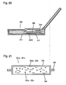
- Fig. 20 is a sectional view of a notebook type computer according to the twenty-sixth exemplary embodiment.
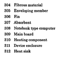
- the notebook type computer 308 is provided with vacuum thermal insulator 301D and heat sink 312, which shield between heating component 310 on main board 309 in the device and a bottom of device enclosure 311.
- a temperature on the bottom surface of the notebook type computer 308 is lower by 5°C than that of the notebook type computer not provided with a vacuum thermal insulator.
- Fig. 21 is a sectional view of a vacuum thermal insulator of the comparative sample 3.1.
- Vacuum thermal insulator 301a has compact body 302a containing mixture of powder 303a and fibrous material 304.
- the compact body 302a is inserted in the enveloping member 305, and an interior of the enveloping member 305 is decompressed and sealed.
- the compact body 302a is formed in a manner that 90wt% dry silica having an average secondary particulate diameter of 150nm as powder 303a and 10wt% glass wool having an average fiber diameter of 7 ⁇ m as fibrous material 304 are uniformly mixed in a cutter mill, are put into a molding die, and are compressed with a pressure of 1.2N/mm 2 .
- the compact body 302a is very brittle that it crumbles partially when picked up with a hand, and it also raises heavy powdery dust.
- the compact body 302a has a compact density of 250kg/m 3 under the atmospheric pressure, a coefficient of thermal conductivity of 0.032W/mK under the atmospheric pressure, and a bending strength of 6.03N/mm 2 .
- the compact body 302a is dried for one hour at 110°C, and inserted carefully into the enveloping member 305 while being carried on a plastic board. After the plastic board is removed, inside of the enveloping member 305 is decompressed to 20Pa, and sealed.
- the enveloping member 305 is analogous to that of the eighteenth exemplary embodiment.
- the vacuum thermal insulator 301a has a coefficient of thermal conductivity of 0.0068W/mK at an average temperature of 24°C and a ratio of 7% in change of the thickness, and the insulator has a rough surface.
- Table 302 shows results of the evaluation of the vacuum thermal insulator 301a.
- the insulator includes the powder of large particulate diameter as compared to the vacuum thermal insulator described in the eighteenth exemplary embodiment, the compact body is not obtained easily, and has a small bending strength.
- Fig. 21 represents a sectional view of a vacuum thermal insulator of the comparative sample 3.2.
- Vacuum thermal insulator 301b is provided with compact body 302b.
- the compact body 302b is composed through that powder 303b made of 85.5wt% wet silica having an average primary particulate diameter of 120nm mixed with 4.5wt% carbon black having an average particulate diameter of 42nm is further mixed with 10wt% glass wool of 7 ⁇ m in an average fiber diameter as fibrous material 304.
- the compact body 302b is formed in a manner that after the powder 303b is mixed in a cutter mil, it is further mixed with the fibrous material 304 added to it, is put in a molding die, and is compressed with a pressure of 1.2N/mm 2 .
- the compact body 302b is very brittle that it crumbles partially when picked up with a hand and it also raises heavy powdery dust.
- the compact body 302b has a compact density of 250kg/m 3 under the atmospheric pressure, a coefficient of thermal conductivity of 0.028W/mK under the atmospheric pressure, and a bending strength of 0.03 N/mm 2 .
- the compact body 302b is dried for one hour at 110°C, and inserted carefully into the enveloping member 305 while being carried on a plastic board. After the plastic board is removed, inside of the enveloping member 305 is decompressed to 20Pa, and sealed.
- the enveloping member 305 is analogous to that of the eighteenth exemplary embodiment.
- the vacuum thermal insulator 301b has a coefficient of thermal conductivity of 0.0053W/mK at an average temperature of 24°C, a ratio of 7% in change of the thickness, and it has a rough surface.
- Table 302 shows results of the evaluation.
- the insulator uses the powder of large particulate diameter as compared to the vacuum thermal insulator 301A of the nineteenth exemplary embodiment, the compact body is not obtained easily, and it has a small bending strength.
- Fig. 21 represents a sectional view of a vacuum thermal insulator of the comparative sample 3.3.
- Vacuum thermal insulator 301c is provided with compact body 302c.
- the compact body 302c is composed through that powder 303c made of 45wt% dry silica having an average primary particulate diameter of 7nm mixed with 45wt% wet silica having an average primary particulate diameter of 130nm is further mixed with 10wt% glass wool as fibrous material 304 of 7 ⁇ m in an average fiber diameter.
- the compact body 302c is formed in a manner that after the powder 303c is mixed in a cutter mil, it is further mixed with the fibrous material 304 added to it, is put in a molding die, and is compressed with a pressure of 1N/mm 2
- the compact body 302c is very brittle that it crumbles partially when picked up with a hand, and it also raises heavy powdery dust.
- the compact body 302c has a compact density of 230kg/m 3 under the atmospheric pressure, a coefficient of thermal conductivity of 0.028W/mK under the atmospheric pressure, and a bending strength of 0.05N/mm 2 .
- the compact body 302c is dried for one hour at 110°C, and inserted carefully into the enveloping member 305 while being carried on a plastic board. After the plastic board is removed, inside of the enveloping member 305 is decompressed to 20Pa, and sealed.
- the enveloping member 305 is analogous to that of the eighteenth exemplary embodiment.
- the vacuum thermal insulator 301c has a coefficient of thermal conductivity of 0.0064W/mK at an average temperature of 24°C, a ratio of 6% in change of the thickness, and it has a rough surface.
- Table 302 shows results of the evaluation.
- the compact body Since it is blended with the wet silica of large particulate diameter as compared to the vacuum thermal insulator 301 described in the eighteenth exemplary embodiment, the compact body is not obtained easily, and it has a small bending strength.
- a portable information device such as a low-profile notebook type computer which has a highly efficient thermal insulator capable of blocking a transfer of heat between an internal heating component and a device enclosure so as to reduce temperature rise on a surface of the device.
- a portable information device is further provided which has an efficient thermal insulator for blocking a transfer of heat between the heating component and an expansion unit mounting case, thereby alleviating malfunction and temperature rise of the external expansion unit.
Landscapes
- Life Sciences & Earth Sciences (AREA)
- Engineering & Computer Science (AREA)
- Health & Medical Sciences (AREA)
- General Health & Medical Sciences (AREA)
- Dentistry (AREA)
- Environmental Sciences (AREA)
- Plant Pathology (AREA)
- Pest Control & Pesticides (AREA)
- Agronomy & Crop Science (AREA)
- Wood Science & Technology (AREA)
- Zoology (AREA)
- Theoretical Computer Science (AREA)
- Toxicology (AREA)
- Computer Hardware Design (AREA)
- Human Computer Interaction (AREA)
- Physics & Mathematics (AREA)
- General Engineering & Computer Science (AREA)
- General Physics & Mathematics (AREA)
- Thermal Insulation (AREA)
Abstract
Description
- The present invention relates to a portable information device such as a notebook type computer, and more particularly to a portable information device that avoids heat generated in it from being transferred to a user, and prevents malfunction.
- When heat generated within a portable information device such as a notebook type computer of recent years is transferred to a surface of a device enclosure, and raises temperature of the surface of the device enclosure, the heat on a portion of the enclosure surface that stays in contact for a long time with a body of a user of the device gives an uncomfortable feeling to the user. Sources of the heat within the computer are mainly a CPU and power supply, and a surface temperature of the CPU, in particular, reaches such a temperature that exceeds approx. 100°C.
- As the latest techniques under these circumstances, there have been proposed some techniques in that thermal insulators are used to block heat between a heating component in the device and the device enclosure.
- There has been proposed, for instance, a notebook type computer of a structure including a thermal insulator for isolating between a heating component in the device and a device enclosure, a heat sink disposed to a back surface of a display unit, a heat pipe for conducting heat generated in the device to the heat sink, and an air vent, as disclosed in Japanese Patent Laid-open Publication, No.
11-202978 11-202978 - However, it is necessary to increase a thickness of the thermal insulator in order to attain an effect of reducing an amount of heat transferred to the surface of the device enclosure, because the effect is small if thermal insulation property of the thermal insulator is low. On the other hand, since low-profiling and weight-reduction are desired in these days for notebook type computers, it is also necessary for the thermal insulators to be small and light weight.
- Besides, the heat generated within a device may cause an adverse effect to external expansion terminals such as a random-access memory (RAM) card and a local area network (LAN) card, and leads them into malfunction.
- As ordinary thermal insulators, fibrous body such as glass wool, and foam body such as polyurethane foam and the like are used. In order to improve insulating properties of these thermal insulators, however, it is necessary to increase their thicknesses. The thicknesses are therefore not suitable to a need to save or use spaces efficiently due to limitation in the spaces available for installation of the thermal insulators.
- As one of the ways to solve the problem, a vacuum thermal insulator including a core member, which maintains a space, and an enveloping member, which shields the space from the open air is available. Pulverulent material, fibrous material, continuously-formed foam body, and the like are used generally as the core member. However, even more efficient vacuum thermal insulators are now in demand.
- Thus, Japanese Patent Laid-open Publication, No.
60-33479 - Furthermore, Japanese Patent Laid-open Publication, No.
61-36595 - Moreover, Japanese Patent Examined Publication, No.
08-20032 - With regard to the pearlite in Patent Publication
60-33479 61-36595 8-20032 - In the specification that uses carbon black as the pulverized carbon, the carbon black exhales gas over time, since it generally is a sooty product obtained through imperfect combustion of oil content and it contains organic gas as impurity. Thus, it has had a problem that an increase in an internal pressure of the vacuum thermal insulator causes degradation of the thermal insulation property. In addition, reaction-active radicals such as carbonyl group present in the carbon black at ends of their molecular structures react with moisture in air so as to also produce gas over time, thereby increasing the internal pressure of the vacuum thermal insulator and degrading the thermal insulation property in the similar manner.
- Porous bodies are generally used as the core member, which can be classified broadly into one of continuous foam, fibrous group, and pulverulent group.
- Among them, silica powder is often used as one of the pulverulent group vacuum insulator materials. Vacuum thermal insulator that uses silica powder is superior in the thermal insulation property over a long duration of time, although it falls behind the fibrous group material in the initial thermal insulation property.
- However, because being powdery, this material has poor workability, and is hardly formed in an irregular shape since the powder is to be enveloped in an inner bag when being used. Moreover, it also impairs work environment as the powder disperses when being disposed. There have been some attempts for improvement by making silica powder into compact form. However, various kinds of binder need to be used because of difficulties in molding the silica powder itself into porous bodies.
- For instance, Japanese Patent Examined Publication, No.
04-46348 - This includes a form having radiation inhibitor compressed, if there are large gradients in temperature between the wet silica and the fiber reinforcement and between walls in which the vacuum thermal insulator is used.
- Moreover, Japanese Patent Examined Publication, No.
05-66341 - A compact body is formed in which the dry silica and the wet silica supplement each other by their respective features of low coefficient of thermal conductivity and easiness of press-working, with addition of mixing fiber reinforcement into it.
- However, it is not feasible to form the body only with the silica powder.
- Even if the wet silica is mixed, stirred, and compression-formed with fibrous material, as taught in Patent Publication, No.
04-46348 - Furthermore, even if being formed by mixing and stirring the wet silica, dry silica and the fiber reinforcement, and compression forming them, as taught by Patent Publication, No.
05-66341 - Document
JP 11 202978 - It is an object of the present invention to provide for a portable information device, such as a low-profile notebook type computer, which has a highly efficient thermal insulator capable of blocking a transfer of heat between an internal heating component and a device enclosure, so as to reduce temperature rise on a surface of the device.
- This is achieved by the features as set forth in
claim 1. Further advantageous embodiments of the present invention are set forth in the dependent claims. - A portable information device such as a notebook type computer having a highly efficient thermal insulator blocks a transfer of heat between an internal heating component and a device enclosure without causing impediment to a low-profile design. This information device suppresses temperature rise on a surface of the device, so as not to give uncomfortable feeling to a user. The information device is also provided with an efficient thermal insulator for blocking a transfer of heat between the internal heating component and a built-in mounting case of an external expansion unit, thereby suppressing temperature rise of the external expansion unit and preventing malfunction of the unit.
-
-
Fig. 1 is a schematic view of a notebook type computer according to a first exemplary embodiment of the present invention; -
Fig. 2 is a schematic view of a notebook type computer according to a second exemplary embodiment of the invention; -
Fig. 3 is a schematic view of a notebook type computer according to a third exemplary embodiment of the invention; -
Fig. 4A and Fig. 4B are schematic illustrations of an expansion unit mounting case according to a fourth exemplary embodiment of the invention; -
Fig. 5 is a sectional view of a vacuum thermal insulator according to a fifth exemplary embodiment of the invention; -
Fig. 6 is a sectional view of a vacuum thermal insulator according to a sixth exemplary embodiment of the invention; -
Fig. 7 is a sectional view of a vacuum thermal insulator according to a seventh exemplary embodiment of the invention; -
Fig. 8 is a sectional view of a vacuum thermal insulator according to an eighth exemplary embodiment of the invention; -
Fig. 9 is a schematic view of a notebook type computer according to a ninth exemplary embodiment of the invention; -
Fig. 10 is a sectional view of a vacuum thermal insulator according to a tenth exemplary embodiment of the invention; -
Fig. 11 is a sectional view of a vacuum thermal insulator according to an eleventh exemplary embodiment of the invention; -
Fig. 12 is a sectional view of a vacuum thermal insulator according to a twelfth exemplary embodiment of the invention; -
Fig. 13 is a sectional view of a vacuum thermal insulator according to a thirteenth exemplary embodiment of the invention; -
Fig. 14 is a sectional view of a vacuum thermal insulator according to a fourteenth exemplary embodiment of the invention; -
Fig. 15 is a sectional view of a notebook type computer according to a fifteenth exemplary embodiment of the invention; -
Fig. 16 illustrates a mixing container according to a sixteenth exemplary embodiment of the invention; -
Fig. 17 illustrates another mixing container according to a seventeenth exemplary embodiment of the invention; -
Fig. 18 is a sectional view of a vacuum thermal insulator representing all of eighteenth through twenty-third and twenty-fifth exemplary embodiments of the invention; -
Fig. 19 is a sectional view of a vacuum thermal insulator according to a twenty-fourth exemplary embodiment of the invention; -
Fig. 20 is a sectional view of a notebook type computer according to a twenty-sixth exemplary embodiment of the invention; and -
Fig. 21 is a sectional view of a vacuum thermal insulator of comparative samples 3.1 to 3.3. -
Fig. 1 shows anotebook type computer 101 according to the first exemplary embodiment. Thecomputer 101 includes a vacuumthermal insulator 105 separating betweenheating component 103 on an internalmain board 102 and a bottom of adevice enclosure 104, and aheat sink 106. This computer alleviates temperature rise on a surface of the device, and prevents heat from being transferred to a user, since it can effectively block transfer of the heat to the bottom surface. -
Fig. 2 shows anotebook type computer 101 according to the second exemplary embodiment. Thecomputer 101 includes a vacuumthermal insulator 105 separating between aheating component 103 on an internalmain board 102 and adevice enclosure 104 at its bottom side, and aheat sink 106. In this embodiment, the vacuum thermal insulator is formed into a shape of letter "L", to isolate a hard disk drive (HDD) from the heating component. This computer suppresses temperature rise on a surface of the device, and prevents heat from being transferred to a user, since it can effectively block transfer of the heat to the bottom surface. It also protects components that are sensitive to heat such as theHDD 107 within the device. -
Fig. 3 shows anotebook type computer 101 according to the third exemplary embodiment. Thecomputer 101 includes a vacuumthermal insulator 105 separating between aheating component 103 on an internalmain board 102 and a bottom of adevice enclosure 104, another vacuumthermal insulator 109 separating between theheating component 103 and an expansionunit mounting case 108, and aheat sink 106. This computer suppresses temperature rise on a surface of the device, and prevents heat from being transferred to a user, since it can effectively block transfer of the heat to the bottom surface. The computer also suppresses temperature rise of the external expansion unit so as to avoid malfunction of the unit, because the computer effectively blocks transfer of the heat to the external expansion unit. -
Fig. 4A is a perspective view of an expansion unit mounting case according to the fourth exemplary embodiment, andFig. 4B is a side view of the same case. The vacuumthermal insulator 109 is attached to the expansionunit mounting case 108. -
Fig. 5 is a sectional view of each of vacuumthermal insulators bag 110 is filled with a core member consisting ofinorganic powder 111. -
Fig. 6 is a partly sectioned schematic illustration of the vacuumthermal insulator bag 110 is filled with a core member consisting ofinorganic fiber 112. -
Fig. 7 is a sectional view of one of vacuumthermal insulators bag 110 is filled with a core member consisting ofinorganic powder 111 andinorganic fiber 112. -
Fig. 8 is a sectional view of one of vacuumthermal insulators bag 110 is filled with a core member consisting of continuously foamedpolyurethane 113. -
Fig. 9 shows anotebook type computer 101 according to the ninth exemplary embodiment. Thecomputer 101 includes amicroporous body 114 consisting of dried gel for separating between aheating component 103 on an internalmain board 102 and adevice enclosure 104, and aheat sink 106. - Each vacuum thermal insulator according to the above-described exemplary embodiments of this invention includes a core member and a bag which is filled with the core member and is sealed under a reduced pressure. Internal pressure of 100Torr or less is desirable, and 10Torr or less is more desirable. In addition, adsorbent may be used. In order to reduce a thickness of the notebook type computer, 5mm or less in thickness of the vacuum thermal insulator is desirable, and 2mm or less is even more desirable.
- The core member of the vacuum thermal insulator may employ a continuously foamed body made of polymeric material such as polystyrene and polyurethane, inorganic and organic powder, inorganic and organic fiber material, and the like. Inorganic powder, inorganic fiber, and mixture of them are especially preferable.
- The bag includes a surface protective layer, a gas barrier layer, and a heat welding layer, and each layer consists of a lamination of at least one type of film. The surface protective layer may employ an axially oriented product of polyethylene terephthalate film or polypropylene film and the like are. The gas barrier layer may employ a metallized film, an inorganic substance deposited film, a metal foil, and the like. For the heat welding layer, a low density polyethylene film, a high density polyethylene film, a polypropylene film, a polyacrylonitrile film, a non-oriented polyethylene terephthalate film, and the like are used.
- Any of pulverized inorganic materials such as agglomerate silica powder, pulverized powder of foamed pearlite, diatomaceous earth powder, calcium silicate powder, calcium carbonate powder, clay, talc, and the like can be used for the inorganic powder. Agglomerate silica powder having a secondary agglomerate diameter of 20µm or less is especially desirable.
- Fiberized inorganic materials such as glass wool, ceramic fiber, rock wool, and the like can be used for the inorganic fiber. Their form such as unwoven fabric form, woven form, cottony form is not a matter of importance. In addition, organic binder may be used to aggregate the inorganic fiber.
- Microporous bodies exhibiting good heat insulating property, including inorganic oxide aerogel such as silica aerogel, alumina aerogel, and so on, inorganic aerogel such as polyurethane aerogel, polyisocyanate aerogel, phenolic series aerogel, and the like are suitable for the microporous body of dried gel. Alternatively it can be a mixture of two or more kinds of aerogel. Further, any forms such as granular form and monolith form can be useful.
- In any of the above-described exemplary embodiments, the thermal insulator for blocking the heat transfer between the internal heating component and the device enclosure, and another thermal insulator for blocking the heat transfer between the heating component and the expansion unit mounting case can be used independently, or they may be used together.
- Described hereinafter are actual embodiment samples of the thermal insulators. However, the thermal insulators of the invention are not restricted to only those taught herein.
- Continuously foamed polyurethane was used for a core member of a vacuum thermal insulator. A bag consisting of a surface protective layer of polyethylene terephthalate film, a gas barrier layer of aluminum foil and a heat welding layer of non-oriented polypropylene was used. The bag was filled with the continuously foamed polyurethane, and it was sealed under a pressure of 0.1Torr, to prepare the vacuum thermal insulator. A thickness of the vacuum thermal insulator is 1.5mm. The vacuum thermal insulator was placed in the notebook type computer, as shown in
Fig. 1 . A temperature measured on a bottom surface was 46°C, and an effectiveness of the insulation was verified since it was lower than a blank sample by 4°C. - Agglomerate silica powder was used for a core member of a vacuum thermal insulator. The same bag as that described in the embodiment sample 1.1 was used. The bag was filled with the agglomerate silica powder, and it was sealed under a pressure of 0.1Torr, to prepare the vacuum thermal insulator. A thickness of the vacuum thermal insulator is 1.5mm. The vacuum thermal insulator was placed in the notebook type computer, as shown in
Fig. 1 . A temperature measured on a bottom surface was 46°C, when measured, and an effectiveness of the insulation was verified since it was lower than a blank sample by 4°C. In addition, it was easier to place the thermal insulator than in the case of the embodiment sample 1.1, because the insulator has flexibility. - Inorganic fiber consisting of silica-alumina was used for a core member of vacuum thermal insulator. The same bag as that described in the embodiment sample 1.1 was used. The bag was filled with the inorganic fiber, and was sealed under a pressure of 0.1Torr, to prepare the vacuum thermal insulator. A thickness of the vacuum thermal insulator is 1.5mm. The vacuum thermal insulator was placed in the notebook type computer, as shown in
Fig. 1 . A temperature measured on a bottom surface was lower than a blank sample by 5°C, and an effectiveness of the insulation was verified. In addition, since the fibrous material raises no powdery dust, the insulator can be handled more easily than in the case of the embodiment sample 1.2. The insulator can be filled-in than that of the embodiment sample 1.1, since being flexible. - A material used for a core member of a vacuum thermal insulator was prepared by preliminarily mixing agglomerate silica powder and inorganic fiber consisting of silica-alumina, and forming it in shape. The same bag as that described in the embodiment sample 1.1 was used. The bag was filled with the core member, and was sealed under a pressure of 0.1Torr, to prepare the vacuum thermal insulator. A thickness of the vacuum thermal insulator is 1.5mm. The vacuum thermal insulator was placed in the notebook type computer, as shown in
Fig. 1 . A temperature measured on a bottom surface was lower than a blank sample by 5.5°C, and an effectiveness of the insulation was thus verified. In addition, since powder and fiber are mixed, their void dimensions became smaller than those of the embodiment samples 1.2 and 1.3, and thus the insulating property was improved. Also, the insulator is handled more easily than in the case of the embodiment sample 1.2, since it did not raise powdery dust. Furthermore, the insulator is filled-in more easily than that of the embodiment sample 1.1, since being flexible. - A monolith body of silica aerogel in a thickness of 2mm was used for a microporous body of dried gel. This silica aerogel was placed in the notebook type computer, as shown in
Fig. 6 . A temperature measured a bottom surface was lower than a blank sample by 4°C, and thus an effectiveness of the insulation was verified. The silica aerogel, since providing the effectiveness of insulation without requiring vacuum-evacuation, put a less burden on manufacturing as compared to the vacuum thermal insulator. - A temperature on a bottom surface of a notebook type computer not provided with a thermal insulator was 50°C.
- Polyurethane foam having 1.5mm thickness was used as a thermal insulator, and was placed in a notebook type computer in the same manner as the embodiment sample 1.5. Although a temperature on a bottom surface decreased by 1°C, the effectiveness of insulation was small.
-
Fig. 10 is a sectional view of vacuumthermal insulator 201 according to the tenth exemplary embodiment, in which encapsulatingmember 202 having a metallic foil layer and a thermoplastic polymer layer is filled with uniformly mixed fumedsilica 203 and pulverizedcarbon material 204. - In a vacuum thermal insulator, the core member is filled and sealed in the encapsulating member under a reduced pressure. In addition, such materials as moisture adsorbent and gas absorbent may be used, including physical adsorbents such as synthetic zeolite, activated charcoal, active alumina, silica gel, dawsonite, hydrotalcite, and the like, as well as chemical absorbents such as oxides of alkali metal and alkaline earth metal, hydroxides, and the like. Alternatively, the core member may be put into the encapsulating member and sealed after being enclosed in an unwoven fabric. Or, the core member may be dried before being vacuum-sealed.
- Oxidized silicon compound having a variety of particulate diameters manufactured by dry processing, such as silicic acid and the like made by the arc method, and silicic acid and the like made by pyrolysis may be used as the fumed silica. Mixture of fumed silica having a variety of particulate diameters can also be used. For instance, any products that are made irregularly during a period of change-over in mass production between A-product and B-product of respectively controlled particulate diameters may be used, even though particulate diameters of such products vary between those of A-product and B-product, since they are not controlled due to the change-over. In this case, the vacuum thermal insulators can be made at a lower cost. However, it is desirable to use those having an average primary particulate diameter of 50nm or less, if greater importance is attached to the thermal insulation property. Or, it is even more desirable to use those of 10nm or less if a better property is needed.
- Any carbon materials such as carbon black, graphitized carbon powder, activated charcoal, acetylene black, and the like can be used as the pulverized carbon material, so long as they are pulverized. Carbon black is readily useful because it is widely available at reasonably low price. When carbon black is used, however, it is preferable to use those having a specific surface area of less than 100m2/g, in order to control time-dependent exhalation of gases and to maintain the excellent thermal insulation property for a long period of time. It is also preferable to use graphitized carbon powder for the same reasons.
- For the encapsulating member, any material is usable if it is capable of sealing off the core member from the external air. Thin sheet metals such as stainless steel, aluminum, iron, and the like, or a laminated material of sheet metal and plastic film, and so on may be used. The laminated material may desirably be constructed with a surface protective layer, a gas barrier layer, and a heat welding layer. An axially oriented product of polyethylene terephthalate film or polypropylene film and the like are usable for the surface protective layer. A nylon film and the like, upon being provided on an exterior surface, can increase flexibility, so as to improve a resistance to bending. A film of metallic foil such as aluminum and metallized film is usable for the gas barrier layer. It is desirable to use the metallized film, however, in order to reduce a leakage of heat and to obtain good insulating effectiveness. It is preferable to use such materials as polyethylene terephthalate film, ethylene vinyl-alcohol copolymer film, polyethylene naphthalate film, and the like covered with vaporized metal deposit. For the heat welding layer, a low-density polyethylene film, high-density polyethylene film, polypropylene film, polyacrylonitrile film, non-oriented polyethylene terephthalate film, and the like are usable.
-
Fig. 11 is a sectional view of vacuumthermal insulator 201 according to the eleventh exemplary embodiment, in which encapsulatingmember 202 having a metallic foil layer and a thermoplastic polymer layer is filled with uniformly mixed fumedsilica 205 of 50nm or less in average primary particulate diameter and pulverizedcarbon material 204. -
Fig. 12 is a sectional view of vacuumthermal insulator 201 according to the twelfth exemplary embodiment, in which encapsulatingmember 202 having a metallized film layer and a thermoplastic polymer layer is filled with uniformly mixed fumedsilica 205 of 50nm or less in average primary particulate diameter andcarbon black 206 having a specific surface area of less than 100m2/g. -
Fig. 13 is a sectional view of vacuumthermal insulator 201 according to the thirteenth exemplary embodiment, in which encapsulatingmember 202 having a metallized film layer and a thermoplastic polymer layer is filled with uniformly mixed fumedsilica 205 of 50nm or less in average primary particulate diameter andgraphitized carbon powder 207. -
Fig. 14 is a sectional view of vacuumthermal insulator 201 according to the fourteenth exemplary embodiment, in which encapsulatingmember 202 having a metallized film layer and a thermoplastic polymer layer is filled with uniformly mixed fumedsilica 205 of 50nm or less in average primary particulate diameter andcarbon black 206 having a specific surface area of less than 100 m2/g, which are prepackaged inunwoven fabric 208. -
Fig. 15 is a sectional view ofnotebook type computer 216 according to the fifteenth exemplary embodiment. Provided therein are vacuumthermal insulator 201 described in the fourteenth exemplary embodiment andheat sink 220, which shield betweenheating component 218 onmain board 217 in the device and a bottom ofdevice enclosure 219. Thethermal insulator 201 contains fumed silica of excellent thermal insulation property as a base material, and pulverized carbon is uniformly distributed in the base material, thereby providing even better thermal insulation property than the insulator in which only the fumed silica is used as the core member. Also, the encapsulating member, since having a metallized film layer reduces leakage of heat, effectively blocks the heat transferred to the bottom surface. It thus reduces temperature rise on the surface of the device, and prevents the heat from being transferred to a user. In addition, the pulverized carbon appropriate for the purpose obviates deterioration of the thermal insulation property over duration of time due to an increase in the internal pressure. - The notebook type computer is described as an example, which represents a device that requires the insulation in an operating temperature ranging from the normal temperature to approx. 80°C, and therefore it is by no means restrictive. The present exemplary embodiment is also applicable to, for instance, a thermal insulation of a liquid crystal component from a heating component associated with a CPU in a vehicle navigation system equipped with a liquid crystal display panel.
-
Fig. 16 shows mixing container 233 having stirringblades 232 used in the method of manufacturing a vacuum thermal insulator according to the sixteenth exemplary embodiment. The stirring blades provided for uniform distribution of powdery particles grind secondary and tertiary agglomerates of fumed silica contained in raw material. Since this makes the fumed silica suitable for being distributed uniformly in the pulverized carbon material, it can avoid deterioration of the thermal insulation property due to poor distribution developed partially. -
Fig. 17 shows mixing container 233 having stirringblades 232 used in the method of manufacturing a vacuum thermal insulator according to the seventeenth exemplary embodiment. Thecontainer 233 is so constructed that either the mixing container itself orrotor 234 in a bottom also rotates in addition to the rotation of thestirring blades 232. The powder is thus rotatory mixed. This reduces a time required for grinding secondary and tertiary agglomerates of the fumed silica contained in raw material, as compared to the mixing container used in the sixteenth exemplary embodiment, thereby performing more efficient process of uniform distribution. , - In this method of manufacturing the vacuum thermal insulator, any mixing container is usable if having a stirring blade that is capable of grinding the secondary and tertiary agglomerates of the fumed silica contained in the raw material. A shape of the mixing container, whether it is cylindrical, spherical or cubical, is not a matter of importance.
- Certain embodiment samples according to the foregoing exemplary embodiments will be described hereinafter. However, the present invention is not restrictive only to those described hereinbelow.
- Core member used here consists of 89wt% fumed silica of a variety of average primary particulate diameters, 10wt% carbon black having a specific surface area of 50m2/g as the pulverized carbon material, and 1% of other material, which are uniformly mixed in the mixing container equipped with stirring blades. The core member is packed into bags made of unwoven fabric of polyester. They are then packed in encapsulating members of laminate bag, each of which consists of a surface protective layer of polyethylene terephthalate film, a gas barrier layer of ethylene vinyl-alcohol copolymer film with metallized aluminum, and a heat welding layer of non-oriented polypropylene. And they are sealed under a pressure of 133Pa with a thermal welding machine, to obtain vacuum thermal insulators.
- Table 201 shows a resultant measurement of a coefficient of thermal conductivity for each of the vacuum thermal insulators.
- As obvious from Table 201, adding the carbon black into the fumed silica of a variety of average primary particulate diameters can improve the coefficient of thermal conductivity between 30% and 47%, as compared with the fumed silica containing no additives. Also, the improvements are more effective, since they reach 40% or greater especially when the average primary particulate diameter of the fumed silica is 50nm or smaller.

- Core member used here consists of 89wt% fumed silica having an average primary particulate diameter of 7nm, 10wt% carbon black having a variety of specific surface areas as the pulverized carbon material, and 1% of other material, which are uniformly mixed in a mixing container equipped with stirring blades. The core member is packed into bags made of unwoven fabric of polyester. They are then packed in encapsulating members of laminate bag, each of which consists of a surface protective layer of polyethylene terephthalate film, a gas barrier layer of ethylene vinyl-alcohol copolymer film with metallized aluminum, and a heat welding layer of non-oriented polypropylene, and they are sealed under a pressure of 133Pa with a thermal welding machine, to obtain vacuum thermal insulators.
- Table 202 shows resultant measurement of a coefficient of thermal conductivity for each of the vacuum thermal insulators.
- As observable in Table 202, adding the 10wt% carbon black of a variety of specific surface areas into the fumed silica can improve the coefficient of thermal conductivity between 43% and 51%, as compared with the fumed silica containing no additives.
- Also, the larger the specific surface area of the carbon black, the greater the effectiveness of improvement in the coefficient of thermal conductivity However, the coefficients of thermal conductivity become low after the elapse of ten days, when carbon black having a specific surface area of 100m2/g or larger is added. This is caused by an increase in the internal pressure due to gases exhaled by the carbon black.
- Since the amount of added carbon black is 10%, it does not substantially reduce the coefficient of thermal conductivity even if the carbon black has the specific surface area of 100m2/g or larger.
(Table 202) Fumed silica content (wt%) 89 89 89 89 89 Carbon black content (wt%) 10 10 10 10 10 Other material content (wt%) 1 1 1 1 1 Fumed silica average primary particulate diameter (nm) 7 7 7 7 7 Carbon black specific surface area (m2/g) 30 50 80 135 290 Initial coefficient of thermal conductivity (kcal/mh°C) 0.0029 0.0027 0.0027 0.0026 0.0025 Coefficient of thermal conductivity, ratio of reduction to blank sample (%) 40 40 30 30 30 Coefficient of thermal conductivity after tenth day (kcal/mh°C) 0.0029 0.0027 0.0027 0.0028 0.003 Coefficient of thermal conductivity, ratio of reduction to blank sample (%) 43 47 47 45 41 - Core member used here consists of 59wt% fumed silica having an average primary particulate diameter of 7nm, 40wt% carbon black having a variety of specific surface areas as the pulverized carbon material, and 1% of other material, which are uniformly mixed in a mixing container equipped with stirring blades. The core member is packed into bags made of unwoven fabric of polyester. They are then packed in encapsulating members of laminate bag each of which consists of a surface protective layer of polyethylene terephthalate film, a gas barrier layer of ethylene vinyl-alcohol copolymer film with metallized aluminum, and a heat welding layer of non-oriented polypropylene. Then they are sealed under a pressure of 133Pa with a thermal welding machine, to obtain vacuum thermal insulators.
- Table 203 shows resultant measurement of a coefficient of thermal conductivity for each of the vacuum thermal insulators.
- As observable in Table 203, adding the 40wt% carbon black of a variety of specific surface areas into the fumed silica can improve the coefficient of thermal conductivity between 37% and 43%, as compared with the fumed silica containing no additives.
However, the coefficients of thermal conductivity become low after the elapse of ten days, when carbon black having a specific surface area of 100m2/g or larger is added. This is attributed to an increase in the internal pressure due to gases exhaled by the carbon black, since added amount of the carbon black is 40wt%, wherein the increase in pressure exerts influence on the coefficients of thermal conductivity more conspicuously than when 10wt% carbon black is added.(Table 203) Fumed silica content (wt%) 59 59 59 59 59 Carbon black content (wt%) 40 40 40 40 40 Other material content (wt%) 1 1 1 1 1 Fumed silica average primary particulate diameter (nm) 7 7 7 7 7 Carbon black specific surface area (m2/g) 30 50 80 135 290 Initial coefficient of thermal conductivity (kcal/mh°C) 0.0032 0.003 0.0031 0.003 0.0029 Coefficient of thermal conductivity, ratio of reduction to blank sample (%) 37 41 39 41 43 Coefficient of thermal conductivity after tenth day (kcal/mh°C) 0.0032 0.003 0.0032 0.0037 0.0038 Coefficient of thermal conductivity, ratio of reduction to blank sample (%) 37 41 37 27 25 - Core member used here consists of 59wt% fumed silica having an average primary particulate diameter of 7nm, 40wt% graphitized carbon powder having two different specific surface areas, as the pulverized carbon material, and 1% of other material, which are uniformly mixed in a mixing container equipped with stirring blades. The core member is packed into bags made of unwoven fabric of polyester. They are then packed in encapsulating members of laminate bag, each of which consists of a surface protective layer of polyethylene terephthalate film, a gas barrier layer of ethylene vinyl-alcohol copolymer film with metallized aluminum, and a heat welding layer of non-oriented polypropylene. Then they are sealed under a pressure of 133Pa with a thermal welding machine, to obtain vacuum thermal insulators.
- Table 204 shows resultant measurement of a coefficient of thermal conductivity for each of the vacuum thermal insulators.
- As obvious from Table 204, adding the 40wt% graphitized carbon powder of two different specific surface areas into the fumed silica improves the coefficient of thermal conductivity between 39% and 41%, as compared with the fumed silica containing no additives.
- Furthermore, the graphitized carbon powder having a larger specific surface area gives greater effect to the improvement in coefficient of thermal conductivity.
- Moreover, the coefficients of thermal conductivity remain unchanged even after the elapse of ten days in this instance of the graphitized carbon powder. The reason for this is because there is no change in the internal pressure due to gases exhaled over time from the graphitized carbon powder.
(Table 204) Fumed silica content (wt%) 59 59 Graphitized carbon powder content (wt%) 40 40 Other material content (wt%) 1 1 Fumed silica average primary particulate diameter (nm) 7 7 Graphitized carbon powder specific surface area (m2/g) 50 135 Initial coefficient of thermal conductivity (kcal/mh°C) 0.0031 0.003 Coefficient of thermal conductivity, ratio of reduction to blank sample (%) 39 41 Coefficient of thermal conductivity after tenth day (kcal/mh°C) 0.0031 0.003 Coefficient of thermal conductivity, ratio of reduction to blank sample (%) 39 41 - Core member used here consists of 89wt% fumed silica having an average primary particulate diameter of 7nm, 10wt% carbon black having a specific surface area of 50m2/g, as the pulverized carbon material, and 1% of other material, which are uniformly mixed in a mixing container equipped with stirring blades. The core member is packed into a bag made of unwoven fabric of polyester and then packed in an encapsulating member of laminate bag, which consists of a surface protective layer of polyethylene terephthalate film, a gas barrier layer of aluminum foil, and a heat welding layer of non-oriented polypropylene. Then the encapsulating member is sealed under a pressure of 133Pa with a thermal welding machine, to obtain a vacuum thermal insulator.
- A result of measurement with a heat flow meter of a practical coefficient of thermal conductivity of this vacuum thermal insulator, taking into account a leakage of heat, is 0.0033kcal/mh°C.
- Fumed silica and pulverized carbon material serving as core member, their mixing ratio and a method of mixing them in this embodiment are the same as that described in the embodiment sample 2.5. The core member is packed into a bag made of unwoven fabric of polyester. It is then packed in an encapsulating member of laminate bag, which consists of a surface protective layer of polyethylene terephthalate film, a gas barrier layer of ethylene vinyl-alcohol copolymer film with metallized aluminum, and a heat welding layer of non-oriented polypropylene. Then it is sealed under a pressure of 133Pa with a thermal welding machine, to obtain a vacuum thermal insulator.
- A result of measurement with a heat flow meter of a practical coefficient of thermal conductivity of this vacuum thermal insulator, taking into account a leakage of heat, is 0.0028kcal/mh°C, which shows an improvement in the coefficient of thermal conductivity over the embodiment sample 2.5 in which aluminum foil is specified for the gas barrier layer. The reason for this is that the leakage of heat is suppressed by the gas barrier layer of the encapsulating member, which is provided with the metallized aluminum on the ethylene vinyl-alcohol copolymer film.
- Core member used here consists of 89wt% fumed silica having an average primary particulate diameter of 7nm, 10wt% carbon black having a specific surface area of 50m2/g, as the pulverized carbon material, and 1% of other material, which are uniformly mixed in a mixing container equipped with stirring blades and a rotor rotated in a bottom portion of it. The core member is packed into a bag made of unwoven fabric of polyester. It is then packed in an encapsulating member of laminate bag, which consists of a surface protective layer of polyethylene terephthalate film, a gas barrier layer of ethylene vinyl-alcohol copolymer film with metallized aluminum, and a heat welding layer of non-oriented polypropylene. Then they are sealed under a pressure of 133Pa with a thermal welding machine, to obtain a vacuum thermal insulator.
- A result of measurement with a heat flow meter of a practical coefficient of thermal conductivity of this vacuum thermal insulator, taking into account a leakage of heat, is 0.0028kcal/mh°C, showing similar result to the embodiment sample 2.6.
- However, a mixture time can be shortened by 20% as compared with the embodiment sample 2.6, since the mixing container equipped with stirring blades mixes the core member by rotating together the rotor in the bottom portion.
- A vacuum thermal insulator containing fumed silica with average primary particulate diameter of 7nm, as described in the embodiment sample 2.1 is placed in a notebook type computer as shown in
Fig. 15 . A temperature on a bottom surface of the computer is decreased by 5°C over the one not provided with the thermal insulator. Furthermore, in an accelerated test to evaluate deterioration of the thermal insulator, there is no verifiable deterioration in the thermal insulation property under the condition of a ten-year duration. - Core member used for a vacuum thermal insulator here consists of 90wt% pearlite powder having an average particulate diameter of 8µm, and 10wt% carbon black having a specific surface area of 50m2/g, as the pulverized carbon material, which are uniformly mixed in a mixing container equipped with stirring blades. The core member is packed into a bag made of unwoven fabric of polyester. It is then packed in an encapsulating member of laminate bag, which consists of a surface protective layer of polyethylene terephthalate film, a gas barrier layer of aluminum foil, and a heat welding layer of non-oriented polypropylene. Then they are sealed under a pressure of 133Pa with a thermal welding machine, to obtain the vacuum thermal insulator.
- A coefficient of thermal conductivity of this vacuum thermal insulator is 0.0052kcal/mh°C.
- A coefficient of thermal conductivity of another vacuum thermal insulator containing the pearlite powder only is 0.0065kcal/mh°C. Therefore, adding the 10wt% carbon black to the pearlite powder reduces only 20%, which is smaller in effect of improvement of the thermal insulation property as compared to those of the present exemplary embodiments.
- Core member used for a vacuum thermal insulator here consists of 90wt% pearlite powder having an average particulate diameter of 24µm, and 10wt% carbon black having a specific surface area of 50m2/g, as the pulverized carbon material, which are uniformly mixed in a mixing container equipped with stirring blades. The core member is packed into a bag made of unwoven fabric of polyester. It is then packed in an encapsulating member of laminate bag, which consists of a surface protective layer of polyethylene terephthalate film, a gas barrier layer of aluminum foil, and a heat welding layer of non-oriented polypropylene. Then they are sealed under a pressure of 133Pa with a thermal welding machine, to obtain the vacuum thermal insulator.
- A coefficient of thermal conductivity of this vacuum thermal insulator is 0.0050kcal/mh°C.
- A coefficient of thermal conductivity of another vacuum thermal insulator containing the pearlite powder only is 0.0058kcal/mh°C. Thus, adding the 10wt% carbon black to the pearlite powder reduces the conductivity of only 15%, which is smaller in effect of improvement of the thermal insulation property than those of the present exemplary embodiments.
- Core member used for a vacuum thermal insulator here consists of 90wt% wet silica having an average primary particulate diameter of 20nm, and 10wt% carbon black having a specific surface area of 50m2/g, as the pulverized carbon material, which are uniformly mixed in a mixing container equipped with stirring blades. The core member is packed into a bag made of unwoven fabric of polyester. It is then packed in an encapsulating member of laminate bag, which consists of a surface protective layer of polyethylene terephthalate film, a gas barrier layer of aluminum foil, and a heat welding layer of non-oriented polypropylene. Then they are sealed under a pressure of 133Pa with a thermal welding machine, to obtain the vacuum thermal insulator.
- A coefficient of thermal conductivity of this vacuum thermal insulator is 0.0049kcal/mh°C.
- A coefficient of thermal conductivity of another vacuum thermal insulator containing the pearlite powder only is 0.0062kcal/mh°C. Thus, adding the 10wt% carbon black to the wet silica reduces the conductivity by only 20%, which is smaller in effect of improvement of the thermal insulation property as compared to those of the present exemplary embodiments.
- Core member used here consists of 90wt% fumed silica having an average primary particulate diameter of 7nm, 9wt% carbon black having a specific surface area of 50m2/g, as the pulverized carbon material, and 1% of other material, which are mixed and stirred in a mixing container not equipped with stirring blades but only a rotor in the bottom of it. Agglomerates of the fumed silica are produced in the core member because the material is not uniformly mixed. The core member is packed into a bag made of unwoven fabric of polyester. It is then packed in an encapsulating member of laminate bag, which consists of a surface protective layer of polyethylene terephthalate film, a gas barrier layer of ethylene vinyl-alcohol copolymer film provided with metallized aluminum, and a heat welding layer of non-oriented polypropylene. Then they are sealed under a pressure of 133Pa with a thermal welding machine, to obtain the vacuum thermal insulator.
- A coefficient of thermal conductivity of this vacuum thermal insulator is 0.0048kcal/mh°C.
- An effect of improvement in the thermal insulation property is notably reduced, since secondary agglomerates of the fumed silica are not ground and therefore not uniformly mixed with the carbon black.
- A vacuum thermal insulator described in the comparative sample 2.3 is placed in a notebook type computer as shown in
Fig. 15 . A temperature on a bottom surface of the computer is decreased only by 2°C over the one not provided with the thermal insulator, indicating a poorer effect of thermal insulation than that of the embodiment sample 2.8. -
Fig. 18 is a sectional view of a vacuum thermal insulator in the eighteenth exemplary embodiment. - Vacuum
thermal insulator 301 includescompact body 302 made from mixture ofpowder 303 andfibrous material 304, and envelopingmember 305 for covering thecompact body 302. They are sealed with the inside decompressed. - The
compact body 302 is formed in a manner that 90wt% dry silica having an average primary particulate diameter of 7nm and 10wt% glass wool with an average fiber diameter of 7µm are uniformly mixed in a cutter mill, put in a molding die, and compressed with a pressure of 1.2N/mm2. Thecompact body 302 had a compact density of 190kg/m3 under the atmospheric pressure, and has a coefficient of thermal conductivity of 0.026W/mK under the atmospheric pressure. A bending strength of thecompact body 302 is 0.21N/mm2. - The
compact body 302 is dried for one hour at 110°C, inserted into the envelopingmember 305, and an interior of the envelopingmember 305 is decompressed to 20Pa and sealed. - The enveloping
member 305 is provided with a surface protective layer of polyethylene terephthalate (12µm in thickness), a film layer of ethylene vinyl-alcohol copolymer composite (15µm in thickness) with metallized aluminum deposited on an interior side, and a heat seal layer of high density polyethylene (50µm in thickness). - The enveloping
member 305 is sealed at four sides, which leavesfin 306 around its periphery. - A coefficient of thermal conductivity of the vacuum
thermal insulator 301 is 0.0062W/mK at an average temperature of 24°C. - The compact body has a thickness D301 before being inserted into the enveloping member, and has a thickness D302 after being included in the vacuum thermal insulator. A ratio of change in thickness represented by ΔT is given as:

Table 301 shows these results. -
Fig. 18 represents a sectional view of a vacuum thermal insulator in the nineteenth exemplary embodiment. - Vacuum
thermal insulator 301A includescompact body 302A. Thecompact body 302A is composed in a manner thatpowder 303A made of 85.5wt% dry silica having an average primary particulate diameter of 7nm mixed with 4.5wt% carbon black having an average particulate diameter of 42nm is further mixed with 10wt% glass wool of 7µm in an average fiber diameter asfibrous material 304. - The
compact body 302A is so formed that after thepowder 303A is mixed in a cutter mil, it is further mixed with thefibrous material 304 added to it, put in a molding die, and compressed with a pressure of 1.2N/mm2. Thecompact body 302A has a compact density of 190kg/m3 under the atmospheric pressure, and has a coefficient of thermal conductivity is 0.022W/mK under the atmospheric pressure. This is a coefficient of thermal conductivity superior to the static electricity so that this compact body can provide for a good insulating efficiency even if being used under the normal atmosphere instead of making it into a vacuum thermal insulator. - A bending strength of the
compact body 302A is 0.21N/mm2. - The
compact body 302A is dried for one hour at 110°C, inserted into envelopingmember 305, and an interior of it is decompressed to 20Pa and sealed. The envelopingmember 305 is analogous to that of the eighteenth exemplary embodiment. - A coefficient of thermal conductivity of the vacuum
thermal insulator 301A is 0.005W/mK at an average temperature of 24°C. - The compact body has a thickness D301 before being inserted into the enveloping member, and has a thickness D302 after being included in the vacuum thermal insulator. A ratio of change in thickness represented by ΔT is given as:

Table 301 shows results of the evaluation. - The coefficient of thermal conductivity is substantially reduced by adding the carbon black, as compared with the vacuum
thermal insulator 301 described in the eighteenth exemplary embodiment. -
Fig. 18 represents a sectional view of a vacuum thermal insulator in the twentieth exemplary embodiment. - Vacuum thermal insulator 301B includes a compact body 302B. The compact body 302B is composed in a manner that powder 303B made of 85.5wt% dry silica having an average primary particulate diameter of 7nm mixed with 4.5 wt% titanium oxide having an average particulate diameter of 60nm is further mixed with 10wt% glass wool of 7µm in an average fiber diameter as
fibrous material 304. - The compact body 302B is so formed that after the powder 303B is mixed in a cutter mil, it is further mixed with the
fibrous material 304 added to it, put in a molding die, and compressed with a pressure of 1.2N/mm2. The compact body 302B has a compact density of 180kg/m3 under the atmospheric pressure, and has a coefficient of thermal conductivity of 0.025W/mK under the atmospheric pressure. - A bending strength of the compact body 302B is 0.2N/mm2.
- The compact body 302B is dried for one hour at 110°C, inserted into enveloping
member 305, and an interior of it is decompressed to 20Pa and sealed. The envelopingmember 305 is analogous to that of the eighteenth exemplary embodiment. - A coefficient of thermal conductivity of the vacuum thermal insulator 301B is 0.0062W/mK at an average temperature of 24°C.
- The compact body has thickness D301 before being inserted into the enveloping member, and has has thickness D302 after being included in the vacuum thermal insulator. A ratio of change in thickness represented by ΔT is given as:

Table 301 shows results of the evaluation. - Although there is no difference in the solidified strength as compared with the vacuum
thermal insulator 301 described in the eighteenth exemplary embodiment, there is little effect to a reduction of the coefficient of thermal conductivity by addition of the titanium oxide. -
Fig. 18 is a sectional view of a vacuum thermal insulator in the twenty-first exemplary embodiment. - Vacuum thermal insulator 301C includes a compact body 302C. The compact body 302C is composed by mixing 90wt% dry silica having an average primary particulate diameter of 7nm, as
powder 303, with 10wt% glass wool of 0.8µm in an average fiber diameter, asfibrous material 304A. - The compact body 302C is produced in the same manner as the eighteenth exemplary embodiment. The compact body 302C has a compact density of 180kg/m3 under the atmospheric pressure, a coefficient of thermal conductivity of 0.025W/mK also under the atmospheric pressure, and a bending strength of 0.24N/mm2.
- Including the compact body 302C, the vacuum thermal insulator 301C is produced in the same method as the eighteenth exemplary embodiment. The enveloping
member 305 is also analogous to that of the eighteenth exemplary embodiment. - A coefficient of thermal conductivity of the vacuum thermal insulator 301C is 0.0057W/mK at an average temperature of 24°C. It has 1% in ratio of change in the thickness.
- Table 301 shows results of the evaluation.
- There are improvements for all of the coefficient of thermal conductivity, the bending strength, and the ratio of change in thickness, since fiber diameter of the fibrous material is reduced finely as compared to the vacuum
thermal insulator 301 described in the eighteenth exemplary embodiment. -
Fig. 18 represents a sectional view of a vacuum thermal insulator in the twenty-second exemplary embodiment. - Vacuum
thermal insulator 301D includes a compact body 302D. The compact body 302D is composed in a manner thatpowder 303A made of 85.5wt% dry silica having an average primary particulate diameter of 7nm mixed with 4.5wt% carbon black having an average particulate diameter of 42nm is further mixed with 10wt% glass wool 304A of 0.8µm in an average fiber diameter. - The compact body 302D is produced in the same manner as the nineteenth exemplary embodiment. The compact body 302D has a compact density of 180kg/m3 under the atmospheric pressure, a coefficient of thermal conductivity of 0.02W/mK also under the atmospheric pressure, and a bending strength of 0.25N/mm2.
- Including the compact body 302D, the vacuum
thermal insulator 301D is produced in the same method as the nineteenth exemplary embodiment. The envelopingmember 305 is also analogous to that of the nineteenth exemplary embodiment. - A coefficient of thermal conductivity of the vacuum
thermal insulator 301D is 0.0044W/mK at an average temperature of 24°C, and it has 1% in ratio of change in the thickness. - Table 301 shows results of the evaluation.
- There are substantial improvements for all of the coefficient of thermal conductivity, the bending strength, and the ratio of change in thickness, since fiber diameter of the fibrous material is reduced finely besides the addition of carbon black, as compared to the vacuum
thermal insulator 301 described in the eighteenth exemplary embodiment. -
Fig. 18 represents a sectional view of a vacuum thermal insulator in the twenty-third exemplary embodiment. - Vacuum
thermal insulator 301E includes acompact body 302E. Thecompact body 302E is composed in a manner thatpowder 303A made of 85.5wt% dry silica having an average primary particulate diameter of 7nm mixed with 4.5wt% carbon black having an average particulate diameter of 42nm is further mixed with 10wt% glass wool, asfibrous material 304A of 0.8µm in an average fiber diameter. - The
compact body 302E is produced in the same manner as the nineteenth exemplary embodiment, except that the compressing pressure is set to 0.4N/mm2. Thecompact body 302E has a compact density of 140kg/m3 under the atmospheric pressure, a coefficient of thermal conductivity of 0.02W/mK also under the atmospheric pressure, and a bending strength of 0.14N/mm2. - Including the
compact body 302E, the vacuumthermal insulator 301E is produced in the same method as the nineteenth exemplary embodiment. Envelopingmember 305 of the same specification as that of the nineteenth exemplary embodiment is also used. - A coefficient of thermal conductivity of the vacuum
thermal insulator 301E is 0.0042W/mK at an average temperature of 24°C, and it has 3% in ratio of change in the thickness. - Table 301 shows results of the evaluation.
- Although there is an improvement in the coefficient of thermal conductivity as a result of reduction of the compression pressure, the bending strength is decreased when compared with the vacuum
thermal insulator 301D described in the twenty-second exemplary embodiment. -
Fig. 19 is a sectional view of a vacuum thermal insulator in the twenty-fourth exemplary embodiment. - Vacuum
thermal insulator 301F includes acompact body 302F. Thecompact body 302F is composed in a manner that powder 303C made of 85.5wt% dry silica having an average primary particulate diameter of 56nm mixed with 9.5wt% carbon black having an average particulate diameter of 42nm is further mixed with 5wt%fibrous material 304 consisting of glass wool having 7µm in an average fiber diameter. - The
compact body 302F is formed in a manner that the dry silica, the carbon black and the glass wool are mixed simultaneously in a cutter mill, put in a molding die, and compressed with a pressure of 1.2N/mm2. - The
compact body 302F has a compact density of 180kg/m3 under the atmospheric pressure, and has a coefficient of thermal conductivity of 0.021W/mK also under the atmospheric pressure, and a bending strength of 0.21N/mm2. - The
compact body 302F is dried for one hour at 110°C, inserted into envelopingmember 305A together withadsorbent 307, and an interior of the envelopingmember 305A is decompressed to 20Pa and sealed. - One side of the enveloping
member 305A is formed with a lamination film including an outermost layer of a nylon film (15µm in thickness), a surface protective layer of polyethylene terephthalate (12µm in thickness), an intermediate part of aluminum foil (6µm in thickness), and a heat seal layer of high density polyethylene (50µm in thickness). The other side is formed also with a lamination film comprising an outermost layer of a nylon film (15µm in thickness), a surface protective layer of polyethylene terephthalate (12µm in thickness), an intermediate part of film layer comprised of ethylene vinyl-alcohol copolymer composite (15µm in thickness) with metallized aluminum deposited on an interior side, and a heat seal layer of high density polyethylene (50µm in thickness). - The adsorbent 307 is moisture adsorbent composed of granulated calcium oxide placed in a bag having moisture permeability.
- The vacuum
thermal insulator 301F constructed as above has a coefficient of thermal conductivity of 0.0049W/mK at an average temperature of 24°C, and a ratio of 1% in change of the thickness. - Table 301 shows results of the evaluation.
- Although there is an adverse influence to the coefficient of thermal conductivity of the powder due to the increase in particulate diameter, as compared to the vacuum
thermal insulator 301A described in the nineteenth exemplary embodiment, the insulator has an equivalent coefficient of thermal conductivity to that of the vacuumthermal insulator 301A because an added amount of the fibrous material is reduced. - Adding the adsorbent 307 improves reliability over the elapse of time.
-
Fig. 18 represents a sectional view of a vacuum thermal insulator in the twenty-fifth exemplary embodiment. - Vacuum
thermal insulator 301G includes acompact body 302G. Thecompact body 302G is composed in a manner thatpowder 303D made of 64wt% dry silica having an average primary particulate diameter of 7nm mixed with 16wt% carbon black having an average particulate diameter of 30nm is further mixed withfibrous material 304B made of 10wt% silica-alumina fiber having an average fiber diameter of 1.1µm mixed with 10wt% glass wool having an average fiber diameter of 8µm. - The
compact body 302G is produced in the same manner as the nineteenth exemplary embodiment, except that the compressing pressure is set to 1.5N/mm2. Thecompact body 302G has a compact density of 200kg/m3 under the atmospheric pressure, a coefficient of thermal conductivity of 0.022W/mK also under the atmospheric pressure, and a bending strength of 0.23N/mm2. - The
compact body 302G is dried for one hour at 110°C, inserted into envelopingmember 305B, and an interior of the envelopingmember 305B is decompressed to 20Pa and sealed. - One side of the enveloping
member 305B includes an outermost layer of nylon (12µm in thickness), an intermediate part of film layer made of polyethylene terephthalate (12µm in thickness) deposited on an inner side with metallized aluminum, another film layer inside of it made of ethylene vinyl-alcohol copolymer film (12µm in thickness) deposited on an outer surface with metallized aluminum, and a heat seal layer of polypropylene (50µm in thickness). The other side includes an outermost layer of nylon (12µm in thickness), a surface protective layer of polyethylene terephthalate (12µm in thickness), an intermediate part of aluminum foil (6µm in thickness), and a heat seal layer of polypropylene (50µm in thickness). - The vacuum
thermal insulator 301G has a coefficient of thermal conductivity of 0.0050W/mK at an average temperature of 24°C, and a ratio of 1% in change of the thickness. - Table 301 shows results of the evaluation.
- The fiber is blended in consideration of a balance between a reduction in the coefficient of thermal conductivity due to fining of the fiber diameter and a reduction in cost due to increase of the fiber diameter, upon comparison with the vacuum
thermal insulator 301A in the nineteenth exemplary embodiment. An increase of the compression pressure provides the vacuum thermal insulator with outstanding improvement to the bending strength and the ratio of change in thickness, while maintaining the coefficient of thermal conductivity generally unchanged.

-
Fig. 20 is a sectional view of a notebook type computer according to the twenty-sixth exemplary embodiment. - The
notebook type computer 308 is provided with vacuumthermal insulator 301D andheat sink 312, which shield betweenheating component 310 onmain board 309 in the device and a bottom ofdevice enclosure 311. - Materials of the vacuum
thermal insulator 301D and method of producing it are similar to those stated in the twenty-second exemplary embodiment. Dimensions of a compact body in the vacuumthermal insulator 301D are 60mm by 60mm by 1mm.Fin 306 of the envelopingmember 305 left around the vacuumthermal insulator 301D is folded, and the heat sink 12 is placed on a surface to which thefin 306 is folded. - A temperature on the bottom surface of the
notebook type computer 308 is lower by 5°C than that of the notebook type computer not provided with a vacuum thermal insulator. In addition, there is no verifiable deterioration in the thermal insulation property under the condition of a ten-year duration according to an accelerated test. -
Fig. 21 is a sectional view of a vacuum thermal insulator of the comparative sample 3.1. - Vacuum
thermal insulator 301a hascompact body 302a containing mixture ofpowder 303a andfibrous material 304. Thecompact body 302a is inserted in the envelopingmember 305, and an interior of the envelopingmember 305 is decompressed and sealed. - The
compact body 302a is formed in a manner that 90wt% dry silica having an average secondary particulate diameter of 150nm aspowder 303a and 10wt% glass wool having an average fiber diameter of 7µm asfibrous material 304 are uniformly mixed in a cutter mill, are put into a molding die, and are compressed with a pressure of 1.2N/mm2. - The
compact body 302a is very brittle that it crumbles partially when picked up with a hand, and it also raises heavy powdery dust. - The
compact body 302a has a compact density of 250kg/m3 under the atmospheric pressure, a coefficient of thermal conductivity of 0.032W/mK under the atmospheric pressure, and a bending strength of 6.03N/mm2. - The
compact body 302a is dried for one hour at 110°C, and inserted carefully into the envelopingmember 305 while being carried on a plastic board. After the plastic board is removed, inside of the envelopingmember 305 is decompressed to 20Pa, and sealed. The envelopingmember 305 is analogous to that of the eighteenth exemplary embodiment. - The vacuum
thermal insulator 301a has a coefficient of thermal conductivity of 0.0068W/mK at an average temperature of 24°C and a ratio of 7% in change of the thickness, and the insulator has a rough surface. - Accordingly, it is not adaptable to any devices such as personal computers that require a low-profile vacuum thermal insulator.
- Table 302 shows results of the evaluation of the vacuum
thermal insulator 301a. - Since the insulator includes the powder of large particulate diameter as compared to the vacuum thermal insulator described in the eighteenth exemplary embodiment, the compact body is not obtained easily, and has a small bending strength.
-
Fig. 21 represents a sectional view of a vacuum thermal insulator of the comparative sample 3.2. - Vacuum thermal insulator 301b is provided with compact body 302b.
- The compact body 302b is composed through that powder 303b made of 85.5wt% wet silica having an average primary particulate diameter of 120nm mixed with 4.5wt% carbon black having an average particulate diameter of 42nm is further mixed with 10wt% glass wool of 7µm in an average fiber diameter as
fibrous material 304. - The compact body 302b is formed in a manner that after the powder 303b is mixed in a cutter mil, it is further mixed with the
fibrous material 304 added to it, is put in a molding die, and is compressed with a pressure of 1.2N/mm2. - The compact body 302b is very brittle that it crumbles partially when picked up with a hand and it also raises heavy powdery dust.
- The compact body 302b has a compact density of 250kg/m3 under the atmospheric pressure, a coefficient of thermal conductivity of 0.028W/mK under the atmospheric pressure, and a bending strength of 0.03 N/mm2.
- The compact body 302b is dried for one hour at 110°C, and inserted carefully into the enveloping
member 305 while being carried on a plastic board. After the plastic board is removed, inside of the envelopingmember 305 is decompressed to 20Pa, and sealed. The envelopingmember 305 is analogous to that of the eighteenth exemplary embodiment. - The vacuum thermal insulator 301b has a coefficient of thermal conductivity of 0.0053W/mK at an average temperature of 24°C, a ratio of 7% in change of the thickness, and it has a rough surface.
- Table 302 shows results of the evaluation.
- Since the insulator uses the powder of large particulate diameter as compared to the vacuum
thermal insulator 301A of the nineteenth exemplary embodiment, the compact body is not obtained easily, and it has a small bending strength. -
Fig. 21 represents a sectional view of a vacuum thermal insulator of the comparative sample 3.3. - Vacuum
thermal insulator 301c is provided withcompact body 302c. Thecompact body 302c is composed through thatpowder 303c made of 45wt% dry silica having an average primary particulate diameter of 7nm mixed with 45wt% wet silica having an average primary particulate diameter of 130nm is further mixed with 10wt% glass wool asfibrous material 304 of 7µm in an average fiber diameter. - The
compact body 302c is formed in a manner that after thepowder 303c is mixed in a cutter mil, it is further mixed with thefibrous material 304 added to it, is put in a molding die, and is compressed with a pressure of 1N/mm2 - The
compact body 302c is very brittle that it crumbles partially when picked up with a hand, and it also raises heavy powdery dust. - The
compact body 302c has a compact density of 230kg/m3 under the atmospheric pressure, a coefficient of thermal conductivity of 0.028W/mK under the atmospheric pressure, and a bending strength of 0.05N/mm2. - The
compact body 302c is dried for one hour at 110°C, and inserted carefully into the envelopingmember 305 while being carried on a plastic board. After the plastic board is removed, inside of the envelopingmember 305 is decompressed to 20Pa, and sealed. The envelopingmember 305 is analogous to that of the eighteenth exemplary embodiment. - The vacuum
thermal insulator 301c has a coefficient of thermal conductivity of 0.0064W/mK at an average temperature of 24°C, a ratio of 6% in change of the thickness, and it has a rough surface. - Table 302 shows results of the evaluation.
- Since it is blended with the wet silica of large particulate diameter as compared to the vacuum
thermal insulator 301 described in the eighteenth exemplary embodiment, the compact body is not obtained easily, and it has a small bending strength.
- According to the invention, a portable information device such as a low-profile notebook type computer is provided which has a highly efficient thermal insulator capable of blocking a transfer of heat between an internal heating component and a device enclosure so as to reduce temperature rise on a surface of the device. A portable information device is further provided which has an efficient thermal insulator for blocking a transfer of heat between the heating component and an expansion unit mounting case, thereby alleviating malfunction and temperature rise of the external expansion unit.
Claims (18)
- A portable information device comprising:an enclosure (104, 219);a heating component (103, 218) placed in said enclosure (104, 219); anda thermal insulator (105, 109, 201) placed between said enclosure and said heating component,characterized in thatsaid thermal insulator comprises a vacuum thermal insulator.
- The portable information device as set forth in claim 1, further comprising a heat sink (106, 220) placed within said enclosure, for dissipating heat generated by said heating component.
- The portable information device as set forth in claim 1 or 2, further comprising an expansion unit mounting case (108) placed in said enclosure.
- The portable information device as set forth in claim 3, wherein said thermal insulator is placed between said heating component and said expansion unit mounting case.
- The portable information device as set forth in any one of claim 1 through claim 4, wherein said thermal insulator has a thickness of 5mm or less.
- The portable information device as set forth in any of claims 1 to 5, wherein said vacuum thermal insulator includes a core member having inorganic powder.
- The portable information device as set forth in any of claims 1 to 5, wherein said vacuum thermal insulator includes a core member having inorganic fiber.
- The portable information device as set forth in any of claims 1 to 5, wherein said vacuum thermal insulator includes a core member having inorganic powder and inorganic fiber.
- The portable information device as set forth in any of claims 1 to 5, wherein said vacuum thermal insulator includes:a core member having fumed silica containing at least 1wt% or more of powdery carbon; andan enveloping member for enclosing said core member.
- The portable information device as set forth in claim 9, wherein said fumed silica has an average primary particulate diameter of 50nm or less.
- The portable information device as set forth in claim 9 or 10, wherein said powdery carbon includes carbon black of a specific surface area smaller than 100m2/g.
- The portable information device as set forth in claim 9 or 10, wherein said fumed silica contains said powdery carbon in an amount of 30wt% or less, and wherein said powdery carbon includes carbon black of a specific surface area smaller than 300m2/g, but not smaller than 100m2/g.
- The portable information device as set forth in claim 9 or claim 10, wherein said powdery carbon includes graphitized carbon powder.
- The portable information device as set forth in any one of claim 9 through claim 13 further comprising a nonwoven fabric placed between said core member and said enveloping member, for covering said core member.
- The portable information device as set forth in any one of claim 9 through claim 14, wherein said enveloping member includes a metallized film layer and a thermoplastic polymer layer.
- The portable information device as set forth in any of claims 1 to 5, wherein said vacuum thermal insulator includes:a formed body containing dry silica having an average primary particulate diameter of 100nm or less and fibrous material having an average fiber diameter of 10µm or less; andan enveloping member having gas barrier property.
- The portable information device as set forth in claim 16, wherein said formed body further contains powdery carbon.
- The portable information device as set forth in claim 1 or 2, wherein said thermal insulator includes a microporous body containing dried gel of 5mm or less in thickness.
Applications Claiming Priority (7)
| Application Number | Priority Date | Filing Date | Title |
|---|---|---|---|
| JP2000168896 | 2000-06-06 | ||
| JP2000168896A JP3590758B2 (en) | 2000-06-06 | 2000-06-06 | Notebook computer |
| JP2000349356 | 2000-11-16 | ||
| JP2000349356A JP3558980B2 (en) | 2000-11-16 | 2000-11-16 | Vacuum insulation material, method for manufacturing vacuum insulation material, refrigerator-freezer and refrigerator, notebook computer, electric water heater, microwave oven |
| JP2001116592 | 2001-04-16 | ||
| JP2001116592A JP3482399B2 (en) | 2001-04-16 | 2001-04-16 | Vacuum insulation material, method for manufacturing vacuum insulation material, notebook computer, refrigeration equipment, electric water heater, microwave oven |
| PCT/JP2001/004761 WO2001095077A1 (en) | 2000-06-06 | 2001-06-06 | Portable information appliance |
Publications (3)
| Publication Number | Publication Date |
|---|---|
| EP1288770A1 EP1288770A1 (en) | 2003-03-05 |
| EP1288770A4 EP1288770A4 (en) | 2007-10-03 |
| EP1288770B1 true EP1288770B1 (en) | 2009-03-04 |
Family
ID=27343630
Family Applications (1)
| Application Number | Title | Priority Date | Filing Date |
|---|---|---|---|
| EP01936863A Expired - Lifetime EP1288770B1 (en) | 2000-06-06 | 2001-06-06 | Portable information appliance |
Country Status (4)
| Country | Link |
|---|---|
| US (1) | US6859364B2 (en) |
| EP (1) | EP1288770B1 (en) |
| DE (1) | DE60137843D1 (en) |
| WO (1) | WO2001095077A1 (en) |
Families Citing this family (55)
| Publication number | Priority date | Publication date | Assignee | Title |
|---|---|---|---|---|
| US6819559B1 (en) * | 2002-05-06 | 2004-11-16 | Apple Computer, Inc. | Method and apparatus for controlling the temperature of electronic device enclosures |
| US20040008496A1 (en) * | 2002-07-10 | 2004-01-15 | Larson Thane Michael | Portable thermal barrier for an electronic system |
| JP3725106B2 (en) * | 2002-08-30 | 2005-12-07 | 株式会社東芝 | Electronics |
| US8467875B2 (en) | 2004-02-12 | 2013-06-18 | Medtronic, Inc. | Stimulation of dorsal genital nerves to treat urologic dysfunctions |
| US20050270746A1 (en) * | 2004-06-04 | 2005-12-08 | Reis Bradley E | Insulating structure having combined insulating and heat spreading capabilities |
| US9205255B2 (en) * | 2004-06-10 | 2015-12-08 | Medtronic Urinary Solutions, Inc. | Implantable pulse generator systems and methods for providing functional and/or therapeutic stimulation of muscles and/or nerves and/or central nervous system tissue |
| US7283867B2 (en) * | 2004-06-10 | 2007-10-16 | Ndi Medical, Llc | Implantable system and methods for acquisition and processing of electrical signals from muscles and/or nerves and/or central nervous system tissue |
| US9308382B2 (en) * | 2004-06-10 | 2016-04-12 | Medtronic Urinary Solutions, Inc. | Implantable pulse generator systems and methods for providing functional and/or therapeutic stimulation of muscles and/or nerves and/or central nervous system tissue |
| US8165692B2 (en) * | 2004-06-10 | 2012-04-24 | Medtronic Urinary Solutions, Inc. | Implantable pulse generator power management |
| US8195304B2 (en) | 2004-06-10 | 2012-06-05 | Medtronic Urinary Solutions, Inc. | Implantable systems and methods for acquisition and processing of electrical signals |
| US7761167B2 (en) * | 2004-06-10 | 2010-07-20 | Medtronic Urinary Solutions, Inc. | Systems and methods for clinician control of stimulation systems |
| WO2006009921A2 (en) * | 2004-06-19 | 2006-01-26 | Polarwrap, Llc | Insulating liner for an article of clothing |
| US20060254088A1 (en) * | 2004-06-19 | 2006-11-16 | Mccormick Bruce | Thermal liner for an article of clothing |
| WO2006009146A1 (en) * | 2004-07-20 | 2006-01-26 | Kurashiki Boseki Kabushiki Kaisha | Vacuum heat insulation material |
| JP2007011786A (en) * | 2005-06-30 | 2007-01-18 | Toshiba Corp | Cooling device, electronic equipment |
| JP4928749B2 (en) * | 2005-06-30 | 2012-05-09 | 株式会社東芝 | Cooling system |
| JP4746361B2 (en) * | 2005-06-30 | 2011-08-10 | 株式会社東芝 | Electronics |
| TW200706100A (en) * | 2005-07-29 | 2007-02-01 | Hon Hai Prec Ind Co Ltd | Heat sink |
| US7943225B2 (en) * | 2006-03-27 | 2011-05-17 | Polar Wrap, Llc | Vented insulating liner method and apparatus |
| US9480846B2 (en) | 2006-05-17 | 2016-11-01 | Medtronic Urinary Solutions, Inc. | Systems and methods for patient control of stimulation systems |
| KR20080047150A (en) * | 2006-11-24 | 2008-05-28 | 한국생산기술연구원 | Portable information device with airgel insulation sheet |
| CN101202529A (en) * | 2006-12-11 | 2008-06-18 | 丹佛斯传动有限公司 | Electronic device and motor frequency converter |
| CN101202528B (en) * | 2006-12-11 | 2012-10-10 | 丹佛斯传动有限公司 | Electronic device and electric motor frequency converter |
| US7463486B1 (en) | 2007-06-14 | 2008-12-09 | Intel Corporation | Transpiration cooling for passive cooled ultra mobile personal computer |
| US7729108B2 (en) * | 2007-12-11 | 2010-06-01 | Dell Products, Lp | Information handling systems having coatings with porous particles and processes of forming the same |
| US7911780B2 (en) * | 2008-08-29 | 2011-03-22 | Apple Inc. | Methods and apparatus for cooling electronic devices through user interfaces |
| CN101685330A (en) * | 2008-09-24 | 2010-03-31 | 富准精密工业(深圳)有限公司 | Radiating device and notebook computer having same |
| US8526179B2 (en) | 2008-12-11 | 2013-09-03 | Hewlett-Packard Development Company, L.P. | Laptop computer user thermal isolation apparatus |
| TWI483093B (en) * | 2009-12-30 | 2015-05-01 | Foxconn Tech Co Ltd | Portable computer |
| CN102781860A (en) * | 2010-04-26 | 2012-11-14 | 古河电气工业株式会社 | Manufacturing method and manufacturing apparatus of glass base material |
| US8189331B2 (en) | 2010-05-25 | 2012-05-29 | Hewlett-Packard Development Company, L.P. | Thermal management systems and methods |
| US8395898B1 (en) | 2011-03-14 | 2013-03-12 | Dell Products, Lp | System, apparatus and method for cooling electronic components |
| CN103025122A (en) * | 2011-09-23 | 2013-04-03 | 联想(北京)有限公司 | Electronic device |
| US8804331B2 (en) * | 2011-12-02 | 2014-08-12 | Ati Technologies Ulc | Portable computing device with thermal management |
| US8488314B1 (en) | 2012-04-25 | 2013-07-16 | Hewlett-Packard Development Company, L.P. | Vacuum latch assembly |
| CN102662450A (en) * | 2012-05-09 | 2012-09-12 | 山东交通学院 | Mixed convection heat radiation type notebook computer heat radiator |
| TW201403295A (en) * | 2012-07-11 | 2014-01-16 | Foxconn Tech Co Ltd | Electronic device |
| US9606587B2 (en) * | 2012-10-26 | 2017-03-28 | Google Inc. | Insulator module having structure enclosing atomspheric pressure gas |
| US9555597B2 (en) * | 2012-12-27 | 2017-01-31 | Intel Corporation | Foam core chassis |
| US10303227B2 (en) | 2013-02-27 | 2019-05-28 | Dell Products L.P. | Information handling system housing heat spreader |
| CN103151318A (en) * | 2013-03-07 | 2013-06-12 | 北京中石伟业科技股份有限公司 | Heat dissipation managing system and method between heating chip and shell in electronic equipment |
| US8861191B1 (en) | 2013-09-30 | 2014-10-14 | Google Inc. | Apparatus related to a structure of a base portion of a computing device |
| US9430006B1 (en) | 2013-09-30 | 2016-08-30 | Google Inc. | Computing device with heat spreader |
| US9826668B2 (en) * | 2013-12-31 | 2017-11-21 | Amogreentech Co., Ltd. | Composite sheet and portable terminal having same |
| US9282681B2 (en) * | 2014-01-21 | 2016-03-08 | Seagate Technology Llc | Dissipating heat during device operation |
| CN108055815B (en) | 2014-03-21 | 2020-04-21 | 华为终端有限公司 | mobile terminal |
| TWI512444B (en) * | 2014-03-27 | 2015-12-11 | Quanta Comp Inc | Electronic device with thermal resistance |
| US9792961B2 (en) | 2014-07-21 | 2017-10-17 | Advanced Micro Devices, Inc. | Distributed computing with phase change material thermal management |
| US9442514B1 (en) * | 2014-07-23 | 2016-09-13 | Google Inc. | Graphite layer between carbon layers |
| CN105704978A (en) * | 2014-11-26 | 2016-06-22 | 英业达科技有限公司 | Electronic device |
| WO2016093790A1 (en) * | 2014-12-08 | 2016-06-16 | Hewlett-Packard Development Company, L. P. | Electronic device including first and second cover members coupled to each other by a partial vacuum |
| US11549635B2 (en) | 2016-06-30 | 2023-01-10 | Intelligent Energy Limited | Thermal enclosure |
| US10593967B2 (en) | 2016-06-30 | 2020-03-17 | Honeywell International Inc. | Modulated thermal conductance thermal enclosure |
| US10180709B1 (en) * | 2017-03-15 | 2019-01-15 | Google Llc | Thermally insulating adhesive |
| JP7011876B1 (en) | 2021-04-28 | 2022-01-27 | 株式会社Susa Inc. | Electronics |
Family Cites Families (22)
| Publication number | Priority date | Publication date | Assignee | Title |
|---|---|---|---|---|
| DE2757282A1 (en) * | 1977-12-22 | 1979-07-05 | Licentia Gmbh | Thermal insulation system for small electronic equipment - has thermal barriers dividing housing into independent zones for components having low losses at lower temps. |
| JPS6033479A (en) | 1983-08-04 | 1985-02-20 | 松下電器産業株式会社 | vacuum insulation |
| JPS6136595A (en) | 1984-07-30 | 1986-02-21 | 松下電器産業株式会社 | vacuum insulation |
| JPH0446348A (en) | 1990-06-14 | 1992-02-17 | Minolta Camera Co Ltd | Photosensitive body |
| JPH0566341A (en) | 1991-03-06 | 1993-03-19 | Ricoh Co Ltd | Reflective beam shaping prism and optical pickup device |
| JPH05114283A (en) | 1991-09-13 | 1993-05-07 | Sony Corp | Electric equipment sealed box |
| JPH06281089A (en) | 1993-03-25 | 1994-10-07 | Meisei Kogyo Kk | Vacuum heat-insulating material |
| US5478867A (en) | 1993-07-07 | 1995-12-26 | The Dow Chemical Company | Microporous isocyanate-based polymer compositions and method of preparation |
| JPH07139690A (en) * | 1993-11-22 | 1995-05-30 | Asahi Chem Ind Co Ltd | Vacuum heat insulation material |
| US5510954A (en) * | 1994-05-20 | 1996-04-23 | Silent Systems, Inc. | Silent disk drive assembly |
| JPH0820032A (en) | 1994-07-07 | 1996-01-23 | Delta Kogyo Co Ltd | Mold for foam molding |
| KR100242977B1 (en) * | 1996-10-16 | 2000-02-01 | 윤종용 | Anti-noise apparatus of hard disk drive for computer |
| US6304459B1 (en) * | 1997-05-22 | 2001-10-16 | Xybernaut Corp. | Mobile computer |
| JPH11191024A (en) | 1997-12-26 | 1999-07-13 | Toshiba Corp | Small electronic equipment |
| JP3601282B2 (en) | 1998-01-20 | 2004-12-15 | 株式会社日立製作所 | Notebook computer |
| JP3366244B2 (en) * | 1998-02-04 | 2003-01-14 | 富士通株式会社 | Electronics |
| JPH11304083A (en) | 1998-04-23 | 1999-11-05 | Mitsubishi Electric Corp | Vacuum insulation panel and manufacturing method thereof |
| GB9814835D0 (en) * | 1998-07-08 | 1998-09-09 | Europ Org For Nuclear Research | A thermal management board |
| TW548641B (en) * | 1998-07-30 | 2003-08-21 | Lg Electronics Inc | Sound muffling and heat-discharging case for computer storage device |
| US6154360A (en) * | 1998-09-24 | 2000-11-28 | Datazone Corporation | High impact-resistant data storage subsystem |
| JP2000106495A (en) | 1998-09-29 | 2000-04-11 | Kitagawa Ind Co Ltd | Inner structure of electric/electronic apparatus |
| US6487073B2 (en) * | 1999-12-01 | 2002-11-26 | Cool Options, Inc. | Thermally conductive electronic device case |
-
2001
- 2001-06-06 EP EP01936863A patent/EP1288770B1/en not_active Expired - Lifetime
- 2001-06-06 WO PCT/JP2001/004761 patent/WO2001095077A1/en not_active Ceased
- 2001-06-06 US US10/048,934 patent/US6859364B2/en not_active Expired - Fee Related
- 2001-06-06 DE DE60137843T patent/DE60137843D1/en not_active Expired - Fee Related
Also Published As
| Publication number | Publication date |
|---|---|
| US6859364B2 (en) | 2005-02-22 |
| WO2001095077A1 (en) | 2001-12-13 |
| EP1288770A1 (en) | 2003-03-05 |
| EP1288770A4 (en) | 2007-10-03 |
| US20030043541A1 (en) | 2003-03-06 |
| DE60137843D1 (en) | 2009-04-16 |
Similar Documents
| Publication | Publication Date | Title |
|---|---|---|
| EP1288770A1 (en) | Portable information appliance | |
| JPS6346032B2 (en) | ||
| EP0762043B1 (en) | Vacuum heat-insulator and heat-insulating box using the insulator | |
| Luo et al. | Enhanced Wave‐Absorption Properties of Nanocomposites Based on the Synthesized Bi2S3 Nanorods and Polyvinylidene Fluoride | |
| KR100538854B1 (en) | Portable information equipment | |
| White et al. | Thermal properties of sodium silicate glasses at low temperatures | |
| Kumari et al. | Electromagnetic shielding using ceramic materials | |
| JPS63128794A (en) | Electric wave absorber | |
| McCammon et al. | A study of bernalite, Fe (OH) 3, using Mössbauer spectroscopy, optical spectroscopy and transmission electron microscopy | |
| Zhao et al. | Effect of Bi2O3 on the ZnVMnCoTiO based varistor ceramic sintered at 800 C | |
| JP2003105108A (en) | Heat conductive sheet | |
| JP3023787B1 (en) | Liquid porous radio wave absorbing material and absorber | |
| Duan et al. | The thermal stability and microwave electromagnetic properties of Mn4N | |
| Rana et al. | Ultra‐stretchable thermoplastic elastomeric materials based on styrene–isoprene–styrene triblock copolymer: Influence of calcium copper titanate on mechanical and dielectric properties | |
| JP2001350546A5 (en) | ||
| Casal et al. | Vibrational spectra of ammonium ions in crown-ether–NH+ 4-montmorillonite complexes | |
| Tanabe et al. | Na‐site energy of P2‐type NaxM O2 (M= Mn and Co) | |
| JPH01157473A (en) | Fine porous body | |
| JP2025141419A (en) | Vacuum heat insulating material | |
| Tonkoshkur | Effect of charge exchange of local centers on dielectric phenomena in disperse semiconductor structures | |
| JPH03131574A (en) | Free-cutting sintered aluminum nitride | |
| Nunes et al. | Ab initio investigation of the thermoelectric properties of Chevrel compounds | |
| JP2000102557A (en) | Cold accumulating tool | |
| Yuze | Preparation of amorphous alloy powders by chemical reduction | |
| JPH0238380A (en) | Microporous material |
Legal Events
| Date | Code | Title | Description |
|---|---|---|---|
| PUAI | Public reference made under article 153(3) epc to a published international application that has entered the european phase |
Free format text: ORIGINAL CODE: 0009012 |
|
| 17P | Request for examination filed |
Effective date: 20020206 |
|
| AK | Designated contracting states |
Kind code of ref document: A1 Designated state(s): AT BE CH CY DE DK ES FI FR GB GR IE IT LI LU MC NL PT SE TR |
|
| RBV | Designated contracting states (corrected) |
Designated state(s): DE FR GB IT |
|
| A4 | Supplementary search report drawn up and despatched |
Effective date: 20070831 |
|
| 17Q | First examination report despatched |
Effective date: 20071122 |
|
| GRAP | Despatch of communication of intention to grant a patent |
Free format text: ORIGINAL CODE: EPIDOSNIGR1 |
|
| GRAS | Grant fee paid |
Free format text: ORIGINAL CODE: EPIDOSNIGR3 |
|
| GRAA | (expected) grant |
Free format text: ORIGINAL CODE: 0009210 |
|
| AK | Designated contracting states |
Kind code of ref document: B1 Designated state(s): DE FR GB IT |
|
| REG | Reference to a national code |
Ref country code: GB Ref legal event code: FG4D |
|
| REF | Corresponds to: |
Ref document number: 60137843 Country of ref document: DE Date of ref document: 20090416 Kind code of ref document: P |
|
| PGFP | Annual fee paid to national office [announced via postgrant information from national office to epo] |
Ref country code: IT Payment date: 20090622 Year of fee payment: 9 Ref country code: FR Payment date: 20090608 Year of fee payment: 9 |
|
| PGFP | Annual fee paid to national office [announced via postgrant information from national office to epo] |
Ref country code: GB Payment date: 20090609 Year of fee payment: 9 Ref country code: DE Payment date: 20090730 Year of fee payment: 9 |
|
| PLBE | No opposition filed within time limit |
Free format text: ORIGINAL CODE: 0009261 |
|
| STAA | Information on the status of an ep patent application or granted ep patent |
Free format text: STATUS: NO OPPOSITION FILED WITHIN TIME LIMIT |
|
| 26N | No opposition filed |
Effective date: 20091207 |
|
| GBPC | Gb: european patent ceased through non-payment of renewal fee |
Effective date: 20100606 |
|
| REG | Reference to a national code |
Ref country code: FR Ref legal event code: ST Effective date: 20110228 |
|
| PG25 | Lapsed in a contracting state [announced via postgrant information from national office to epo] |
Ref country code: IT Free format text: LAPSE BECAUSE OF NON-PAYMENT OF DUE FEES Effective date: 20100606 |
|
| PG25 | Lapsed in a contracting state [announced via postgrant information from national office to epo] |
Ref country code: DE Free format text: LAPSE BECAUSE OF NON-PAYMENT OF DUE FEES Effective date: 20110101 |
|
| PG25 | Lapsed in a contracting state [announced via postgrant information from national office to epo] |
Ref country code: FR Free format text: LAPSE BECAUSE OF NON-PAYMENT OF DUE FEES Effective date: 20100630 |
|
| PG25 | Lapsed in a contracting state [announced via postgrant information from national office to epo] |
Ref country code: GB Free format text: LAPSE BECAUSE OF NON-PAYMENT OF DUE FEES Effective date: 20100606 |