EP1288474A2 - Verfahren und Vorrichtung zur Steuerung der Kraftstoffzumessung in eine Brennkraftmaschine - Google Patents
Verfahren und Vorrichtung zur Steuerung der Kraftstoffzumessung in eine Brennkraftmaschine Download PDFInfo
- Publication number
- EP1288474A2 EP1288474A2 EP02016162A EP02016162A EP1288474A2 EP 1288474 A2 EP1288474 A2 EP 1288474A2 EP 02016162 A EP02016162 A EP 02016162A EP 02016162 A EP02016162 A EP 02016162A EP 1288474 A2 EP1288474 A2 EP 1288474A2
- Authority
- EP
- European Patent Office
- Prior art keywords
- injection
- partial
- calculation
- status register
- bit
- Prior art date
- Legal status (The legal status is an assumption and is not a legal conclusion. Google has not performed a legal analysis and makes no representation as to the accuracy of the status listed.)
- Granted
Links
- 238000000034 method Methods 0.000 title claims abstract description 23
- 239000000446 fuel Substances 0.000 title claims abstract description 20
- 238000002485 combustion reaction Methods 0.000 title claims description 14
- 238000002347 injection Methods 0.000 claims abstract description 130
- 239000007924 injection Substances 0.000 claims abstract description 130
- 238000012937 correction Methods 0.000 description 6
- 230000001419 dependent effect Effects 0.000 description 2
- 238000010586 diagram Methods 0.000 description 2
- 230000000694 effects Effects 0.000 description 2
- 230000007613 environmental effect Effects 0.000 description 2
- 230000004913 activation Effects 0.000 description 1
- 238000012544 monitoring process Methods 0.000 description 1
Images



Classifications
-
- F—MECHANICAL ENGINEERING; LIGHTING; HEATING; WEAPONS; BLASTING
- F02—COMBUSTION ENGINES; HOT-GAS OR COMBUSTION-PRODUCT ENGINE PLANTS
- F02D—CONTROLLING COMBUSTION ENGINES
- F02D41/00—Electrical control of supply of combustible mixture or its constituents
- F02D41/30—Controlling fuel injection
- F02D41/38—Controlling fuel injection of the high pressure type
- F02D41/40—Controlling fuel injection of the high pressure type with means for controlling injection timing or duration
- F02D41/402—Multiple injections
-
- Y—GENERAL TAGGING OF NEW TECHNOLOGICAL DEVELOPMENTS; GENERAL TAGGING OF CROSS-SECTIONAL TECHNOLOGIES SPANNING OVER SEVERAL SECTIONS OF THE IPC; TECHNICAL SUBJECTS COVERED BY FORMER USPC CROSS-REFERENCE ART COLLECTIONS [XRACs] AND DIGESTS
- Y02—TECHNOLOGIES OR APPLICATIONS FOR MITIGATION OR ADAPTATION AGAINST CLIMATE CHANGE
- Y02T—CLIMATE CHANGE MITIGATION TECHNOLOGIES RELATED TO TRANSPORTATION
- Y02T10/00—Road transport of goods or passengers
- Y02T10/10—Internal combustion engine [ICE] based vehicles
- Y02T10/40—Engine management systems
Definitions
- the invention relates to a method and a device to control the fuel metering in a Internal combustion engine.
- DE-198 60 398 describes a method and a device to control the fuel metering in a Internal combustion engine known.
- a metering cycle is there in at least a first partial injection and one Main injection split. With newer systems can be provided that further partial injections, in particular further pre-injections are provided.
- a particularly simple monitoring of whether calculation steps must be carried out if everyone A bit is assigned to a partial injection calculation step is.
- the bits that are one Partial injections are assigned to a status register summarized.
- calculation steps are very similar. So include the Calculation steps preferably follow the steps below. On the query of a status register closes the Calculating the tax value and checking whether that is the Condition bit associated with the calculation step Status register is on.
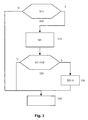
- FIG. 1 shows a block diagram of an apparatus for controlling the Fuel metering and Figures 2 to 4 different Flow diagrams to illustrate the invention Method.
- FIG. 1 the essential elements of a system for Control of fuel metering in an internal combustion engine shown.
- the controller is labeled 100. she applies control signal A to an actuator 110 Furthermore, a pulse wheel 125 is provided, which on the Crank and / or the camshaft is arranged, and by a sensor 120 is scanned, which is connected to the controller 100 connected is. There are also further sensors 130 and 140 provided to generate the signals indicating the operating status the internal combustion engine and ambient conditions characterize.
- the sensor 120 provides pulses in certain Angular positions of the crankshaft and / or camshaft occur.
- the markings on the pulse wheel 125 are preferably arranged such that a Cylinder of the engine an impulse occurs. Furthermore, it can be provided that increment wheels are provided, the pulses with a relatively short distance from deliver approx. 6 °.
- the further sensor 140 delivers a signal M that characterizes the driver's request. This is what it is about preferably a signal that indicates the torque request characterized the internal combustion engine. This size can can also be provided by another control unit.
- Another sensor 130 preferably supplies a signal P, that characterizes the fuel pressure.
- P a signal that characterizes the fuel pressure.
- a so-called common rail system preferably around the rail pressure. Other operating parameters and environmental conditions may vary from those not shown Sensors are detected.
- the controller 100 calculates environmental conditions Control signals A to act upon the actuator 110.
- the control determines the speed N of the internal combustion engine 100 is a quantity representing the amount of fuel to be injected certainly. Furthermore, based on different sizes, such as this amount of fuel to be injected determines a size that determines the start of injection. Next The torque request and the speed can also be more Sizes that reflect the operating status of the vehicle and / or the Characterize the internal combustion engine, are taken into account. Starting from the sizes, the start of injection and the Characterize the amount of fuel to be injected, calculated the controller 100 activates the control signals A of actuator 110.
- the actuator 110 is preferably a Solenoid valve or a so-called piezo actuator. Dependent The actuator 110 takes one from the control signal A. Position that an injection takes place or not he follows. Preferably, a signal is output that the Start of control and a signal indicating the end of control sets.
- the fuel metering of a combustion cycle in one Cylinder is often split into several injections divided up.
- the main injection is characterized by the fact that it is in the Essentially that emitted by the internal combustion engine Characterized moment. It is also possible that the Pre-injection, the main injection or the Post-injection into several pre-injections, Main injections and / or post-injections divided become.
- the procedure according to the invention is described below Example of two pre-injection and the main injection described.
- the procedure according to the invention can, however can also be applied to other partial injections.
- the procedure according to the invention is applicable if at least a first and a second partial injection is carried out.
- the calculation of the Control values for the individual partial injections in different calculation steps can be divided.
- one or more control values one Partial injection calculated. Every partial injection is one Status register assigned which indicates whether a Partial injection is released or not.
- everyone Partial injection is at least one release condition assigned.
- Each release condition is a condition bit in the Status register assigned.
- it contains Status register a release bit for the corresponding Partial injection, this enable bit indicates that the appropriate partial injection may be carried out. in the In the following, the status register is referred to as status.
- the status is in the form of a bit header at which a condition bit for each control value of a partial injection assigned. That each calculation step one Partial injection is a release condition and therefore a Condition bit associated with the status. One of the results Calculation steps that there is an impermissible value, so the condition bit of this release condition that this Calculation step is assigned, reset. this has As a result, the pattern of status no longer matches the certain pattern matches. Is one of these Condition bits reset, this is partial injection not possible.
- the status also contains a bit that indicates that this partial injection due to certain conditions, such as Noise reduction or exhaust gas aftertreatment is desired. Furthermore, the status contains the release bit that indicates whether the injection takes place or is switched off. The The release bit is only set when a Partial injection is desired and possible, that is none of the condition bits are reset. Once one of the Condition bit is reset, there are no further Calculation steps more for this partial injection.
- the status is shown with a predetermined pattern and checked whether the perform further calculations of the calculation step are.
- the Checked release conditions and the condition bit of corresponding release condition set accordingly.
- a first step 200 the Status S of all partial injections with corresponding values busy.
- the bit is set which indicates that this partial injection due to certain conditions, such as for noise reduction or Exhaust gas aftertreatment is desired.
- the status of the unwanted partial injections is filled with the value 0.
- step 210 the various Calculation steps carried out in which the tax values be determined.
- the quantity ME1 which is measured in the first pilot injection VE1, certainly.
- a first query 300 checks whether the status S of the first partial injection with a certain pattern is busy. In the illustrated embodiment provided that it is checked whether the status S with 1 is set. If this is not the case, the program ends in step 340. If the status S is set to 1, i.e. the first pre-injection VE1 is to take place, so in step 310 the amount M1 that occurs during the pilot injection 1 should be measured. Then checked query 320 whether quantity M1 is less than a threshold SW is. This threshold is such that Amounts of fuel below a minimum amount cannot be executed.
- Step 330 the corresponding condition bit in the BS status first pre-injection set to 0.
- Step 340 Recognize the Query 320 that quantity M1 is not less than that Is threshold, the program also ends with step 340th
- step 220 which follows step 210, is the amount M3 of the third pilot injection is calculated. This The calculation is carried out as shown in FIG. 3. Then in step 230, the control duration of the given the first pilot injection 1. this happens corresponding to that described in FIG. 3 Procedure, wherein in step 310 the control period D1 calculated and this in step 320 with a threshold is compared.
- the quantity M2 becomes the second Pre-injection accordingly, as shown in Figure 3 certainly.
- step 250 the Control starts B1, B2 and B3 of the first pilot injection, the second pilot injection and the third pilot injection calculated. If the calculated start of the drive does not are possible, the corresponding condition bit in the status deleted. This is done in accordance with that in FIG. 3 described procedure.
- step 250 the drive durations D2 and D3 the second and third pilot injection.
- the corresponding control periods too small, that too corresponding condition bit in status deleted.
- the calculation is carried out in step 260 the minimum quantity D0 for the main injection. Is the calculated minimum quantity D0 less than a threshold, see above the corresponding condition bit in the status is deleted.
- Step 280 follows the calculation of the minimum quantity D0 for the Main injection depending on the released Pre-injections with pressure wave corrections. Is the calculated minimum quantity less than the threshold, see above the corresponding condition bit is deleted in the status and a loop value SV is set to the value 0, which indicates that the loop is not exited. Is this The loop value is set accordingly Calculation steps 250 to 280 again. Is the Loop value occupied so that it is exited, it is checked in step 290 whether all condition bits and the Bit indicating that this is due to partial injection certain conditions are desired. Is this the case, the release bit is set and then the calculated control values are sent to the control transferred, which converts them into control signals A.
- Step 4 are the calculations of steps 250 through 280 represented by another flowchart.
- First step 400 checks whether a loop value SV is set with 1. If this is the case, the program ends in step 410. If this is not the case, then in Step 420 the calculation of the start of control B1 B2, and B3 of the first, second and third pilot injections. Further the control periods D2 and D3 are calculated. This corresponds essentially to step 250 in FIG Calculation of the individual control values, i.e. of the values B1, B2, B3, D2 and D3 is done in a similar manner to that in Figure 3 illustrated procedure. Doing so will as in step 320 checks whether the start of driving is possible are, i.e.
- step 420 successively for the individual pre-injections the further program steps processed. Are the program steps 430 to 457 for one Partial injection processed. So be for the next one Partial injection again steps 430 to 457 processed. Are these for all partial injections processed again step 400. This is in the embodiment shown by means of a counter K realized.
- step 420 the counter K is incremented by 1.
- the subsequent query 424 checks whether the content of the counter K is greater than TZ.
- TZ is the maximum Number of partial injections. If so, that is steps 430 to 457 are for all partial injections processed, the counter K is reset and that The program continues with step 400. Is the content of the Counter is not greater than TZ, that is, steps 430 to 457 are not yet for all partial injections processed, query 426 checks whether the status the next partial injection to be processed with the certain pattern matches. If this is not the case, then Step 422 follows again. If this is the case, then for this partial injection steps 430 to 457 processed.
- Inquiry 430 checks whether the pilot injection is independent is from the rest of the pre-injections. This means the Query 430 checks for a pressure wave correction is required. This is preferably done from the distance of the partial injections from each other.
- step 445 checks whether this injection quantity is less than is a minimum quantity SW. If this is the case, then in Step 447a set the loop value SV to 0 which indicates that the loop must be recalculated. At the same time in step 447a for this partial injection the corresponding release bit in status S to 0 reset. Is the minimum injection quantity of the Main injection is not less than the threshold, so in step 449a the loop value is set to 1 which indicates that the loop can be left. Subsequently step 422 is performed to calculate the next one Partial injection.
- Step 454 is the calculation of the minimum quantity D0 correspondingly as in step 440. Then the checks Query 456 whether the minimum quantities D0 are less than that Threshold is SW. If this is the case, then corresponding to step 447 as in step 447 Loop variable set to 0 and the status bit to 0. is the value D0 is not less than the threshold value, or is the Status bit not equal to 0, in step 449 the Loop variable SV set to 1.
- Step 449 and 457 follow step 422 to calculate the next partial injection. This means if none Correction of other partial injections and the Minimum quantity D0 for the main injection is reached the loop value is set to such a value that the Loop is exited. This means if there is no correction other partial injections and the minimum quantity D0 is reached for the main injection recalculation of the control values.
- the calculation of the different control values the individual partial injections done in a fixed order is provided that a first set of calculation steps, these are in particular the calculation steps 210 to 240, at the beginning done once. Further calculation steps, these are in particular the calculation steps 250 to 280 however, repeatedly performed.
- the first group of calculation steps is are calculations made by other injections not to be influenced. Tax values by others Calculations are influenced in the second group summarized. One of the control values changes due to a correction, these calculation steps are the other partial injections processed again.
- the structure of the individual calculation steps is right similar and is shown in Figure 3. With everyone The first step in the calculation step is the Status value of the corresponding partial injection. Finally the tax value is calculated. It also takes place a check whether the calculated tax value is a accepted value. Are injection quantities or Driving times calculated, it is checked whether this is greater as a threshold. Will start driving calculated, it is checked whether this is in a permissible Area. If so, i.e. the start of driving lies in a permitted range and the activation duration, or the injection quantity exceeds a threshold value, then the status value is set accordingly that this injection can be done. Are the values inadmissible or less than the threshold value, so becomes the corresponding status value reset.
- the further injection system is activated by means of the release bit informed that this injection is switched off. Based the individual bits can be displayed based on which Condition the corresponding partial injection switched off has been.
Landscapes
- Engineering & Computer Science (AREA)
- Chemical & Material Sciences (AREA)
- Combustion & Propulsion (AREA)
- Mechanical Engineering (AREA)
- General Engineering & Computer Science (AREA)
- Electrical Control Of Air Or Fuel Supplied To Internal-Combustion Engine (AREA)
- Combined Controls Of Internal Combustion Engines (AREA)
Abstract
Description
Claims (10)
- Verfahren zur Steuerung der Kraftstoffzumessung in eine Brennkraftmaschine, bei dem der Kraftstoff mit wenigstens einer ersten und einer zweiten Teileinspritzung zugemessen wird, wobei in wenigstens zwei Berechnungsschritten jeweils wenigstens ein Steuerwert einer Teileinspritzung ermittelt wird, wobei der jeweilige Berechnungsschritt abgearbeitet wird, wenn ein Statusregister ein bestimmtes Muster aufweist.
- Verfahren nach Anspruch 1, dadurch gekennzeichnet, dass die Berechnungsschritte in einer festen Reihenfolge erfolgen.
- Verfahren nach einem der vorhergehenden Ansprüche, dass jeder Teileinspritzung wenigstens ein Bit des Statusregisters zugeordnet ist.
- Verfahren nach einem der vorhergehenden Ansprüche, dass jedem Berechnungsschritt ein Bit des Statusregisters zugeordnet ist.
- Verfahren nach Anspruch 1 oder 2, dadurch gekennzeichnet, dass die Berechnungsschritte die Abfrage des Statusregisters, die Berechnung des Steuerwerts und die Überprüfung, ob das dem Berechnungsschritt zugeordnete Bit des Stautsregisters zu setzen ist, beinhalten.
- Verfahren nach einem der vorhergehenden Ansprüche, dadurch gekennzeichnet, dass wenigstens eine erste Gruppe von Berechnungsschritten einmal durchgeführt werden.
- Verfahren nach einem der vorhergehenden Ansprüche, dadurch gekennzeichnet, dass wenigstens eine zweite Gruppe von Berechnungsschritten wiederholt durchgeführt werden.
- Verfahren nach Anspruch 7, dadurch gekennzeichnet, dass bei einer Änderung des Statusregisters einer Teileinspritzung wenigstens die zweite Gruppe von Berechnungsschritten für die übrigen Teileinspritzungen wiederholt werden.
- Verfahren nach Anspruch 8, dadurch gekennzeichnet, daß sich das Statusregister einer Teileinspritzung ändert, wenn die Steuerwerte unzulässige Werte annehmen.
- Vorrichtung zur Steuerung der Kraftstoffzumessung in eine Brennkraftmaschine, bei dem der Kraftstoff mit wenigstens einer ersten und einer zweiten Teileinspritzung zugemessen wird, mit Mitteln, die in wenigstens zwei Berechnungsschritten jeweils wenigstens ein Steuerwert einer Teileinspritzung ermitteln, wobei der jeweilige Berechnungsschritt abgearbeitet wird, wenn ein Statusregister ein bestimmtes Muster aufweist.
Applications Claiming Priority (2)
| Application Number | Priority Date | Filing Date | Title |
|---|---|---|---|
| DE10141700 | 2001-08-25 | ||
| DE10141700A DE10141700A1 (de) | 2001-08-25 | 2001-08-25 | Verfahren und Vorrichtung zur Steuerung der Kraftstoffzumessung in eine Brennkraftmaschine |
Publications (3)
| Publication Number | Publication Date |
|---|---|
| EP1288474A2 true EP1288474A2 (de) | 2003-03-05 |
| EP1288474A3 EP1288474A3 (de) | 2006-01-18 |
| EP1288474B1 EP1288474B1 (de) | 2008-07-09 |
Family
ID=7696603
Family Applications (1)
| Application Number | Title | Priority Date | Filing Date |
|---|---|---|---|
| EP02016162A Expired - Lifetime EP1288474B1 (de) | 2001-08-25 | 2002-07-20 | Verfahren und Vorrichtung zur Steuerung der Kraftstoffzumessung in eine Brennkraftmaschine |
Country Status (3)
| Country | Link |
|---|---|
| EP (1) | EP1288474B1 (de) |
| JP (1) | JP4072024B2 (de) |
| DE (2) | DE10141700A1 (de) |
Families Citing this family (1)
| Publication number | Priority date | Publication date | Assignee | Title |
|---|---|---|---|---|
| JP2007162585A (ja) * | 2005-12-14 | 2007-06-28 | Nissan Motor Co Ltd | エンジンの燃料噴射制御装置及び燃料噴射制御方法 |
Citations (1)
| Publication number | Priority date | Publication date | Assignee | Title |
|---|---|---|---|---|
| DE19860398A1 (de) | 1998-12-28 | 2000-07-06 | Bosch Gmbh Robert | Verfahren und Vorrichtung zur Steuerung der Kraftstoffzumessung in eine Brennkraftmaschine |
Family Cites Families (4)
| Publication number | Priority date | Publication date | Assignee | Title |
|---|---|---|---|---|
| US5893347A (en) * | 1997-12-18 | 1999-04-13 | Caterpillar Inc. | Method for delivering a small quantity of fuel with a hydraulically-actuated injector during split injection |
| EP0953756B1 (de) * | 1998-04-28 | 2003-12-10 | Toyota Jidosha Kabushiki Kaisha | Kraftstoffeinspritzungssteuerapparat für einen Verbrennungsmotor |
| JP3915329B2 (ja) * | 1999-07-21 | 2007-05-16 | 日産自動車株式会社 | ディーゼルエンジンの燃料噴射制御装置 |
| US6612292B2 (en) * | 2001-01-09 | 2003-09-02 | Nissan Motor Co., Ltd. | Fuel injection control for diesel engine |
-
2001
- 2001-08-25 DE DE10141700A patent/DE10141700A1/de not_active Withdrawn
-
2002
- 2002-07-20 EP EP02016162A patent/EP1288474B1/de not_active Expired - Lifetime
- 2002-07-20 DE DE50212460T patent/DE50212460D1/de not_active Expired - Lifetime
- 2002-08-22 JP JP2002242339A patent/JP4072024B2/ja not_active Expired - Fee Related
Patent Citations (1)
| Publication number | Priority date | Publication date | Assignee | Title |
|---|---|---|---|---|
| DE19860398A1 (de) | 1998-12-28 | 2000-07-06 | Bosch Gmbh Robert | Verfahren und Vorrichtung zur Steuerung der Kraftstoffzumessung in eine Brennkraftmaschine |
Also Published As
| Publication number | Publication date |
|---|---|
| JP2003097331A (ja) | 2003-04-03 |
| EP1288474B1 (de) | 2008-07-09 |
| JP4072024B2 (ja) | 2008-04-02 |
| DE10141700A1 (de) | 2003-03-06 |
| EP1288474A3 (de) | 2006-01-18 |
| DE50212460D1 (de) | 2008-08-21 |
Similar Documents
| Publication | Publication Date | Title |
|---|---|---|
| DE19945618B4 (de) | Verfahren und Vorrichtung zur Steuerung eines Kraftstoffzumeßsystems einer Brennkraftmaschine | |
| EP0940571B1 (de) | Verfahren und Vorrichtung zum Steuern der Kraftstoffeinspritzung | |
| DE102007053406B3 (de) | Verfahren und Vorrichtung zur Durchführung sowohl einer Adaption wie einer Diagnose bei emissionsrelevanten Steuereinrichtungen in einem Fahrzeug | |
| EP1526267A2 (de) | Verfahren zur Driftkompensation eines Injektors für die direkte Kraftstoffeinspritzung in einen Zylinder einer Brennkraftmaschine sowie Vorrichtung | |
| DE3403260C2 (de) | ||
| EP1495222A1 (de) | Verfahren zum berwachen einer brennkraftmaschine | |
| DE19931823B4 (de) | Verfahren und Vorrichtung zur Steuerung einer Brennkraftmaschine | |
| EP1347165B1 (de) | Verfahren und Vorrichtung zur Steuerung der Kraftstoffzumessung in eine Brennkraftmaschine | |
| EP0818619B1 (de) | Verfahren und Vorrichtung zur Überwachung der Stellung einer variablen Ventilsteuerung | |
| EP1309781B1 (de) | Verfahren und vorrichtung zur steuerung einer brennkraftmaschine | |
| DE19860398B4 (de) | Verfahren und Vorrichtung zur Steuerung der Kraftstoffzumessung in eine Brennkraftmaschine | |
| EP1712768A2 (de) | Verfahren und Vorrichtung zur Steuerung der Kraftstoffzumessung in wenigstens einen Brennraum einer Brennkraftmaschine | |
| DE19728841C2 (de) | Verfahren und Vorrichtung zur Überwachung einer Datenübertragung in einem Kraftfahrzeug | |
| EP1288474B1 (de) | Verfahren und Vorrichtung zur Steuerung der Kraftstoffzumessung in eine Brennkraftmaschine | |
| DE4322270A1 (de) | Verfahren und Vorrichtung zur Steuerung einer Brennkraftmaschine | |
| DE102006001368B4 (de) | Verfahren und Vorrichtung zur Steuerung einer Brennkraftmaschine | |
| EP0898068B1 (de) | Verfahren und Vorrichtung zur Steuerung der Kraftstoff-Einspritzmenge für eine Brennkraftmaschine in einem Fahrzeug | |
| EP1029168B1 (de) | Verfahren zum betreiben einer brennkraftmaschine insbesondere eines kraftfahrzeugs | |
| EP1134390A2 (de) | Verfahren und Vorrichtung zur Steuerung einer Brennkraftmaschine | |
| EP1045125B1 (de) | Verfahren und Vorrichtung zur Steuerung einer Brennkraftmaschine | |
| DE10041442B4 (de) | Verfahren und Vorrichtung zur Steuerung der Kraftstoffzumessung in eine Brennkraftmaschine | |
| DE102005047350A1 (de) | Verfahren und Vorrichtung zur Steuerung einer Brennkraftmaschine | |
| DE102006044771B4 (de) | Verfahren und Steuergerät zur Bestimmung eines Fehlers einer Einspritzmenge eines mit einer Ansteuerdauer angesteuerten Einspritzstellgliedes eines Verbrennungsmotors | |
| EP1554482A1 (de) | Verfahren und vorrichtung zur steuerung einer brennkraftmaschine | |
| WO2013000937A2 (de) | Verfahren und system zur steuerung eines kraftstoffinjektorsystems |
Legal Events
| Date | Code | Title | Description |
|---|---|---|---|
| PUAI | Public reference made under article 153(3) epc to a published international application that has entered the european phase |
Free format text: ORIGINAL CODE: 0009012 |
|
| AK | Designated contracting states |
Kind code of ref document: A2 Designated state(s): AT BE BG CH CY CZ DE DK EE ES FI FR GB GR IE IT LI LU MC NL PT SE SK TR |
|
| AX | Request for extension of the european patent |
Extension state: AL LT LV MK RO SI |
|
| PUAL | Search report despatched |
Free format text: ORIGINAL CODE: 0009013 |
|
| AK | Designated contracting states |
Kind code of ref document: A3 Designated state(s): AT BE BG CH CY CZ DE DK EE ES FI FR GB GR IE IT LI LU MC NL PT SE SK TR |
|
| AX | Request for extension of the european patent |
Extension state: AL LT LV MK RO SI |
|
| 17P | Request for examination filed |
Effective date: 20060718 |
|
| AKX | Designation fees paid |
Designated state(s): DE FR GB |
|
| 17Q | First examination report despatched |
Effective date: 20060926 |
|
| GRAP | Despatch of communication of intention to grant a patent |
Free format text: ORIGINAL CODE: EPIDOSNIGR1 |
|
| GRAS | Grant fee paid |
Free format text: ORIGINAL CODE: EPIDOSNIGR3 |
|
| GRAA | (expected) grant |
Free format text: ORIGINAL CODE: 0009210 |
|
| AK | Designated contracting states |
Kind code of ref document: B1 Designated state(s): DE FR GB |
|
| REG | Reference to a national code |
Ref country code: GB Ref legal event code: FG4D Free format text: NOT ENGLISH |
|
| REF | Corresponds to: |
Ref document number: 50212460 Country of ref document: DE Date of ref document: 20080821 Kind code of ref document: P |
|
| PLBE | No opposition filed within time limit |
Free format text: ORIGINAL CODE: 0009261 |
|
| STAA | Information on the status of an ep patent application or granted ep patent |
Free format text: STATUS: NO OPPOSITION FILED WITHIN TIME LIMIT |
|
| 26N | No opposition filed |
Effective date: 20090414 |
|
| REG | Reference to a national code |
Ref country code: FR Ref legal event code: PLFP Year of fee payment: 15 |
|
| PGFP | Annual fee paid to national office [announced via postgrant information from national office to epo] |
Ref country code: GB Payment date: 20160722 Year of fee payment: 15 Ref country code: DE Payment date: 20160927 Year of fee payment: 15 |
|
| PGFP | Annual fee paid to national office [announced via postgrant information from national office to epo] |
Ref country code: FR Payment date: 20160722 Year of fee payment: 15 |
|
| REG | Reference to a national code |
Ref country code: DE Ref legal event code: R119 Ref document number: 50212460 Country of ref document: DE |
|
| GBPC | Gb: european patent ceased through non-payment of renewal fee |
Effective date: 20170720 |
|
| REG | Reference to a national code |
Ref country code: FR Ref legal event code: ST Effective date: 20180330 |
|
| PG25 | Lapsed in a contracting state [announced via postgrant information from national office to epo] |
Ref country code: GB Free format text: LAPSE BECAUSE OF NON-PAYMENT OF DUE FEES Effective date: 20170720 Ref country code: DE Free format text: LAPSE BECAUSE OF NON-PAYMENT OF DUE FEES Effective date: 20180201 |
|
| PG25 | Lapsed in a contracting state [announced via postgrant information from national office to epo] |
Ref country code: FR Free format text: LAPSE BECAUSE OF NON-PAYMENT OF DUE FEES Effective date: 20170731 |