EP1287906A2 - Coating apparatus - Google Patents
Coating apparatus Download PDFInfo
- Publication number
- EP1287906A2 EP1287906A2 EP02018261A EP02018261A EP1287906A2 EP 1287906 A2 EP1287906 A2 EP 1287906A2 EP 02018261 A EP02018261 A EP 02018261A EP 02018261 A EP02018261 A EP 02018261A EP 1287906 A2 EP1287906 A2 EP 1287906A2
- Authority
- EP
- European Patent Office
- Prior art keywords
- edge
- coating
- support member
- flexible tape
- coating apparatus
- Prior art date
- Legal status (The legal status is an assumption and is not a legal conclusion. Google has not performed a legal analysis and makes no representation as to the accuracy of the status listed.)
- Withdrawn
Links
- 239000011248 coating agent Substances 0.000 title claims abstract description 86
- 238000000576 coating method Methods 0.000 title claims abstract description 47
- 239000007788 liquid Substances 0.000 description 8
- 239000011247 coating layer Substances 0.000 description 5
- XEEYBQQBJWHFJM-UHFFFAOYSA-N Iron Chemical compound [Fe] XEEYBQQBJWHFJM-UHFFFAOYSA-N 0.000 description 4
- 230000000694 effects Effects 0.000 description 4
- 238000000034 method Methods 0.000 description 4
- 239000000956 alloy Substances 0.000 description 3
- 229910045601 alloy Inorganic materials 0.000 description 3
- 239000000919 ceramic Substances 0.000 description 3
- 230000007423 decrease Effects 0.000 description 2
- 238000010586 diagram Methods 0.000 description 2
- 229910052742 iron Inorganic materials 0.000 description 2
- 239000010410 layer Substances 0.000 description 2
- 239000000843 powder Substances 0.000 description 2
- 230000001105 regulatory effect Effects 0.000 description 2
- 230000002411 adverse Effects 0.000 description 1
- 238000004140 cleaning Methods 0.000 description 1
- 230000001771 impaired effect Effects 0.000 description 1
- 239000000463 material Substances 0.000 description 1
Images

Classifications
-
- B—PERFORMING OPERATIONS; TRANSPORTING
- B05—SPRAYING OR ATOMISING IN GENERAL; APPLYING FLUENT MATERIALS TO SURFACES, IN GENERAL
- B05C—APPARATUS FOR APPLYING FLUENT MATERIALS TO SURFACES, IN GENERAL
- B05C5/00—Apparatus in which liquid or other fluent material is projected, poured or allowed to flow on to the surface of the work
- B05C5/02—Apparatus in which liquid or other fluent material is projected, poured or allowed to flow on to the surface of the work the liquid or other fluent material being discharged through an outlet orifice by pressure, e.g. from an outlet device in contact or almost in contact, with the work
-
- B—PERFORMING OPERATIONS; TRANSPORTING
- B05—SPRAYING OR ATOMISING IN GENERAL; APPLYING FLUENT MATERIALS TO SURFACES, IN GENERAL
- B05C—APPARATUS FOR APPLYING FLUENT MATERIALS TO SURFACES, IN GENERAL
- B05C9/00—Apparatus or plant for applying liquid or other fluent material to surfaces by means not covered by any preceding group, or in which the means of applying the liquid or other fluent material is not important
- B05C9/06—Apparatus or plant for applying liquid or other fluent material to surfaces by means not covered by any preceding group, or in which the means of applying the liquid or other fluent material is not important for applying two different liquids or other fluent materials, or the same liquid or other fluent material twice, to the same side of the work
-
- B—PERFORMING OPERATIONS; TRANSPORTING
- B05—SPRAYING OR ATOMISING IN GENERAL; APPLYING FLUENT MATERIALS TO SURFACES, IN GENERAL
- B05C—APPARATUS FOR APPLYING FLUENT MATERIALS TO SURFACES, IN GENERAL
- B05C5/00—Apparatus in which liquid or other fluent material is projected, poured or allowed to flow on to the surface of the work
- B05C5/02—Apparatus in which liquid or other fluent material is projected, poured or allowed to flow on to the surface of the work the liquid or other fluent material being discharged through an outlet orifice by pressure, e.g. from an outlet device in contact or almost in contact, with the work
- B05C5/0254—Coating heads with slot-shaped outlet
Definitions
- the present invention relates to a coating apparatus for coating a thin layer of A coating agent on a running flexible tape support member.
- the present invention particularly relates to a coating head for ejecting the coating agent.
- a coating head for forming a thin coating layer As a coating head for forming a thin coating layer, a structure such as disclosed in Japanese Unexamined Patent Application, First Publication No. Sho 62-241574 (hereinafter called first prior art) is generally known. As shown in FIG. 5, a coating head 5 has two parallel members 1, 2. Between the parallel members 1, 2, a slot 3 is formed. At both ends in the longitudinal direction of the slot 3, regulating members 4, 4 are disposed for regulating the width of the slot 3.
- the coating head 5 having such a structure, when a long wide flexible tape support member 6 runs on the tips of parallel edge members in the direction indicated by arrow A in the drawing, a coating agent is ejected from the slot 3 toward the flexible tape support member 6; thus, the coating agent is coated on one surface of the flexible tape support member 6 at a uniform thickness.
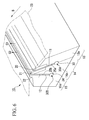
- FIG. 6 A coating apparatus having more than two slots so as to coat a plurality of coating layers is shown in FIG. 6 (hereinafter called second prior art).
- the coating apparatus shown as the second prior art is provided with a coating head for coating a coating agent on the long wide running flexible tape support member as shown in FIG. 6.
- the coating head 10 has three edge units, i. e., a first edge unit 13, a second edge unit 14, and a third edge unit 15, which are disposed in this order in the running direction (indicated by arrow B in the drawing) of a flexible tape support member 23.
- a first slot 11 is formed between the first edge unit 13 and the second edge unit 14, and a second slot 12 is formed between the second edge unit 14 and the third edge unit 15 such that the coating agent flows toward the flexible tape support member 23.
- first, second, and third edge units 13, 14, and 15 comprise a first, second, and third edge supporting members 13a, 14a, and 15a which are made of an iron-based alloy and first, second, and third edges 20, 21, and 22 which are made of a cemented carbide alloy and attached to the tips of the first, second, and third edge supporting members 13a, 14a, and 15a facing to the flexible tape support member 23 press against the flexible tape support member 23.
- the coating apparatus has a coating agent supply device, which is not shown in the drawing for supplying coating agents 30A and 30B.
- the coating agents 30A and 30B are pumped through pockets 33, 34, the first slot 11, and the second slot 12, and pushed out of each outlet of the first and the second slots 11, 12 to be ejected in the directions indicated by arrows C1 and C2.
- the coating agents 30A and 30B are layered on one surface of the flexible tape support member 23 which is fed by a feeding device, not shown in the drawing, in the direction indicated by arrow B.
- the thickness of the coating agent which is coated on the flexible tape support member is several microns to several tens microns; therefore, the width of the slots in which the coating agents flow tends to be narrow.
- a coating agent flows through such a slot, quite a large amount of friction occurs between the coating agent and the slot.
- the slot surface of the edge supporting member is subjected to polish finishing.
- edges 42, 43 are fixed on edge supporting members 40, 41 by edge fixing members 44a, 44b disposed on side surfaces 47, 48 which are on the opposite sides of edge supporting members 40, 41 with respect to slot surfaces 46a, 46b.
- the present invention was made in consideration of the above-mentioned problem.
- the object of the present invention is to provide a coating apparatus in which an edge made of a hard material such as cemented carbide can be fixed rigidly without any adverse effect on the flatness of the slot surfaces.
- the coating apparatus according to the present invention has the following structure.
- the coating apparatus has a coating head for coating a coating agent on a flexible tape support member which runs in one direction.
- the coating head has a plurality of edge units which are disposed in the running direction of the flexible tape support member. Slots for passing the coating agent toward the flexible tape support member are formed between the edge units.
- Edge units comprise edge support members and edges which are attached to the tips of the edge support members so as to slide on the flexible tape support member. Among the edges, at least the edge which is not disposed at both ends in the running direction of the flexible tape support member is fixed to the edge support member by an edge fixing member which is inserted in the direction from the bottom portion of the coating apparatus toward the edge.
- the flatness of the slot surfaces is not deteriorated by the edge fixing member for fixing the edges to the edge supporting members. Therefore, the friction of the coating agent is prevented from increasing. Liquid pressure deviations during the ejection of the coating agent are suppressed, and the post-coating thickness of the coating layer can be controlled uniformly.
- the coating agent becomes more separable from the slots.
- it is possible to prevent the coating agent from becoming hard and adhering to the slot surfaces.
- Such improvements helps in the cleaning of the slots for maintaining the coating apparatus.
- the edge is fixed in a state in which it is pulled into a recessed section provided at the tip of the edge support member by the edge fixing member.
- the edge is fixed rigidly by utilizing wedge effect; thus, backlash of the edge is effectively restrained.
- the flatness of the slot surfaces can be improved by using such a structure. Also, liquid pressure deviations during the ejection of the coating agent can be suppressed effectively over a long period of time.
- the present invention among the edges, at least the edge which is not disposed at both ends in the running direction of the flexible tape support member is fixed to the edge support member by the edge fixing member which is inserted in the direction from the bottom portion of the coating apparatus toward the edge. Therefore, the flatness of the surfaces forming the slots is not deteriorated.
- friction during the ejection of the coating agent decreases, thus, liquid pressure deviations can be suppressed. Therefore, it is possible to form multiple layers at a uniform thickness.
- the edge is fixed in a state in which it is pulled into a recessed section provided at the tip of the edge support member by the edge fixing member. Therefore, the edge is fixed to the edge supporting member rigidly by a wedge effect. Thus, the backlash of the edge is restrained, and the flatness of the slot surfaces of the slot can be maintained for a long period of time. Also, it is possible to form multiple layers at a uniform thickness for a long period of time.
- the present invention relates to a coating apparatus for uniformly coating surfaces of a flexible tape support member such as a film and a sheet running in one direction, by a coating agent so as to form a thin coated layer
- a coating apparatus for uniformly coating surfaces of a flexible tape support member such as a film and a sheet running in one direction, by a coating agent so as to form a thin coated layer
- the specific structural and functional details disclosed herein are merely representative and do not limit the scope of the present invention.
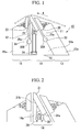
- FIG. 1 An embodiment of the coating apparatus according to the present invention is shown in FIG. 1.
- the coating apparatus has a coating head 10.
- a first slot (slot) 11 which is formed between a first edge unit 13 and a second edge unit 14, and a second slot (slot) 12, which is formed between the second edge unit 14 and a third edge unit 15, are formed.
- the first, second, and third edge units 13, 14, and 15 are disposed in this order in the running direction indicated by arrow A of a flexible tape support member 23.
- First, second, and third edges 20, 21, and 22 made of cemented carbide are attached to the tips of the first, second, and third edge supporting members (edge supporting members) 13a, 14a, and 15a made of iron-based alloy.
- coating agents 30A, 30B are supplied by a coating agent supplying device, which is not shown in the drawing, while the flexible tape support member 23 is running.
- the coating agents 30A, 30B pass through pockets 33, 34, the first slot 11, and the second slot 12; thus, the coating agents 30a, 30B are layered on one surface of the flexible tape support member 23.
- the coating agent is applied to form a base member of a green sheet for a layered ceramics condenser.
- the coating agent is made of a liquid containing a dielectric ceramic powder and a liquid containing a dielectric component which is somewhat different from the above-mentioned dielectric ceramic powder.
- the second edge unit 14 is structured such that both sides of the second edge 21 from slot surfaces 25a, 25b which are disposed on the outside of the edge unit 14, and a clamping bolt 24 (fixing member) is inserted in a bottom portion 32 of the second edge supporting member 14a; thus, the second edge 21 is fixed on the second edge supporting member 14a.
- FIG. 2 shows the detailed structure of the second edge unit 14.
- a recessed section 30 is formed on the tip of the second edge supporting member 14a, and the second edge 21 is disposed in the recessed section 30.
- the second edge 21 is fixed such that the second edge 21 is pulled into the recessed section 30 by the clamp bolt 24 so as to be fixed to the second edge supporting member 14a.
- the second edge 21 is rigidly fixed to the second edge supporting member 14a by a wedge effect caused by being pushed against mutually perpendicular surfaces 31a, 31b in the recessed section 30.
- the backlash of the second edge 21 is restrained effectively.
- the flatness can be maintained.
- liquid pressure deviations during the ejection of the coating agent are suppressed for a long period of time, and furthermore, the forming of multiple layers at a uniform thickness can be realized.
- three edge units 13, 14, and 15 are employed so as to form two thin coating layers on the flexible tape support member 23, however, it is acceptable if more than three coating agents are applied to the flexible tape support member 23. As long as the fixing method for fixing the edge having slot surfaces on both sides of the edge remains unchanged, a structure having more than three edge units for the coating head is acceptable.
Landscapes
- Coating Apparatus (AREA)
Abstract
Description
- The present invention relates to a coating apparatus for coating a thin layer of A coating agent on a running flexible tape support member. The present invention particularly relates to a coating head for ejecting the coating agent.
- As a coating head for forming a thin coating layer, a structure such as disclosed in Japanese Unexamined Patent Application, First Publication No. Sho 62-241574 (hereinafter called first prior art) is generally known. As shown in FIG. 5, a
coating head 5 has twoparallel members 1, 2. Between theparallel members 1, 2, aslot 3 is formed. At both ends in the longitudinal direction of theslot 3, regulatingmembers slot 3. - In the
coating head 5 having such a structure, when a long wide flexibletape support member 6 runs on the tips of parallel edge members in the direction indicated by arrow A in the drawing, a coating agent is ejected from theslot 3 toward the flexibletape support member 6; thus, the coating agent is coated on one surface of the flexibletape support member 6 at a uniform thickness. - A coating apparatus having more than two slots so as to coat a plurality of coating layers is shown in FIG. 6 (hereinafter called second prior art).
- The coating apparatus shown as the second prior art is provided with a coating head for coating a coating agent on the long wide running flexible tape support member as shown in FIG. 6. As shown in the drawing, the
coating head 10 has three edge units, i. e., afirst edge unit 13, asecond edge unit 14, and athird edge unit 15, which are disposed in this order in the running direction (indicated by arrow B in the drawing) of a flexibletape support member 23. Afirst slot 11 is formed between thefirst edge unit 13 and thesecond edge unit 14, and asecond slot 12 is formed between thesecond edge unit 14 and thethird edge unit 15 such that the coating agent flows toward the flexibletape support member 23. - These first, second, and
third edge units edge supporting members third edges edge supporting members tape support member 23 press against the flexibletape support member 23. - The coating apparatus has a coating agent supply device, which is not shown in the drawing for supplying
coating agents coating agents pockets first slot 11, and thesecond slot 12, and pushed out of each outlet of the first and thesecond slots coating agents tape support member 23 which is fed by a feeding device, not shown in the drawing, in the direction indicated by arrow B. - Here, the thickness of the coating agent which is coated on the flexible tape support member is several microns to several tens microns; therefore, the width of the slots in which the coating agents flow tends to be narrow. When a coating agent flows through such a slot, quite a large amount of friction occurs between the coating agent and the slot. Thus, there is a problem in that it is difficult to control the post-coating thickness of the coating agent uniformly because liquid pressure deviations occur in the coating agent when the friction becomes larger than required.
- Therefore, from a design point of view for removing bumps on the slot surface as much as possible so as to decrease such friction, the slot surface of the edge supporting member is subjected to polish finishing.
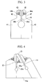
- As shown in FIG. 3, when making the constitution of the first prior art,
edges edge supporting members edge fixing members side surfaces edge supporting members slot surfaces - However, when making the constitution of the second prior art both surfaces of the
second edge 21 fromslot surfaces slots edge 21 is fixed to the secondedge supporting member 14a by the same fixing method as that of the first prior art, the flatness of theslot surfaces - The present invention was made in consideration of the above-mentioned problem. The object of the present invention is to provide a coating apparatus in which an edge made of a hard material such as cemented carbide can be fixed rigidly without any adverse effect on the flatness of the slot surfaces.
- In order to solve the above-mentioned problem, the coating apparatus according to the present invention has the following structure.
- The coating apparatus has a coating head for coating a coating agent on a flexible tape support member which runs in one direction. The coating head has a plurality of edge units which are disposed in the running direction of the flexible tape support member. Slots for passing the coating agent toward the flexible tape support member are formed between the edge units. Edge units comprise edge support members and edges which are attached to the tips of the edge support members so as to slide on the flexible tape support member. Among the edges, at least the edge which is not disposed at both ends in the running direction of the flexible tape support member is fixed to the edge support member by an edge fixing member which is inserted in the direction from the bottom portion of the coating apparatus toward the edge.
- In such a structure, the flatness of the slot surfaces is not deteriorated by the edge fixing member for fixing the edges to the edge supporting members. Therefore, the friction of the coating agent is prevented from increasing. Liquid pressure deviations during the ejection of the coating agent are suppressed, and the post-coating thickness of the coating layer can be controlled uniformly.
- Furthermore, as the flatness of the slot surfaces improves, the coating agent becomes more separable from the slots. Thus, it is possible to prevent the coating agent from becoming hard and adhering to the slot surfaces. Such improvements helps in the cleaning of the slots for maintaining the coating apparatus.
- Also, in the present invention, the edge is fixed in a state in which it is pulled into a recessed section provided at the tip of the edge support member by the edge fixing member.
- In such a structure, the edge is fixed rigidly by utilizing wedge effect; thus, backlash of the edge is effectively restrained. The flatness of the slot surfaces can be improved by using such a structure. Also, liquid pressure deviations during the ejection of the coating agent can be suppressed effectively over a long period of time.
- As explained above, by the present invention, among the edges, at least the edge which is not disposed at both ends in the running direction of the flexible tape support member is fixed to the edge support member by the edge fixing member which is inserted in the direction from the bottom portion of the coating apparatus toward the edge. Therefore, the flatness of the surfaces forming the slots is not deteriorated. By such a structure, friction during the ejection of the coating agent decreases, thus, liquid pressure deviations can be suppressed. Therefore, it is possible to form multiple layers at a uniform thickness.
- Also, the edge is fixed in a state in which it is pulled into a recessed section provided at the tip of the edge support member by the edge fixing member. Therefore, the edge is fixed to the edge supporting member rigidly by a wedge effect. Thus, the backlash of the edge is restrained, and the flatness of the slot surfaces of the slot can be maintained for a long period of time. Also, it is possible to form multiple layers at a uniform thickness for a long period of time.
-
- FIG. 1 is a cross section of a coating head.
- FIG. 2 a cross section showing the details of the coating head.
- FIG. 3 is a schematic diagram showing a method for attaching an edge when there is one slot.
- FIG. 4 is a schematic diagram showing a method for attaching an edge when there are two slots.
- FIG. 5 is a perspective view of a conventional coating apparatus having one slot.
- FIG. 6 is a perspective view of a conventional coating apparatus having two slots.
-
- Embodiments of the coating apparatus according to the present invention are explained as follows with reference to the drawings. Although the present invention relates to a coating apparatus for uniformly coating surfaces of a flexible tape support member such as a film and a sheet running in one direction, by a coating agent so as to form a thin coated layer, the specific structural and functional details disclosed herein are merely representative and do not limit the scope of the present invention.
- An embodiment of the coating apparatus according to the present invention is shown in FIG. 1. In FIG. 1, the coating apparatus has a
coating head 10. In thecoating head 10, a first slot (slot) 11, which is formed between afirst edge unit 13 and asecond edge unit 14, and a second slot (slot) 12, which is formed between thesecond edge unit 14 and athird edge unit 15, are formed. The first, second, andthird edge units tape support member 23. First, second, andthird edges - In the coating apparatus,
coating agents tape support member 23 is running. Thecoating agents pockets first slot 11, and thesecond slot 12; thus, thecoating agents 30a, 30B are layered on one surface of the flexibletape support member 23. - In the present embodiment, the coating agent is applied to form a base member of a green sheet for a layered ceramics condenser. The coating agent is made of a liquid containing a dielectric ceramic powder and a liquid containing a dielectric component which is somewhat different from the above-mentioned dielectric ceramic powder.
- As shown in FIG. 1, the
second edge unit 14 is structured such that both sides of thesecond edge 21 fromslot surfaces edge unit 14, and a clamping bolt 24 (fixing member) is inserted in abottom portion 32 of the secondedge supporting member 14a; thus, thesecond edge 21 is fixed on the secondedge supporting member 14a. - By such a structure, it is not necessary that the
clamp bolt 24 be disposed on the slot surfaces 25a, 25b; thus, the slot surfaces 25a, 25b can be made flat. Therefore, it is possible to prevent the friction of the coating agent from increasing, and also liquid pressure deviations during the ejection of the coating agent are suppressed; thus, it is possible to obtain a uniform thickness of the multiple layers. - Furthermore, FIG. 2 shows the detailed structure of the
second edge unit 14. In thesecond edge unit 14, a recessedsection 30 is formed on the tip of the secondedge supporting member 14a, and thesecond edge 21 is disposed in the recessedsection 30. Thesecond edge 21 is fixed such that thesecond edge 21 is pulled into the recessedsection 30 by theclamp bolt 24 so as to be fixed to the secondedge supporting member 14a. - By such a structure, the
second edge 21 is rigidly fixed to the secondedge supporting member 14a by a wedge effect caused by being pushed against mutuallyperpendicular surfaces section 30. Thus, the backlash of thesecond edge 21 is restrained effectively. Also, in connecting portions between thesecond edge 21 and the secondedge supporting member 14a, the flatness can be maintained. Thus, liquid pressure deviations during the ejection of the coating agent are suppressed for a long period of time, and furthermore, the forming of multiple layers at a uniform thickness can be realized. - In the present embodiment of the coating apparatus, three
edge units tape support member 23, however, it is acceptable if more than three coating agents are applied to the flexibletape support member 23. As long as the fixing method for fixing the edge having slot surfaces on both sides of the edge remains unchanged, a structure having more than three edge units for the coating head is acceptable.
Claims (4)
- A coating apparatus having a coating head for applying a coating agent on a flexible tape support member (23) which runs in one direction wherein
the coating head (10) has a plurality of edges (21, 22, 23) which are disposed in the running direction (A) of the flexible tape suppbrt member (23); and
slots (11,12) for passing the coating agent toward the flexible tape support member (23) are formed between the edge units. - A coating apparatus according to claim 1 wherein the edge units comprise edge support members (13a, 14a, 15a) and edges (20, 21, 22) which are attached to a tip of the edge support member so as to slide on the flexible tape support member (23).
- A coating apparatus according to claim 1 wherein, among the edges, at least the edge (21) which is not disposed at both ends in the running direction of the flexible tape support member is fixed to the edge support member (14a) by an edge fixing member (24) which is inserted in a direction from a bottom portion of the coating apparatus toward the edge (21).
- A coating apparatus according to claim 1 wherein the edge (21) is fixed so as to be pulled into a recessed section (30) formed on the edge support member (14a) by the edge fixing member (24).
Applications Claiming Priority (4)
| Application Number | Priority Date | Filing Date | Title |
|---|---|---|---|
| JP2001254763 | 2001-08-24 | ||
| JP2001254763 | 2001-08-24 | ||
| JP2001388530A JP3823820B2 (en) | 2001-08-24 | 2001-12-20 | Coating device |
| JP2001388530 | 2001-12-20 |
Publications (2)
| Publication Number | Publication Date |
|---|---|
| EP1287906A2 true EP1287906A2 (en) | 2003-03-05 |
| EP1287906A3 EP1287906A3 (en) | 2005-12-21 |
Family
ID=26620950
Family Applications (1)
| Application Number | Title | Priority Date | Filing Date |
|---|---|---|---|
| EP02018261A Withdrawn EP1287906A3 (en) | 2001-08-24 | 2002-08-22 | Coating apparatus |
Country Status (6)
| Country | Link |
|---|---|
| US (1) | US6746537B2 (en) |
| EP (1) | EP1287906A3 (en) |
| JP (1) | JP3823820B2 (en) |
| KR (1) | KR100867908B1 (en) |
| CN (1) | CN1281336C (en) |
| TW (1) | TW572793B (en) |
Cited By (1)
| Publication number | Priority date | Publication date | Assignee | Title |
|---|---|---|---|---|
| WO2007024190A1 (en) * | 2005-08-26 | 2007-03-01 | Akzo Nobel Coatings International Bv | Apparatus and method for dispensing liquids |
Families Citing this family (8)
| Publication number | Priority date | Publication date | Assignee | Title |
|---|---|---|---|---|
| JP3501159B1 (en) * | 2003-04-23 | 2004-03-02 | 三菱マテリアル株式会社 | Application tool and application device |
| CN100473467C (en) * | 2003-07-02 | 2009-04-01 | 三菱麻铁里亚尔株式会社 | Coating tool |
| KR100628275B1 (en) * | 2004-11-04 | 2006-09-27 | 엘지.필립스 엘시디 주식회사 | Printing nozzle |
| JP4492374B2 (en) * | 2005-02-02 | 2010-06-30 | 三菱マテリアル株式会社 | Application tool |
| CN102221784B (en) * | 2010-04-19 | 2013-07-24 | 北京京东方光电科技有限公司 | Glue coating device and glue coating method |
| JP5346972B2 (en) * | 2011-03-30 | 2013-11-20 | 富士フイルム株式会社 | Method for producing film with coating |
| DE102012010050A1 (en) * | 2012-05-22 | 2013-11-28 | Andritz Küsters Gmbh | Cascade nozzle for applying several layers |
| JP6924421B2 (en) * | 2019-09-27 | 2021-08-25 | 株式会社タンガロイ | Coating equipment |
Citations (1)
| Publication number | Priority date | Publication date | Assignee | Title |
|---|---|---|---|---|
| JPS62241574A (en) | 1986-04-10 | 1987-10-22 | Fuji Photo Film Co Ltd | Coating head |
Family Cites Families (11)
| Publication number | Priority date | Publication date | Assignee | Title |
|---|---|---|---|---|
| US3151356A (en) * | 1961-08-02 | 1964-10-06 | Du Pont | Extrusion die |
| DE2228685C3 (en) * | 1972-06-13 | 1978-04-06 | Escher Wyss Gmbh, 7980 Ravensburg | Coating device |
| JPH0677712B2 (en) | 1986-09-30 | 1994-10-05 | 富士写真フイルム株式会社 | Coating device |
| JPS6477875A (en) * | 1987-09-18 | 1989-03-23 | Hitachi Ltd | Fuel concentration sensor of fuel cell |
| US5275660A (en) * | 1988-09-08 | 1994-01-04 | Fuji Photo Film Co., Ltd. | Low mass, thermally stable coating apparatus |
| US5067432A (en) * | 1990-05-23 | 1991-11-26 | Extrusion Dies, Inc. | Replaceable wiping insert for slot die head |
| DE69224881T2 (en) * | 1991-11-06 | 1998-08-27 | Konishiroku Photo Ind | Extrusion type coating device and coating method |
| JP3322720B2 (en) * | 1993-04-20 | 2002-09-09 | 富士写真フイルム株式会社 | Application method |
| JPH0985149A (en) * | 1995-09-25 | 1997-03-31 | Sony Corp | Coating device |
| US6410094B2 (en) * | 1998-02-19 | 2002-06-25 | Fuji Photo Film Co., Ltd. | Extrusion coating head and coating method for flexible support |
| US6033723A (en) * | 1998-02-24 | 2000-03-07 | Imation Corp. | Method and apparatus for coating plurality of wet layers on flexible elongated web |
-
2001
- 2001-12-20 JP JP2001388530A patent/JP3823820B2/en not_active Expired - Lifetime
-
2002
- 2002-08-19 US US10/224,196 patent/US6746537B2/en not_active Expired - Lifetime
- 2002-08-22 EP EP02018261A patent/EP1287906A3/en not_active Withdrawn
- 2002-08-23 TW TW91119170A patent/TW572793B/en not_active IP Right Cessation
- 2002-08-23 CN CNB021301891A patent/CN1281336C/en not_active Expired - Lifetime
- 2002-08-23 KR KR1020020050152A patent/KR100867908B1/en not_active Expired - Lifetime
Patent Citations (1)
| Publication number | Priority date | Publication date | Assignee | Title |
|---|---|---|---|---|
| JPS62241574A (en) | 1986-04-10 | 1987-10-22 | Fuji Photo Film Co Ltd | Coating head |
Cited By (1)
| Publication number | Priority date | Publication date | Assignee | Title |
|---|---|---|---|---|
| WO2007024190A1 (en) * | 2005-08-26 | 2007-03-01 | Akzo Nobel Coatings International Bv | Apparatus and method for dispensing liquids |
Also Published As
| Publication number | Publication date |
|---|---|
| TW572793B (en) | 2004-01-21 |
| US20030037728A1 (en) | 2003-02-27 |
| US6746537B2 (en) | 2004-06-08 |
| KR100867908B1 (en) | 2008-11-10 |
| JP2003136006A (en) | 2003-05-13 |
| CN1411915A (en) | 2003-04-23 |
| KR20030017426A (en) | 2003-03-03 |
| JP3823820B2 (en) | 2006-09-20 |
| EP1287906A3 (en) | 2005-12-21 |
| CN1281336C (en) | 2006-10-25 |
Similar Documents
| Publication | Publication Date | Title |
|---|---|---|
| JP3220265B2 (en) | Coating equipment | |
| US6746537B2 (en) | Coating apparatus | |
| JPH0252069A (en) | Coating apparatus | |
| JP4573550B2 (en) | Coating equipment | |
| JP2002066421A (en) | Coating device | |
| JPH11197576A (en) | Coater and coating method | |
| JP3397962B2 (en) | nozzle | |
| JPH11207237A (en) | Coater | |
| JP4352639B2 (en) | Coating device | |
| WO2004009248A1 (en) | Die head for coating, coating device, and method of manufacturing die head for coating | |
| JP5092261B2 (en) | Die head and coating device | |
| JP4348870B2 (en) | Coating device | |
| JP2875543B2 (en) | Application method | |
| JP4121032B2 (en) | Extrusion type application head | |
| JP4103596B2 (en) | Application tool and application device | |
| JP2004283712A (en) | Coating tools and coating equipment | |
| JP2004167490A (en) | Coating device | |
| JP4103599B2 (en) | Application tool and application device | |
| JP4348871B2 (en) | Coating device | |
| US11396201B2 (en) | Apparatus and method for applying a liquid to a printing surface | |
| JP2001205161A (en) | Coating head | |
| JP3772925B2 (en) | Paste coating apparatus and paste coating method | |
| JP2004174395A (en) | Applicator | |
| WO2025047460A1 (en) | Coating device | |
| JPH10314645A (en) | Coating device |
Legal Events
| Date | Code | Title | Description |
|---|---|---|---|
| PUAI | Public reference made under article 153(3) epc to a published international application that has entered the european phase |
Free format text: ORIGINAL CODE: 0009012 |
|
| AK | Designated contracting states |
Kind code of ref document: A2 Designated state(s): AT BE BG CH CY CZ DE DK EE ES FI FR GB GR IE IT LI LU MC NL PT SE SK TR Designated state(s): AT BE BG CH CY CZ DE DK EE ES FI FR GB GR IE IT LI LU MC NL PT SE SK TR |
|
| AX | Request for extension of the european patent |
Extension state: AL LT LV MK RO SI |
|
| PUAL | Search report despatched |
Free format text: ORIGINAL CODE: 0009013 |
|
| AK | Designated contracting states |
Kind code of ref document: A3 Designated state(s): AT BE BG CH CY CZ DE DK EE ES FI FR GB GR IE IT LI LU MC NL PT SE SK TR |
|
| AX | Request for extension of the european patent |
Extension state: AL LT LV MK RO SI |
|
| AKX | Designation fees paid | ||
| STAA | Information on the status of an ep patent application or granted ep patent |
Free format text: STATUS: THE APPLICATION IS DEEMED TO BE WITHDRAWN |
|
| 18D | Application deemed to be withdrawn |
Effective date: 20060622 |
|
| REG | Reference to a national code |
Ref country code: DE Ref legal event code: 8566 |