EP1287232B1 - Axial piston engine - Google Patents
Axial piston engine Download PDFInfo
- Publication number
- EP1287232B1 EP1287232B1 EP01915304A EP01915304A EP1287232B1 EP 1287232 B1 EP1287232 B1 EP 1287232B1 EP 01915304 A EP01915304 A EP 01915304A EP 01915304 A EP01915304 A EP 01915304A EP 1287232 B1 EP1287232 B1 EP 1287232B1
- Authority
- EP
- European Patent Office
- Prior art keywords
- axial piston
- piston engine
- engine according
- tooth
- disposed
- Prior art date
- Legal status (The legal status is an assumption and is not a legal conclusion. Google has not performed a legal analysis and makes no representation as to the accuracy of the status listed.)
- Expired - Lifetime
Links
Images


Classifications
-
- F—MECHANICAL ENGINEERING; LIGHTING; HEATING; WEAPONS; BLASTING
- F01—MACHINES OR ENGINES IN GENERAL; ENGINE PLANTS IN GENERAL; STEAM ENGINES
- F01B—MACHINES OR ENGINES, IN GENERAL OR OF POSITIVE-DISPLACEMENT TYPE, e.g. STEAM ENGINES
- F01B3/00—Reciprocating-piston machines or engines with cylinder axes coaxial with, or parallel or inclined to, main shaft axis
- F01B3/0032—Reciprocating-piston machines or engines with cylinder axes coaxial with, or parallel or inclined to, main shaft axis having rotary cylinder block
- F01B3/0044—Component parts, details, e.g. valves, sealings, lubrication
-
- F—MECHANICAL ENGINEERING; LIGHTING; HEATING; WEAPONS; BLASTING
- F01—MACHINES OR ENGINES IN GENERAL; ENGINE PLANTS IN GENERAL; STEAM ENGINES
- F01B—MACHINES OR ENGINES, IN GENERAL OR OF POSITIVE-DISPLACEMENT TYPE, e.g. STEAM ENGINES
- F01B3/00—Reciprocating-piston machines or engines with cylinder axes coaxial with, or parallel or inclined to, main shaft axis
- F01B3/0082—Details
-
- F—MECHANICAL ENGINEERING; LIGHTING; HEATING; WEAPONS; BLASTING
- F04—POSITIVE - DISPLACEMENT MACHINES FOR LIQUIDS; PUMPS FOR LIQUIDS OR ELASTIC FLUIDS
- F04B—POSITIVE-DISPLACEMENT MACHINES FOR LIQUIDS; PUMPS
- F04B1/00—Multi-cylinder machines or pumps characterised by number or arrangement of cylinders
- F04B1/12—Multi-cylinder machines or pumps characterised by number or arrangement of cylinders having cylinder axes coaxial with, or parallel or inclined to, main shaft axis
- F04B1/20—Multi-cylinder machines or pumps characterised by number or arrangement of cylinders having cylinder axes coaxial with, or parallel or inclined to, main shaft axis having rotary cylinder block
- F04B1/2014—Details or component parts
-
- F—MECHANICAL ENGINEERING; LIGHTING; HEATING; WEAPONS; BLASTING
- F04—POSITIVE - DISPLACEMENT MACHINES FOR LIQUIDS; PUMPS FOR LIQUIDS OR ELASTIC FLUIDS
- F04B—POSITIVE-DISPLACEMENT MACHINES FOR LIQUIDS; PUMPS
- F04B1/00—Multi-cylinder machines or pumps characterised by number or arrangement of cylinders
- F04B1/12—Multi-cylinder machines or pumps characterised by number or arrangement of cylinders having cylinder axes coaxial with, or parallel or inclined to, main shaft axis
- F04B1/20—Multi-cylinder machines or pumps characterised by number or arrangement of cylinders having cylinder axes coaxial with, or parallel or inclined to, main shaft axis having rotary cylinder block
- F04B1/2092—Means for connecting rotating cylinder barrels and rotating inclined swash plates
Definitions
- the housing interior As an intermediate collecting container for leakage fluid.
- a certain amount of leakage oil accumulates in the interior of the housing, which is under a low pressure and flows through a discharge gap or a discharge channel to a tank.
- the leakage fluid in the housing interior can serve for the lubrication of moving parts of the axial piston machine. It is also advantageous if the leakage fluid is present as a film between the contact surfaces of non-relatively moving parts, whereby contact corrosion and abrasion resulting from vibrations are avoided or at least reduced. It is also advantageous if the hydraulic fluid can reach the desired lubrication points as unhindered as possible.
- a barrier in the housing interior, which prevents a desired supply of the fluid to the lubrication point.
- a barrier forms a multi-tooth coupling between two parts of the axial piston machine in the housing interior.
- the purpose of a multi-tooth clutch is to connect two parts rigidly, for. B. against a relative rotation to each other.
- Such a multi-tooth clutch can be provided in the axial piston machine of the type specified between a drive shaft and a cylinder drum mounted thereon. Since a multi-tooth clutch should transmit considerable coupling forces, one is strives to form the adjacent surfaces of the multi-tooth clutch not only in the region of the flanks of the teeth and the tooth gaps so that they are largely close together. As a result, the multi-tooth coupling forms a liquid barrier, which prevents or at least reduces the access of the hydraulic fluid to both sides of the multi-tooth clutch.
- the multi-tooth coupling forms a barrier which prevents the fluid from flowing from one side to the other side of the multi-tooth coupling. This is particularly problematic in the known embodiment because the fluid is prevented from flowing into a ring clearance between the drive shaft and the cylinder drum.
- An arranged in the region of a control disc bearings for pivotal mounting of the drive shaft to the respective housing wall is thereby separated from an intensive flow, lubrication and cooling of the hydraulic fluid.
- the toothing is weakened when the holes for the pressure pins extend through the middle of the teeth or in the area of a pressure pin a tooth is omitted.
- the invention leads Design thus neither to a significant weakening of the cross section of the teeth nor to a reduction in the surface pressure.
- the stability and life of the multi-tooth clutch thus remains despite the presence of one or more distributed on the circumference arranged through channels.
- the cross-sectional shape of the at least one feedthrough channel can be different and adapted to structural conditions.
- a rounded or semicircular or U-shaped cross-sectional shape is advantageous in order to avoid a notch effect.
- the cross-sectional shape can also be square or hollow wedge-shaped, which is advantageous for manufacturing reasons and reasons mentioned below.
- the inventive at least one feedthrough channel can also serve to receive a pin as part of the axial piston machine, for. B. a pre-described pressure pin which extends between two arranged on both sides of the multi-tooth clutch and axially movable components, for. B. between a compression spring and a support ring for a retraction device.
- the pressure pin extends through the feedthrough channel and can, for. B. be performed in a sliding motion with little movement.
- the feedthrough channel does not serve to provide flow communication between both sides of the spline coupling, but serves to provide a mechanical passage extending through the passageway To allow connection, and without significantly affecting the stability of the teeth.
- the pin can be slidably guided in the passage channel with little play, so that a fluid passage is not present. If the at least one passage channel is formed with a sufficiently larger cross-section than the pin, then the embodiment according to the invention can form a passage for both the mechanical connection and for the fluid.
- the feedthrough channel is open towards the tooth head surface or tooth space base.
- the advantage of this embodiment is that the at least one feedthrough channel can be produced as a simple and inexpensive groove, z. As by a machining with a collision tool, a broaching tool, a rolling hammer tool or a milling tool, especially when incorporating the profile in the cutter geometry.
- the axial piston machine 1 shown by way of example has a closed housing 2 with a cup-shaped housing part 3, the housing interior 4 is detachably closed by a so-called connector part 5, which is screwed in the sense of a cover at the free edge of the housing part 3 by suggestively illustrated screws 6.
- a drive shaft 7 is rotatably mounted, which passes through the bottom wall 3a of the cup-shaped housing 3 in a bearing hole 8 and by rolling bearings 9, 11 directly or indirectly rotatably mounted on the bottom wall 3a of the cup-shaped housing 3 and the connecting part 5.
- the drive shaft 7 and the cylinder drum 17 rotate together about the axis of rotation 7a, the piston due to the inclined plane on the swash plate 26, here on the inclined surface 26a, in the piston bores 21 are moved back and forth.
- the axial piston machine 1 can operate in pump operation or in engine operation.
- the shoes 29 is associated with a retraction device 33 which holds the shoes 29 in abutment with the inclined surface 26a and is formed in the present embodiment by a retracting disc 33, with the edge edges 35 flanges 29a the sliding blocks 29 engages behind in a conventional manner.
- the return pulley 33 is axially supported with a spherical-zone-shaped concave bearing surface 37 on a corresponding ball-zone-shaped convex bearing surface 38 on a support ring 39, which is mounted with a bearing hole 41 axially displaceable on the drive shaft 7 and is supported in the direction of the cylinder drum 17 with a force, which is greater than the lift-off forces.
- the support ring 39 is preferably non-rotatably connected by a second multi-tooth clutch 19a with the drive shaft 7, wherein the teeth 43a provided in common for both multi-tooth clutches and can be correspondingly long.
- the multi-tooth clutch 19 consists of a plurality of teeth 43a, 44a and tooth gaps 43b, 44b arranged on the lateral surface of the drive shaft 7 or on the inner lateral surface of the cylinder drum 13 and each in the circumferential direction whose main shape and size are each designed so that the teeth Fill out tooth spaces substantially.
- the teeth are each loaded in the circumferential direction, wherein effective compressive forces are transmitted in the circumferential direction, which produce a certain surface pressure on the teeth 43a, 44a delimiting tooth flanks 43c, 44c.
- the surfaces extending between the flanks 43c, 44c are designated with head surfaces 43d, 44d and tooth space base surfaces 43e, 44e.
- the toothing preferably has a passage channel 45 centrally in at least one tooth head surface 43d, 44d and / or in at least one tooth space base 43e, 44e of the drive shaft 7 and / or the cylinder drum 17 on, thus connecting the two interior sections 4a, 4b with each other, so that a flow can take place.
- the lubrication respectively associated surfaces are improved and prevents wear, abrasion and contact corrosion, or at least reduced.
- the duct also serves to connect the other indoor section 4b to the leakage drain.
- the cross-sectional shape of the at least one feedthrough channel 45 may be rounded (FIGS. 2 and 5) or circular arc sectionally curved (FIG. 7) or angular (FIGS. 3 and 6), e.g. B. be square or triangular.
- the feedthrough channels 45 in the tooth head surfaces 43d, 44d and / or in the tooth space base surfaces 43e, 44e of the drive shaft 7 and / or the cylinder drum 17 can follow each other directly in the circumferential direction or omit one or more Zannkopf vom 43d, 44d and / or tooth space base surfaces 43e, 44e be arranged.
- the above-mentioned and yet to be described embodiments may optionally be used in combination or in each case by itself.
- the spring 42 is disposed on the control disk 13 facing side of the multi-tooth clutch 19 in an arranged between the cylinder drum 17 and the drive shaft 7 annulus and preferably formed by a spiral spring which presses with its the control disk 13 facing the end against an inner shoulder surface 47 on the cylinder drum 17 and biases it against the control disk 13.
- the control disk 13 facing away from the end of the spring 42 spans with a plurality of oppositely arranged axial pressure pins 48 which extend through a respective feedthrough channel 45 to the support ring 39, the retraction device 33 before. Between the pressure pins 48 and the spring 42, a pressure ring 49 may be arranged.
- the length of the pressure pins 48 is dimensioned larger than the axial length of the multi-tooth clutch 19, so that they protrude into the annular space 46.
- the passageways 45 form axial guides for the pressure pins 48.
- the feedthrough channels 45 are adapted to the cross-sectional shape and size of the pressure pins 48 with a slight play of play, the feedthrough channels 45 only fulfill a guiding function for the pressure pins 48 In such a case, it can be ensured by another flow passage that the fluid passes from one housing interior section 4a to the other 4b, here into the annular space 46 and to the rolling bearing 11, in order to lubricate this area and, if necessary, also to cool it and / or to rinse.
- An adapted cross-sectional shape results z. B. then, if two z. B. semicircular feedthrough channels 45 are arranged opposite to each other, in which a common round or square pressure pin 48 engages with little play, as shown in FIG. 7 shows right.
- the feedthrough channels 45 it is advantageous to design the feedthrough channels 45 so that they both form a guiding function for the pressure pins 48 and also form at least one passage for the fluid.
- This can be achieved in that the number of feedthrough channels 45 is greater than the number of pressure pins 48 and thus at least one feedthrough channel 45 can serve as a free passage.
- this can also be achieved in that the cross-sectional shape of the feedthrough channels 45 and 48 of the pressure pins is different.
- an angular shape for the feedthrough channels 45 and a round shape for the pressure pins 48 offers.
- opposing, z. B. in cross-section angular feedthrough channels 45 a common pressure pin 48 different z. B. round cross-sectional shape, record, as shown in Fig. 7 left.
- the feedthrough channels 45 a leadership function on the Pressure pins 48 exert by the latter are guided in a line and free passage channel cross-sections 45a remain, through which a fluid flow can take place.
- All embodiments of the invention have in common that a weakening of the tooth flanks 43c and 44c is avoided. Since no teeth 43a, 44a omitted, despite the feedthrough channels 45 an effective connection between the drive shaft 7 and cylinder drum 17 is provided.
Description
Die Erfindung betrifft eine Axialkolbenmaschine nach dem Oberbegriff des Anspruchs 1.The invention relates to an axial piston machine according to the preamble of claim 1.
Eine Axialkolbenmaschine dieser Art ist in der DE 32 22 210 A1 beschrieben.An axial piston machine of this type is described in DE 32 22 210 A1.
Bei Axialkolbenmaschinen ist es bekannt, den Gehäuseinnenraum als Zwischensammelbehälter für Leckfluid zu benutzen. Im Funktionsbetrieb der Axialkolbenmaschine sammelt sich im Gehäuseinnenraum eine gewisse Menge Lecköl an, das unter einem Niederdruck steht und durch einen Abführungsspalt oder einen Abführungskanal zu einem Tank abfließt. Das im Gehäuseinnenraum befindliche Leckfluid kann der Schmierung von bewegten Teilen der Axiakolbenmaschine dienen. Es ist außerdem vorteilhaft, wenn das Leckfluid als Film zwischen den Anlageflächen von nicht relativ zueinander bewegten Teilen vorhanden ist, wodurch Kontaktkorrosion und aus Vibrationen resultierender Abrieb vermieden oder zumindest vermindert werden. Es ist im übrigen vorteilhaft, wenn das hydraulische Fluid möglichst ungehindert zu den gewünschten Schmierstellen gelangen kann. Dies ist dann nicht gewährleistet, wenn im Gehäuseinnenraum eine Barriere vorhanden ist, die eine gewünschte Zuführung des Fluids zur Schmierstelle verhindert. Eine solche Barriere bildet eine Vielzahnkupplung zwischen zwei Teilen der Axialkolbenmaschine in deren Gehäuseinnenraum. Zweck einer Vielzahnkupplung ist es, zwei Teile starr miteinander zu verbinden, z. B. gegen eine relative Verdrehung zueinander. Eine solche Vielzahnkupplung kann bei der Axialkolbenmaschine der eingangs angegebenen Art zwischen einer Triebwelle und einer darauf gelagerten Zylindertrommel vorgesehen sein. Da eine Vielzahnkupplung beträchtliche Kupplungskräfte übertragen soll, ist man bestrebt, die aneinanderliegenden Flächen der Vielzahnkupplung nicht nur im Bereich der Flanken der Zähne und der Zahnlücken so zu formen, daß sie weitgehend dicht aneinanderliegen. Hierdurch bildet die Vielzahnkupplung eine Flüssigkeitsbarriere, die den Zugang des hydraulischen Fluids zu beiden Seiten der Vielzahnkupplung verhindert oder zumindest vermindert.In axial piston machines, it is known to use the housing interior as an intermediate collecting container for leakage fluid. During functional operation of the axial piston machine, a certain amount of leakage oil accumulates in the interior of the housing, which is under a low pressure and flows through a discharge gap or a discharge channel to a tank. The leakage fluid in the housing interior can serve for the lubrication of moving parts of the axial piston machine. It is also advantageous if the leakage fluid is present as a film between the contact surfaces of non-relatively moving parts, whereby contact corrosion and abrasion resulting from vibrations are avoided or at least reduced. It is also advantageous if the hydraulic fluid can reach the desired lubrication points as unhindered as possible. This is not guaranteed if there is a barrier in the housing interior, which prevents a desired supply of the fluid to the lubrication point. Such a barrier forms a multi-tooth coupling between two parts of the axial piston machine in the housing interior. The purpose of a multi-tooth clutch is to connect two parts rigidly, for. B. against a relative rotation to each other. Such a multi-tooth clutch can be provided in the axial piston machine of the type specified between a drive shaft and a cylinder drum mounted thereon. Since a multi-tooth clutch should transmit considerable coupling forces, one is strives to form the adjacent surfaces of the multi-tooth clutch not only in the region of the flanks of the teeth and the tooth gaps so that they are largely close together. As a result, the multi-tooth coupling forms a liquid barrier, which prevents or at least reduces the access of the hydraulic fluid to both sides of the multi-tooth clutch.
Es ist aus der vorgenannten DE 32 22 210 A1 auch bekannt, einen auf der Triebwelle gelagerten Stützring mit einer kugelabschnittsförmigen Stützfläche für eine Halteplatte zum Zurückhalten von Gleitschuhen durch am Umfang der Triebwelle einander gegenüberliegende und axial angeordnete Druckstifte in der Arbeitsstellung zu positionieren, wobei die Druckstifte gleitend verschiebbar in Bohrungen gelagert sind, die sich im Bereich der Vielzahnkupplung zwischen dem Stützring auf der einen Seite der Vielzahnkupplung und einem Druckring auf der anderen Seite der Vielzahnkupplung erstrecken. Der Druckring ist durch eine Druckfeder gegen die Druckstifte und gegen den Stützring vorgespannt, wobei das dem Druckring abgewandte Ende der Druckfeder die Zylindertrommel gegen eine Steuerscheibe elastisch vorspannt. Auch bei dieser Ausgestaltung bildet die Vielzahnkupplung eine Barriere, die das Fluid daran hindert, von der einen Seite zur anderen Seite der Vielzahnkupplung zu strömen. Dies ist bei der bekannten Ausgestaltung deshalb besonders problematisch, weil das Fluid daran gehindert ist, in einen Ringfreiraum zwischen der Triebwelle und der Zylindertrommel zu strömen. Ein im Bereich einer Steuerscheibe angeordnetes Wälzlager zur Drehlagerung der Triebwelle an der betreffenden Gehäusewand ist hierdurch von einer intensiven Durchströmung, Schmierung und Kühlung vom hydraulischen Fluid getrennt.It is also known from the aforementioned DE 32 22 210 A1, a positioned on the drive shaft support ring with a ball-shaped support surface for a retaining plate for retaining sliding shoes by the periphery of the drive shaft opposing and axially arranged pressure pins to position in the working position, wherein the pressure pins are slidingly mounted in bores, which extend in the region of the multi-tooth coupling between the support ring on one side of the multi-tooth clutch and a pressure ring on the other side of the multi-tooth clutch. The pressure ring is biased by a compression spring against the pressure pins and against the support ring, wherein the pressure ring facing away from the end of the compression spring elastically biases the cylinder drum against a control disc. Also in this embodiment, the multi-tooth coupling forms a barrier which prevents the fluid from flowing from one side to the other side of the multi-tooth coupling. This is particularly problematic in the known embodiment because the fluid is prevented from flowing into a ring clearance between the drive shaft and the cylinder drum. An arranged in the region of a control disc bearings for pivotal mounting of the drive shaft to the respective housing wall is thereby separated from an intensive flow, lubrication and cooling of the hydraulic fluid.
Außerdem ist die Verzahnung dann geschwächt, wenn sich die Bohrungen für die Druckstifte mitten durch die Zähne erstrecken oder im Bereich eines Druckstiftes ein Zahn ausgelassen wird.In addition, the toothing is weakened when the holes for the pressure pins extend through the middle of the teeth or in the area of a pressure pin a tooth is omitted.
In der DE 198 28 429 A1 ist eine Axialkolbenmaschine mit einer der vorbeschriebenen Rückzugvorrichtung ähnlichen Rückzugvorrichtung mit Druckstiften beschrieben. Bei dieser vorbekannten Ausgestaltung sind drei auf dem Umfang verteilt angeordnete Druckstifte jeweils in einem ersten Durchführungskanal verschiebbar gelagert, der im Fußbereich eines fehlenden Zahns der Zylindertrommel angeordnet ist. Bei dieser nicht gattungsgemäßen Ausgestaltung bilden die fehlenden Zähne zweite Durchführungskanäle für das Fluid. Auch bei dieser Ausgestaltung ist die Stabilität bzw. Festigkeit der Zahnringkupplung wegen des Fehlens von Zähnen beeinträchtigt.In DE 198 28 429 A1 an axial piston machine is described with a retraction device similar to the above retraction device with pressure pins. In this previously known embodiment, three pressure pins distributed around the circumference are displaceably mounted in each case in a first feedthrough channel, which is arranged in the foot region of a missing tooth of the cylinder drum. In this non-generic embodiment, the missing teeth form second passageways for the fluid. Also in this embodiment, the stability or strength of the toothed ring coupling is impaired because of the absence of teeth.
Der Erfindung liegt die Aufgabe zugrunde, eine Axialkolbenmaschine der eingangs angegebenen Art so auszugestalten, daß bei Gewährleistung einer stabilen Ausgestaltung die Vielzahnkupplung eine Strömungsdurchführung und/oder eine mechanische Durchführung von der einen Seite zur anderen Seite der Vielzahnkupplung ermöglicht.The invention has the object of providing an axial piston machine of the type described in such a way that while ensuring a stable configuration, the multi-tooth coupling allows a flow passage and / or a mechanical implementation of the one side to the other side of the multi-tooth clutch.
Diese Aufgabe wird durch die Merkmale des Anspruchs 1 gelöst. Vorteilhafte Weiterbildungen der Erfindung sind in den Unteransprüchen beschrieben.This object is solved by the features of claim 1. Advantageous developments of the invention are described in the subclaims.
Bei der erfindungsgemäßen Ausgestaltung ist eine Fluidströmung durch den Durchführungskanal von der einen Seite zu der anderen Seite der Vielzahnkupplung möglich, so daß im Funktionsbetrieb das Fluid zu beiden Seiten der Vielzahnkupplung gelangt und die Schmierung in diesen Bereichen gewährleistet ist. Da der wenigstens eine erfindungsgemäße Durchführungskanal in einer Zahnkopffläche und/oder in einer gegenüberliegenden Zahnlückengrundfläche angeordnet ist, befindet er sich in einem Bereich, der bezüglich einer Schwächung unempfindlich ist und die Flanken der Zähne bzw. Zahnlücken unbeeinträchtigt sind.In the embodiment according to the invention, a fluid flow through the passage channel from one side to the other side of the multi-tooth coupling is possible, so that in the functional operation, the fluid passes to both sides of the multi-tooth coupling and lubrication is ensured in these areas. Since the at least one feedthrough channel according to the invention is arranged in a tooth head surface and / or in an opposite tooth space base area, it is located in a region which is insensitive to weakening and the flanks of the teeth or tooth gaps are unimpaired.
Da die Hauptbelastungszone der Vielzahnkupplung sich im Bereich der Flanken befindet, führt die erfindungsgemäße Ausgestaltung somit weder zu einer wesentlichen Schwächung des Querschnitts der Zähne noch zu einer Verringerung der Flächenpressung. Die Stabilität und Lebensdauer der Vielzahnkupplung bleibt somit trotz des Vorhandenseins eines oder mehrerer auf dem Umfang verteilt angeordneter Durchführungskanäle erhalten.Since the main load zone of the multi-tooth clutch is in the region of the flanks, the invention leads Design thus neither to a significant weakening of the cross section of the teeth nor to a reduction in the surface pressure. The stability and life of the multi-tooth clutch thus remains despite the presence of one or more distributed on the circumference arranged through channels.
Es ist aus strömungstechnischen Gründen vorteilhaft, mehrere Durchführungskanäle vorzugsweise gleichmäßig auf dem Umfang der Verzahnung verteilt anzuordnen. Es ist auch möglich, den Durchführungskanal nur in einer der einander gegenüberliegenden Zahnkopffläche und Zahnlückengrundfläche oder einander gegenüberliegend in beiden Flächen anzuordnen. Letzteres führt zu einem gemeinsamen Durchführungskanal vergrößerten Querschnitts.It is advantageous for flow reasons to arrange several feedthrough channels preferably distributed uniformly over the circumference of the toothing. It is also possible to arrange the feed-through channel only in one of the opposing tooth head surface and tooth space base surface or opposite one another in both surfaces. The latter leads to a common feed-through channel of enlarged cross-section.
Die Querschnittsform des wenigstens einen Durchführungskanals kann unterschiedlich und an konstruktive Gegebenheiten angepaßt sein. Eine gerundete oder halbrunde oder U-förmige Querschnittsform ist zwecks Vermeidung einer Kerbwirkung vorteilhaft. Die Querschnittsform kann jedoch auch eckig oder hohlkeilförmig ausgebildet sein, was aus fertigungstechnischen und weiter unten noch genannten Gründen vorteilhaft ist.The cross-sectional shape of the at least one feedthrough channel can be different and adapted to structural conditions. A rounded or semicircular or U-shaped cross-sectional shape is advantageous in order to avoid a notch effect. However, the cross-sectional shape can also be square or hollow wedge-shaped, which is advantageous for manufacturing reasons and reasons mentioned below.
Der erfindungsgemäße wenigstens eine Durchführungskanal kann jedoch auch dazu dienen, einen Stift als Teil der Axialkolbenmaschine aufzunehmen, z. B. einen vorbeschriebenen Druckstift, der sich zwischen zwei auf beiden Seiten der Vielzahnkupplung angeordneten und axial bewegbaren Bauteilen erstreckt, z. B. zwischen einer Druckfeder und einem Stützring für eine Rückzugeinrichtung. Der Druckstift durchfaßt den Durchführungskanal und kann z. B. darin mit geringem Bewegungsspiel gleitend geführt sein. In diesem Fall dient der Durchführungskanal nicht dazu, eine Strömungsverbindung zwischen beiden Seiten der Vielzahnkupplung zu schaffen, sondern er dient dazu, eine sich durch den Durchgangskanal erstreckende mechanische Verbindung zu ermöglichen, und zwar ebenfalls ohne die Stabilität der Verzahnung wesentlich zu beeinträchtigen.However, the inventive at least one feedthrough channel can also serve to receive a pin as part of the axial piston machine, for. B. a pre-described pressure pin which extends between two arranged on both sides of the multi-tooth clutch and axially movable components, for. B. between a compression spring and a support ring for a retraction device. The pressure pin extends through the feedthrough channel and can, for. B. be performed in a sliding motion with little movement. In this case, the feedthrough channel does not serve to provide flow communication between both sides of the spline coupling, but serves to provide a mechanical passage extending through the passageway To allow connection, and without significantly affecting the stability of the teeth.
In diesem Falle kann der Stift im Durchführungskanal mit geringem Bewegungsspiel gleitbeweglich geführt sein, so daß eine Fluiddurchführung nicht vorhanden ist. Wenn der wenigstens eine Durchführungskanal mit einem hinreichend größeren Querschnitt ausgebildet ist als der Stift, dann kann die erfindungsgemäße Ausgestaltung einen Durchgang sowohl für die mechanische Verbindung als auch für das Fluid bilden.In this case, the pin can be slidably guided in the passage channel with little play, so that a fluid passage is not present. If the at least one passage channel is formed with a sufficiently larger cross-section than the pin, then the embodiment according to the invention can form a passage for both the mechanical connection and for the fluid.
Der Durchführungskanal ist zur Zahnkopffläche bzw. Zahnlückengrundfläche hin offen. Der Vorteil dieser Ausgestaltung besteht darin, daß sich der wenigstens eine Durchführungskanal als Nut einfach und kostengünstig herstellen läßt, z. B. durch eine spanabhebende Bearbeitung mit einem Stoßwerkzeug, einem Räumwerkzeug, einem Rollhämmerwerkzeug oder einem Fräswerkzeug, insbesondere bei Einbeziehung des Profils in die Fräsergeometrie.The feedthrough channel is open towards the tooth head surface or tooth space base. The advantage of this embodiment is that the at least one feedthrough channel can be produced as a simple and inexpensive groove, z. As by a machining with a collision tool, a broaching tool, a rolling hammer tool or a milling tool, especially when incorporating the profile in the cutter geometry.
Nachfolgend werden die Erfindung und weitere durch sie erzielbare Vorteile anhand von bevorzugten Ausgestaltungen eines vorteilhaften Ausführungsbeispiels näher erläutert. Es zeigen:
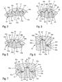
- Fig. 1
- eine erfindungsgemäße Axialkolbenmaschine im axialen Schnitt;
- Fig. 2
- den Teilschnitt II-II in Fig. 1 mit mehreren abgewandelten Ausgestaltungen;
- Fig. 3
- einen dem Teilschnitt entsprechenden Schnitt in weiter abgewandelter Ausgestaltung;
- Fig. 4
- eine erfindungsgemäße Axialkolbenmaschine im axialen Schnitt in weiter abgewandelter Ausgestaltung;
- Fig. 5
- den Teilschnitt V-V in Fig. 4;
- Fig. 6
- einen dem Teilschnitt V-V entsprechenden Schnitt in abgewandelten Ausgestaltungen und
- Fig. 7
- einen dem Teilschnitt V-V entsprechenden Schnitt in weiter abgewandelten Ausgestaltungen.
- Fig. 1
- an axial piston according to the invention in axial section;
- Fig. 2
- the partial section II-II in Figure 1 with a plurality of modified embodiments.
- Fig. 3
- a section corresponding to the section in a further modified embodiment;
- Fig. 4
- an axial piston according to the invention in axial section in a further modified embodiment;
- Fig. 5
- the partial section VV in Fig. 4;
- Fig. 6
- a section corresponding to the partial section VV in modified embodiments and
- Fig. 7
- a section corresponding to the partial section VV in further modified embodiments.
Die beispielhaft dargestellte Axialkolbenmaschine 1 weist ein geschlossenes Gehäuse 2 auf mit einem topfförmigen Gehäuseteil 3, dessen Gehäuseinnenraum 4 durch ein sogenanntes Anschlußteil 5 lösbar verschlossen ist, das im Sinne eines Deckels am freien Rand des Gehäuseteils 3 durch andeutungsweise dargestellte Schrauben 6 verschraubt ist. Im Gehäuse 2 ist eine Triebwelle 7 drehbar gelagert, die die Bodenwand 3a des topfförmigen Gehäuses 3 in einem Lagerloch 8 durchsetzt und durch Wälzlager 9, 11 mittelbar oder unmittelbar an der Bodenwand 3a des topfförmigen Gehäuses 3 und am Anschlußteil 5 frei drehbar gelagert ist. An der Innenseite des Anschlußteils 5 ist eine Steuerscheibe 13 mit etwa parallel zur Drehachse 7a der Triebwelle 7 einander gegenüberliegend verlaufenden Steuerkanälen 14, die jeweils mit einer Zuführungsleitung 15 und einer Abführungsleitung 16 im Anschlußteil 5 verbunden sind, angeordnet. An der Innenseite der Steuerscheibe 13 liegt eine Zylindertrommel 17 an, die mit einem Längsloch 18 auf der Triebwelle 7 sitzt und damit durch eine Vielzahnkupplung 19 drehfest verbunden ist, die beim vorliegenden Ausführungsbeispiel nur in einem der Steuerscheibe 13 abgewandten Endbereich der Zylindertrommel 17 und einem diesem radial benachbarten Längsbereich der Triebwelle 7 angeordnet ist.The axial piston machine 1 shown by way of example has a closed
In der Zylindertrommel 17 sind auf dem Umfang verteilt mehrere sich etwa achsparallel erstreckende Kolbenbohrungen 21 angeordnet, die an ihren den Steuerkanälen 14 zugewandten Enden durch verjüngte Zuführungs- und Abführungskanäle 22 mit den Steuerkanälen 14 verbunden sind und an der der Steuerscheibe 13 abgewandten Seite aus der Zylindertrommel 17 ausmünden. In den Kolbenbohrungen 21 sind Kolben 23 axial hin und her verschiebbar gelagert, die mit ihren der Steuerscheibe 13 zugewandten Enden Arbeitskammern 24 in den Kolbenbohrungen 21 begrenzen und mit ihren der Steuerscheibe 13 abgewandten Kopfenden aus der Zylindertrommel 17 herausragen und mittels Stützgelenken 25, insbesondere Kugelgelenken, in einer schrägverlaufenden Querebene an einer Schrägscheibe 26 axial abgestützt sind. Bei einer vorliegenden Axialkolbenmaschine 1 in Schrägscheibenbauweise ist die Schrägscheibe 26 durch eine sogenannte Schrägscheibe gebildet, die bei einer Axialkolbenmaschine 1 unveränderlichen Durchsatzvolumens starr und bei einer Axialkolbenmaschine 1 veränderlichen Durchsatzvolumens um eine sich rechtwinklig zur Drehachse 7a erstreckende Schwenkachse 27 schwenkbar gelagert ist und durch eine an sich bekannte und nicht dargestellte Verstellvorrichtung verstellbar und in der jeweils eingestellten Position feststellbar ist. Hierzu können hohlzylinderabschnittsförmige Lagerflächen 31a an der Schwenkscheibe und einem Schwenklager dienen. Die Schrägscheibe weist an ihrer der Zylindertrommel 17 zugewandten Seite eine Schrägfläche 26a auf, an der die Kolben 23 mittels Gleitschuhen 29 abgestützt sind, die durch die Stützgelenke 25 mit den Kopfenden der Kolben 23 allseitig schwenkbar verbunden sind.In the
Beim vorliegenden Ausführungsbeispiel ist die Schrägscheibe 26 an der Bodenwand 3a gelagert, wobei hierzu ein Lagerring 31 vorgesehen sein kann, der an der Bodenwand 3a abgestützt ist und ein Lagerloch aufweist, in dem das zugehörige Wälzlager 9 gelagert ist. In der Schrägscheibe 26 ist ein axiales Durchgangsloch angeordnet, durch das sich die Triebwelle 7 mit Bewegungsspiel hindurch erstreckt.In the present embodiment, the
Im Funktionsbetrieb der Axialkolbenmaschine 1 rotieren die Triebwelle 7 und die Zylindertrommel 17 gemeinsam um die Drehachse 7a, wobei die Kolben aufgrund der schrägen Ebene an der Schrägscheibe 26, hier an der Schrägfläche 26a, in den Kolbenbohrungen 21 hin und her verschoben werden. Dabei kann die Axialkolbenmaschine 1 im Pumpenbetrieb oder im Motorbetrieb arbeiten. Um ein Abheben der Gleitschuhe 29 von der Schrägfläche 26a zu verhindern, ist den Gleitschuhen 29 eine Rückzugvorrichtung 33 zugeordnet, die die Gleitschuhe 29 in Anlage an der Schrägfläche 26a hält und beim vorliegenden Ausführungsbeispiel durch eine Rückzugscheibe 33 gebildet ist, die mit Lochrändern 35 Flansche 29a der Gleitschuhe 29 in an sich bekannter Weise hintergreift. Die Rückzugscheibe 33 ist mit einer kugelzonenförmigen konkaven Lagerfläche 37 an einer entsprechend kugelzonenförmigen konvexen Lagerfläche 38 an einem Stützring 39 axial abgestützt, der mit einem Lagerloch 41 axial verschiebbar auf der Triebwelle 7 gelagert ist und in Richtung auf die Zylindertrommel 17 mit einer Kraft abgestützt ist, die größer ist, als die Abhebekräfte. Der Stützring 39 ist vorzugsweise durch eine zweite Vielzahnkupplung 19a drehfest mit der Triebwelle 7 verbunden, wobei die Zähne 43a gemeinsam für beide Vielzahnkupplungen vorgesehen und entsprechend lang sein können.In functional operation of the axial piston machine 1, the
Um eine gute Abdichtung zwischen der Zylindertrommel 17 und der Steuerscheibe 13 zu erreichen, ist es vorteilhaft, die Zylindertrommel 17 mit einer axialen elastischen Kraft gegen die Steuerscheibe 13 vorzuspannen. Beim Ausführungsbeispiel nach Fig. 1 werden für die Gleitschuhe 29 und die Zylindertrommel 17 Andruckkräfte durch eine gemeinsame axial wirksame Feder 42 erzeugt, die z. B. zwischen dem Stützring 39 und der Zylindertrommel 17 angeordnet sein kann und diese Teile auseinanderdrückt.In order to achieve a good seal between the
Wie insbesondere aus Fig. 2 zu entnehmen ist, besteht die Vielzahnkupplung 19 aus einer Mehrzahl von an der Mantelfläche der Triebwelle 7 bzw. an der Innenmantelfläche der Zylindertrommel 13 angeordneten und jeweils in Umfangsrichtung einander regelmäßig abwechselnd folgenden Zähnen 43a, 44a und Zahnlücken 43b, 44b deren Hauptform und Größe jeweils so ausgebildet ist, daß die Zähne die Zahnlücken im wesentlichen ausfüllen. Bei der Drehmitnahme im Funktionsbetrieb werden die Zähne jeweils in Umfangsrichtung belastet, wobei in Umfangsrichtung wirksame Druckkräfte übertragen werden, die eine bestimmte Flächenpressung an den die Zähne 43a, 44a begrenzenden Zahnflanken 43c, 44c erzeugen. Die sich zwischen den Flanken 43c, 44c erstreckenden Flächen sind mit Kopfflächen 43d, 44d und Zahnlückengrundflächen 43e, 44e bezeichnet.2, the multi-tooth clutch 19 consists of a plurality of
Aufgrund der soweit beschriebenen Formgebung bildet die Vielzahnkupplung 19 aufgrund der verhältnismäßig dichten Anlage eine Sperrwand bzw. Barriere, die eine Strömung des Fluids zwischen den zu beiden Seiten der Vielzahnkupplung 19 angeordneten Innenraumabschnitten 4a, 4b verhindert. Um eine Strömung und somit einen Fluidaustausch zwischen dem Innenraumabschnitten 4a, 4b zu ermöglichen, weist die Verzahnung vorzugsweise mittig in wenigstens einer Zahnkopffläche 43d, 44d und/oder in wenigstens einer Zahnlückengrundfläche 43e, 44e der Triebwelle 7 und/oder der Zylindertrommel 17 einen Durchführungskanal 45 auf, der somit die beiden Innenraumabschnitte 4a, 4b miteinander verbindet, so daß eine Strömung stattfinden kann. Hierdurch werden die Schmierung jeweils zugehöriger Flächen verbessert und Verschleiß, Abrieb und Kontaktkorrosion verhindert oder zumindest vermindert. Wenn ein Innenraumabschnitt 4a, 4b an einem Leckageabfluß angeschlossen ist, dient der Durchführungskanal auch dazu, den anderen Innenraumabschnitt 4b mit dem Leckageabfluß zu verbinden.Due to the shape described so far forms the multi-tooth clutch 19 due to the relatively dense system a barrier wall or barrier, which prevents flow of the fluid between the arranged on both sides of the multi-tooth clutch 19
Der wenigstens eine Durchführungskanal 45 hat wegen seiner Ausmündung zur zugehörigen Kopf- oder Grundfläche 43d, 44d, 43e, 44e eine Nut, die sich in einem Arbeitsschritt mit dem Zahnprofil herstellen läßt, z. B. durch ein Räum-, Stoß- oder Rollhammer-Werkzeug. Um die Querschnittsfläche des Durchgangskanals 45 zu vergrößern, ist es vorteilhaft, Durchführungskanäle 45 in beiden einander gegenüberliegenden Zahnkopfflächen 43d und/oder 44d und Zahnlückengrundflächen 43e und/oder 44e einander radial gegenüberliegend anzuordnen. Wenn mehrere Durchführungskanäle 45 einander gegenüberliegend oder allein auf dem Umfang verteilt angeordnet sind, läßt sich der wirksame Strömungsquerschnitt weiter vergrößern.The at least one
Die Querschnittsform des wenigstens einen Durchführungskanals 45 kann gerundet (Fig. 2 und 5) oder kreisbogenabschnittförmig gekrümmt (Fig. 7) oder eckig (Fig. 3 und 6) sein, z. B. viereckig oder dreieckig geformt sein. Dabei können die Durchführungskanäle 45 in den Zahnkopfflächen 43d, 44d und/oder in den Zahnlückengrundflächen 43e, 44e der Triebwelle 7 und/oder der Zylindertrommel 17 einander in Umfangsrichtung direkt folgend oder bei Auslassung einer oder mehrerer Zannkopfflächen 43d, 44d und/oder Zahnlückengrundflächen 43e, 44e angeordnet sein. Die vorgenannten und noch zu beschreibenden Ausführungsbeispiele können wahlweise in Kombination oder jeweils für sich angewandt werden.The cross-sectional shape of the at least one
Bei den Ausführungsbeispielen nach Fig. 4 bis 7, bei denen gleiche oder vergleichbare Teile mit gleichen Bezugszeichen versehen sind, ist die Feder 42 auf der der Steuerscheibe 13 zugewandten Seite der Vielzahnkupplung 19 in einem zwischen der Zylindertrommel 17 und der Triebwelle 7 angeordneten Ringraum angeordnet und vorzugsweise durch eine Wendelfeder gebildet, die mit ihrem der Steuerscheibe 13 zugewandten Ende gegen eine innere Schulterfläche 47 an der Zylindertrommel 17 drückt und diese gegen die Steuerscheibe 13 vorspannt. Das der Steuerscheibe 13 abgewandte Ende der Feder 42 spannt mit mehreren einander gegenüberliegend angeordneten axialen Druckstiften 48, die sich durch jeweils einen Durchführungskanal 45 bis zum Stützring 39 erstrecken, die Rückzugvorrichtung 33 vor. Zwischen den Druckstiften 48 und der Feder 42 kann ein Druckring 49 angeordnet sein. Die Länge der Druckstifte 48 ist größer bemessen, als die axiale Länge der Vielzahnkupplung 19, so daß sie in den Ringraum 46 hineinragen. Es sind mehrere, auf dem Umfang verteilt angeordnete Druckstifte 48 und diese aufnehmende Durchführungskanäle 45 vorhanden, um die axiale Andruckkraft auf dem Umfang zu verteilen.In the embodiments of FIGS. 4 to 7, in which the same or comparable parts are provided with the same reference numerals, the
Bei diesen Ausführungsbeispielen bilden die Durchführungskanäle 45 axiale Führungen für die Druckstifte 48. Wenn die Querschnittsform und -größe der Durchführungskanäle 45 mit einem geringen Bewegungsspiel an die Querschnittsform und -größe der Druckstifte 48 angepaßt ist, erfüllen die Durchführungskanäle 45 ausschließlich eine Führungsfunktion für die Druckstifte 48. In einem solchen Fall kann durch einen anderen Strömungsdurchgang dafür gesorgt sein, daß das Fluid von dem einen Gehäuseinnenraumabschnitt 4a zu dem anderen 4b, hier in den Ringraum 46 und zum Wälzlager 11, gelangt, um diesen Bereich zu schmieren und ggf. auch zu kühlen und/oder zu spülen. Eine angepaßte Querschnittsform ergibt sich z. B. dann, wenn zwei z. B. halbrunde Durchführungskanäle 45 einander gegenüberliegend angeordnet sind, in die ein gemeinsamer runder oder viereckiger Druckstift 48 mit geringem Bewegungsspiel einfaßt, wie es Fig. 7 rechts zeigt.In these embodiments, the
Es ist vorteilhaft, die Durchführungskanäle 45 so auszugestalten, daß sie sowohl eine Führungsfunktion für die Druckstifte 48 bilden als auch wenigstens einen Durchgang für das Fluid bilden. Dies kann dadurch erreicht werden, daß die Anzahl der Durchführungskanäle 45 größer ist als die Anzahl der Druckstifte 48 und somit wenigstens ein Durchführungskanal 45 als freier Durchgang dienen kann. Dies kann aber auch dadurch erreicht werden, daß die Querschnittsform der Durchführungskanäle 45 und die der Druckstifte 48 unterschiedlich ist. Hierzu bietet sich eine eckige Form für die Durchführungskanäle 45 und eine runde Form für die Druckstifte 48 an. Auch in diesem Fall können einander gegenüberliegende, z. B. im Querschnitt eckige Durchführungskanäle 45 einen gemeinsamen Druckstift 48 unterschiedlicher, z. B. runder Querschnittsform, aufnehmen, wie es Fig. 7 links zeigt. Dabei können die Durchführungskanäle 45 eine Führungsfunktion auf die Druckstifte 48 ausüben, indem Letztere linienförmig geführt sind und freie Durchführungskanalquerschnitte 45a verbleiben, durch die ein Fluidstrom stattfinden kann.It is advantageous to design the
Allen erfindungsgemäßen Ausführungsbeispielen ist gemeinsam, daß eine Schwächung der Zahnflanken 43c und 44c vermieden wird. Da keine Zähne 43a, 44a entfallen, wird trotz der Durchführungskanäle 45 eine effektive Verbindung zwischen Triebwelle 7 und Zylindertrommel 17 geschaffen.All embodiments of the invention have in common that a weakening of the tooth flanks 43c and 44c is avoided. Since no
Claims (12)
- Axial piston engine (1) having a housing (2), the housing interior (4) of which contains a cylinder drum (17) and a swash plate (26) disposed axially adjacent to the latter,
wherein disposed in the cylinder drum (17) and extending substantially parallel to the centre line of the latter is a plurality of piston bores (21), in which pistons (23) are displaceably guided, of which the piston ends facing the swash plate (26) are supported against the swash plate (26),
wherein a driving shaft (7) is rotatably mounted in the housing (2) and is connected non-rotatably to a engine part by a regular alternating arrangement of mutually meshing teeth (43a, 44a) and tooth spaces (43b, 44b) in peripheral direction, and
wherein disposed in the region of the multitooth coupling (19) is at least one through-channel (45), which extends substantially parallel to the axis of rotation of the driving shaft (7) and from the one side of the multitooth coupling (19) to the other,
characterized in
that the through-channel (45) is disposed in a tooth tip surface (43b, 44e) and/or in a tooth space bottom surface (44e, 43b) lying opposite the latter, and
that the through-channel (45) has a groove and discharges in the direction of the associated tooth tip surface (43b, 44e) and/or tooth space bottom surface (44e, 43b). - Axial piston engine according to claim 1,
characterized in
that the cross-sectional shape of the through-channel (45) is rounded or U-shaped. - Axial piston engine according to claim 1,
characterized in
that the cross-sectional shape of the through-channel (45) is polygonal, e.g. triangular or square. - Axial piston engine according to one of the preceding claims,
characterized in
that the through-channel (45) extends in both mutually opposing tooth tip surfaces (43d) and tooth space bottom surfaces (44d). - Axial piston engine according to one of the preceding claims,
characterized in
that a plurality of through-channels (45) distributed over the periphery are disposed in each case in a tooth tip surface (43d, 44d) and/or tooth space bottom surface (43e, 44e). - Axial piston engine according to claim 5,
characterized in
that a thrust pin (48) is disposed as part of a mechanical penetration and/or connecting apparatus in each of a plurality of through-channels (45) arranged so as to be distributed over the periphery and is preferably longer than the multitooth coupling (19). - Axial piston engine according to claim 6,
characterized in
that the thrust pins (28) are biased by the action of a spring (42) towards a return apparatus (39) for sliding pads (29). - Axial piston engine according to claim 6 or 7,
characterized in
that the shape and size of the cross section of the through-channels (45) are adapted to the shape and size of the cross section of the thrust pins (48). - Axial piston engine according to one of claims 6 to 8,
characterized in
that the through-channels (45) and the thrust pins (48) disposed therein have different cross-sectional shapes. - Axial piston engine according to one of claims 6 to 9,
characterized in
that the thrust pins (48) have a round cross-sectional shape. - Axial piston engine according to one of claims 6 to 10,
characterized in
that a thrust ring (49) is disposed between the ends of the thrust pins (48) remote from the return apparatus (33) and a pressure spring (42) formed in particular by a cylindrical helical spring. - Axial piston engine according to claim 11,
characterized in
that the thrust ring (49) and the thrust pins (48) are of an integral construction.
Applications Claiming Priority (3)
| Application Number | Priority Date | Filing Date | Title |
|---|---|---|---|
| DE10028336A DE10028336C1 (en) | 2000-06-08 | 2000-06-08 | Engine with axial piston has through guide channel between at least one tooth crown surface and tooth space bottom opposite it |
| DE10028336 | 2000-06-08 | ||
| PCT/EP2001/002255 WO2001094751A1 (en) | 2000-06-08 | 2001-02-28 | Axial piston engine |
Publications (2)
| Publication Number | Publication Date |
|---|---|
| EP1287232A1 EP1287232A1 (en) | 2003-03-05 |
| EP1287232B1 true EP1287232B1 (en) | 2006-12-27 |
Family
ID=26006018
Family Applications (1)
| Application Number | Title | Priority Date | Filing Date |
|---|---|---|---|
| EP01915304A Expired - Lifetime EP1287232B1 (en) | 2000-06-08 | 2001-02-28 | Axial piston engine |
Country Status (4)
| Country | Link |
|---|---|
| US (1) | US6796774B2 (en) |
| EP (1) | EP1287232B1 (en) |
| DE (1) | DE10028336C1 (en) |
| WO (1) | WO2001094751A1 (en) |
Families Citing this family (3)
| Publication number | Priority date | Publication date | Assignee | Title |
|---|---|---|---|---|
| JP4111901B2 (en) * | 2003-09-26 | 2008-07-02 | 株式会社日本自動車部品総合研究所 | Fluid machinery |
| US9752570B2 (en) | 2014-02-13 | 2017-09-05 | S-RAM Dynamics | Variable displacement compressor and expander |
| EP3020966B1 (en) * | 2014-11-11 | 2020-01-22 | Danfoss A/S | Axial piston machine |
Family Cites Families (8)
| Publication number | Priority date | Publication date | Assignee | Title |
|---|---|---|---|---|
| US2776627A (en) * | 1952-07-10 | 1957-01-08 | Vickers Inc | Power transmission |
| DE1405856A1 (en) * | 1960-05-27 | 1969-01-02 | Daimler Benz Ag | Non-rotatable connection between torque-transmitting parts of motor vehicle transmissions, e.g. Connection of gears with their shafts |
| US3139038A (en) * | 1961-07-17 | 1964-06-30 | Applied Power Ind Inc | Engine |
| US3675539A (en) * | 1970-08-07 | 1972-07-11 | Parker Hannifin Corp | Hydraulic motor |
| US3698287A (en) * | 1970-12-09 | 1972-10-17 | Cessna Aircraft Co | Axial piston device |
| DE3222210A1 (en) * | 1982-06-12 | 1983-12-15 | Linde Ag, 6200 Wiesbaden | Swashplate-type axial-piston engine |
| DE4206087C2 (en) * | 1992-02-27 | 1994-01-27 | Linde Ag | Hydromechanical wheel drive |
| US5784949A (en) * | 1997-06-25 | 1998-07-28 | Sauer Inc. | Retaining system for slipper holddown pins |
-
2000
- 2000-06-08 DE DE10028336A patent/DE10028336C1/en not_active Expired - Fee Related
-
2001
- 2001-02-28 WO PCT/EP2001/002255 patent/WO2001094751A1/en active IP Right Grant
- 2001-02-28 US US10/220,325 patent/US6796774B2/en not_active Expired - Fee Related
- 2001-02-28 EP EP01915304A patent/EP1287232B1/en not_active Expired - Lifetime
Also Published As
| Publication number | Publication date |
|---|---|
| WO2001094751A1 (en) | 2001-12-13 |
| US6796774B2 (en) | 2004-09-28 |
| US20030010195A1 (en) | 2003-01-16 |
| DE10028336C1 (en) | 2002-04-04 |
| EP1287232A1 (en) | 2003-03-05 |
Similar Documents
| Publication | Publication Date | Title |
|---|---|---|
| EP1078165B1 (en) | Spiral compressor | |
| EP0162238B1 (en) | Axial piston machine, especially a pump of the inclined plate type | |
| EP0102915B1 (en) | Radial-piston hydraulic engine | |
| DE3014520A1 (en) | TURNING PISTON | |
| DE3213855A1 (en) | PISTON PISTON ENGINE WITH SWASH DISC MECHANISM | |
| DE2645992C2 (en) | ||
| DE2921902A1 (en) | MULTICYLINDRICAL, HYDRAULIC PUMP AND MOTOR WITH PUMP BOOTS AND WITH A CHANGEABLE VOLUME THROUGH ITS INCLINATION | |
| DE882932C (en) | Spaciously working reciprocating gear | |
| DE3342131C2 (en) | ||
| DE2403173B2 (en) | Double mechanical seal | |
| EP1287232B1 (en) | Axial piston engine | |
| DE2631376B1 (en) | Cross-head journal bearings for piston engines, especially for diesel internal combustion engines | |
| EP0341390B1 (en) | Piston device for a piston unit | |
| DE60310370T2 (en) | RADIAL ROTARY MACHINE | |
| WO2003025347A1 (en) | Hydrostatic machine with compensated sleeves | |
| WO2002034475A1 (en) | Hand-held machine tool comprising a sealing ring disposed in the tool holder | |
| DE4232191C1 (en) | Device to adjust eccentricity of eccentric radial bearing - has hydraulic double-piston driving unit and releaseable locking device to move eccentric ring | |
| WO2005064158A1 (en) | Piston machine, shaft and anti-friction bearing for a piston machine | |
| DE60110314T2 (en) | axial piston pump | |
| DE4237463C2 (en) | Differential gear | |
| DE10017780B4 (en) | piston engine | |
| DE1176954B (en) | Infinitely variable hydrostatic power transmission | |
| DE19747915C2 (en) | Axial piston machine | |
| DE2652177C2 (en) | Reciprocating assembly | |
| EP1041279A2 (en) | Valve plate for axial piston machine |
Legal Events
| Date | Code | Title | Description |
|---|---|---|---|
| PUAI | Public reference made under article 153(3) epc to a published international application that has entered the european phase |
Free format text: ORIGINAL CODE: 0009012 |
|
| 17P | Request for examination filed |
Effective date: 20020809 |
|
| AK | Designated contracting states |
Kind code of ref document: A1 Designated state(s): AT BE CH CY DE DK ES FI FR GB GR IE IT LI LU MC NL PT SE TR |
|
| RBV | Designated contracting states (corrected) |
Designated state(s): AT BE CH CY DE FR GB IT LI SE |
|
| GRAP | Despatch of communication of intention to grant a patent |
Free format text: ORIGINAL CODE: EPIDOSNIGR1 |
|
| RBV | Designated contracting states (corrected) |
Designated state(s): DE FR GB IT SE |
|
| GRAS | Grant fee paid |
Free format text: ORIGINAL CODE: EPIDOSNIGR3 |
|
| GRAA | (expected) grant |
Free format text: ORIGINAL CODE: 0009210 |
|
| AK | Designated contracting states |
Kind code of ref document: B1 Designated state(s): DE FR GB IT SE |
|
| REG | Reference to a national code |
Ref country code: GB Ref legal event code: FG4D Free format text: NOT ENGLISH |
|
| GBT | Gb: translation of ep patent filed (gb section 77(6)(a)/1977) |
Effective date: 20061228 |
|
| REF | Corresponds to: |
Ref document number: 50111740 Country of ref document: DE Date of ref document: 20070208 Kind code of ref document: P |
|
| REG | Reference to a national code |
Ref country code: SE Ref legal event code: TRGR |
|
| ET | Fr: translation filed | ||
| PLBE | No opposition filed within time limit |
Free format text: ORIGINAL CODE: 0009261 |
|
| STAA | Information on the status of an ep patent application or granted ep patent |
Free format text: STATUS: NO OPPOSITION FILED WITHIN TIME LIMIT |
|
| 26N | No opposition filed |
Effective date: 20070928 |
|
| PGFP | Annual fee paid to national office [announced via postgrant information from national office to epo] |
Ref country code: GB Payment date: 20080220 Year of fee payment: 8 Ref country code: IT Payment date: 20080223 Year of fee payment: 8 Ref country code: SE Payment date: 20080214 Year of fee payment: 8 |
|
| PGFP | Annual fee paid to national office [announced via postgrant information from national office to epo] |
Ref country code: FR Payment date: 20080214 Year of fee payment: 8 |
|
| GBPC | Gb: european patent ceased through non-payment of renewal fee |
Effective date: 20090228 |
|
| EUG | Se: european patent has lapsed | ||
| REG | Reference to a national code |
Ref country code: FR Ref legal event code: ST Effective date: 20091030 |
|
| PG25 | Lapsed in a contracting state [announced via postgrant information from national office to epo] |
Ref country code: FR Free format text: LAPSE BECAUSE OF NON-PAYMENT OF DUE FEES Effective date: 20090302 Ref country code: GB Free format text: LAPSE BECAUSE OF NON-PAYMENT OF DUE FEES Effective date: 20090228 |
|
| PG25 | Lapsed in a contracting state [announced via postgrant information from national office to epo] |
Ref country code: IT Free format text: LAPSE BECAUSE OF NON-PAYMENT OF DUE FEES Effective date: 20090228 |
|
| PG25 | Lapsed in a contracting state [announced via postgrant information from national office to epo] |
Ref country code: SE Free format text: LAPSE BECAUSE OF NON-PAYMENT OF DUE FEES Effective date: 20090301 |
|
| PGFP | Annual fee paid to national office [announced via postgrant information from national office to epo] |
Ref country code: DE Payment date: 20120423 Year of fee payment: 12 |
|
| REG | Reference to a national code |
Ref country code: DE Ref legal event code: R119 Ref document number: 50111740 Country of ref document: DE Effective date: 20130903 |
|
| PG25 | Lapsed in a contracting state [announced via postgrant information from national office to epo] |
Ref country code: DE Free format text: LAPSE BECAUSE OF NON-PAYMENT OF DUE FEES Effective date: 20130903 |