EP1286445A2 - Control system and method for a vehicle generator - Google Patents
Control system and method for a vehicle generator Download PDFInfo
- Publication number
- EP1286445A2 EP1286445A2 EP02254862A EP02254862A EP1286445A2 EP 1286445 A2 EP1286445 A2 EP 1286445A2 EP 02254862 A EP02254862 A EP 02254862A EP 02254862 A EP02254862 A EP 02254862A EP 1286445 A2 EP1286445 A2 EP 1286445A2
- Authority
- EP
- European Patent Office
- Prior art keywords
- voltage
- generator
- command value
- system equipment
- generation command
- Prior art date
- Legal status (The legal status is an assumption and is not a legal conclusion. Google has not performed a legal analysis and makes no representation as to the accuracy of the status listed.)
- Granted
Links
Images

Classifications
-
- H—ELECTRICITY
- H02—GENERATION; CONVERSION OR DISTRIBUTION OF ELECTRIC POWER
- H02J—ELECTRIC POWER NETWORKS; CIRCUIT ARRANGEMENTS OR SYSTEMS FOR SUPPLYING OR DISTRIBUTING ELECTRIC POWER; SYSTEMS FOR STORING ELECTRIC ENERGY
- H02J7/00—Circuit arrangements for charging or discharging batteries or for supplying loads from batteries
- H02J7/14—Circuit arrangements for charging or discharging batteries or for supplying loads from batteries for charging batteries from dynamo-electric generators driven at varying speed, e.g. on vehicle
- H02J7/1446—Circuit arrangements for charging or discharging batteries or for supplying loads from batteries for charging batteries from dynamo-electric generators driven at varying speed, e.g. on vehicle in response to parameters of a vehicle
-
- H—ELECTRICITY
- H02—GENERATION; CONVERSION OR DISTRIBUTION OF ELECTRIC POWER
- H02J—ELECTRIC POWER NETWORKS; CIRCUIT ARRANGEMENTS OR SYSTEMS FOR SUPPLYING OR DISTRIBUTING ELECTRIC POWER; SYSTEMS FOR STORING ELECTRIC ENERGY
- H02J7/00—Circuit arrangements for charging or discharging batteries or for supplying loads from batteries
- H02J7/14—Circuit arrangements for charging or discharging batteries or for supplying loads from batteries for charging batteries from dynamo-electric generators driven at varying speed, e.g. on vehicle
- H02J7/16—Regulation of the charging current or voltage by variation of field
- H02J7/24—Regulation of the charging current or voltage by variation of field using discharge tubes or semiconductor devices
- H02J7/2434—Regulation of the charging current or voltage by variation of field using discharge tubes or semiconductor devices with pulse modulation
-
- Y—GENERAL TAGGING OF NEW TECHNOLOGICAL DEVELOPMENTS; GENERAL TAGGING OF CROSS-SECTIONAL TECHNOLOGIES SPANNING OVER SEVERAL SECTIONS OF THE IPC; TECHNICAL SUBJECTS COVERED BY FORMER USPC CROSS-REFERENCE ART COLLECTIONS [XRACs] AND DIGESTS
- Y02—TECHNOLOGIES OR APPLICATIONS FOR MITIGATION OR ADAPTATION AGAINST CLIMATE CHANGE
- Y02T—CLIMATE CHANGE MITIGATION TECHNOLOGIES RELATED TO TRANSPORTATION
- Y02T10/00—Road transport of goods or passengers
- Y02T10/80—Technologies aiming to reduce greenhouse gasses emissions common to all road transportation technologies
- Y02T10/92—Energy efficient charging or discharging systems for batteries, ultracapacitors, supercapacitors or double-layer capacitors specially adapted for vehicles
Definitions
- the present invention relates to a control system and method for a vehicle generator, particularly of the kind capable of attaining improved vehicle acceleration ability, improved fuel consumption, and suitable power supply in accordance with a loaded condition of the generator.
- a vehicle generator is connected to a rotational shaft of an engine and is therefore caused to vary in rotational speed over a wide range. For this reason, the vehicle generator is provided with a regulator (control system) for regulating generated voltage within a suitable range.
- the regulator of this kind controls the generated voltage by intermittently operating the generator through ON/OFF control of the field current of the generator. When the load on the generator becomes larger, the generation time is controlled so as to become longer for maintaining the generated voltage constant.
- the conditions under which the vehicle electrical equipments are used vary largely depending upon whether it is used in the daytime or night, or the season it is used. If the power generation time is shortened for the purpose of improving the acceleration ability and fuel consumption, there will be caused a problem of overdischarge of the battery and flickering of lamps when the working power is large. On the contrary, if the power generation time is made longer upon deceleration of the vehicle, there will be caused a problem of overcharge of the battery and burning out of lamps.
- a regulator for adequately controlling the power generation time during which power is generated, in accordance with the load on the generator as disclosed in Japanese Patent Provisional Publication No. 4-63639.
- the regulator controls the power generated by the generator in relation to acceleration and deceleration of the vehicle and vehicle speed thereby reducing the power generation torque allotted to the engine and improving the acceleration ability and fuel consumption of the vehicle.
- the above described regulator is constructed so as to execute a control for reducing the generated power for the purpose of improving the acceleration ability and fuel consumption of the vehicle, while at the same time inhibiting the above described control when certain electrical equipments are turned on or when the value of current detected by a current detector becomes equal to or higher than a predetermined value for the purpose of preventing a variation of performance of electrical equipments due to a variation of generated voltage, for example, flickering of lamps.
- a control system for a vehicle generator comprising a first detector for detecting a running condition of a vehicle and producing a signal representative thereof, a second detector for detecting whether vehicle electrical equipments are ON or OFF, and a controller responsive to the signals from the first detector and the second detector for controlling a field current of the generator thereby controlling an output voltage of the generator, wherein the controller is programmed to send to the generator, if the vehicle electrical equipments are OFF and the vehicle is in a running condition other than a decelerating condition, a generation command value that is a first target voltage lower than a normal generation voltage, send to the generator, if the electrical equipments are OFF and the vehicle is in the decelerating condition, a generation command value that is a second target voltage higher than the normal generation voltage, and send to the generator, if one of the electrical equipments is ON, a generation command value that is a third target voltage lower than the normal generation voltage and higher than the first target voltage.
- a control method for a vehicle generator comprising detecting a running condition of a vehicle and producing a first signal representative thereof, detecting whether vehicle electrical equipments are ON or OFF and producing a second signal representative thereof, and controlling, in response to the first and second signals, a field current of the generator thereby controlling an output voltage of the generator, wherein the controlling of the field current of the generator including sending to the generator, if the vehicle electrical equipments are OFF and the vehicle is in a running condition other than a decelerating condition, a generation command value that is a first target voltage lower than a normal generation voltage, sending to the generator, if the electrical equipments are OFF and the vehicle is in the decelerating condition, a generation command value that is a second target voltage higher than the normal generation voltage, and sending to the generator, if predetermined one of the electrical equipments is ON, a generation command value that is a third target voltage higher than the first target voltage.
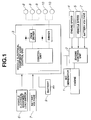
- generator 1 is connected to an output shaft of an engine (no numeral) so as to be driven by the engine.
- Engine control unit 2 executes various controls of the engine.
- engine control unit 2 is supplied with various information such as engine speed from engine speed sensor 4, vehicle speed from vehicle speed sensor 5, and battery voltage from voltmeter 7 for battery 9.
- Engine control unit 2 determines a vehicle running condition, i.e., whether the vehicle is in an idling condition, accelerating condition, constant speed running condition, or decelerating condition, based on the information supplied thereto from engine speed sensor 4, vehicle speed sensor 5, voltmeter 7, etc.
- Engine control unit 2 thus cooperates with engine speed sensor 4, vehicle speed sensor 5, voltmeter 7, etc. to constitute a first detector that detects a running condition of the vehicle and produces a signal representative thereof.
- vehicle electrical equipment load control unit 3 determines the operating conditions of lamp system equipments 8, i.e., whether lamp system equipments 8 are in operation (i.e., ON) or out of operation (i.e., OFF) and the operating conditions of actuator system equipments 10, i.e., whether actuator system equipments 10 are in operation (i.e., ON) or out of operation (i.e., OFF).
- Vehicle electrical equipment load control unit 3 cooperates with vehicle electrical equipment load switches 6 and battery voltmeter 7 to constitute a second detector that detects the operating conditions of lamp system equipments 8 (i.e., whether lamp system equipments 8 are ON or OFF) and the operating conditions of actuator system equipments 10 (i.e., whether actuator system equipments 10 are ON or OFF) and produces signals representative thereof.
- engine control unit 2 Based on the information (i.e., the signal from the second detector) and in addition information on the vehicle running condition (i.e., the signal from the first detector), a process that will be described hereinafter is executed to control field current by controlling a generation command value given to generator 1.
- This section of engine control unit 2 corresponds to a controller responsive to the signal from the first detector and the second detector for controlling field current of generator 1 thereby controlling an output voltage of generator 1.
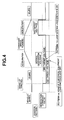
- FIG. 4 is a time chart for illustrating a control that is executed when it is determined that any of vehicle electrical equipment load switches 6 is OFF as a result of the detection of the operating conditions of vehicle electrical equipment load switches 6 by vehicle electrical equipment load control unit 3.
- a generation command value inputted to generator 1 is set at a second target voltage higher than a normal generation voltage, irrespective of whether vehicle electrical equipments 8 and 10 are ON or OFF. It is desirable for the generation command value to be set higher in the above-described manner in case the vehicle is in a decelerating condition since the torque load of generator 1 becomes larger to contribute to engine braking and power can be supplied to vehicle electrical equipments 8 and 10 efficiently.
- the generation command value of generator 1 is set at a first target voltage lower than the normal generation voltage.
- the torque load of generator 1 becomes smaller and therefore the torque load on the engine becomes smaller, thus making it possible to improve the acceleration ability and fuel consumption of the vehicle.
- the first target voltage is lower than the normal generation voltage, there is no influence on the vehicle electrical equipments since the OFF condition of vehicle electrical equipment load switches 6 is detected by vehicle electrical equipment load control unit 3.
- the generation command value when the vehicle is in one of the idling condition, accelerating condition and constant speed running condition is set at, in place of the first target voltage, a third target voltage that is higher than the first target voltage and lower than the normal generation voltage.
- the generation command value is unchanged and held at the second target voltage. This is because the second target voltage makes it assured to obtain a voltage necessary for the lamp system load sufficiently and contributes to the engine braking.
- the normal generation voltage is a voltage most suited to generator 1, and the target voltages and the normal generation voltage have such a relation that the first target voltage ⁇ the third target voltage ⁇ the normal generation voltage ⁇ the second target voltage.
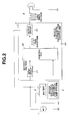
- a PWM control with the duty ratio of 100% is performed. If the inputted battery voltage is higher the reference voltage of lamp system equipments 8, a PWM control with a smaller duty ratio is performed. Namely, it is desirable that when the battery voltage is higher than the reference voltage of lamp system equipments 8, the supply voltage to lamp system equipments 8 is reduced to the reference voltage by the PWM control.
- lamp system equipments 8 can be uniform in the intensity of illumination and can be free from a problem of flickering when the vehicle is in the decelerating condition, i.e., the generation command value is set high.
- input circuit 31 constitutes a battery voltage detector for detecting charged voltage of battery 9
- control CPU 32 and output circuit 33 constitute a lamp system equipment controller for PWM controlling a voltage applied to lamp system equipment 8.
- the control pattern shown in FIG. 4 is a basic control of the present invention. Then, other applications of the control will be described.
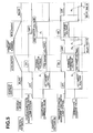
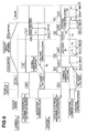
- FIG. 5 is a time chart of a control that is executed when lamp system load switch 6 is turned ON or OFF in the middle of the basic control of FIG. 4.
- the generation command value is maintained at the second target voltage even if lamp system load switch 6 is turned ON.
- the second target voltage makes it assured for the lamp system vehicle load to be supplied with necessary voltage and can contribute to engine braking.
- FIG. 6 is a time chart of a control that is executed when actuator system load switch 6 is turned ON or OFF in the middle of the basic control.
- actuator system load switch 6 is turned ON when the vehicle is in the decelerating condition, the generation command value is changed from the second target voltage so far toward the normal generation voltage linearly at a voltage changing speed - ⁇ (V/sec) (refer to range R2 in FIG. 6). This makes it assured to obtain the voltage applied to the actuator system load and prevents bad influence on the acceleration ability and fuel consumption since the generated voltage changes linearly.
- actuator system load switch 6 is turned OFF when the generation command value is the normal generation voltage
- the generation command value is changed from the normal generation voltage so far to the voltage for the basic control shown in FIG. 4 after a lapse of the delay time Dt.
- the delay time Dt is changed from the normal generation voltage so far to the second target voltage after a lapse of the delay time Dt (refer to P3 in FIG. 6).
- actuator system load switch 6 is turned OFF in the middle of linear changing of the generation command value
- the control is returned to the basic control after a lapse of a predetermined delay time Dt after the generation command value reached the normal generation voltage.
- a predetermined delay time Dt for example, as shown in the lower part of FIG. 6, if actuator system load switch 6 is turned ON when the vehicle is in the accelerating condition, thus causing the generation command value to be changed from the first target voltage toward the normal generation voltage linearly at a voltage changing speed + ⁇ , and then actuator system load switch 6 is turned OFF in the middle of linear changing of the generation command value, the generation command value is returned to the normal generation voltage after a lapse of the delay time Dt after the generation command value reached the normal generation voltage (refer to P4 in FIG. 6).
- actuator system load switch 6 is turned ON when the vehicle is in the decelerating condition, thus causing the generation command value to be changed from the second target voltage toward the normal generation voltage linearly at a voltage changing speed - ⁇ , and then actuator system load switch 6 is turned OFF in the middle of linear changing of the generation command value, the generation command value is returned to the first target voltage after a lapse of the delay time Dt after the generation command value reached the normal generation voltage (refer to P5 in FIG. 6).
- the generation command value is the normal generation voltage and actuator system load switch 6 is turned ON again during a wait for a lapse of delay time Dt, the normal generation voltage is maintained.
- the delay time Dt is measured again from the point of time when actuator system load switch 6 is turned OFF and the control is returned to the basic control after a lapse of the delay time Dt.
- actuator system load switch 6 is turned ON and then OFF when the vehicle is in the accelerating condition and is turned ON again during a wait for a first lapse of the delay time Dt as shown by the dotted line in FIG. 6, the generation command value that is the normal generation voltage is held as it is (refer to R2 in FIG. 6).
- the generation command value is changed to the first target voltage (refer to point P6 in FIG. 6).
- actuator system load switch 6 is turned ON and then OFF when the vehicle is in the decelerating condition and is turned ON again during a wait for a first lapse of the delay time Dt as indicated by the dotted line, the generation command value is held at the normal generation voltage as it is (refer to range R3 in FIG. 6). After a lapse of the delay time Dt after actuator system load switch 6 was turned OFF, the generation command value is changed to the first target generation voltage (refer to point P7 in FIG. 6).
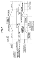
- FIG. 7 is a time chart of a control that is executed when both of lamp system load switch 6 and actuator system load switch 6 are turned ON or OFF during the basic control of FIG. 4.
- actuator system load switch 6 when either of lamp system load switch 6 and actuator system load switch 6 are ON, the control of actuator system load switch 6 is given priority and executed according to control patterns 3a and 3b shown in FIG. 6. If actuator system load switch 6 is turned ON in the middle of the basic control, the generation command value is changed from the command value for the basic control so far toward the normal generation voltage linearly at a voltage changing speed ⁇ ⁇ .
- the generation command value is changed from the first target voltage so far toward the normal generation voltage linearly at a voltage changing speed + ⁇ (refer to range R1 in FIG. 6).
- ON/OFF of lamp system load switch 6 does not cause any influence on the control. This makes it assured to obtain the voltage applied to the actuator system load and prevents bad influence on the acceleration ability and fuel consumption since the generated voltage changes linearly. Further, even if lamp system load switch 6 is turned ON or OFF in the middle of the control, the voltage applied to the lamp system load can be obtained assuredly.
- the generation command value is changed from the second target voltage so far toward the normal generation voltage linearly at a voltage changing speed - ⁇ (refer to range R2 in FIG. 7).
- ON/OFF of the lamp system load switch does not cause any influence on the control. This makes it assured to obtain the voltage applied to the actuator system load and prevents bad influence on the acceleration ability and fuel consumption since the generated voltage changes linearly. Further, even if the lamp system load switch is turned ON or OFF in the middle of the control, the voltage applied to the lamp system load can be obtained assuredly.
- actuator system load switch 6 is turned OFF and lamp system load switch 6 is turned ON after a lapse of the delay time Dt after the generation command value reached the normal generation voltage, the control is executed according to control patterns 2a and 2b shown in FIG. 5. Further, if, under this condition, lamp system load switch 6 is turned OFF, the control is executed according to the basic control pattern shown in FIG. 4.
Landscapes
- Engineering & Computer Science (AREA)
- Power Engineering (AREA)
- Control Of Eletrric Generators (AREA)
- Lighting Device Outwards From Vehicle And Optical Signal (AREA)
- Control Of Charge By Means Of Generators (AREA)
Abstract
Description
Claims (24)
- A control system for a vehicle generator (1) comprising:wherein the controller (2) is programmed to:a first detector (2, 4, 5, 7) for detecting a running condition of a vehicle and producing a signal representative thereof;a second detector (3, 6, 7) for detecting whether vehicle electrical equipments (8, 10) are ON or OFF and producing a signal representative thereof; anda controller (2) responsive to the signals from the first detector and the second detector for controlling a field current of the generator (1) thereby controlling an output voltage of the generator;send to the generator, if the vehicle electrical equipments (8, 10) are OFF and the vehicle is in a running condition other than a decelerating condition, a generation command value that is a first target voltage lower than a normal generation voltage;send to the generator, if the vehicle electrical equipments (8, 10) are OFF and the vehicle is in the decelerating condition, a generation command value that is a second target voltage higher than the normal generation voltage; andsend to the generator, if one of the vehicle electrical equipments (8, 10) is ON, a generation command value that is a third target voltage lower than the normal generation voltage and higher than the first target voltage.
- A control system according to claim 1, wherein the second detector (3, 6, 7) comprises a detecting section for detecting whether a lamp system equipment (8) of the vehicle electrical equipments (8, 10) is ON or OFF, and the controller (2) is programmed to send to the generator (1), if the lamp system equipment (8) is ON and the vehicle is in a running condition other than the decelerating condition, a generation command value that is the third target voltage.
- A control system according to claim 2, wherein the controller (2) is programmed to send to the generator (1), if the lamp system equipment (8) is ON and the vehicle is in the decelerating condition, a generation command value that is the second target voltage.
- A control system according to claim 2 or 3, wherein the controller is programmed to send to the generator (1), if the lamp system equipment (8) is turned ON in the middle of a control of a generation command value, a generation command value that changes from a target voltage so far to the third target voltage instantly.
- A control system according to any of claims 2 to 4, wherein the controller (2) is programmed to send to the generator (1), if the lamp system equipment (8) is turned OFF in the middle of a control of a generation command value, a generation command value that is maintained at the third target voltage so far for a predetermined time and thereafter changed to another target voltage.
- A control system according to claim 1, wherein the second detector (3, 6, 7) comprises a detecting section for detecting whether an actuator system equipment (8) of the vehicle electrical equipments (8, 10) are ON or OFF, and the controller (2) is programmed to send to the generator (1), if the actuator system equipment (8) is ON, a generation command value that is the normal generation voltage.
- A control system according to claim 6, wherein the controller (2) is programmed to send to the generator (1), if the actuator system equipment is turned ON in the middle of a control of a generation command value, a generation command value that changes from a target voltage so far toward the normal generation voltage linearly at a predetermined voltage changing speed.
- A control system according to claim 6 or 7, wherein the controller (2) is programmed to send to the generator (1), if the actuator system equipment (8) is turned OFF in the middle of a control of a generation command value, a generation command value that is maintained at the normal generation voltage so far for a predetermined time and thereafter changed into another target voltage.
- A control system according to claim 7, wherein the controller (2) is programmed to send to the generator (1), if the actuator system equipment (8) is turned OFF in the middle of a control for changing the target voltage so far toward the normal generation voltage linearly at the predetermined voltage changing speed, a generation command value that is maintained at the normal generation voltage for a predetermined time after the generation command value reached the normal generation voltage and thereafter changed to another target voltage.
- A control system according to claim 9, wherein the controller (2) is programmed to send to the generator (1), if the actuator system equipment (8) is turned ON in the middle of a control for maintaining the normal generation voltage for a predetermined time, a generation command value that is maintained at the normal generation voltage until the actuator system equipment (8) is turned OFF next and changed to another target voltage after further maintained at the normal generation voltage for a predetermined time.
- A control system according to any of claims 1 to 10, wherein the second detector (3, 6, 7) comprises a first detecting section for detecting whether a lamp system equipment (8) of the vehicle electrical equipments (8, 10) is ON or OFF and a second detecting section for detecting whether an actuator system equipment (10) of the vehicle electrical equipments (8, 10) is ON or OFF, and the controller (2) is programmed to send to the generator (1), if the actuator system equipment (10) is ON, a generation command value that gives priority to a control pattern for the actuator system equipment irrespective of whether the lamp system equipment is ON or OFF.
- A control system according to claim 1, further comprising a lamp system equipment controller (32, 33) for PWM (pulse width modulation) controlling a voltage applied to a lamp system equipment (8) of the vehicle electrical equipments (8, 10) and a battery voltage detector (31) for detecting charged voltage of a battery (9), the lamp system equipment controller (32, 33) being operative to reduce the voltage applied to the lamp system equipment (8) to a reference voltage by a PWM control when the charged voltage of the battery (9) is higher than reference voltage of the lamp system equipment (8).
- A control method for a vehicle generator (1) comprising:wherein the controlling of the field current of the generator (1) including:detecting a running condition of a vehicle and producing a first signal representative thereof;detecting whether vehicle electrical equipments (8, 10) are ON or OFF and producing a second signal representative thereof; andcontrolling, in response to the first and second signals, a field current of the generator (1) thereby controlling an output voltage of the generator (1);sending to the generator (1), if the vehicle electrical equipments (8, 10) are OFF and the vehicle is in a running condition other than a decelerating condition, a generation command value that is a first target voltage lower than a normal generation voltage;sending to the generator (1), if the vehicle electrical equipments are OFF and the vehicle is in the decelerating condition, a generation command value that is a second target voltage higher than the normal generation voltage; andsending to the generator (1), if one of the vehicle electrical equipments (8, 10) is ON, a generation command value that is a third target voltage higher than the first target voltage.
- A control method according to claim 13, wherein the detecting of whether the vehicle electrical equipments (8, 10) being ON or OFF comprises detecting whether a lamp system equipment (8) of the vehicle electrical equipments (8, 10) is ON or OFF, and the controlling of the field current of the generator (1) comprises sending to the generator (1), if the lamp system equipment (8) is ON and the vehicle is in a running condition other than the decelerating condition, a generation command value that is the third target voltage.
- A control method according to claim 14, wherein the controlling of the field current of the generator (1) comprises sending to the generator (1), if the lamp system equipment (8) is ON and the vehicle is in the decelerating condition, a generation command value that is the second target voltage.
- A control system according to claim 14 or 15, wherein the controlling of the field current of the generator (1) comprises sending to the generator (1), if the lamp system equipment (8) is turned ON in the middle of a control of a generation command value, a generation command value that changes from a target voltage so far to the third target voltage instantly.
- A control method according to any of claims 14 to 16, wherein the controlling of the field current of the generator (1) comprises sending to the generator (1), if the lamp system equipment (8) is turned OFF in the middle of a control of a generation command value, a generation command value that is maintained at the third target voltage so far for a predetermined time and thereafter changed to another target voltage.
- A control method according to claim 13, wherein the detecting of whether the vehicle electrical equipments (8, 10) being ON or OFF comprises detecting whether an actuator system equipment (10) of the vehicle electrical equipments (8, 10) is ON or OFF, and the controlling of the field current of the generator (1) comprises sending to the generator (1), if the actuator system equipment is ON, a generation command value that is the normal generation voltage.
- A control method according to claim 18, wherein the controlling of the field current of the generator (1) comprises sending to the generator (1), if the actuator system equipment (10) is turned ON in the middle of a control of a generation command value, a generation command value that changes from a target voltage so far toward the normal generation voltage linearly at a predetermined voltage changing speed.
- A control method according to claim 18 or 19, wherein the controlling of the field current of the generator (1) comprises sending to the generator (1), if the actuator system equipment (10) is turned OFF in the middle of a control of a generation command value, a generation command value that is maintained at the normal generation voltage so far for a predetermined time and thereafter changed to another target voltage.
- A control method according to claim 19, wherein the controlling of the field current of the generator (1) comprises sending to the generator (1), if the actuator system equipment (10) is turned OFF in the middle of a control for changing the target voltage so far toward the normal generation voltage linearly at the predetermined voltage changing speed, a generation command value that is maintained at the normal generation voltage for a predetermined time after the generation command value reached the normal generation voltage and thereafter changed to another target voltage.
- A control method according to claim 21, wherein the controlling of the field current of the generator (1) comprises sending to the generator (1), if the actuator system equipment (10) is turned ON in the middle of a control for maintaining the normal generation voltage for a predetermined time, a generation command value that is maintained at the normal generation voltage until the actuator system equipment is turned OFF next and changed to another target voltage after further maintained at the normal generation voltage for a predetermined time.
- A control system according to any of claims 13 to 22, wherein the detecting of whether the vehicle electrical equipments (8, 10) being ON or OFF comprises detecting whether a lamp system equipment (8) of the vehicle electrical equipments (8, 10) is ON or OFF and detecting whether a actuator system equipment of the vehicle electrical equipments (8, 10) is ON or OFF, and the controlling of the field current of the generator (1) comprises sending to the generator (1), if the actuator system equipment (10) is ON, a generation command value that gives priority to a control pattern for the actuator system equipment (10) irrespective of whether the lamp system equipment (8) is ON or OFF.
- A control method according to claim 13, further comprising PWM (pulse width modulation) controlling a voltage supplied to a lamp system equipment (8) of the vehicle electrical equipments (8, 10) and detecting charged voltage of a battery (9), wherein the PWM controlling comprises reducing the voltage supplied to the lamp system equipment (8) to reference voltage by a PWM control when the charged voltage of the battery (9) is higher than reference voltage of the lamp system equipment (8).
Applications Claiming Priority (2)
| Application Number | Priority Date | Filing Date | Title |
|---|---|---|---|
| JP2001248627A JP2003061400A (en) | 2001-08-20 | 2001-08-20 | Control device for vehicle generator |
| JP2001248627 | 2001-08-20 |
Publications (3)
| Publication Number | Publication Date |
|---|---|
| EP1286445A2 true EP1286445A2 (en) | 2003-02-26 |
| EP1286445A3 EP1286445A3 (en) | 2004-09-08 |
| EP1286445B1 EP1286445B1 (en) | 2006-11-02 |
Family
ID=19077761
Family Applications (1)
| Application Number | Title | Priority Date | Filing Date |
|---|---|---|---|
| EP02254862A Expired - Lifetime EP1286445B1 (en) | 2001-08-20 | 2002-07-11 | Control system and method for a vehicle generator |
Country Status (4)
| Country | Link |
|---|---|
| US (1) | US6625528B2 (en) |
| EP (1) | EP1286445B1 (en) |
| JP (1) | JP2003061400A (en) |
| DE (1) | DE60215731T2 (en) |
Cited By (5)
| Publication number | Priority date | Publication date | Assignee | Title |
|---|---|---|---|---|
| FR2876514A1 (en) * | 2004-10-08 | 2006-04-14 | Peugeot Citroen Automobiles Sa | DEVICE FOR CONTROLLING A MOTOR VEHICLE ALTERNATOR IN ACCORDANCE WITH THE LIFE SITUATION OF THIS VEHICLE, AND ASSOCIATED METHOD |
| EP1777116A1 (en) * | 2005-10-19 | 2007-04-25 | C.R.F. Società Consortile per Azioni | A system for managing the supply of electrical energy in a motor vehicle |
| WO2007122344A3 (en) * | 2006-04-27 | 2008-02-21 | Peugeot Citroen Automobiles Sa | Method of optimizing electrical generation in a vehicle |
| WO2008087103A1 (en) * | 2007-01-16 | 2008-07-24 | Robert Bosch Gmbh | Method for operating a motor vehicle generator with variable voltage |
| FR2925793A1 (en) * | 2007-12-21 | 2009-06-26 | Peugeot Citroen Automobiles Sa | METHOD FOR CONTROLLING A MOTOR VEHICLE ALTERNATOR AND ASSOCIATED DRIVER SYSTEM |
Families Citing this family (14)
| Publication number | Priority date | Publication date | Assignee | Title |
|---|---|---|---|---|
| JP4848780B2 (en) * | 2006-01-27 | 2011-12-28 | トヨタ自動車株式会社 | Control device for cooling fan |
| US7696719B2 (en) | 2006-03-07 | 2010-04-13 | Fujitsu Ten Limited | Power control apparatus, power control method |
| DE102006028925A1 (en) * | 2006-06-23 | 2007-12-27 | Robert Bosch Gmbh | Electric generator controlling and regulating method for vehicle, involves activating generator based on comparison of main brake cylinder pressure with threshold value for supplying electric motor with electric energy |
| JP4306746B2 (en) | 2007-03-09 | 2009-08-05 | 株式会社デンソー | Vehicle power supply |
| JP4424413B2 (en) | 2007-11-28 | 2010-03-03 | 株式会社デンソー | Adjusting voltage setting device |
| JP5217430B2 (en) | 2007-12-28 | 2013-06-19 | トヨタ自動車株式会社 | Alternator control device and alternator control method |
| JP5353079B2 (en) * | 2008-06-12 | 2013-11-27 | 日産自動車株式会社 | Vehicle power supply |
| JP5645156B2 (en) * | 2010-03-09 | 2014-12-24 | 株式会社 Jeol Resonance | Cavity resonator for ESR device |
| DE102011004542A1 (en) * | 2011-02-22 | 2012-08-23 | Bayerische Motoren Werke Aktiengesellschaft | Method for adjusting power consumption of e.g. seat heater in electrical onboard network of motor car, involves adjusting voltage level of charging voltage of battery for partial compensation of increasing power of consumer |
| KR101283254B1 (en) | 2011-09-01 | 2013-07-11 | 기아자동차주식회사 | Vehicle generating system for saving fuel, and control method of the same |
| JP2013101843A (en) * | 2011-11-09 | 2013-05-23 | Denso Corp | Relay drive device |
| JP5580867B2 (en) * | 2011-12-28 | 2014-08-27 | 本田技研工業株式会社 | Vehicle power generation control device |
| KR101369589B1 (en) | 2012-11-29 | 2014-03-04 | 쌍용자동차 주식회사 | Apparatus for power saving in idle stop and go vehicle and method thereof |
| JP5661166B1 (en) * | 2013-10-30 | 2015-01-28 | 三菱電機株式会社 | Vehicle charging system |
Family Cites Families (8)
| Publication number | Priority date | Publication date | Assignee | Title |
|---|---|---|---|---|
| JPS5959099A (en) * | 1982-09-28 | 1984-04-04 | Nippon Denso Co Ltd | Controller for generator of vehicle |
| JPS59106900A (en) * | 1982-12-09 | 1984-06-20 | Nippon Denso Co Ltd | Controller for automotive charging generator |
| EP0201243A3 (en) * | 1985-04-24 | 1988-01-27 | Honda Giken Kogyo Kabushiki Kaisha | Control system for an engine driven ac generator |
| JPH0463639A (en) | 1990-07-03 | 1992-02-28 | Matsushita Electric Ind Co Ltd | automatic screw insertion machine |
| JP2983375B2 (en) * | 1992-04-10 | 1999-11-29 | 三菱電機株式会社 | Vehicle electronic control unit |
| JPH0732941A (en) * | 1993-07-15 | 1995-02-03 | Alps Electric Co Ltd | Automotive lighting device protection circuit |
| JP3274019B2 (en) * | 1994-04-20 | 2002-04-15 | 三菱電機株式会社 | AC generator control for vehicle |
| JP3932632B2 (en) * | 1997-11-28 | 2007-06-20 | 株式会社デンソー | Vehicle power supply |
-
2001
- 2001-08-20 JP JP2001248627A patent/JP2003061400A/en active Pending
-
2002
- 2002-07-11 DE DE60215731T patent/DE60215731T2/en not_active Expired - Fee Related
- 2002-07-11 EP EP02254862A patent/EP1286445B1/en not_active Expired - Lifetime
- 2002-07-25 US US10/201,995 patent/US6625528B2/en not_active Expired - Fee Related
Cited By (8)
| Publication number | Priority date | Publication date | Assignee | Title |
|---|---|---|---|---|
| FR2876514A1 (en) * | 2004-10-08 | 2006-04-14 | Peugeot Citroen Automobiles Sa | DEVICE FOR CONTROLLING A MOTOR VEHICLE ALTERNATOR IN ACCORDANCE WITH THE LIFE SITUATION OF THIS VEHICLE, AND ASSOCIATED METHOD |
| WO2006040486A1 (en) * | 2004-10-08 | 2006-04-20 | Peugeot Citroën Automobiles SA | Device for monitoring a motor vehicle alternator based on the life situation of said vehicle, and associated method |
| EP1777116A1 (en) * | 2005-10-19 | 2007-04-25 | C.R.F. Società Consortile per Azioni | A system for managing the supply of electrical energy in a motor vehicle |
| EP1777119A3 (en) * | 2005-10-19 | 2007-09-12 | C.R.F. Società Consortile per Azioni | A system for managing the supply of electrical energy in a motor vehicle |
| WO2007122344A3 (en) * | 2006-04-27 | 2008-02-21 | Peugeot Citroen Automobiles Sa | Method of optimizing electrical generation in a vehicle |
| WO2008087103A1 (en) * | 2007-01-16 | 2008-07-24 | Robert Bosch Gmbh | Method for operating a motor vehicle generator with variable voltage |
| FR2925793A1 (en) * | 2007-12-21 | 2009-06-26 | Peugeot Citroen Automobiles Sa | METHOD FOR CONTROLLING A MOTOR VEHICLE ALTERNATOR AND ASSOCIATED DRIVER SYSTEM |
| EP2073371A3 (en) * | 2007-12-21 | 2015-12-30 | Peugeot Citroën Automobiles SA | Method of controlling an automobile alternator and associated control system |
Also Published As
| Publication number | Publication date |
|---|---|
| US20030036833A1 (en) | 2003-02-20 |
| US6625528B2 (en) | 2003-09-23 |
| JP2003061400A (en) | 2003-02-28 |
| DE60215731T2 (en) | 2007-09-13 |
| DE60215731D1 (en) | 2006-12-14 |
| EP1286445B1 (en) | 2006-11-02 |
| EP1286445A3 (en) | 2004-09-08 |
Similar Documents
| Publication | Publication Date | Title |
|---|---|---|
| US6625528B2 (en) | Control system and method for a vehicle generator | |
| JP4356685B2 (en) | Power generation control device and power generation system | |
| EP0647541B1 (en) | Control method for electrical appliance in hybrid vehicle | |
| JP3203162B2 (en) | Automotive load drive | |
| JP3992017B2 (en) | Vehicle power generation system | |
| US20110043171A1 (en) | Power generation control device, vehicle equipped with power generation control device, and power generation control method | |
| US7459801B2 (en) | Control apparatus for selectively controlling output current and output voltage of electric generator | |
| KR100208420B1 (en) | Ac generator control apparatus for a motor vehicle | |
| US5646485A (en) | Motor vehicle daytime running light system having buck switch mode converter | |
| JP4638588B2 (en) | Power distribution method | |
| JP3869227B2 (en) | Vehicle power generation control device | |
| KR100256748B1 (en) | Control system of hybrid car | |
| JP3552614B2 (en) | Power supply circuit | |
| JP2004222474A (en) | Power supply control device for vehicles | |
| JPH0139306B2 (en) | ||
| US6922026B2 (en) | Light fixture control system | |
| JP2000125483A (en) | Control device for vehicle generator | |
| KR100440140B1 (en) | Battery power controlling device of vehicle | |
| JP3384349B2 (en) | Vehicle control device | |
| JP3266383B2 (en) | Automotive generator control | |
| KR0184545B1 (en) | Power supply method using auxiliary battery | |
| JP2008273259A (en) | Vehicle lamp control device | |
| JPS6218936A (en) | Generation control of generator for vehicle | |
| KR19980084932A (en) | Method and apparatus for driving air conditioner of vehicle | |
| JP2762439B2 (en) | Vehicle charging control device |
Legal Events
| Date | Code | Title | Description |
|---|---|---|---|
| PUAI | Public reference made under article 153(3) epc to a published international application that has entered the european phase |
Free format text: ORIGINAL CODE: 0009012 |
|
| 17P | Request for examination filed |
Effective date: 20020722 |
|
| AK | Designated contracting states |
Kind code of ref document: A2 Designated state(s): AT BE BG CH CY CZ DE DK EE ES FI FR GB GR IE IT LI LU MC NL PT SE SK TR Designated state(s): AT BE BG CH CY CZ DE DK EE ES FI FR GB GR IE IT LI LU MC NL PT SE SK TR |
|
| AX | Request for extension of the european patent |
Extension state: AL LT LV MK RO SI |
|
| PUAL | Search report despatched |
Free format text: ORIGINAL CODE: 0009013 |
|
| AK | Designated contracting states |
Kind code of ref document: A3 Designated state(s): AT BE BG CH CY CZ DE DK EE ES FI FR GB GR IE IT LI LU MC NL PT SE SK TR |
|
| AX | Request for extension of the european patent |
Extension state: AL LT LV MK RO SI |
|
| RIC1 | Information provided on ipc code assigned before grant |
Ipc: 7H 02J 7/24 B Ipc: 7H 02P 9/30 B Ipc: 7H 02P 9/14 B Ipc: 7H 02J 7/14 A |
|
| 17Q | First examination report despatched |
Effective date: 20050324 |
|
| AKX | Designation fees paid |
Designated state(s): DE FR GB |
|
| GRAP | Despatch of communication of intention to grant a patent |
Free format text: ORIGINAL CODE: EPIDOSNIGR1 |
|
| GRAS | Grant fee paid |
Free format text: ORIGINAL CODE: EPIDOSNIGR3 |
|
| GRAA | (expected) grant |
Free format text: ORIGINAL CODE: 0009210 |
|
| AK | Designated contracting states |
Kind code of ref document: B1 Designated state(s): DE FR GB |
|
| REG | Reference to a national code |
Ref country code: GB Ref legal event code: FG4D |
|
| REF | Corresponds to: |
Ref document number: 60215731 Country of ref document: DE Date of ref document: 20061214 Kind code of ref document: P |
|
| ET | Fr: translation filed | ||
| PGFP | Annual fee paid to national office [announced via postgrant information from national office to epo] |
Ref country code: DE Payment date: 20070705 Year of fee payment: 6 |
|
| PLBE | No opposition filed within time limit |
Free format text: ORIGINAL CODE: 0009261 |
|
| STAA | Information on the status of an ep patent application or granted ep patent |
Free format text: STATUS: NO OPPOSITION FILED WITHIN TIME LIMIT |
|
| 26N | No opposition filed |
Effective date: 20070803 |
|
| PGFP | Annual fee paid to national office [announced via postgrant information from national office to epo] |
Ref country code: GB Payment date: 20070711 Year of fee payment: 6 |
|
| PGFP | Annual fee paid to national office [announced via postgrant information from national office to epo] |
Ref country code: FR Payment date: 20070710 Year of fee payment: 6 |
|
| GBPC | Gb: european patent ceased through non-payment of renewal fee |
Effective date: 20080711 |
|
| PG25 | Lapsed in a contracting state [announced via postgrant information from national office to epo] |
Ref country code: DE Free format text: LAPSE BECAUSE OF NON-PAYMENT OF DUE FEES Effective date: 20090203 |
|
| REG | Reference to a national code |
Ref country code: FR Ref legal event code: ST Effective date: 20090331 |
|
| PG25 | Lapsed in a contracting state [announced via postgrant information from national office to epo] |
Ref country code: GB Free format text: LAPSE BECAUSE OF NON-PAYMENT OF DUE FEES Effective date: 20080711 |
|
| PG25 | Lapsed in a contracting state [announced via postgrant information from national office to epo] |
Ref country code: FR Free format text: LAPSE BECAUSE OF NON-PAYMENT OF DUE FEES Effective date: 20080731 |