EP1286200A2 - Anzeigevorrichtung mit Hintergrundbeleuchtung zur selektiven Beleuchtung lentikularer Bilder - Google Patents
Anzeigevorrichtung mit Hintergrundbeleuchtung zur selektiven Beleuchtung lentikularer Bilder Download PDFInfo
- Publication number
- EP1286200A2 EP1286200A2 EP02078224A EP02078224A EP1286200A2 EP 1286200 A2 EP1286200 A2 EP 1286200A2 EP 02078224 A EP02078224 A EP 02078224A EP 02078224 A EP02078224 A EP 02078224A EP 1286200 A2 EP1286200 A2 EP 1286200A2
- Authority
- EP
- European Patent Office
- Prior art keywords
- image
- lenticular
- illumination
- source
- viewing
- Prior art date
- Legal status (The legal status is an assumption and is not a legal conclusion. Google has not performed a legal analysis and makes no representation as to the accuracy of the status listed.)
- Withdrawn
Links
Images


Classifications
-
- G—PHYSICS
- G02—OPTICS
- G02B—OPTICAL ELEMENTS, SYSTEMS OR APPARATUS
- G02B30/00—Optical systems or apparatus for producing three-dimensional [3D] effects, e.g. stereoscopic images
- G02B30/20—Optical systems or apparatus for producing three-dimensional [3D] effects, e.g. stereoscopic images by providing first and second parallax images to an observer's left and right eyes
- G02B30/26—Optical systems or apparatus for producing three-dimensional [3D] effects, e.g. stereoscopic images by providing first and second parallax images to an observer's left and right eyes of the autostereoscopic type
- G02B30/27—Optical systems or apparatus for producing three-dimensional [3D] effects, e.g. stereoscopic images by providing first and second parallax images to an observer's left and right eyes of the autostereoscopic type involving lenticular arrays
-
- B—PERFORMING OPERATIONS; TRANSPORTING
- B29—WORKING OF PLASTICS; WORKING OF SUBSTANCES IN A PLASTIC STATE IN GENERAL
- B29D—PRODUCING PARTICULAR ARTICLES FROM PLASTICS OR FROM SUBSTANCES IN A PLASTIC STATE
- B29D11/00—Producing optical elements, e.g. lenses or prisms
- B29D11/00009—Production of simple or compound lenses
- B29D11/00278—Lenticular sheets
Definitions
- the invention relates to displaying images formed on an image bearing layer of a lenticular image, and in particular display systems which provide illumination to lenticular images.
- this invention describes a novel backlit display system which provides selective viewing of individual images formed onto an image bearing layer of the lenticular image.
- lenticular image is meant to describe the class of images that are formed on the back side of a lenticular support or substrate and which provide the ability to selectively view at a certain viewing angle a single image from a set of images.
- the lenticular substrate is a parallel array of cylindrical lenses (or lenticules) made of a suitable clear material which forms the substrate onto which specially formatted image data is applied.
- This specially formatted image data as described in the art, consists of separate parallel image lines or image views placed behind and along the length of each lenticule. These image view lines are alternatively called lineform or integral image data.
- lineform or integral image data are alternatively called integral image data.
- the thickness of the lenticular substrate is designed so that when the image data is applied to the back surface of the substrate, the image view lines will be located at the back focal distance of each of the individual lenticules. This allows each image view behind a given lenticule to be seen through the lenticule separately from the other image views as the lenticule is observed at different view angles. This is because the cone of light that emanates off a view line, either from transmittance or reflection, to the lenticule lens surface refracts and forms a mostly parallel ray of light exiting the lenslet at an angle determined by the placement of the view line relative to the lenticule. The width of the parallel rays emerging from the lenticule will have the same width as that of the lenticule and thus the view line's width will be seen magnified to that of the lenticule.
- the resolution of a lenticular image, in the direction perpendicular to the lenticules, will always be equal to the pitch of the lenticular array.
- the actual number of different images that can be seen as the viewing angle changes will be the number of image lines placed behind each lenticule.
- This limit will be determined by such things as the optical quality of the lenses of the lenticular substrate, the resolution of the media used to form the image lines and the manufacturing tolerance for the thickness of lenticular substrate.
- the original image source data contains multiple parallax images of a scene
- the data can be formatted onto the lenticular substrate in such a way as to produce an autostereoscopic image.
- the lenticules are oriented vertically as a person views the stereo image. Since each eye views the lenticules from different angles, each eye sees different views behind the lenticules and the image appears to have the quality of depth.
- lenticular imaging Another common use for lenticular imaging is to view motion or dynamic image content.
- a temporal image sequence which might be from a video clip, is sampled, formatted and applied to the lenticular substrate.
- the lenticules are oriented horizontally and in this case each eye will see exactly the same view.
- the lenticular image can then be rotated by hand along the horizontal axis of the image so that the eyes see sequences of image views producing the effect of motion or scene change.
- a slight variation on this method is to place several different image scenes in sequence together on one lenticular card forming a collage.
- the images may be thematically related but the individual images themselves are usually different pictures. Thus the images may be scenes relating to a family vacation or perhaps a wedding.
- the number of individual pictures displayed on this type lenticular card is usually limited to two to four. This is due to the fact that as more pictures are added to the lenticular card each individual picture will be seen over a smaller total viewing angle. This makes it difficult for the person viewing the card to see only one image at a time.
- the lenticular effect that allows only one view to be seen at a specific angle also has the same effect with illumination.
- a directed light source can not illuminate all the views because the lenticules will direct the light to only those views that are at the viewing angle of the light source. If the light source under which the lenticular image is being viewed is at a angle different than the angle of the viewers eyes to the lenticular card the image will appear very dark.
- the only remedy is to move the viewing orientation of the card until the light source illuminates the same views as those that are being looked at. Usually this will occur when the light source is behind the person viewing the lenticular image.
- U.S. Patent No. 6,078,424 describes a type of image display device that utilizes lenticular screens.
- the basic purpose of this display is to allow viewing of what is termed 'image bearing members' that contain the image information.
- the image bearing members are what are typically bonded to the lenticular substrates, or screens in the '424 patent, that allow for correct viewing of lenticular images.
- this image display device has a its own lenticular screen through which the image bearing members that have been formatted for viewing through a lenticular screen are viewed.
- the lenticular screen is supported on flexures that allow the screen to be accurately translated in a direction parallel to the plane of the screen and perpendicular to the long axis of the lenticules.
- This display is that once an image bearing member has been placed into the display, that is behind the lenticular screen, the screen is translated across the image bearing member and thus each successive view can be seen. This is in contrast to a typical lenticular image which would be rotated about the long axis of the lenticular screen.
- a means is also described to provide for the backlighting of the images to improve viewing in poorly lit environments.
- the display allows for different image bearing members to be readily changed for the viewing of different images on different image bearing members.
- a display device capable of sequentially displaying lenticular images automatically that would provide sufficient illumination for the images independent of ambient light conditions. It would also be beneficial to have a display that could be used to display lenticular images which were observable by multiple viewers at the same time from different viewing positions. In addition, it would be desirable to have a display that could selectively display the individual image views of a lenticular image and transition from one image to the next at different rates and in any desired order. Finally, it would be valuable for such a display device that has the capability of displaying lenticular images which are not be limited to a single set of images. Therefore, a display device that has the ability to quickly and easily change from one set of lenticular images to a different set would be extremely useful.
- the present invention is directed towards providing a novel display apparatus for sequentially displaying each of the different image views of a lenticular image where each image view can be automatically illuminated in turn.
- a method of selectively illuminating one image from a set of images formed on an image bearing layer of a lenticular image comprises the steps of providing a source of illumination which is projected through a lenticule side of the lenticular image.
- the light passing through the lenticules emanate from a point located at a viewing distance of the lenticular image. Locating the illumination source such that an angle formed by a ray from the illumination source relative to a line at a center of the lenticular image and normal to an image plane corresponds to a correct viewing angle of a first image from the set of images.
- the illumination is a line source which is parallel to a longitudinal axis of the lenticules.
- the display apparatus consists of an illumination source whose light is directed to the lenslet side of the lenticular media.
- the lenticular image must be of the transmission type wherein the illumination source passes through the image.
- the illumination source divergence angle is directed such that it conforms to the positional location of the individual image views behind each lenticule. In this way only certain selected image views are illuminated at one time and therefore become visible when viewed from the side opposite of the lenticular substrate. This is the same mechanism that allows the eye to see only certain image views at any one location.
- a suitable diffuser material is placed on the image side of the lenticular image to diffuse the light coming from the selected view to give it a wider viewing angle.
- the invention provides a novel display device for the automatic viewing of lenticular images that does not require either the lenticular image or the viewer to move in relation to each other. Also multiple viewers will see the same image even though their positions relative to the lenticular media may be different.
- Figure 1 is a depiction of the typical construction of a lenticular image with clear lenticular substrate 10, having a back surface 6 and a front surface 4 wherein a parallel array of cylinder lenses or lenticules lenses 18 have been formed.
- the curvature of the lenticules and the thickness of the substrate is such that the flat back surface 6 is at the focal distance of the lenses.
- Onto the back surface 6, is applied an image bearing layer 12 which contains the specially formatted image data.
- the image data behind lenticule 2 is partially shown for simplicity as two parallel lines of image points 20 and 26, the different image content represented as triangles and circles. In reality every lenticule will have multiple image view lines formed behind it on the image bearing layer.
- the image bearing layer must be accurately registered with the lenticular array both in parallelism and position in order for the lenticular image to appear correctly.
- a diffusive reflective layer 8 laminated to the image bearing layer. This diffusive reflective layer 8 is provided to reflect light directed from the lenticule side back out so the images can be viewed from the front. Alternately, some lenticular image cards are viewed in a transmissive mode, where the diffusive reflective layer 8 does not reflect but transmits and diffuses light from a source coming from behind.
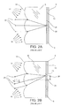
- Figure 2A depicts a side view of lenticular substrate 10, with an array of lenticular lenses 18. Only three lenses are shown.
- diffuse ambient illumination sources 14 and 16 in front of the lenticules passes through the lenses and clear substrate, it illuminates the image bearing layer 12 on the back surface 6 of the lenticular substrate 10.
- a cone of illumination will then reflect off diffusive reflective layer 8 and image point 20 of the image bearing layer 12 and back out through the lens.
- the image layer is at the focal distance of each lenticule, the light cone coming from any spot on the image layer, will emerge as a collimated beam 22 from the surface of the lens.
- Figure 2B depicts a different image point 26, which is at a distance 28 above the lens central axis. Because of this, the cone of light from image point 26, emerges from the lenticule at an angle 76, with respect to the lens central axis. Hence, it can readily been seen that image points 20 and 26 can be viewed through the same lenticule but at different view angles. When a viewer's eye is looking at a lenticular image, the particular image spot visible to the eye depends upon the angle of the eye's viewpoint with respect to the center line of the lenticular media. The ability of lenticular images to selectively see different image views at different viewing angles produces all the image effects such as autostereoscopic 3D, motion and collages. Discussions from this point on will focus on the type of lenticular images where the images are viewed with the lenticules oriented in the horizontal direction since this is the type of images that can be displayed with this invention.
- Figure 3 schematically represents how image data needs to be formatted behind each of the lenticules to produce a collage effect.
- there are three different source images consisting of a circle 30, a triangle 36 and a square 42. Each of these images has to be sampled in the vertical direction at the resolution of the final lenticular image. Since there are a total of nine lenticules on the media each image must be sampled to form lineform images of 9 lines.
- the source images are shown sampled to the left of the original images as circle 32, triangle 38 and square 44.
- the image sampling in the horizontal direction can be at a different resolution and is typically much higher. The sampling process is usually done today using digital scanning and image processing techniques to produce the lineform images.
- the three images have been sampled they then have to be formed into one composite image file to be printed onto the image bearing layer 12. This is done by interlacing the individual lines from each image. Since there are three source images there will be three image view lines behind each lenticule.
- the image data is then formatted so that the first line of each image is placed behind the first lenticule. As shown in Figure 3, line one of circle image data 32 is placed behind the first lenticule at image location 34. Line one of the second triangle image data 38 is placed behind the first lenticule at location 40, and line one of the third square image data 44 is placed behind the first lenticule at location 46.
- the second line of each image is then interlaced so that they fall behind the second lenticule. This is continued until all image lines from each source image have been interlaced.
- Figure 4 shows the rays 52 of the image views of the center image of triangle 20 converging to the viewer's eye 50 at the viewing distance 54 of the lenticular image.
- This convergence is caused by the fact that the image view lines are displaced from being centered on lenticule center lines 58 as the distance of the image view lines get farther from the lenticular image center.
- Figures 5A and 5B demonstrate how the rays from the image views of different pictures are made to converge to the viewer's eye at different viewing angles and at the correct viewing distance.
- Figure 5A shows the viewer's eye 50 with a viewing angle parallel to the lenticular image center line 70.
- the lenticular image card is shown sectioned into three parts: the upper 60, middle 64 and lower 68 sections. Each section is shown figuratively with two different image views consisting of triangular image point 20 and square image data 66 behind one lenticule. In reality, all the lenticules will have image data behind them. This was done to simplify the figures and explanatory text.
- a lenticular image card 62 is rotated in direction A in front of the viewer's eye 50.
- a different set of image views 74 located on the image bearing layer will become visible as rays 52 converge to the viewer's eye 50.
- a new viewing angle 72 is generated and the rays 52 of different image view lines converge to the viewer's eye 50.
- Figure 7A is the same as Figure 4, which was used to show how the rays 52 of image points 20 converge to the viewer's eye 50. If the viewer's eye 50 is replaced with a point source of illumination 56 as shown in Figure 7B, the rays emanating from illumination source 56 diverge to enter the lenticules of lenticular substrate 10. It can clearly be seen that these rays have a divergence angle that is the same as the convergence angle in Figure 7A. Therefore, the illumination from illumination source 56 after passing through the lenticules will illuminate the image view points 20 on the image bearing layer. This useful feature can be used to selectively illuminate a set of view lines belonging to only one picture which as shown in the Figure would be image data of the triangle.
- Figure 8A and 8B show in detail how two separate image views belonging to two separate pictures can be selectively illuminated by changing the angle of the source illumination relative to the center line of the lenticular image.
- rays 80 from an illumination source enter the lenticular side of the lenticular substrate and converge to image point 20 on the image bearing layer 12.
- Image bearing layer 12 being a of the transmissive type, allows rays 80 from an illumination source to pass through image point 20 as divergent rays 86 to be observed by viewer's eye 50. Since the rays 80 from an illumination source enter the lenticule at a specific angle they do not provide illumination for image spot 26. Hence, the image seen by viewer's eye 50 will be exclusively from image spot 20. As a consequence of viewing the image from the back instead of through the lenticules, the image data on the image bearing layer 12 must be reversed left to right in order to keep the correct orientation for the viewer.
- rays 84 from an illumination source provides a different angle of viewing 72 that enters lenticular lenses 18.
- the rays after entering a lenticule converge to image point 26 providing illumination exclusively to it.
- the emerging divergent rays 88 are observed by viewer's eye 50.
- Figure 9 shows an additional diffusive reflective layer 8 that can be added after the image bearing layer 12 to diffuse the emerging rays 90. Since the cone of illumination that converges to the image bearing layer is quite narrow the diffusive reflective layer 8 acts to increase the angle over which the image spot 26 can be observed without intensity falloff. Additionally, this diffusive layer also acts as a protective layer to prevent scratches to image bearing layer 12.
- Figures 10A, 10B and 10C illustrate how a lenticular image display can be configured to illuminate each image view individually for the a person viewing the images.
- the basic mechanism consists of the illumination source 94 which is positioned at the viewing distance and is made to move through an angle in the direction of arrow B, as shown in Figures 10A, 10B and 10C.
- the lenticular image has three different pictures and the image view 74 consists of a square, triangle and circle image data as figuratively shown. In fact the image data exists behind each of the lenticules, but for clarity is only shown behind three.
- the viewer's eye 50 views the lenticular image from the side opposite the illumination source.
- the observer's eye will see each of the pictures on the lenticular image in sequence, that is the square 96, the triangle 98 and the circle 102.
- the particular advantage of this being that the observers eye does not have to change its viewing position. Additionally, if more than one observer is looking at the display they will both simultaneously see the same image.
- FIG 11 An alternate method is shown in Figure 11, where instead of moving the light source through different viewing angles, individual illumination sources are positioned at the different viewing angles. As shown in Figure 11 there are three individual illumination sources at the viewing angles for the square 106, the triangle 108 and the circle 110. As each illumination source is individually turned on the image view associated with that viewing angle will be illuminated and become visible to the viewer's eye 50 at the opposite side of the lenticular image card.
- This method has the desirable feature that any one of the three image views can be illuminated in any order desired by turning on the illumination source associated with that particular view. Another desirable feature is that by gradually dropping the intensity of one illumination source while raising another, the effect of an image dissolve can be produced from any one image to any other.
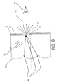
- FIG. 12 reveals further detail in the display device.
- the lenticular image card consisting of the clear lenticular substrate and image bearing layer 12 shown in perspective.
- the point illumination source is now shown as an array of illumination sources mounted on a support 114. Emanating from one of the illumination sources 112 is the diverging rays of light 48 which are directed to the lenticule side of the lenticular substrate 10. The diverging rays are focused by each of the lenticules down onto the particular image view that corresponds to the selected viewing angle, in this case the circle image data. The illumination of the selected image view then radiates out in the viewers direction.
- a line source of illumination 112 provides for more uniform illumination across each image view line, and consequentially provides much greater illumination for the whole display.
- the illumination source 112 is shown with the capability of translating through all viewing angles by its movement in the direction of arrow C.
- the individual illumination source 112 could be of any suitable type available today and could include LEDs, filament lamps or fiber optic bundles. It should be appreciated that the illumination source 112 although shown as an array of individual sources of illumination could be replaced directly with a line illumination source such as fluorescent tube or long filament lamp or any illumination source whose characteristics fulfill the requirements of the backlighted display device as set forth.
- the backlighted display device 118 is shown as having the ability to readily exchange lenticular image cards for viewing.
- the main body or frame 126 of the display is shown onto which is mounted a pivoted support lever 122 which holds the line illumination source at the correct viewing distance for the lenticular image.
- a second pivoted support lever is supplied on the opposite side to support the other end of the line illumination source.
- the lenticular image as previously described, being composed of the lenticular substrate 10 and image bearing layer 12.
- the pivoted support levers provide for the movement of the line illumination source 112, through all viewing angles of the lenticular image as it moves in the direction of arrow C.
- a flip up door 120, on the top of the display device allows for a lenticular image to be placed in the display by sliding the lenticular image card through the door in the direction D.
- the flip up door is supported by two hinges on both sides of the frame.
- the visible hinge 130 is shown mounting to frame 126 on a pivot 128.
- retaining tabs 124 which hold the lenticular image card in the display. Additionally, some retaining mechanism would be required to constrain the lenticular image card on the lenticule side also, but this is not shown. This could be a transparent glass or plastic window which is mounted securely to the display frame. Although not specifically shown in Figure 13, a plastic or glass cover on the front side of the display would also be desirable for protection of the lenticular image in the display.
- FIG 14 Another enhancement to the display device is illustrated in Figure 14 showing the display with two separate line illumination sources which can individually be moved to different viewing angles.
- This enhancement produces a display with two different illumination zones that provides for useful display characteristics.
- the outer display frame 126 is similar to the preceding figure.
- the line illumination source 112 is depicted being supported by the support levers 122 that holds the line illumination source 112 at the correct viewing distance and allows movement in the direction of arrow C.
- the length of the line illumination source is only half the width of the lenticular image card.
- the other half of the lenticular image card is illuminated with a different line illumination source 136, that has its own support layer 134 which can be moved through all viewing angles in the direction of arrow D.
- partition 138 In between the separate line illumination sources is partition 138 that provides the pivot point and support for the inner lever support arms for line illumination sources 136 and 112.
- partition 138 also acts as a baffle that divides the lenticular image card in half confining the illumination from each line illumination source to its half of the display.
- the image views on the lenticular image are also divided into halves as shown, half 142 and half 144 with the dividing center line 140 at the position of the partition 138.
- Each half of the lenticular image card has separate distinct picture information.
- the left half is shown figuratively with image information consisting of squares and inverted triangles, while the right half has image information figuratively represented by triangles and circles.
- each line illumination source can be moved independent of the other.
- the left half of the lenticular image card may be an animated motion sequence and the right half of the card a set of separate images which could contain text.
- the left line illumination source is moved continually back and forth through all viewing angles to generate the continuous animation sequence on the left of the lenticular image card.
- the right line illumination source is moved at a different rate to sequentially display the textual information in the image views on the right side of the lenticular image card. This type of display could be applied towards advertising displays.
- Figure 15 illustrates the two zone display device as seen from the top.
- the mechanisms of the two line illumination sources 136 and 112 can be clearly seen from this top view, where line illumination source 136 is raised to a higher position than 112.
- the partition 138 separating the two zones is also visible with the detail of the pivots for the support layers 134 and 122.
- the actual means used to move the line illumination sources could include any and all available types of mechanical displacement devices know in the art. Some examples of these devices will include: cams, pulleys, linear slides and lead screws.
- the actual motive force input to the mechanisms can be electric motors, solenoids and manual push pull actuators.
- the display as shown in Figures 14 and 15 provides two zone lenticular image viewing, but this is meant only as an example for the purpose of illustration. Display devices can use this principal to create multi zone illumination displays and with the proper illumination can provide upper and lower illumination zones.
- Figure 16A for comparative purposes again illustrates a cone of divergent illumination at position 148, which is at the correct viewing distance 54 for the lenticular image.
- the lenticular image is composed of clear lenticular substrate 10 and image bearing layer 12 and having image information figuratively shown as triangles and squares at two different sets of image views.
- the illumination when directed towards and through the lenticules of a lenticular image will have the illumination converge onto a set of image views corresponding to the viewing angle of the illumination source.
- a second illumination source at position 150 also at the correct viewing distance 54, will have its divergent rays of illumination converge on a second set of views corresponding to the viewing angle of the illumination.
- Figure 16B shows a lenticular image which has been created to have a viewing distance 54 at infinity.
- the only way to properly illuminate a given set of image views is to provide an illumination source that is effectively located at an infinite distance from the lenticules on the lenticular substrate. When illuminated in this way the rays from the illumination source will no longer diverge but will be parallel rays.
- One of the rays 152, of a set of parallel rays is shown as solid lines and proceeds from an illumination source at an infinite distance to the right at some angle.
- a second ray 154 of a set of parallel rays, shown as dashed lines, proceeds from an illumination source at an infinite distance to the right and is at a different angle. As each set of illumination rays enters the lenticules of the lenticular image at different viewing angles, they each selectively illuminate a different set of image views.
- Figure 17 illustrates an embodiment for an illumination source effectively located at infinity which has the ability to change the projected viewing angles of the parallel rays.
- the lenticular image consisting of lenticular substrate 10 and image bearing layer 12 are shown with image information on the image bearing layer 12 whose magnification produces a viewing distance at infinity.
- the illumination source consists of an array of cylinder lenses wherein the top cylinder lens 158 of the array is shown for reference. Since the features and operation of all the cylinder lenses are the same, a description of cylinder lens 158 will suffice. It should be understood that the long axis of the cylinder lens 158 and the cylinder lens array is oriented perpendicular to the plane of the figure. Behind cylinder lens 158 located at its back focal plane is an illumination source 160.
- Illumination source 160 is shown as a point source but in fact illumination source 160 is a line source whose line is parallel to the long axis of cylinder lens 158. Divergent illumination rays 162 from illumination 160 will pass through cylinder lens 158 and emerge from the other lens surface collimated as parallel rays 164. The angle 172 of the collimated rays of illumination is determined by the vertical position 168 relative to the center line 170 of the cylinder lens. The parallel rays 164 of the illumination source 160 then enter the lenticules of the clear lenticular substrate 10 and impinge on image bearing layer 12 to illuminate the set of image views pertaining to the square image information.
- a second similar illumination source 166 is shown at a different vertical position at the back focal plane of cylinder lens 158.
- the second illumination source 166 is shown as a dashed circle and the illumination rays 176 diverging from it are also dashed.
- the vertical position of the second illumination source 166 on the back focal plane of cylinder lens 158 is on the opposite side of the center line 170 of the cylinder lens 158 and therefore the angle of the parallel rays of illumination from this illumination source is also opposite.
Landscapes
- Engineering & Computer Science (AREA)
- Physics & Mathematics (AREA)
- Health & Medical Sciences (AREA)
- Manufacturing & Machinery (AREA)
- Ophthalmology & Optometry (AREA)
- Mechanical Engineering (AREA)
- General Physics & Mathematics (AREA)
- Optics & Photonics (AREA)
- Devices For Indicating Variable Information By Combining Individual Elements (AREA)
- Stereoscopic And Panoramic Photography (AREA)
- Illuminated Signs And Luminous Advertising (AREA)
Applications Claiming Priority (2)
| Application Number | Priority Date | Filing Date | Title |
|---|---|---|---|
| US930691 | 2001-08-15 | ||
| US09/930,691 US6574047B2 (en) | 2001-08-15 | 2001-08-15 | Backlit display for selectively illuminating lenticular images |
Publications (2)
| Publication Number | Publication Date |
|---|---|
| EP1286200A2 true EP1286200A2 (de) | 2003-02-26 |
| EP1286200A3 EP1286200A3 (de) | 2004-03-17 |
Family
ID=25459618
Family Applications (1)
| Application Number | Title | Priority Date | Filing Date |
|---|---|---|---|
| EP02078224A Withdrawn EP1286200A3 (de) | 2001-08-15 | 2002-08-05 | Anzeigevorrichtung mit Hintergrundbeleuchtung zur selektiven Beleuchtung lentikularer Bilder |
Country Status (4)
| Country | Link |
|---|---|
| US (1) | US6574047B2 (de) |
| EP (1) | EP1286200A3 (de) |
| JP (1) | JP2003195216A (de) |
| CN (1) | CN1407369A (de) |
Cited By (3)
| Publication number | Priority date | Publication date | Assignee | Title |
|---|---|---|---|---|
| WO2004086122A1 (en) * | 2003-03-27 | 2004-10-07 | David Harry Potts | Multi lens or lenticular display device |
| WO2012004216A1 (de) | 2010-07-09 | 2012-01-12 | Preh Gmbh | Verbesserte lentikular-leuchtvorrichtung |
| DE102016010383A1 (de) | 2016-08-30 | 2018-03-01 | Preh Gmbh | Verfahren zur Herstellung eines Lentikularfolienschichtaufbaus |
Families Citing this family (24)
| Publication number | Priority date | Publication date | Assignee | Title |
|---|---|---|---|---|
| AU777830B2 (en) * | 1999-07-08 | 2004-11-04 | Svyatoslav Ivanovich Arsenich | Projection system |
| JP4534337B2 (ja) * | 2000-10-19 | 2010-09-01 | ソニー株式会社 | 撮影装置及び撮影方法、並びに、画像生成装置及び画像生成方法 |
| AU2002239528A1 (en) | 2000-11-02 | 2002-05-27 | Taylor Corporation | Lenticular card and processes for making |
| US20040085260A1 (en) * | 2002-11-05 | 2004-05-06 | Mcdavid Louis C. | Multi-lingual display apparatus and method |
| US7857700B2 (en) * | 2003-09-12 | 2010-12-28 | Igt | Three-dimensional autostereoscopic image display for a gaming apparatus |
| US7529025B1 (en) * | 2004-03-29 | 2009-05-05 | Karterman Don S | Audio and visual display |
| TWI292502B (en) * | 2004-09-30 | 2008-01-11 | Hannstar Display Corp | Replaceable lamp set and direct backlight system fand lcd combination thereof |
| JP5377960B2 (ja) * | 2005-06-24 | 2013-12-25 | リアルディー インコーポレイテッド | オートステレオスコピックディスプレイシステム |
| US7878910B2 (en) | 2005-09-13 | 2011-02-01 | Igt | Gaming machine with scanning 3-D display system |
| US7483215B2 (en) * | 2006-08-28 | 2009-01-27 | Genie Lens Technologies, Llc | Reflective imaging assembly for displaying interlaced images |
| JP4753192B2 (ja) * | 2008-06-27 | 2011-08-24 | Nec液晶テクノロジー株式会社 | 位置合わせ用マーカ、それを用いた表示装置およびその製造方法 |
| US20100002006A1 (en) * | 2008-07-02 | 2010-01-07 | Cisco Technology, Inc. | Modal Multiview Display Layout |
| US20110063725A1 (en) * | 2009-09-17 | 2011-03-17 | Eyesaver International | Lenticular Display |
| JP2014113233A (ja) * | 2012-12-07 | 2014-06-26 | Olympia:Kk | 表示装置、遊技機、遊技媒体貸出機 |
| US9967546B2 (en) | 2013-10-29 | 2018-05-08 | Vefxi Corporation | Method and apparatus for converting 2D-images and videos to 3D for consumer, commercial and professional applications |
| US20150116458A1 (en) | 2013-10-30 | 2015-04-30 | Barkatech Consulting, LLC | Method and apparatus for generating enhanced 3d-effects for real-time and offline appplications |
| US10158847B2 (en) | 2014-06-19 | 2018-12-18 | Vefxi Corporation | Real—time stereo 3D and autostereoscopic 3D video and image editing |
| KR102415516B1 (ko) * | 2015-11-20 | 2022-07-01 | 에스엘 주식회사 | 차량용 램프 |
| RU2735480C2 (ru) * | 2016-06-14 | 2020-11-03 | Роллинг Оптикс Инновейшн АБ | Синтетическое изображение и способ его изготовления |
| JP6919673B2 (ja) | 2019-05-07 | 2021-08-18 | オムロン株式会社 | 表示切替装置 |
| JP2022141059A (ja) | 2021-03-15 | 2022-09-29 | オムロン株式会社 | 表示切替装置 |
| JP2022141058A (ja) * | 2021-03-15 | 2022-09-29 | オムロン株式会社 | 表示切替装置 |
| JP2023048869A (ja) | 2021-09-28 | 2023-04-07 | オムロン株式会社 | 表示切替装置、情報表示装置、遊技表示装置、およびスイッチ |
| CN115113416B (zh) * | 2022-07-22 | 2023-08-25 | 吉林省钜鸿智能技术有限公司 | 一种户外裸眼3d显示屏 |
Citations (4)
| Publication number | Priority date | Publication date | Assignee | Title |
|---|---|---|---|---|
| US4452509A (en) * | 1982-04-28 | 1984-06-05 | Rca Corporation | Projection television screen having a selected audience envelope |
| US4668080A (en) * | 1985-11-29 | 1987-05-26 | Rca Corporation | Method and apparatus for forming large area high resolution patterns |
| US4959641A (en) * | 1986-09-30 | 1990-09-25 | Bass Martin L | Display means for stereoscopic images |
| EP0570806A2 (de) * | 1992-05-19 | 1993-11-24 | Eastman Kodak Company | Verfahren und Vorrichtung zur Optimierung dreidimensionaler Bilder mittels Einstellung des Druckabstands |
Family Cites Families (6)
| Publication number | Priority date | Publication date | Assignee | Title |
|---|---|---|---|---|
| US3814513A (en) * | 1972-07-24 | 1974-06-04 | Dimensional Dev Corp | 3-d screen and system |
| GB2267579A (en) * | 1992-05-15 | 1993-12-08 | Sharp Kk | Optical device comprising facing lenticular or parallax screens of different pitch |
| GB2272555A (en) * | 1992-11-11 | 1994-05-18 | Sharp Kk | Stereoscopic display using a light modulator |
| US5647151A (en) * | 1994-04-01 | 1997-07-15 | Insight, Inc. | Multi-purpose image display systems |
| US6104452A (en) * | 1994-07-01 | 2000-08-15 | Adaptive Optics Associates, Inc. | Optical illuminator for liquid crystal displays |
| US6078424A (en) | 1998-07-13 | 2000-06-20 | Eastman Kodak Company | Apparatus for image display utilizing lenticular or barrier screens |
-
2001
- 2001-08-15 US US09/930,691 patent/US6574047B2/en not_active Expired - Lifetime
-
2002
- 2002-08-05 EP EP02078224A patent/EP1286200A3/de not_active Withdrawn
- 2002-08-13 JP JP2002236090A patent/JP2003195216A/ja active Pending
- 2002-08-15 CN CN02129825A patent/CN1407369A/zh active Pending
Patent Citations (4)
| Publication number | Priority date | Publication date | Assignee | Title |
|---|---|---|---|---|
| US4452509A (en) * | 1982-04-28 | 1984-06-05 | Rca Corporation | Projection television screen having a selected audience envelope |
| US4668080A (en) * | 1985-11-29 | 1987-05-26 | Rca Corporation | Method and apparatus for forming large area high resolution patterns |
| US4959641A (en) * | 1986-09-30 | 1990-09-25 | Bass Martin L | Display means for stereoscopic images |
| EP0570806A2 (de) * | 1992-05-19 | 1993-11-24 | Eastman Kodak Company | Verfahren und Vorrichtung zur Optimierung dreidimensionaler Bilder mittels Einstellung des Druckabstands |
Cited By (6)
| Publication number | Priority date | Publication date | Assignee | Title |
|---|---|---|---|---|
| WO2004086122A1 (en) * | 2003-03-27 | 2004-10-07 | David Harry Potts | Multi lens or lenticular display device |
| WO2012004216A1 (de) | 2010-07-09 | 2012-01-12 | Preh Gmbh | Verbesserte lentikular-leuchtvorrichtung |
| DE102010031192A1 (de) | 2010-07-09 | 2012-01-12 | Preh Gmbh | Lentikular-Leuchtvorrichtung |
| DE102010031192B4 (de) | 2010-07-09 | 2022-01-20 | Preh Gmbh | Lentikular-Leuchtvorrichtung und Bedienelement |
| DE102016010383A1 (de) | 2016-08-30 | 2018-03-01 | Preh Gmbh | Verfahren zur Herstellung eines Lentikularfolienschichtaufbaus |
| DE102016010383B4 (de) | 2016-08-30 | 2019-02-21 | Preh Gmbh | Verfahren zur Herstellung eines Lentikularfolienschichtaufbaus |
Also Published As
| Publication number | Publication date |
|---|---|
| US6574047B2 (en) | 2003-06-03 |
| JP2003195216A (ja) | 2003-07-09 |
| CN1407369A (zh) | 2003-04-02 |
| US20030035220A1 (en) | 2003-02-20 |
| EP1286200A3 (de) | 2004-03-17 |
Similar Documents
| Publication | Publication Date | Title |
|---|---|---|
| US6574047B2 (en) | Backlit display for selectively illuminating lenticular images | |
| Xia et al. | A 360-degree floating 3D display based on light field regeneration | |
| US9958694B2 (en) | Minimized-thickness angular scanner of electromagnetic radiation | |
| US6795241B1 (en) | Dynamic scalable full-parallax three-dimensional electronic display | |
| CN1926886B (zh) | 自动立体多用户显示器 | |
| US6999071B2 (en) | Method and apparatus for displaying 3d images | |
| US6922201B2 (en) | Chronological age altering lenticular image | |
| US7880945B2 (en) | Hologram projection screen and its manufacturing method and system as well as its applications | |
| US20070296920A1 (en) | Rear Projection Screen and Associated Display System | |
| JP2003140083A (ja) | 立体表示方法及びその装置 | |
| EP1004052A1 (de) | Gerät und verfahren zur erzeugung und darstellung virtueller, planarer abbildungen | |
| CN110062905A (zh) | 图像显示装置 | |
| Hong et al. | See-through multi-projection three-dimensional display using transparent anisotropic diffuser | |
| JP2007515666A (ja) | 二次元または三次元表示のための装置 | |
| Yoshida | Virtual multiplication of light sources for a 360°-viewable tabletop 3D display | |
| JP2008512709A (ja) | 画像の3次元表示と2次元表示を選択して行う組立物 | |
| Martinez et al. | Multi-user volumetric 360° display based on retro-reflective transparent surfaces | |
| Eichenlaub | Progress in autostereoscopic display technology at Dimension Technologies Inc. | |
| US7950805B2 (en) | Systems and methods for displaying images to viewers in motion or viewing from multiple perspectives | |
| JP2014153602A (ja) | 光学プレート及び空間画像表示装置 | |
| KR20020021105A (ko) | 입체경 시스템 | |
| JP4492208B2 (ja) | 三次元画像再生装置 | |
| KR200265369Y1 (ko) | 3차원 입체영상장치 | |
| Eichenlaub | Lightweight, compact 2D/3D autostereoscopic LCD backlight for games, monitor, and notebook applications | |
| WO2000035204A1 (en) | Dynamically scalable full-parallax stereoscopic display |
Legal Events
| Date | Code | Title | Description |
|---|---|---|---|
| PUAI | Public reference made under article 153(3) epc to a published international application that has entered the european phase |
Free format text: ORIGINAL CODE: 0009012 |
|
| AK | Designated contracting states |
Kind code of ref document: A2 Designated state(s): AT BE BG CH CY CZ DE DK EE ES FI FR GB GR IE IT LI LU MC NL PT SE SK TR Designated state(s): AT BE BG CH CY CZ DE DK EE ES FI FR GB GR IE IT LI LU MC NL PT SE SK TR |
|
| AX | Request for extension of the european patent |
Extension state: AL LT LV MK RO SI |
|
| PUAL | Search report despatched |
Free format text: ORIGINAL CODE: 0009013 |
|
| AK | Designated contracting states |
Kind code of ref document: A3 Designated state(s): AT BE BG CH CY CZ DE DK EE ES FI FR GB GR IE IT LI LU MC NL PT SE SK TR |
|
| AX | Request for extension of the european patent |
Extension state: AL LT LV MK RO SI |
|
| 17P | Request for examination filed |
Effective date: 20040816 |
|
| AKX | Designation fees paid |
Designated state(s): DE FR GB |
|
| GRAP | Despatch of communication of intention to grant a patent |
Free format text: ORIGINAL CODE: EPIDOSNIGR1 |
|
| STAA | Information on the status of an ep patent application or granted ep patent |
Free format text: STATUS: THE APPLICATION IS DEEMED TO BE WITHDRAWN |
|
| 18D | Application deemed to be withdrawn |
Effective date: 20050504 |