EP1285837A1 - Strukturgerippe einer Wagenkastenkonstruktion - Google Patents
Strukturgerippe einer Wagenkastenkonstruktion Download PDFInfo
- Publication number
- EP1285837A1 EP1285837A1 EP01810798A EP01810798A EP1285837A1 EP 1285837 A1 EP1285837 A1 EP 1285837A1 EP 01810798 A EP01810798 A EP 01810798A EP 01810798 A EP01810798 A EP 01810798A EP 1285837 A1 EP1285837 A1 EP 1285837A1
- Authority
- EP
- European Patent Office
- Prior art keywords
- profile
- longitudinal
- vertical
- frame
- profiles
- Prior art date
- Legal status (The legal status is an assumption and is not a legal conclusion. Google has not performed a legal analysis and makes no representation as to the accuracy of the status listed.)
- Granted
Links
Images



Classifications
-
- B—PERFORMING OPERATIONS; TRANSPORTING
- B62—LAND VEHICLES FOR TRAVELLING OTHERWISE THAN ON RAILS
- B62D—MOTOR VEHICLES; TRAILERS
- B62D33/00—Superstructures for load-carrying vehicles
- B62D33/04—Enclosed load compartments ; Frameworks for movable panels, tarpaulins or side curtains
- B62D33/044—Enclosed load compartments ; Frameworks for movable panels, tarpaulins or side curtains built up with profiles of constant elongated shape, e.g. extruded, mechanically interconnected by coupling members, e.g. by clamping, riveting or bolting
-
- B—PERFORMING OPERATIONS; TRANSPORTING
- B61—RAILWAYS
- B61D—BODY DETAILS OR KINDS OF RAILWAY VEHICLES
- B61D17/00—Construction details of vehicle bodies
- B61D17/04—Construction details of vehicle bodies with bodies of metal; with composite, e.g. metal and wood body structures
- B61D17/043—Construction details of vehicle bodies with bodies of metal; with composite, e.g. metal and wood body structures connections between superstructure sub-units
-
- B—PERFORMING OPERATIONS; TRANSPORTING
- B61—RAILWAYS
- B61D—BODY DETAILS OR KINDS OF RAILWAY VEHICLES
- B61D17/00—Construction details of vehicle bodies
- B61D17/04—Construction details of vehicle bodies with bodies of metal; with composite, e.g. metal and wood body structures
- B61D17/08—Sides
-
- F—MECHANICAL ENGINEERING; LIGHTING; HEATING; WEAPONS; BLASTING
- F16—ENGINEERING ELEMENTS AND UNITS; GENERAL MEASURES FOR PRODUCING AND MAINTAINING EFFECTIVE FUNCTIONING OF MACHINES OR INSTALLATIONS; THERMAL INSULATION IN GENERAL
- F16B—DEVICES FOR FASTENING OR SECURING CONSTRUCTIONAL ELEMENTS OR MACHINE PARTS TOGETHER, e.g. NAILS, BOLTS, CIRCLIPS, CLAMPS, CLIPS OR WEDGES; JOINTS OR JOINTING
- F16B2200/00—Constructional details of connections not covered for in other groups of this subclass
- F16B2200/40—Clamping arrangements where clamping parts are received in recesses of elements to be connected
-
- Y—GENERAL TAGGING OF NEW TECHNOLOGICAL DEVELOPMENTS; GENERAL TAGGING OF CROSS-SECTIONAL TECHNOLOGIES SPANNING OVER SEVERAL SECTIONS OF THE IPC; TECHNICAL SUBJECTS COVERED BY FORMER USPC CROSS-REFERENCE ART COLLECTIONS [XRACs] AND DIGESTS
- Y02—TECHNOLOGIES OR APPLICATIONS FOR MITIGATION OR ADAPTATION AGAINST CLIMATE CHANGE
- Y02T—CLIMATE CHANGE MITIGATION TECHNOLOGIES RELATED TO TRANSPORTATION
- Y02T30/00—Transportation of goods or passengers via railways, e.g. energy recovery or reducing air resistance
Definitions
- the present invention relates to a skeleton, in particular a structural skeleton, of a body construction, in particular for road or rail passenger transport vehicles, with a sidewall structure containing a car body interior facing Inside and an outside facing outward and cross-like joints forming longitudinal and vertical profiles.
- the sidewall structures of a skeleton for said carbody constructions become usually formed from longitudinal and vertical profiles running on their in usually cross-joint joints by means of welding, screws or rivets connected to each other.
- longitudinal profiles hereafter called longitudinal profiles
- longitudinal profile bars are in particular longitudinal profile bars, parapet profiles and belt profiles, such as floor, Pedestal, roof, and center straps, meant.
- vertical profiles below vertical profiles called, are in particular vertically running profile bars, profile posts, such as door jambs, Vertical columns, such as sidewall columns and window columns, meant.
- the window columns are arranged in the area of the window glazing and divide the window front into Segments or sections.
- the door jambs serve for the lateral limitation of the entry openings in the sidewall structure.
- Car body designs for omnibuses or buses of conventional design have mainly a with its outer contour flush running structural skeleton on which outside Cladding elements, such as aprons and panels, as well as the glazing of the window areas are attached.
- the mentioned longitudinal and vertical profiles of the sidewall structure are structural elements the carbody construction. They contribute significantly to the rigidity and strength of the body structure at. Accordingly, the requirements for the Connecting points between longitudinal and vertical profiles with respect to their mechanical properties.
- Common sidewall structures typically include roof straps running down the roof, Bodenierrtig running floor or base belts and vertically extending side wall posts. Further, the side wall structures further stiffen the carbody construction longitudinal profiles running between floor and roof straps, such as middle girth profiles or parapet profiles.
- the longitudinal and vertical profiles of the side wall structure are usually on the outside aligned in a plane, the so-called sidewall plane.
- the connection points between Longitudinal and vertical profiles are therefore usually designed as a crossstroke, i.e. one profile is interrupted at the connection point in each case and lies on the front side the continuous crossing profile.
- the two profiles are for example by means of corner joints screwed or welded together.
- a side wall structure In a first known embodiment of a side wall structure are the longitudinal profiles, namely the roof, center and floor belts at the joints with the vertical profiles, Namely the wall columns, designed as a continuous longitudinal profiles, which only are interrupted at the door openings.
- the vertical profiles are each at the joints interrupted, which with their front side in each case one longitudinal side of the Longitudinal profiles abut and screwed or welded by means of corner joints with these are.
- sidewall structures are known in which both the longitudinal profiles as also formed the vertical profiles of the cross-type joints throughout are, in this embodiment, the vertical profiles traverse the longitudinal profiles inside.
- this side wall structure does not form on the outside of an aligned plane and the vertical profiles must be in the event of a repair in consuming disassembly of her Rear crossing to be solved.
- it has been found that such sidewall structures have excessively large wall thicknesses, which due to legal regulations heavy in terms of maximum total vehicle width and minimum vehicle interior width to be realized.
- Object of the present invention is a skeleton of a car body construction with a To propose side wall structure, which is characterized by good strength and rigidity, a high installation and repair friendliness and characterized by a great design freedom.
- the object is achieved in that at one, several or all cross-type joints between longitudinal and vertical profile throughout the longitudinal profile is formed and the longitudinal profile of the vertical profile at least partially inside traversed behind and releasably connected to the vertical profile, and the longitudinal profile to the detachable Connection between longitudinal profile and vertical profile at least one in the profile longitudinal direction extending and the vertical profile trailing, undercut longitudinal groove contains.
- the one or more longitudinal profiles preferably contain one, two or more parallel, arranged on the outside and extending in the profile longitudinal undercut Longitudinal grooves or C-slots, wherein the undercut longitudinal grooves or the vertical profiles trailing behind at the cross-type joint (s) and inside Side surface of the or the vertical profiles abut.
- the aforementioned longitudinal grooves serve the detachable connection with the vertical profile.
- Longitudinal grooves means in the present description in the longitudinal direction of Profile and preferably parallel to the side edges extending grooves.
- the longitudinal and vertical profile are preferably at said cross-type joint connected by one or more screw connections, wherein the screw connection from a vertical profile or a connecting element passing through and in the threaded bore of a introduced into the undercut longitudinal groove of the longitudinal profile Einlageteils engaging screw.
- the insert part engages behind when tightened Screw the undercut longitudinal groove by clamping and thereby fix the vertical profile the longitudinal profile.
- the insert part is in this embodiment and in all subsequent inventive Embodiments and developments, which use said inserts, preferably a trained as a parallelogram and in the undercut longitudinal groove of the longitudinal profile swiveling plate or clamping piece.
- the insert part may further comprise one or more Have threaded holes for receiving one or more screws.
- the deposit part can also be in the form of an insert strip, in particular a prism-shaped insert strip, be executed, which is laterally inserted into the undercut groove.
- the inlay bar has one, preferably two or more bores, in particular threaded bores, for receiving one, preferably two or more, screw connections on.
- the insert strip can for example be dimensioned and arranged such that these the vertical profile traverses behind and arranged on both sides of the vertical profile screw receives.
- the vertical profile crosses the longitudinal profile without interruption, in which case the longitudinal profile completely traverses the vertical profile.
- the vertical profile may be interrupted at the cross-type joint, and with its front side abutting the longitudinal profile like a cross-piece, wherein the vertical profile at least partially overlaps the longitudinal profile, i. the longitudinal profile traverses the vertical profile at least partially and with at least one undercut longitudinal groove.
- the longitudinal profile contains in a preferred embodiment at least two parallel to the side wall plane running and running through a profile in the longitudinal direction gradation against each other perpendicular to the side wall plane offset outside side surfaces, wherein the Wagenkasteninneren offset side surface or side surfaces at least one undercut Contains longitudinal groove or contain and traverse the vertical profile or traverse behind, and the car body outside offset side surface with the outside Side surface of the vertical profile is aligned.
- the sidewall level is shared by the established aligned outside side surfaces of the vertical profiles.
- the vertical profiles can in this development via known corner connecting elements with the intersecting longitudinal profile be connected.
- the attachment is made by screw, with screws pass through the corner connecting element and engage in the threaded hole of the insert parts, which in the undercut longitudinal grooves of both the longitudinal profile and the Vertical profiles are introduced.
- the insert parts engage behind when the screw connection is tightened clamping the undercut longitudinal groove and thereby fix the vertical profile via Corner connecting element to the longitudinal profile.
- the corner connector is in this embodiment transverse, in particular perpendicular, oriented to the side wall plane.
- the corner connecting element can be designed as a corner piece or an angle piece.
- the Corner piece can be a cast, welded, forged or milled piece.
- the corner connector can also laterally in the embodiment of a slider inserted into the undercut groove be formed, wherein the corner connecting element engages behind the undercut groove, such that the corner element lies in the direction transverse to the insertion direction and through the groove longitudinal opening leading axis is fixed or anchored.
- the longitudinal and vertical profiles are for example by means of an extrusion or Pulltrusionsvons manufactured profiles.
- the longitudinal and vertical profiles are preferably made of metal such as iron or steel and in particular of a light metal such as aluminum and its Alloys.
- the profiles can also be made of formed sheets.
- the profiles mentioned can also be made of plastic, in particular of fiber-reinforced Be plastic.
- the profiles may also be hybrid profiles, which are made in the longitudinal direction composite, in particular glued, sub-profiles consist, with a first part profile of a metal, in particular aluminum and its alloys, and a second sub-profile of fiber-reinforced, in particular glass or carbon fiber reinforced, Plastic is.
- the longitudinal and vertical profiles can be open profiles, such as angle profiles or channel profiles, semi-open profiles or closed profiles, such as single or multi-chamber hollow profiles, be.
- the mentioned vertical profiles are in particular sidewall or window columns as well as door jambs.
- the longitudinal profiles are longitudinal profiles, forming an upper and lower termination of the sidewall structure, such as roof straps or Bodengurten or base belts.
- the longitudinal profiles can also be in the sidewall structure longitudinal profiles, such as middle straps or parapet straps.
- the belt profiles are preferably over the entire car body or vehicle length throughout i. trained without interruption.
- the belt profiles mentioned in particular the Mittelgurtprofile, but by case one or more door openings in the side wall structure to be interrupted.
- the belt profiles are preferably at least between the door openings continuously educated.
- the belt profiles can be connection points, in particular in the form of undercut Longitudinal grooves for fastening of interior fitting elements, such as lighting fixtures, cable strands, Piping, air ducts, covers or for mounting seat frames or vehicle components.
- connection points in particular in the form of undercut Longitudinal grooves for fastening of interior fitting elements, such as lighting fixtures, cable strands, Piping, air ducts, covers or for mounting seat frames or vehicle components.
- the roof, floor or base straps linear connection points for connection of roof or floor structures included.
- the belt profiles preferably have one over their longitudinal direction, in particular via their connection point, across uniform cross-sectional structure.
- the belt profiles included in built-in Condition at their intersecting with the vertical profiles joints preferably no cutouts and the like.
- Roof and / or floor or base belts may in cross-section of the invention angular longitudinal profiles or as longitudinal profiles with two at an angle, in particular be formed at a right angle to each other standing profile legs.
- One The first profile leg is preferably vertical and a second profile leg horizontal arranged, wherein the two profile legs on the outside one, preferably rectangular, Form recess for receiving the end portion of one or more vertical profiles.
- the two profile legs on the outside one, preferably rectangular, Form recess for receiving the end portion of one or more vertical profiles In a particularly preferred embodiment of the invention forms the aforementioned angle-like Longitudinal profile on the outside arranged with the outside side surface of the or Vertical profiles jointly aligned side surface. The mentioned side surface is located conveniently on the horizontal profile leg.
- novel, cross-type joints are preferably between balustrade and side wall or window pillars, between roof straps and window pillars or door jambs and between floor straps and sidewall pillars or door jambs.
- the side wall structure includes profiled straps in the Execution of a floor or a base belt, a middle or parapet belt, as well as a Roof boom. Transverse to these belt profiles are sidewall columns and window columns as well as door jambs provided.
- the cruciform connection between the middle or parapet belt and the sidewall columns or window columns are characterized in that the center or parapet belt at least one, two or more undercut longitudinal grooves has and is designed as a continuous longitudinal profile, which only by Door openings is interrupted.
- the center or parapet belt traverses the sidewall or window columns at least partially or completely, wherein at least one, two or several undercut longitudinal grooves traverse the side wall or window pillars.
- Mid or parapet belt is preferably formed as a flat profile, i. the profile width corresponds to at least twice the profile height.
- the center or parapet belt as a T-shaped hollow profile with a central, raised profile section and two-sided Be formed longitudinal grooves containing profile flanks.
- the side wall or window pillars can be considered in the region of said connection point continuous or interrupted vertical profiles may be formed, wherein in the first case the Center or parapet belt the side wall or window columns completely and in the second Fall partly behind.
- the attachment elements are in their height, so dimensioned, that their outer side surface are aligned with those of the vertical profiles together.
- the attachment elements are always arranged horizontally between two vertical profiles.
- the attachment elements found especially in the middle or parapet straps and if applicable for roof or floor or base belts application.
- the attachment elements can also contribute to the stiffening of the longitudinal profiles.
- the attachment element is preferably by means of this enforcing screws on the longitudinal profile fixed, wherein the screws engage in the threaded holes of insert parts, which in one or more parallel, undercut longitudinal grooves of the longitudinal profile are introduced.
- the attachment element can also by means of other connection techniques such as welding, riveting, latching or gluing be attached to the longitudinal profile.
- the attachment element can in a further embodiment of the invention at the same time corner connecting element between the longitudinal and vertical profile.
- the profile-like attachment element includes connection points, in particular groove-shaped connecting points, for receiving exterior cladding elements, in particular for the attachment of disc elements or of the Disc elements receiving rubber seals and / or cover elements.
- connection points can be formed as grooves, in particular undercut grooves be, which are suitable, said fasteners by insertion or To record latching.
- attachment element connection points for form-locking connections such as. Clip or plug connections have.
- the profile-like attachment element is preferably made of metal, such as iron or steel and in particular made of a light metal, such as aluminum and its alloys. Particularly suitable are extruded profiles made of a light metal, in particular aluminum or an aluminum alloy.
- the profile-like attachment element can also be made of plastic, especially made of fiber-reinforced, such as glass or carbon fiber reinforced plastic.
- the attachment element may consist of a solid profile, open profile, semi-open profile or closed Profile, such as single or multi-chamber hollow profile.
- Car body construction according to the invention finds particular application for buses, such as buses and, for example, low-floor buses.
- the car body construction is suitable for both intercity buses, e.g. Coaches, as well as for city buses, e.g. for the Public transport services.
- FIGS. 1a, 2a, 3a, 5a, 6a and 7a show sections of side wall structures according to the invention in cross-sectional view, wherein the cross-sectional planes perpendicular to the side wall plane are arranged.
- I is the outside of the car body (outside) and with II the car body inside (inside) marked.
- FIGS. 1b, 2b, 3b, 5b, FIGS. 6b and 7b show the associated cutouts of side wall structures according to the invention in side view, the side view from the outside to the side wall level towards the inside.
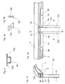
- Fig. 1a and 1b show the junction between a vertical post 101 and a Roof strap 1 according to a first embodiment of the invention.
- the roof strap 1 contains two outer side mutually parallel, undercut longitudinal grooves 2, with which the roof strap 1 traverses the vertical post 101.
- the longitudinal grooves 2 are the inside side surface of the vertical post 101 on.
- the vertical post 101 is as a formed profile containing two lateral profile flanks 102 (see Fig .. 4 and the associated Description), wherein the vertical post 101 by means of screw 3a, c to the Roof strap 1 is fixed.
- Attachment elements 14 fixed to the roof strap 1.
- the attachment elements 14 each extend between two vertical posts 101 and are by means of screw 3b on Roof strap 1 fixed.
- the outside side surface of the attachment elements 14 and the vertical post 101 form a common escape.
- the aforementioned screw 3a, b, c contain the attachment elements 14 and / or the profile flanks 102 piercing screws, which in the threaded hole in the Inserted longitudinal grooves 2 insert parts 121 are screwed (see Fig .. 9, 10 and to proper description).
- the side wall region according to FIG. 1a contains on the outside roof-facing cladding elements 125 and disc elements 123, which via the attachment elements 14 on the outer wall are attached.
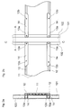
- Figs. 2a and 2b show the junction between a vertical post 101 and a Center belt 11 according to a first embodiment of the invention.
- the center belt 11 contains two outer side, peripherally arranged undercut longitudinal grooves 12 and traversed the vertical post 101 completely.
- the longitudinal grooves 12 are the inside Side surface of the vertical post 101 on.
- the vertical post 101 is as a two lateral Profile flanks 102 containing profile formed (see Fig. 4 and associated description).
- the vertical post 101 is via attachment elements 14 by means of screw 13a fixed to the center belt 11.
- the attachment elements 14 each extend between two vertical posts 101 and are by means of Bolt 3b on the center belt 11 set.
- the outside side surface the attachment elements 14 and the vertical post 101 form a common escape.
- the screw 13a, b contain the attachment elements 14 and the attachment elements 14 and profile edges 102 piercing screws, which in the threaded hole of inserted into the longitudinal grooves 12 insert parts 121 are screwed (see Fig .. 9, 10 and related description).
- the side wall region according to FIG. 2a contains on the outside disk elements 123 which extend over the upper side wall portion and in the region of the center belt 11th end and be replaced by subsequent cladding elements 124.
- the disk 123 and cladding elements 124 are above the attachment elements 14 on the outer wall attached.
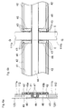
- Fig. 3a and 3b show the junction between a vertical post 101 and a Bodegurt 21 according to a first embodiment of the invention.
- the bottom strap 21 contains two outer side, peripherally arranged undercut longitudinal grooves 22 and trailing with these the vertical post 101.
- the longitudinal grooves 22 are the inside Side surface of the vertical post 101 on.
- the vertical post 101 is as a two lateral Profile flanks 102 containing profile formed (see Fig. 4 and associated description).
- the vertical post 101 is by means of the profile edges 102 piercing screw 23 fixed to the bottom strap 21.
- the vertical post 101 can also analogously to Fig. 1 and 2 via attachment elements on the bottom strap be set.
- the vertical profiles according to FIGS. 1 and 2 can be analogous to Fig. 3 be defined directly on their profile edges 102 on the longitudinal profile.
- the screw 23 contain the profile flanks 102 piercing screws, which in the threaded bore of introduced into the longitudinal grooves 22 insert parts 121st are screwed in (see Fig. 9, 10 and associated description).
- the side wall portion according to FIG. 3a contains on the outside cladding elements 124 Cladding elements 124 can be attached via attachment elements on the outer wall be.
- the vertical post 101 may, as shown in Fig. 4, as a hollow profile or as an open profile, like hat or omega-shaped profile, be formed.
- the vertical post contains, preferably two, lying in the same plane lateral profile edges or longitudinal strips 102nd Die Profile flanks 102 are formed, for example, in broadening of the inside side surface and lie parallel to the sidewall plane.
- the vertical post 101 is, for example made of an extruded aluminum section or a formed sheet metal.
- the vertical post 111 is in a further embodiment according to FIG. 8 as a hollow profile formed, with its transverse to the side wall plane side transverse surfaces depending an undercut longitudinal groove 112 included.
- Fig. 5a and 5b show the connection point between a vertical post 111 and a Roof strap 31 according to a second embodiment of the invention.
- the roof strap 31 includes a first, preferably elongated leg 37a, which with its outer side Side surface 39a arranged vertically or parallel to the vertical post 111 extending is.
- a second, preferably shortened, leg 37b is on the outside and its to the vertical post 111 facing side surface 39b horizontally or perpendicular to the vertical post 111, i. parallel to the end face of the vertical post 111 extending, wherein the formed by the two legs 37 a, 37 b angular recess for receiving of the vertical post or 111 is provided.
- the roof strap 31 includes two peripherally in the outer side surface 39a arranged undercut longitudinal grooves 32nd Der Roof strap 31 also includes a side surface 39b facing the vertical post 111 the second leg 37b arranged undercut longitudinal groove 34th
- the first leg 37a completely traverses the vertical post 111.
- the side surface 39a lies with its longitudinal grooves 32 of the inside side surface and the side surface 39b with its longitudinal groove 34 of the end face of the vertical post 111.
- the vertical post 111 is formed as a hollow profile (see Fig. 8 and associated description) and contains at its two transverse transverse to the side wall plane lateral surfaces one undercut longitudinal groove 112.
- the vertical post 111 is screw connections containing corner connecting elements 36 33 fixed to the roof strap 31. In Bodennachrtigen area of the junction are on both sides of the profile post 111 screw 33a arranged.
- the associated corner connecting elements 36a are in the longitudinal groove 32 of the first leg 37a and fixed in the longitudinal groove 112 of the vertical post 111. The fixation happens by each of the corner connecting element 36a piercing screws, which in the threaded bore screwed inserted into the longitudinal grooves 32, 112 insert parts 121 are (see Fig. 11 and the accompanying description).
- the two roof-side corner connecting elements 36b can also only in the Longitudinal grooves 32, 112 of the first leg 37a and the vertical post 111 anchored be.
- the roof straps 31 may further further, arranged inside undercut longitudinal grooves 35 for connecting further structures included.
- the side wall region according to FIG. 5a contains on the outside roof-facing disk elements 123, which are attached to the outer wall.
- Fig. 6a and 6b show the junction between a vertical post 111 and a Middle belt 41 according to a second embodiment of the invention.
- the center belt 41 is T-shaped and includes a central, raised, box-shaped profile member 44th and two lateral profile flanks 45a, 45b with recessed to the car body interior outside side surfaces.
- the center belt 41 forms uniformly aligned inside Side surface off.
- the vertical post 111 is divided into two profile parts 111a, 111b, wherein the middle belt 41st with its central profile part 44 between the two profile parts 111a, 111b leads and the two profile parts 111a, 111b with their end faces on the side abut the central profile part 44.
- the center belt 41 traverses with its two profile edges 45 a, 45 b and the associated longitudinal grooves 42, the inside side surface of the two profile parts 111a, 111b, whereby the longitudinal grooves 42 on the inside side surface the profile parts 111a, 111b come to rest.
- the vertical post 111 and the profile parts 111a, 111b are formed as hollow profiles (see. Fig. 8 and associated description) and included at their two transverse to the side wall plane extending side transverse surfaces each have an undercut longitudinal groove 112.
- the profile parts 111a, 111b are screw connections containing corner connecting elements 46 43 fixed to the center belt 41.
- the two sides of the profile parts 111a, 111b arranged corner connecting elements 46 are each both in a longitudinal groove 42, 112th a profile flank 45a, 45b and the profile part 111a, 111b as well as in the longitudinal groove 47 of the fixed central profile part 44.
- the fixation is done by each corner connecting element 46 piercing screws which into the threaded hole in the longitudinal grooves 42, 112, 47 inserted insert parts 121 are screwed.
- Figs. 7a and 7b show the junction between a vertical post 111 and a Bodice belt 51 according to a second embodiment of the invention.
- the bottom strap 51 includes a first, preferably elongated leg 57a, which with its outer side Side surface 59a arranged vertically or parallel to the vertical post 111 extending is.
- a second, preferably shortened, leg 57b is on the outside and its to the vertical post 111 facing side surface 59b horizontally or perpendicular to the vertical post 111 arranged, wherein the recess formed by the two legs 57 a, 57 b for Recording the or the vertical post 111 is provided.
- the bottom strap 51 includes a in the outer side side surface 59a of the first leg 57a in the dachissertigen area the junction arranged undercut longitudinal groove 52 and trailing with the outside side surface 59 a the vertical post 111 completely.
- the outside Side surface 59a may also have two undercut longitudinal grooves 52.
- the bottom strap 51 further includes a in the direction of the vertical post 111 side surface 59 b of second leg 57b arranged undercut longitudinal groove 54th
- the side surface 59a lies with its longitudinal groove 52 of the inside side surface and the side surface 59b with its longitudinal groove 54 on the end face of the vertical post 111.
- the vertical post 111 is formed as a hollow profile (see Fig. 8 and associated description) and contains at its two lateral transverse surfaces extending transversely to the side wall plane an undercut longitudinal groove 112.
- the vertical post 111 is screw connections containing corner connecting elements 56 53 fixed to the bottom strap 51. In the dachicartigen area of the junction On both sides of the vertical post 111 screw 53a are arranged.
- the associated corner connecting elements 56a are in the longitudinal groove 52 of the first leg 57a and fixed in the longitudinal groove 112 of the vertical post 111.
- the fixation happens through each of the corner connecting element 56 a piercing screws, which in the Threaded hole of inserted into the longitudinal grooves 52, 112 insert parts 121 screwed are (see Fig. 11 and the accompanying description).
- connection screw 53b In Boden maybertigen area of the connection screw 53b are arranged.
- the associated corner connecting elements 56b are in the longitudinal groove 112 of the vertical post 111 and fixed in the longitudinal groove 54 of the second leg 57b. The fixation happens by each corner connecting element 56b piercing screws, which in the threaded bore of introduced into the longitudinal grooves 112, 54 insert parts 121st are screwed in.
- the corner connecting element 56b is here therefore in a side wall plane arranged parallel plane.
- the said screw 53 contain the corner connecting element 56 piercing Screws which into the threaded hole in the undercut longitudinal grooves 52, 54, 112 introduced insert parts 121 are screwed.
- the crossing compound of the longitudinal and vertical profiles takes place in Roof area, middle section and in the bottom region of the side wall structure according to the Figures 1, 2, and 3 and the associated description.
- the intersecting connection of the longitudinal and vertical profiles takes place in the roof area, middle section and in the bottom region of the side wall structure according to FIGS. 4, 5 and 6 and the corresponding description.
- the sidewall structure can only be individual the crossing profile arrangements or profile connections described in FIGS contain.
- Fig. 9 shows a preferred embodiment of the insert part 121 of a screw according to the embodiments of FIGS. 1, 2, 3, 5, 6 and 7 in plan view (Fig. 9a) and Cross-sectional view (Fig. 9b).
- the insert part 121 is as a parallelogram-like plate formed with a centrally disposed threaded bore 122.
- To create the Screw connection becomes the first connection part 131, i. the vertical post or a connecting element, penetrating screw 134 in the threaded bore 122 of the Inserted part 121 screwed.
- the insert part 121 is with its longitudinal side in the undercut Longitudinal groove 133 of the second connecting part 132, i. of the longitudinal or belt profile, introduced.
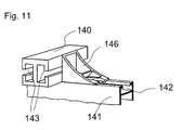
- Fig. 11 shows by way of example the construction of a connecting structure between a vertical post and longitudinal profile by means of corner connecting element, as shown for example in Fig. 5 and 7 is executed with the screw 33a, 53a.
- the vertical post 140 is from a longitudinal profile 141 with undercut longitudinal groove 142 completely behind.
- the vertical post 140 contains in the transverse to the side wall plane side surfaces each an undercut longitudinal groove 143.
- a corner connecting element 146 is located with one side surface the outside side surface of the longitudinal profile 141 and the lateral transverse surface of vertical post 140. Bolts pass through the corner connector 146 and the inserts in the two longitudinal grooves 142, 143 and connect in this way the Vertical post 140 with the longitudinal profile 141.
Landscapes
- Engineering & Computer Science (AREA)
- Mechanical Engineering (AREA)
- Life Sciences & Earth Sciences (AREA)
- Wood Science & Technology (AREA)
- Chemical & Material Sciences (AREA)
- Combustion & Propulsion (AREA)
- Transportation (AREA)
- Body Structure For Vehicles (AREA)
- Component Parts Of Construction Machinery (AREA)
- Working Measures On Existing Buildindgs (AREA)
- Vehicle Interior And Exterior Ornaments, Soundproofing, And Insulation (AREA)
- Rod-Shaped Construction Members (AREA)
Abstract
Description
- Fig. 1a:
- Querschnitt durch die Verbindungsstelle zwischen Vertikalpfosten und Dachgurt entlang der Linie B - B einer erfindungsgemässen Seitenwandstruktur gemäss Fig. 1b;
- Fig. 1b:
- Seitenansicht einer Verbindungsstelle zwischen Vertikalpfosten und Dachgurt;
- Fig. 2a:
- Querschnitt durch die Verbindungsstelle zwischen Vertikalpfosten und Mittelgurt entlang der Linie C - C einer erfindungsgemässen Seitenwandstruktur gemäss Fig. 2b;
- Fig. 2b:
- Seitenansicht einer Verbindungsstelle zwischen Vertikalpfosten und Mittelgurt;
- Fig. 3a:
- Querschnitt durch die Verbindungsstelle zwischen Vertikalpfosten und Bodengurt bzw. Sockelgurt entlang der Linie D - D einer erfindungsgemässen Seitenwandstruktur gemäss Fig. 3b;
- Fig. 3b:
- Seitenansicht einer Verbindungsstelle zwischen Vertikalpfosten und Bodengurt bzw. Sockelgurt;
- Fig. 4:
- Beispielhafter Querschnitt eines Vertikalpfostens entlang der Linie A - A gemäss Fig. 1, 2 und 3;
- Fig. 5a:
- Querschnitt durch die Verbindungsstelle zwischen Vertikalpfosten und Dachgurt entlang der Linie F - F einer weiteren erfindungsgemässen Seitenwandstruktur gemäss Fig. 5b;
- Fig. 5b:
- Seitenansicht einer Verbindungsstelle zwischen Vertikalpfosten und Dachgurt;
- Fig. 6a:
- Querschnitt durch die Verbindungsstelle zwischen Vertikalpfosten und Mittelgurt entlang der Linie G - G einer weiteren erfindungsgemässen Seitenwandstruktur gemäss Fig. 6b;
- Fig. 6b:
- Seitenansicht einer Verbindungsstelle zwischen Vertikalpfosten und Mittelgurt;
- Fig. 7a:
- Querschnitt durch die Verbindungsstelle zwischen Vertikalpfosten und Bodengurt bzw. Sockelgurt entlang der Linie H - H einer weiteren erfindungsgemässen Seitenwandstruktur gemäss Fig. 7b;
- Fig. 7b:
- Seitenansicht einer Verbindungsstelle zwischen Vertikalpfosten und Bodengurt bzw. Sockelgurt;
- Fig. 8:
- Beispielhafter Querschnitt eines Vertikalpfostens entlang der Linie E - E gemäss Fig. 5, 6 und 7;
- Fig. 9a:
- Aufsicht eines Einlageteils;
- Fig. 9b:
- Seitenansicht eines Einlageteils;
- Fig. 10:
- Querschnitt durch eine beispielhafte Schraubverbindung mit Einlageteil;
- Fig. 11:
- Perspektivische Ansicht einer Verbindung zwischen Vertikalprofil und Längsprofil mit Eckverbindungselementen.
Claims (22)
- Gerippe einer Wagenkastenkonstruktion, insbesondere für Strassen- oder Schienenfahrzeuge zur Personenbeförderung, mit einer Seitenwandstruktur, enthaltend eine zum Wagenkasteninneren gerichtete Innenseite und eine gegen aussen gerichtete Aussenseite sowie kreuzartige Verbindungsstellen ausbildende Längs- (1) und Vertikalprofile (101),
dadurch gekennzeichnet, dass
an einer, mehreren oder allen kreuzartigen Verbindungsstellen zwischen Längs- (1) und Vertikalprofil (101) das Längsprofil (1) durchgängig ausgebildet ist und das Längsprofil (1) das Vertikalprofil (101) wenigstens teilweise innenseitig hinterquert und mit dem Vertikalprofil (101) lösbar verbunden ist, und das Längsprofil (1) zur lösbaren Verbindung zwischen Längsprofil (1) und Vertikalprofil (101) wenigstens eine in Profillängsrichtung verlaufende und das Vertikalprofil (101) hinterquerende, hinterschnittene Längsnut (2) enthält. - Gerippe einer Wagenkastenkonstruktion nach Anspruch 1, dadurch gekennzeichnet, dass das Längsprofil (1) eine in Profillängsrichtung verlaufende hinterschnittene Längsnut (2) enthält und wenigstens die hinterschnittene Längsnut (2) das Vertikalprofil (101) innenseitig hinterquert und der innenseitigen Seitenfläche des Vertikalprofils (101) anliegt, und das Vertikalprofil (101) über wenigstens eine Schraubverbindung (3) mit dem Längsprofil (1) lösbar verbunden ist, und die Schraubverbindung (3) durch wenigstens eine das Vertikalprofil (101) oder ein Verbindungselement durchsetzende, in die Gewindebohrung eines in die hinterschnittene Längsnut (2) eingebrachten Einlageteils (121) eingreifende und das Einlageteil (121) verankernde Schraube ausgebildet ist.
- Gerippe einer Wagenkastenkonstruktion nach einem der Ansprüche 1 bis 2, dadurch gekennzeichnet, dass das Längsprofil (1) zwei oder mehrere parallel verlaufende, das Vertikalprofil (101) hinterquerende, hinterschnittene Längsnuten (2) zur lösbaren Verbindung mit dem Vertikalprofil (101) enthält.
- Gerippe einer Wagenkastenkonstruktion nach einem der Ansprüche 1 bis 3, dadurch gekennzeichnet, dass die Längs- (1) und Vertikalprofile (101) Strangpressprofile aus einem Leichtmetall, insbesondere aus Aluminium oder einer Aluminiumlegierung sind, und die Vertikalprofile eine Seitenwandsäulen, insbesondere Fensterpfosten und Türpfosten, und die Längsprofile Dach-, Mittel- und/oder Boden- bzw. Sockelgurten einer Seitenwandstruktur sind.
- Gerippe einer Wagenkastenkonstruktion nach einem der Ansprüche 1 bis 4, dadurch gekennzeichnet, dass das Vertikalprofil (101) in Verbreiterung der innenseitigen Seitenfläche angeordnete und parallel zur Seitenwandebene verlaufende seitliche Profilflanken (102) enthält.
- Gerippe einer Wagenkastenkonstruktion nach einem der Ansprüche 1 bis 4, dadurch gekennzeichnet, dass das Vertikalprofil (111) ein Hohlprofil ist und an seinen quer, vorzugsweise senkrecht zur Seitenwandebene liegenden Seitenquerflächen je eine hinterschnittene Längsnut (112) enthält.
- Gerippe einer Wagenkastenkonstruktion nach Anspruch 6, dadurch gekennzeichnet, dass das Vertikalprofil (111) mittels Eckverbindungselementen (36a, 36b) an das Längsprofil (31) festgelegt ist, wobei Schrauben die Eckverbindungselemente (36a, 36b) durchsetzen und in die Gewindebohrung (122) von Einlageteilen (121) eingreifen, welche in die hinterschnittenen Längsnuten (32, 112) sowohl des Längsprofils (31) als auch des Vertikalprofils (111) eingebracht sind.
- Gerippe einer Wagenkastenkonstruktion nach einem der Ansprüche 1 bis 7, dadurch gekennzeichnet, dass das Längsprofil (41) wenigstens zwei parallel zur Seitenwandebene verlaufende und durch eine in Profillängsrichtung verlaufende Abstufung gegeneinander und senkrecht zur Seitenwandebene versetzte aussenseitige Seitenflächen enthält, wobei die zum Wagenkasteninneren versetzte Seitenfläche oder Seitenflächen wenigstens eine hinterschnittene Längsnut (42) enthält oder enthalten und das Vertikalprofil (11a, 111b) hinterquert oder hinterqueren, und die zur Wagenkastenaussenseite versetzte Seitenfläche mit der aussenseitigen Seitenfläche des Vertikalprofils (111a, 111b) fluchtet.
- Gerippe einer Wagenkastenkonstruktion nach einem der Ansprüche 1 bis 8, dadurch gekennzeichnet, dass das Längsprofil (31) ein Dachgurt ist und der Dachgurt (31) einen ersten, vorzugsweise verlängerten Schenkel (37a), und einen zweiten, vorzugsweise verkürzten, aussenseitig angeordneten Schenkel (37b) enthält, und die beiden Schenkel (37a, 37b) eine winkelförmige Aussparung zur Aufnahme des Endabschnittes des Vertikalprofils (111) ausbilden, und der erste Schenkel (37a) und/oder der zweite Schenkel (37b) auf ihren zum Vertikalprofil (111) zugewandten Seitenflächen (39a, 39b) wenigstens eine hinterschnittene Längsnut (32, 34) zum Festlegen des Vertikalprofils (111) an den Dachgurt (31) mittels Eckverbindungselementen (36a, 36b) enthalten.
- Gerippe einer Wagenkastenkonstruktion nach Anspruch 6 und 9, dadurch gekennzeichnet, dass das Vertikalprofil (111) über ein oder zwei Eckverbindungselemente (36b) mit dem Dachgurt (31) verbunden ist, und das Eckverbindungselement (36b) sowohl am Vertikalprofil (111) als auch am ersten und zweiten Schenkel (37a, 37b) des Dachgurtes (31) festgelegt ist, wobei Schrauben das Eckverbindungselement (36b) durchsetzen und in die Gewindebohrung (122) von Einlageteilen (121) eingreifen, welche in die hinterschnittene Längsnuten (32, 34) des ersten (37a) und zweiten Schenkels (37b) und in die hinterschnittene Längsnut (112) des Vertikalprofils (111) eingebracht sind.
- Gerippe einer Wagenkastenkonstruktion nach einem der Ansprüche 1 bis 8, dadurch gekennzeichnet, dass das Längsprofil (51) ein Boden- oder Sockelgurt ist und der Boden- oder Sockelgurt (51) einen ersten, vorzugsweise verlängerten Schenkel (57a), und einen zweiten vorzugsweise verkürzten, aussenseitig angeordneten Schenkel (57b) enthält, und die beiden Schenkel (57a, 57b) eine winkelförmige Aussparung zur Aufnahme des Endabschnittes des Vertikalprofils (111) ausbilden, und der erste Schenkel (57a) und/oder der zweite Schenkel (57b) auf ihren zum Vertikalprofil (111) zugewandten Seitenflächen (59a, 59b) wenigstens eine hinterschnittene Längsnut (52, 54) zum Festlegen des Vertikalprofils (111) an den Bodengurt (51) mittels Eckverbindungselementen (56a, 56b) enthalten.
- Gerippe einer Wagenkastenkonstruktion nach Anspruch 6 und 11, dadurch gekennzeichnet, dass das Vertikalprofil (111) über ein oder zwei Eckverbindungselemente (56b) mit dem Boden- oder Sockelgurt (51) verbunden ist, und das Eckverbindungselement (56b) sowohl am Vertikalprofil (111) als auch am ersten und zweiten Schenkel (57a, 57b) des Boden- oder Sockelgurtes (51) festgelegt ist, wobei Schrauben das Eckverbindungselement (56b) durchsetzen und in die Gewindebohrung (122) von Einlageteilen (121) eingreifen, welche in die hinterschnittene Längsnuten (52, 54) des ersten (57a) und zweiten Schenkels (57b) und in die hinterschnittene Längsnut (112) des Vertikalprofils (111) eingebracht sind.
- Gerippe einer Wagenkastenkonstruktion nach einem der Ansprüche 1 bis 8, dadurch gekennzeichnet, dass das Längsprofil (41) ein Mittelgurt ist und der Mittelgurt (41) T-förmig ausgebildet ist und einen zentralen, erhöhten, kastenförmigen Profilteil (44) und zwei seitliche Profilflanken (45) mit zum Wagenkasteninneren versetzten aussenseitigen Seitenflächen enthalten, wobei in den aussenseitigen Seitenflächen der Profilflanken (45) wenigstens je eine hinterschnittene Längsnut (42) zum Festlegen des Vertikalprofils (111) an den Mittelgurt (41) ausgebildet ist und der Vertikalpfosten (111) an der Verbindungsstelle in zwei Profilteile (111a, 111b) geteilt ist, wobei der Mittelgurt (41) mit seinem zentralen Profilteil (44) zwischen den beiden Profilteilen (111a, 111b) hindurch führt und die beiden Profilteile (111a, 111b) mit ihren endseitigen Stirnflächen seitlich an den zentralen Profilteil (44) anstossen und der Mittelgurt (41) mit seinen beiden Profilflanken (45) die Profilteile (111a, 111b) hinterquert.
- Gerippe einer Wagenkastenkonstruktion nach Anspruch 6 und 13, dadurch gekennzeichnet, dass das Vertikalprofil (111) über Eckverbindungselemente (46) mit dem Mittelgurt (41) verbunden ist, und die Eckverbindungselemente (46) am Vertikalprofil (111), an den Profilflanken (45) und am zentralen Profilteil festgelegt sind, wobei Schrauben die Eckverbindungselemente (46) durchsetzen und in die Gewindebohrungen (122) von Einlageteilen (121) eingreifen, welche in die hinterschnittenen Längsnuten (112, 42, 47) des Vertikalprofils (111), der Profilflanken (45) und des zentralen Profilteils eingebracht sind.
- Gerippe einer Wagenkastenkonstruktion nach Anspruch 13, dadurch gekennzeichnet, dass die aussenseitigen Seitenflächen des zentralen Profilteils (44) und des Vertikalpfostens (111) gemeinsam fluchten.
- Gerippe einer Wagenkastenkonstruktion nach einem der Ansprüche 1 bis 7, dadurch gekennzeichnet, dass das das Längsprofil (11) kreuzende Vertikalprofil (101) durchgängig ausgebildet ist.
- Gerippe einer Wagenkastenkonstruktion nach einem der Ansprüche 1 bis 16, dadurch gekennzeichnet, dass zwischen zwei Vertikalprofilen (101) an der aussenseitigen Seitenfläche des Längsprofils (11) ein oder mehrere profilartige Aufsatzelemente (14) angebracht sind, wobei die aussenseitigen Seitenflächen der profilartigen Aufsatzelemente (14) und der Vertikalprofile (101) gemeinsam fluchten.
- Gerippe einer Wagenkastenkonstruktion nach Anspruch 17, dadurch gekennzeichnet, dass die profilartigen Aufsatzelemente (46) mittels das Aufsatzelement (46) durchsetzende und in die Gewindebohrung (122) von in die hinterschnittene Längsnut (12) oder Längsnuten des Längsprofils (11) eingebrachten Einlageteile (121) eingreifende Schrauben am Längsprofil (12) festgelegt sind.
- Gerippe einer Wagenkastenkonstruktion nach einem der Ansprüche 17 bis 18, dadurch gekennzeichnet, dass die profilartigen Aufsatzelemente (46) zugleich Eckverbindungselemente sind und das Vertikalprofil (101) wenigstens teilweise über die profilartigen Aufsatzelemente (46) an das Längsprofil (11) festgelegt ist.
- Gerippe einer Wagenkastenkonstruktion nach einem der Ansprüche 17 bis 19, dadurch gekennzeichnet, dass die profilartigen Aufsatzelemente (46) Anschlussstellen, insbesondere nutförmige Anschlussstellen, zur Befestigung von Scheibenelementen (123) und/oder Verkleidungsteilen (124, 125) enthalten.
- Gerippe einer Wagenkastenkonstruktion nach einem der Ansprüche 1 bis 20, dadurch gekennzeichnet, dass das Einlageteil (121) ein als Parallelogramm ausgebildetes und in die hinterschnittene Längsnut (133) einschwenkbares Klemmplättchen ist.
- Gerippe einer Wagenkastenkonstruktion nach einem der Ansprüche 1 bis 20, dadurch gekennzeichnet, dass das Einlageteil als ein in die hinterschnittene Längsnut seitlich einführbares und mehrere Schraubverbindungen aufnehmendes prismatisches Einlageteil, vorzugsweise Einlageleiste, ausgebildet ist.
Priority Applications (7)
| Application Number | Priority Date | Filing Date | Title |
|---|---|---|---|
| DE50106260T DE50106260D1 (de) | 2001-08-17 | 2001-08-17 | Strukturgerippe einer Wagenkastenkonstruktion |
| PT01810798T PT1285837E (pt) | 2001-08-17 | 2001-08-17 | Esqueleto de estrutura da construcao de uma carrocaria |
| EP01810798A EP1285837B1 (de) | 2001-08-17 | 2001-08-17 | Strukturgerippe einer Wagenkastenkonstruktion |
| ES01810798T ES2239116T3 (es) | 2001-08-17 | 2001-08-17 | Armazon estructural de una construccion de caja de coche. |
| AT01810798T ATE295795T1 (de) | 2001-08-17 | 2001-08-17 | Strukturgerippe einer wagenkastenkonstruktion |
| CA002394662A CA2394662C (en) | 2001-08-17 | 2002-07-24 | Structural frame of a vehicle superstructure |
| US10/223,189 US6695389B2 (en) | 2001-08-17 | 2002-08-16 | Structural frame of a vehicle superstructure |
Applications Claiming Priority (1)
| Application Number | Priority Date | Filing Date | Title |
|---|---|---|---|
| EP01810798A EP1285837B1 (de) | 2001-08-17 | 2001-08-17 | Strukturgerippe einer Wagenkastenkonstruktion |
Publications (2)
| Publication Number | Publication Date |
|---|---|
| EP1285837A1 true EP1285837A1 (de) | 2003-02-26 |
| EP1285837B1 EP1285837B1 (de) | 2005-05-18 |
Family
ID=8184095
Family Applications (1)
| Application Number | Title | Priority Date | Filing Date |
|---|---|---|---|
| EP01810798A Expired - Lifetime EP1285837B1 (de) | 2001-08-17 | 2001-08-17 | Strukturgerippe einer Wagenkastenkonstruktion |
Country Status (7)
| Country | Link |
|---|---|
| US (1) | US6695389B2 (de) |
| EP (1) | EP1285837B1 (de) |
| AT (1) | ATE295795T1 (de) |
| CA (1) | CA2394662C (de) |
| DE (1) | DE50106260D1 (de) |
| ES (1) | ES2239116T3 (de) |
| PT (1) | PT1285837E (de) |
Cited By (2)
| Publication number | Priority date | Publication date | Assignee | Title |
|---|---|---|---|---|
| WO2014000985A1 (de) * | 2012-06-27 | 2014-01-03 | Siemens Aktiengesellschaft | Wagenkasten |
| CN111688732A (zh) * | 2020-05-06 | 2020-09-22 | 中车青岛四方机车车辆股份有限公司 | 侧顶型材、轨道车辆车体及轨道车辆 |
Families Citing this family (13)
| Publication number | Priority date | Publication date | Assignee | Title |
|---|---|---|---|---|
| US7481486B2 (en) * | 2003-09-03 | 2009-01-27 | Specialty Vehicle Acquisition Corp. | Structural seat system for an automotive vehicle |
| US7246845B2 (en) * | 2003-09-03 | 2007-07-24 | Asc Incorporated | Structural seat system for an automotive vehicle |
| US7413240B2 (en) * | 2003-09-03 | 2008-08-19 | Specialty Vehicle Acquisition Corp. | Structural system for a convertible automotive vehicle |
| US20050046235A1 (en) * | 2003-09-03 | 2005-03-03 | Robertson James E. | Structural reinforcement system for an automotive vehicle |
| US7413242B2 (en) * | 2003-09-03 | 2008-08-19 | Specialty Vehicle Acquisition Corp. | Structural seat system for an automotive vehicle |
| USD543135S1 (en) | 2005-08-12 | 2007-05-22 | Asc Incorporated | Automotive vehicle and/or toy replica thereof |
| JP4531671B2 (ja) * | 2005-10-12 | 2010-08-25 | 株式会社神戸製鋼所 | 中空パネル及びその製造方法 |
| JP5019922B2 (ja) * | 2007-03-26 | 2012-09-05 | 株式会社小松製作所 | キャブ補強構造および作業機械用キャブ |
| CA2661721C (en) * | 2008-04-14 | 2016-06-28 | Fleet Engineers, Incorporated | Roll-up door assembly, blow molded panel therefor and method of making same |
| RU2502624C1 (ru) * | 2012-08-14 | 2013-12-27 | Открытое акционерное общество "МЕТРОВАГОНМАШ" | Кузов вагона метрополитена |
| CN103287509B (zh) * | 2013-06-24 | 2016-04-13 | 东风汽车公司 | 一种轻量化客车车身结构 |
| US9114730B1 (en) * | 2014-02-19 | 2015-08-25 | International Truck Intellectual Property Company, Llc | Seat mounting structure in vehicle floor frame |
| CN104477187B (zh) * | 2014-11-26 | 2018-01-12 | 中车南京浦镇车辆有限公司 | 低地板有轨电车车顶与侧墙连接结构 |
Citations (4)
| Publication number | Priority date | Publication date | Assignee | Title |
|---|---|---|---|---|
| US2247273A (en) * | 1934-03-26 | 1941-06-24 | Pullman Standard Car Mfg Co | Framing |
| EP0232832A2 (de) * | 1986-02-06 | 1987-08-19 | Iveco Magirus Aktiengesellschaft | Wagenkastengerippe |
| US5287813A (en) * | 1990-06-07 | 1994-02-22 | Alusuisse-Lonza Services Ltd. | Coach body construction for rail vehicles having extruded aluminum profiles with undercut nut-receiving grooves for ease of asssembly |
| EP0838384A1 (de) * | 1996-10-23 | 1998-04-29 | SLM Schweizerische Lokomotiv- und Maschinenfabrik AG | Fahrzeugkasten eines Schienenfahrzeuges und Schienenfahrzeug mit einem derartigen Fahrzeugkasten |
Family Cites Families (6)
| Publication number | Priority date | Publication date | Assignee | Title |
|---|---|---|---|---|
| US1236202A (en) * | 1917-05-21 | 1917-08-07 | Zouri Drawn Metals Company | Store-front construction. |
| US2345650A (en) * | 1940-10-12 | 1944-04-04 | Charles W Attwood | Skeletonized structure |
| CH681383A5 (de) * | 1990-04-11 | 1993-03-15 | Alusuisse Lonza Services Ag | |
| US5613726A (en) * | 1994-09-27 | 1997-03-25 | 4-Star Trailers, Inc. | Livestock trailer including improved trailer slat unit |
| GB9907597D0 (en) * | 1999-04-06 | 1999-05-26 | Robert Wright & Son Coachworks | Vehicle pillar system |
| DE59910461D1 (de) * | 1999-10-05 | 2004-10-14 | Alcan Tech & Man Ag | Baugruppenverbindung |
-
2001
- 2001-08-17 AT AT01810798T patent/ATE295795T1/de active
- 2001-08-17 EP EP01810798A patent/EP1285837B1/de not_active Expired - Lifetime
- 2001-08-17 PT PT01810798T patent/PT1285837E/pt unknown
- 2001-08-17 DE DE50106260T patent/DE50106260D1/de not_active Expired - Lifetime
- 2001-08-17 ES ES01810798T patent/ES2239116T3/es not_active Expired - Lifetime
-
2002
- 2002-07-24 CA CA002394662A patent/CA2394662C/en not_active Expired - Fee Related
- 2002-08-16 US US10/223,189 patent/US6695389B2/en not_active Expired - Lifetime
Patent Citations (4)
| Publication number | Priority date | Publication date | Assignee | Title |
|---|---|---|---|---|
| US2247273A (en) * | 1934-03-26 | 1941-06-24 | Pullman Standard Car Mfg Co | Framing |
| EP0232832A2 (de) * | 1986-02-06 | 1987-08-19 | Iveco Magirus Aktiengesellschaft | Wagenkastengerippe |
| US5287813A (en) * | 1990-06-07 | 1994-02-22 | Alusuisse-Lonza Services Ltd. | Coach body construction for rail vehicles having extruded aluminum profiles with undercut nut-receiving grooves for ease of asssembly |
| EP0838384A1 (de) * | 1996-10-23 | 1998-04-29 | SLM Schweizerische Lokomotiv- und Maschinenfabrik AG | Fahrzeugkasten eines Schienenfahrzeuges und Schienenfahrzeug mit einem derartigen Fahrzeugkasten |
Cited By (2)
| Publication number | Priority date | Publication date | Assignee | Title |
|---|---|---|---|---|
| WO2014000985A1 (de) * | 2012-06-27 | 2014-01-03 | Siemens Aktiengesellschaft | Wagenkasten |
| CN111688732A (zh) * | 2020-05-06 | 2020-09-22 | 中车青岛四方机车车辆股份有限公司 | 侧顶型材、轨道车辆车体及轨道车辆 |
Also Published As
| Publication number | Publication date |
|---|---|
| DE50106260D1 (de) | 2005-06-23 |
| US20030034671A1 (en) | 2003-02-20 |
| ATE295795T1 (de) | 2005-06-15 |
| CA2394662A1 (en) | 2003-02-17 |
| ES2239116T3 (es) | 2005-09-16 |
| US6695389B2 (en) | 2004-02-24 |
| PT1285837E (pt) | 2005-08-31 |
| EP1285837B1 (de) | 2005-05-18 |
| CA2394662C (en) | 2007-05-08 |
Similar Documents
| Publication | Publication Date | Title |
|---|---|---|
| EP1285837B1 (de) | Strukturgerippe einer Wagenkastenkonstruktion | |
| EP0608761B1 (de) | Wagenkastenaufbau, insbesondere für Eisenbahnwagen zur Personenbeförderung | |
| EP0465427B1 (de) | Wagenkastenaufbau für Schienenfahrzeuge | |
| DE69801225T2 (de) | Fahrgestell | |
| EP0152110A2 (de) | Randschiene für eine Scheibe, insbesondere einer Ganzglastüre | |
| DE102012204713A1 (de) | Ladeboden sowie Profilelement für einen Ladeboden | |
| DE102010014962A1 (de) | Außenwand für einen Schienenfahrzeug-Wagenkasten und Verfahren zu dessen Herstellung | |
| DE69616388T2 (de) | Aufzugskabinenraum | |
| DE4014385A1 (de) | Fahrzeugkarosserie | |
| DE4128234C1 (de) | ||
| EP0657610B1 (de) | Bodenschwelle bzw. Abdeckprofil für Blendrahmen von Schiebe- oder Hebe-Schiebefenstern und -türen od.dgl. | |
| DE69219286T2 (de) | Fahrzeugaufbau mit Verbundseitenwänden | |
| EP0685381A1 (de) | Kabine für Fahrzeuge und Gerätschaften | |
| EP0185678A1 (de) | Wagenkastenaufbau. | |
| CH663067A5 (de) | Wagenkastenaufbau, insbesondere fuer strassen- oder schienenfahrzeuge. | |
| DE68903348T2 (de) | Aufbauten vom typ sattelauflieger mit plane. | |
| DE69407014T2 (de) | Aluminium-Aufbauten für Nutzfahrzeuge | |
| EP0647476A1 (de) | Wandkonstruktion für eine Kabine einer Lackieranlage | |
| DE3424690C2 (de) | Selbsttragende Omnibus-Karosserie | |
| EP0838384A1 (de) | Fahrzeugkasten eines Schienenfahrzeuges und Schienenfahrzeug mit einem derartigen Fahrzeugkasten | |
| EP0755838B1 (de) | Gerippestruktur mit Türrahmen und Wandelementen | |
| DE1630621A1 (de) | Kastenaufbau fuer Lastfahrzeuge | |
| AT524864A4 (de) | Seitenwand für ein Schienenfahrzeug | |
| DE19949372C2 (de) | Rahmenkonstruktion und Verbindungselement hierfür | |
| DE10041899A1 (de) | Omnibus mit einem Podest im Passagierraum |
Legal Events
| Date | Code | Title | Description |
|---|---|---|---|
| PUAI | Public reference made under article 153(3) epc to a published international application that has entered the european phase |
Free format text: ORIGINAL CODE: 0009012 |
|
| AK | Designated contracting states |
Kind code of ref document: A1 Designated state(s): AT BE CH CY DE DK ES FI FR GB GR IE IT LI LU MC NL PT SE TR Designated state(s): AT BE CH CY DE DK ES FI FR GB GR IE IT LI LU MC NL PT SE TR |
|
| AX | Request for extension of the european patent |
Extension state: AL LT LV MK RO SI |
|
| 17P | Request for examination filed |
Effective date: 20030826 |
|
| AKX | Designation fees paid |
Designated state(s): AT BE CH CY DE DK ES FI FR GB GR IE IT LI LU MC NL PT SE TR |
|
| AXX | Extension fees paid |
Extension state: SI Payment date: 20030826 |
|
| 17Q | First examination report despatched |
Effective date: 20031219 |
|
| GRAP | Despatch of communication of intention to grant a patent |
Free format text: ORIGINAL CODE: EPIDOSNIGR1 |
|
| GRAS | Grant fee paid |
Free format text: ORIGINAL CODE: EPIDOSNIGR3 |
|
| GRAA | (expected) grant |
Free format text: ORIGINAL CODE: 0009210 |
|
| DAX | Request for extension of the european patent (deleted) | ||
| RBV | Designated contracting states (corrected) |
Designated state(s): AT BE CH DE ES FR GB IE IT LI LU MC NL PT SE TR |
|
| AK | Designated contracting states |
Kind code of ref document: B1 Designated state(s): AT BE CH DE ES FR GB IE IT LI LU MC NL PT SE TR |
|
| REG | Reference to a national code |
Ref country code: GB Ref legal event code: FG4D Free format text: NOT ENGLISH |
|
| REG | Reference to a national code |
Ref country code: SE Ref legal event code: TRGR |
|
| REG | Reference to a national code |
Ref country code: CH Ref legal event code: EP |
|
| GBT | Gb: translation of ep patent filed (gb section 77(6)(a)/1977) |
Effective date: 20050518 |
|
| REG | Reference to a national code |
Ref country code: IE Ref legal event code: FG4D Free format text: LANGUAGE OF EP DOCUMENT: GERMAN |
|
| REF | Corresponds to: |
Ref document number: 50106260 Country of ref document: DE Date of ref document: 20050623 Kind code of ref document: P |
|
| REG | Reference to a national code |
Ref country code: PT Ref legal event code: SC4A Effective date: 20050621 |
|
| REG | Reference to a national code |
Ref country code: ES Ref legal event code: FG2A Ref document number: 2239116 Country of ref document: ES Kind code of ref document: T3 |
|
| ET | Fr: translation filed | ||
| PLBE | No opposition filed within time limit |
Free format text: ORIGINAL CODE: 0009261 |
|
| STAA | Information on the status of an ep patent application or granted ep patent |
Free format text: STATUS: NO OPPOSITION FILED WITHIN TIME LIMIT |
|
| 26N | No opposition filed |
Effective date: 20060221 |
|
| PGFP | Annual fee paid to national office [announced via postgrant information from national office to epo] |
Ref country code: MC Payment date: 20070801 Year of fee payment: 7 |
|
| PGFP | Annual fee paid to national office [announced via postgrant information from national office to epo] |
Ref country code: LU Payment date: 20070905 Year of fee payment: 7 |
|
| PG25 | Lapsed in a contracting state [announced via postgrant information from national office to epo] |
Ref country code: MC Free format text: LAPSE BECAUSE OF NON-PAYMENT OF DUE FEES Effective date: 20080831 |
|
| PG25 | Lapsed in a contracting state [announced via postgrant information from national office to epo] |
Ref country code: LU Free format text: LAPSE BECAUSE OF NON-PAYMENT OF DUE FEES Effective date: 20080817 |
|
| PGFP | Annual fee paid to national office [announced via postgrant information from national office to epo] |
Ref country code: AT Payment date: 20100803 Year of fee payment: 10 |
|
| REG | Reference to a national code |
Ref country code: CH Ref legal event code: NV Representative=s name: NOVAGRAAF SWITZERLAND S.A. Ref country code: CH Ref legal event code: PUE Owner name: CONSTELLIUM SWITZERLAND AG (LTD, SA) Free format text: ALCAN TECHNOLOGY & MANAGEMENT AG#BADISCHE BAHNHOFSTRASSE 16#8212 NEUHAUSEN AM RHEINFALL (CH) -TRANSFER TO- CONSTELLIUM SWITZERLAND AG (LTD, SA)#MAX HOEGGER-STRASSE 6#8048 ZUERICH (CH) |
|
| BECN | Be: change of holder's name |
Owner name: CONSTELLIUM SWITZERLAND A.G. Effective date: 20110906 |
|
| REG | Reference to a national code |
Ref country code: NL Ref legal event code: SD Effective date: 20111214 Ref country code: NL Ref legal event code: TD Effective date: 20111214 |
|
| REG | Reference to a national code |
Ref country code: FR Ref legal event code: TP Owner name: CONSTELLIUM SWITZERLAND AG, CH Effective date: 20111130 Ref country code: FR Ref legal event code: CD Owner name: CONSTELLIUM SWITZERLAND AG, CH Effective date: 20111130 |
|
| REG | Reference to a national code |
Ref country code: PT Ref legal event code: PC4A Owner name: ALCAN FINANCES SWITZERLAND AG, CH Effective date: 20120118 |
|
| REG | Reference to a national code |
Ref country code: ES Ref legal event code: PC2A Owner name: CONSTELLIUM SWITZERLAND AG Effective date: 20120228 |
|
| REG | Reference to a national code |
Ref country code: DE Ref legal event code: R081 Ref document number: 50106260 Country of ref document: DE Owner name: CONSTELLIUM SWITZERLAND AG, CH Free format text: FORMER OWNER: ALCAN TECHNOLOGY MANAGEMENT AG, NEUHAUSEN AM RHEINFALL, CH Effective date: 20120302 Ref country code: DE Ref legal event code: R081 Ref document number: 50106260 Country of ref document: DE Owner name: CONSTELLIUM SWITZERLAND AG, CH Free format text: FORMER OWNER: ALCAN TECHNOLOGY & MANAGEMENT AG, NEUHAUSEN AM RHEINFALL, CH Effective date: 20120302 |
|
| REG | Reference to a national code |
Ref country code: CH Ref legal event code: PCAR Free format text: NOVAGRAAF SWITZERLAND SA;CHEMIN DE L'ECHO 3;1213 ONEX (CH) |
|
| REG | Reference to a national code |
Ref country code: GB Ref legal event code: 732E Free format text: REGISTERED BETWEEN 20120510 AND 20120516 |
|
| REG | Reference to a national code |
Ref country code: AT Ref legal event code: MM01 Ref document number: 295795 Country of ref document: AT Kind code of ref document: T Effective date: 20110817 |
|
| PG25 | Lapsed in a contracting state [announced via postgrant information from national office to epo] |
Ref country code: AT Free format text: LAPSE BECAUSE OF NON-PAYMENT OF DUE FEES Effective date: 20110817 |
|
| REG | Reference to a national code |
Ref country code: FR Ref legal event code: PLFP Year of fee payment: 16 |
|
| REG | Reference to a national code |
Ref country code: FR Ref legal event code: PLFP Year of fee payment: 17 |
|
| REG | Reference to a national code |
Ref country code: FR Ref legal event code: PLFP Year of fee payment: 18 |
|
| PGFP | Annual fee paid to national office [announced via postgrant information from national office to epo] |
Ref country code: NL Payment date: 20190826 Year of fee payment: 19 |
|
| PGFP | Annual fee paid to national office [announced via postgrant information from national office to epo] |
Ref country code: SE Payment date: 20190828 Year of fee payment: 19 Ref country code: IE Payment date: 20190827 Year of fee payment: 19 Ref country code: DE Payment date: 20190828 Year of fee payment: 19 Ref country code: PT Payment date: 20190801 Year of fee payment: 19 Ref country code: TR Payment date: 20190801 Year of fee payment: 19 Ref country code: FR Payment date: 20190826 Year of fee payment: 19 Ref country code: IT Payment date: 20190826 Year of fee payment: 19 |
|
| PGFP | Annual fee paid to national office [announced via postgrant information from national office to epo] |
Ref country code: BE Payment date: 20190827 Year of fee payment: 19 |
|
| PGFP | Annual fee paid to national office [announced via postgrant information from national office to epo] |
Ref country code: GB Payment date: 20190827 Year of fee payment: 19 |
|
| PGFP | Annual fee paid to national office [announced via postgrant information from national office to epo] |
Ref country code: CH Payment date: 20190903 Year of fee payment: 19 |
|
| PGFP | Annual fee paid to national office [announced via postgrant information from national office to epo] |
Ref country code: ES Payment date: 20200901 Year of fee payment: 20 |
|
| REG | Reference to a national code |
Ref country code: DE Ref legal event code: R119 Ref document number: 50106260 Country of ref document: DE |
|
| REG | Reference to a national code |
Ref country code: SE Ref legal event code: EUG |
|
| REG | Reference to a national code |
Ref country code: CH Ref legal event code: PL |
|
| REG | Reference to a national code |
Ref country code: NL Ref legal event code: MM Effective date: 20200901 |
|
| GBPC | Gb: european patent ceased through non-payment of renewal fee |
Effective date: 20200817 |
|
| PG25 | Lapsed in a contracting state [announced via postgrant information from national office to epo] |
Ref country code: CH Free format text: LAPSE BECAUSE OF NON-PAYMENT OF DUE FEES Effective date: 20200831 Ref country code: LI Free format text: LAPSE BECAUSE OF NON-PAYMENT OF DUE FEES Effective date: 20200831 Ref country code: PT Free format text: LAPSE BECAUSE OF NON-PAYMENT OF DUE FEES Effective date: 20210317 |
|
| REG | Reference to a national code |
Ref country code: BE Ref legal event code: MM Effective date: 20200831 |
|
| PG25 | Lapsed in a contracting state [announced via postgrant information from national office to epo] |
Ref country code: SE Free format text: LAPSE BECAUSE OF NON-PAYMENT OF DUE FEES Effective date: 20200818 |
|
| PG25 | Lapsed in a contracting state [announced via postgrant information from national office to epo] |
Ref country code: FR Free format text: LAPSE BECAUSE OF NON-PAYMENT OF DUE FEES Effective date: 20200831 Ref country code: DE Free format text: LAPSE BECAUSE OF NON-PAYMENT OF DUE FEES Effective date: 20210302 |
|
| PG25 | Lapsed in a contracting state [announced via postgrant information from national office to epo] |
Ref country code: GB Free format text: LAPSE BECAUSE OF NON-PAYMENT OF DUE FEES Effective date: 20200817 Ref country code: IE Free format text: LAPSE BECAUSE OF NON-PAYMENT OF DUE FEES Effective date: 20200817 Ref country code: BE Free format text: LAPSE BECAUSE OF NON-PAYMENT OF DUE FEES Effective date: 20200831 |
|
| PG25 | Lapsed in a contracting state [announced via postgrant information from national office to epo] |
Ref country code: NL Free format text: LAPSE BECAUSE OF NON-PAYMENT OF DUE FEES Effective date: 20200901 |
|
| REG | Reference to a national code |
Ref country code: ES Ref legal event code: FD2A Effective date: 20211129 |
|
| PG25 | Lapsed in a contracting state [announced via postgrant information from national office to epo] |
Ref country code: PT Free format text: LAPSE BECAUSE OF EXPIRATION OF PROTECTION Effective date: 20210825 |
|
| PG25 | Lapsed in a contracting state [announced via postgrant information from national office to epo] |
Ref country code: ES Free format text: LAPSE BECAUSE OF EXPIRATION OF PROTECTION Effective date: 20210818 |
|
| PG25 | Lapsed in a contracting state [announced via postgrant information from national office to epo] |
Ref country code: IT Free format text: LAPSE BECAUSE OF NON-PAYMENT OF DUE FEES Effective date: 20200817 |
|
| PG25 | Lapsed in a contracting state [announced via postgrant information from national office to epo] |
Ref country code: TR Free format text: LAPSE BECAUSE OF NON-PAYMENT OF DUE FEES Effective date: 20200817 |
|
| PG25 | Lapsed in a contracting state [announced via postgrant information from national office to epo] |
Ref country code: PT Free format text: LAPSE BECAUSE OF NON-PAYMENT OF DUE FEES Effective date: 20200917 |
|
| PG25 | Lapsed in a contracting state [announced via postgrant information from national office to epo] |
Ref country code: PT Free format text: LAPSE BECAUSE OF NON-PAYMENT OF DUE FEES Effective date: 20200917 |