EP1284229B1 - Procédé et appareil de manipulation des feuilles de verre - Google Patents
Procédé et appareil de manipulation des feuilles de verre Download PDFInfo
- Publication number
- EP1284229B1 EP1284229B1 EP02018069A EP02018069A EP1284229B1 EP 1284229 B1 EP1284229 B1 EP 1284229B1 EP 02018069 A EP02018069 A EP 02018069A EP 02018069 A EP02018069 A EP 02018069A EP 1284229 B1 EP1284229 B1 EP 1284229B1
- Authority
- EP
- European Patent Office
- Prior art keywords
- glass
- cutting
- panels
- residual
- glass blank
- Prior art date
- Legal status (The legal status is an assumption and is not a legal conclusion. Google has not performed a legal analysis and makes no representation as to the accuracy of the status listed.)
- Expired - Lifetime
Links
Images


Classifications
-
- C—CHEMISTRY; METALLURGY
- C03—GLASS; MINERAL OR SLAG WOOL
- C03B—MANUFACTURE, SHAPING, OR SUPPLEMENTARY PROCESSES
- C03B33/00—Severing cooled glass
- C03B33/02—Cutting or splitting sheet glass or ribbons; Apparatus or machines therefor
- C03B33/023—Cutting or splitting sheet glass or ribbons; Apparatus or machines therefor the sheet or ribbon being in a horizontal position
- C03B33/03—Glass cutting tables; Apparatus for transporting or handling sheet glass during the cutting or breaking operations
-
- B—PERFORMING OPERATIONS; TRANSPORTING
- B65—CONVEYING; PACKING; STORING; HANDLING THIN OR FILAMENTARY MATERIAL
- B65G—TRANSPORT OR STORAGE DEVICES, e.g. CONVEYORS FOR LOADING OR TIPPING, SHOP CONVEYOR SYSTEMS OR PNEUMATIC TUBE CONVEYORS
- B65G49/00—Conveying systems characterised by their application for specified purposes not otherwise provided for
- B65G49/05—Conveying systems characterised by their application for specified purposes not otherwise provided for for fragile or damageable materials or articles
- B65G49/06—Conveying systems characterised by their application for specified purposes not otherwise provided for for fragile or damageable materials or articles for fragile sheets, e.g. glass
- B65G49/068—Stacking or destacking devices; Means for preventing damage to stacked sheets, e.g. spaces
Definitions
- the invention relates to a method and a device for Editing glass panels.
- insulating glass glass boards are used on cutting machines Single panes cut for insulating glass units. Insulating are composed of at least two discs, consisting of a first outer disc, which usually coated, and a second inner disc, which is uncoated.
- a glass raw board which is coated, one Cutting system supplied and there according to a predetermined Cutting program divided into individual slices.
- the glass raw boards have e.g. a length of 6.0 m and a width of 3.21 m up.
- the division of glass panels is done by Cutting or scratches, creating a predetermined breaking point and then breaking. In a so-called crushing plant is transverse to the longitudinal extent of the glass raw plate and in a subsequent automated so-called X and Y crushing plant or manually in longitudinal directions of the glass raw plate Broken. It fall on residual glass panels.
- a processing line for splitting usually has the modules storage, feeding, cutting, breaking and sorting / storage on.
- Residual glass panels are usually passed on by single cutting machines processed. The further processing is usually done only if due to accidental breakage or damage in the processing line re-cuts become necessary. Such Blanks of residual glass panels are difficult to control, so that although a use of the residual glass panels takes place, the However, based on the available residual glass surface is not optimizable. In addition, the sorting out is the Residual glass panels and moving to a single cutting table very expensive. Due to the high effort, it is not worthwhile the residual glass panels in the operation due, so that the residual glass panels are often discarded. A holistic, d. H. also the residual glass panels incorporating production control could not be automated yet become.
- European Patent Application 0 048 334 A1 discloses a Device for sorting unsorted glass panes of a Glass cutting system described.
- the device has vertical Compartments for the sorted admission each a glass pane on, a movable along the fan rack sliding carriage with a transfer device for transferring the glass pane to a compartment of the subject rack, and a control device, around each glass pane of a particular compartment of the fan rack assign, with at least one compartment car with vertical compartments for the continuous acceptance of the unsorted Has glass panes on the transfer carriage is turned off, wherein the control device is formed is that they each glass of the fan-car a certain Allocates the compartment of the fan rack.
- the object of the invention is a method for processing Specify glass panels, in which Glasrohtafeln and residual glass panels optimally shared, a holistic production control achieved and the committee and the effort can be reduced.
- an intermediate storage device is inserted into the processing line, consisting preferably of a Beschikkungs Rhein and a storage facility, inserted so that glass panels, d. H. Glass raw and / or residual glass panels, in Cache, e.g. can be stored buffering and thus the entire distribution process can be optimized as much as possible is. This can be used optimally in particular residual glass panels become.
- the arrangement of the charging device takes place, for example behind the cutting station, e.g. between cutting station and crushing device or before the cutting station.
- the Feeding device may be glass sheets, in particular residual glass sheets, in a simple way remove the cutting line and these glass sheets preferably above the crushing device and / or the cutting system in specially designed, as a storage facility store serving shelves.
- the position of the storage facility the buffering device over the Cutting system or a cutting system consisting of several combined cutting systems is arbitrary.
- the order the storage facility has above the processing line The advantage is that no additional hall space is needed become.
- a glass sheet from the storage device according to the invention removed and fed to the processing line, the glass panels being glass type, storage location and board size be detected by a computer such that the computer in the optimization calculations, the existing glass panels considered.
- the procedure described above can also run so that a residual glass panel as the first glass panel used in the manufacturing process for a special kind of glassware becomes. Since the charging device within the Cutting system is arranged, it can to a level below submerge the glass sheet support equipment.
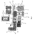
- An apparatus for processing glass green sheets 15 has according to Fig. 1 e.g. Glass bearing 1, 2, 4, as well as a portal feeder 3 for displacing the green glass panels 15, a laminated glass cutting apparatus 5, a cutting device 6 for float glass and a crushing device 7 therefor.
- the breaking device 7 consists of a so-called. X-crushing plant 7a and a so-called. Y-crushing plant 7b. Furthermore, it comprises a single cutting station 8 and an additional glass bearing 9.
- a device for example, a predetermined type of glass the Removed bearing 1, moved with the portal feeder 3 and placed on the processing table 11 and then in the Cutting system is driven.
- the optimizer determines that for the required or determined Cutting pattern (Figure 2) glass blank sheets 15 are needed These glass raw sheets 15 of the first type of glass from the feeder 3 the glass bearings 1, 2, 4 removed and on the processing table 11 launched. Subsequently, the cutting takes place in the cutting device 6 and breaking in the breaking device 7. Of the last glass panel 15, however, only one Part cut, the remaining part remains as a remainder glass panel 16 ( Figure 2).
- This residual glass panel 16 is in a rest store method. Subsequently, for example, follows a second other Glass variety (Fig. 2, middle row), in the same Is proceeded way. Thereafter, for example, again processed first type of glass, the process being the same as with the first type of glass, and again a remainder glass 16 remains.
- Fig. 3 also becomes a cutting pattern optimized to be cut glass rough sheets out, wherein after cutting the first type of glass (Fig. 3, top row) in the first run also a residual glass panel 16 remains.
- This residual glass panel 16 comes in the intermediate storage device according to the invention 20 (Fig. 4).
- the second Cut glass type whereby also in this run a ' Remaining glass panel 16 remains, which also in the intermediate storage device 20 is spent. Thereafter, for example again a run of the first type of glass.
- Residual glass panel 16 is the previously incurred in the first run of the first type of glass Residual glass panel 16 in the calculation of the cutting optimization introduced and preferably equal to the first glass plate with a determined by a computer cutting pattern in the Inserted cutting unit, scratched there and then in the Breaking device 7 decomposed into the individual slices.
- Residual glass panel 16 from the intermediate storage 20 in the cutting device 6 is introduced close normal glass panels with, possibly a rest accumulating likewise can be taken in the buffer 20.
- FIG. 4 A device according to the invention, shown in FIG. 4, for this purpose between the cutting device 6 and the breaking device 7, the latching device 20 on.
- the buffer device 20 has at least one bearing device 21 above the cutter 6 and a feeder 22 between the cutting device 6 and Breaking device 7 on.
- the storage device 21 has provided with rollers horizontally stacked Drawers 29 which are formed by their length and width forth are that a complete glass panel 15 or residual glass panel 16 is inserted.
- the axes of preferably in juxtaposed rows provided rollers in the Drawers 29 are oriented to be vertical to the insertion direction, d. H. horizontally in the transverse direction to the insertion direction.
- the top of the drawers 29 form the rollers on which the glass panels 15 or Restglastafeln 16 horizontally displaceable rest and on can roll the roles.
- Drawers 29 are the rows of rollers for supporting the glass panels preferably arranged laterally offset, so that one above the other lying rolls do not touch each other; in this way results in a low overall height of the drawers and thus the Storage device 21 for the same number of drawers 29.
- Die Height of the drawers 29 is slightly larger than the glassware sort with the greatest thickness, which in the intermediate storage device is to insert.
- the storage device 21 can therefore both for glass panels 15 and for residual glass panels 16 be used.
- the number of slots 29 is arbitrary, it depends on the size and utilization of the Plant and according to the height, which is available.
- the loading device 22 is in the working direction of the cutting system arranged downstream of the storage device and has a receiving table 23 for residual glass panels 16 or glass raw sheets 15, which is vertically movable.
- This receiving table 23 is preferably with non-driven rollers 25 and at least a gripper 26 equipped.
- the rollers are in the longitudinal direction cutting unit 36 at the top of several parallel, attached to each other spaced Kragarmen 23a attached.
- the cantilevers are vertically horizontal to a cross member 22a fixed, which is horizontal transversely to the direction of work extends and is guided on vertical support columns.
- This Gripper 26 is driven and destined to the residual glass panels 16 or glass panel 15 from the drawers 29 of the Storage device 21 to pull out on the table 23 or in to insert the drawers 29, this generally is flush with the loading and unloading side of the storage device 21, to facilitate the loading and unloading with the gripper 26.
- grippers 26 can also driven Rollers or a conveyor belt as a sliding device be used. With sufficient distance of the drawers 29th The device 21 can do this with pneumatic suckers or something similar happened.
- the conveyor exists preferably from single, arranged on the side gap Conveyor belts or in the longitudinal direction of the cutting system 36th arranged, parallel and driven conveyor roller rows. Stay between the conveyor belts or rows of conveyor rollers so that there are free spaces across the working direction. In addition are the conveyor belts or rows of conveyor rollers by a Free space 37 interrupted in the transverse direction of the cutting unit 36.
- the cross member 22 a of the charging device 22 can by the space 37 and the cantilevers of the receiving table 23 through the free spaces across the working direction between the conveyor belts or lower rows of conveyor rollers. In order to is the immersion of the shooting table 23 below the level of Glass plate on the conveyor possible.
- the lifting device 27 is constructed analogously, preferably a cross member and thus a free space in the transverse direction of the cutting system 36 is not required, because only a small difference in stroke between the top and bottom position is necessary, what a support column 38 is missing.
- the lifting movement is e.g. With Pneumatic cylinder devices below the level of the conveyor causes.
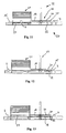
- FIGS. 5 to 10 show a method sequence of a method according to the invention Device with a simple shooting table in Side view shown schematically, with in Fig. 5 with the gripper 26 (not shown) a residual glass panel 16 from a Drawer 29 of the storage device 21 on the table 23 of the feeder 22 is pulled.
- the table 23 with the Residual glass panel 16 is then (Fig. 6) to above the Transport level of the cutting device 6 to the corresponding high-lift device 27 pushed (Fig. 7).
- the lifting device 27 (FIG. 8) is lowered and while the residual glass panel 16 on the conveyor of the Placed cutting table, the lifting device 27 under the level of the conveyor moves. After cutting (Fig.
- an intermediate storage device 20 is provided from a loading device 22 with a double support table 30 and a bearing device 21 shown in the basic position.
- the double support table 30 has an upper Shooting table 31 and a lower receiving table 32, which are arranged horizontally and vertically one above the other.
- the shooting tables 31, 32 are each with grippers 26, for example and rollers 25 as shown in FIG. 4 equipped.
- the broken pieces are removed the glass panel 15 in the working direction of the breaking device 7 (e.g., from the X crushing plant to the Y crushing plant).
- the residual glass panel 16 is returned to the breaking device 7 transported above the submerged lower receiving table 32 and the lifting device 27 is raised.
- the gripper 26 pushes one on the upper receiving table 31 located residual glass panel 16 on the lifting device 27.
- the sliding of the residual glass panel 16 the lifting device 27 and the transport of the residual glass panel 16 in the area between the two receiving tables 31, 32 on the conveyor as well as breaking happen at the same time.
- the lifting device 27 is lowered, so that the residual glass panel 16 on the cutting device. 6 rests and can be cut.
- the Tables 31, 32 of the feeder 22 moved up become.
- the located on the lower receiving table 32 Residual glass panel 16 can by means of the gripper 26 in a drawer 29 of the storage device 21 are inserted.
- the loading system 22 is at a corresponding height method and by means of the gripper 26 on the upper receiving table 31 from another drawer 29 a stored there Glass raw board 15 or remnant glass board 16 pulled.
- the charging device 22 with a double-table system 30 achieved a shorter cycle time, because the glass panel 15 or Residual glass panel 16 should not be transported to Eckübergabe got to.
- the distance of the receiving tables 31, 32nd immutable, so only one drive required is; but it may also be appropriate to separate the tables to arrange movable from each other.
- the two shooting tables with individual To drive motors so that these independently can be moved.
- the cycle time can be even further be shortened because - see Fig. 15 - the insertion of the Residual glass panel 16 or glass panel 15 and the withdrawal of the Glasrohtafel 15 or remainder glass panel 16 from an overlying Drawer 29 can be done simultaneously.
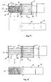
- Fig. 17 is a cutting device 6 and a breaking device 7 with a conveyor 34 and a storage facility 21 shown.
- the feeder 22 not disposed within the cutting crushing plant, but in front of the cutting device 6.
- the loading device 22 consists of four support columns 38, of which in the Side view of two support columns 38 are visible.
- the Shooting table 23 is used by the parallel in a plane at Cross beams 22a attached cantilevers formed 23a, here because of the side view only one cantilever 23a is visible.
- the two cross members 22a are in Fig. 17 perpendicular to the plane. This is only the attachment of the cross member 22a the column 38 visible.
- the two cross members 22a are at the Pillars 38 mounted vertically adjustable, so that the cantilever arms 23a and the recording table 23 formed by them in the Height is changeable.
- the feed with glass panels 15, takes place with the help of the movable Ablegekippticians 35, which vertically mounted glass raw sheets 15 from a warehouse receives, pivoted by 90 ° in the horizontal position and forward transported the conveyor belt 34 for receiving (not shown).
- the Auflegekipptisch 35 is for moving on the Floor preferably driven either by a conveyor belt or provided with rollers.
- the glass raw plate 15 with the conveyor belt 34 after cutting to the breaking device 7, shown in Fig. 18.
- the movable Auflegekipptisch 35 from the area below the charging device 22nd removed and the receiving table 23 at the height of the conveyor belt 34 lowered.
- Fig. 19 shows the transport of the residual glass panel 16 on the receiving table 23 with the gripper 26.
- the residual glass panel 16 after lifting the receiving table 23 with the Gripper 26 is inserted into a drawer 29 of the storage device 21.
- the transport of a glass raw board 15 or remainder glass board 16 takes place from the storage device 21 on the conveyor belt 34 in the reverse order as in FIG. 19 and FIG. 20 shown.
- the receiving table 23 after moving out of the laying tip table 35 shut down and then the Residual glass panel 16 on the receiving table 23 for insertion into the storage device 21 are moved.
- Fig. 21 and Fig. 22 are the plan view of a laminated glass cutting machine 5 with the crushing device 7 and a float glass cutting machine 33, both of which are movable Auflegekipptisch 35 according to FIG. 17 fed become.
- the charging device 22 is in front of the conveyor belt 34 of the laminated glass cutting 5 arranged.
- the loading device 22 has four vertical support columns 38, where two horizontal cross member 22a of a motor are mounted vertically displaceable.
- the cantilevers 23a fixed, which the Shooting table 23 form.
- the receiving table 23 means the height-displaceable mounting of the cross member 22a the columns 38 are adjusted in height.
- the bearing device 21 Due to the Transport between the laminated glass cutting 5 and the float glass cutting machine 33 may be the bearing device 21 also as a temporary storage for the float glass cutting system 33 be used.
- Laminated glass cutting 5 need, for example only about 16 glass panels 15 per working day.
- the storage device 21 can serve as a buffer memory and facilitate the loading of a main memory because out the main memory no withdrawals is necessary. For example is also a main memory maintenance during the Cutting process possible without downtime in production.
- Fig. 23 and Fig. 24 is a plan view of two cutting machines 36, e.g. a laminated glass cutting machine 5 or float glass cutting machine 33, shown, analogous to FIG. 21 and FIG. 22.
- a second storage device 21 arranged so that thus the buffer capacity is doubled.
- the advantage of the arrangement of the charging device 22 in front of the cutting unit 36 is under Another is that the conveyor belt 34 in the cutting system 36th must not be interrupted, because a dipping the shooting table 23 with a cross member in the conveyor of the Cutting system 36 is not necessary.
- the position of one or several storage facilities 21 in a cutting system with one or more cutting units 36 is arbitrary, because a Intermediate transport, for example with a movable support tilting table 35 or a portal feeder 3 is possible.
- the glass panels in particular Restglastafeln, not as before at the end of the conveyor line manually or mechanically must be extended and must be stored in an extra warehouse, but the glass plates after cutting in the crushing device in the appropriate Glass panes are cut, with the incurred Glass panel, in particular residual glass panel, is conveyed back in the direction of the cutting system and here on the processing table the displacement device arrives.
- the moving device raises the glass or residual glass panel on and off the conveyor plane, for example, between cutting and breaking device at a Float glass cutting machine, out to the height of one free insertion compartment of the storage facility.
Claims (42)
- Procédé de façonnage de panneaux en verre, dans lequel des modèles de coupe sont répartis, par voie de calcul de façon optimisée en termes de surface, sur des surfaces de panneaux en verre bruts et, ensuite, une quantité correspondante de panneaux en verre bruts (15) est acheminée vers un dispositif de coupe (36) et découpée conformément au modèle calculé, puis rompue, moyennant quoi il subsiste des panneaux en verre résiduels (16), caractérisé en ce que les panneaux en verre résiduels (16) sont placés dans une unité de dépôt temporaire (20), et y sont stockés horizontalement, leurs dimensions, leur nombre et leur lieu de stockage faisant l'objet d'un enregistrement assisté par ordinateur, et les panneaux en verre résiduels (16) stockés dans l'unité de dépôt temporaire (20) sont pris en compte lors du calcul de modèle de coupe suivant, sélectionnés et acheminés vers le dispositif de coupe (36).
- Procédé selon la revendication 1, caractérisé en ce que les panneaux en verre résiduels (16) sont acheminés vers le dispositif de coupe (36), en qualité de premiers panneaux d'un type de panneaux en verre (15, 16) associé au modèle de coupe, devant être découpé.
- Procédé selon la revendication 1 ou 2, caractérisé en ce que les panneaux en verre résiduels (16) sont soulevés verticalement en partant d'un niveau de ligne de coupe, introduits horizontalement dans un dispositif de stockage (21) et placés au niveau de la ligne de coupe de manière à être utilisés dans l'ordre inverse.
- Procédé selon une ou plusieurs des revendications 1 à 3, caractérisé en ce que les panneaux en verre bruts (15) sont introduits dans l'unité de dépôt temporaire (20) et y sont stockés horizontalement, leurs dimensions, leur nombre et leur lieu de stockage faisant l'objet d'un enregistrement assisté par ordinateur, et les panneaux en verre bruts (15) stockés dans l'unité de dépôt temporaire (20) sont pris en compte lors d'un calcul de modèle suivant, sélectionnés et acheminés vers le dispositif de coupe (36).
- Procédé selon une des revendications 1 à 4, caractérisé en ce que les panneaux en verre résiduels (16) ou panneaux en verre bruts (15) sont acheminés vers le dispositif de coupe (36) à un moment quelconque.
- Procédé selon une ou plusieurs des revendications 1 à 5, caractérisé en ce que, pour les panneaux en verre résiduels (16), on établit un modèle de coupe optimisé en termes de surface, et les panneaux en verre résiduels (16) sont subdivisés en conséquence.
- Procédé selon la revendication 6, caractérisé en ce que le modèle de coupe des panneaux en verre résiduels (16) est combiné au modèle de coupe des panneaux en verre bruts (15).
- Procédé selon une des revendications 1 à 7, caractérisé en ce que les panneaux en verre résiduels (16) reviennent, à l'aide d'un moyen de transport, de la ligne de coupe jusqu'à un dispositif de chargement (22).
- Procédé selon une ou plusieurs des revendications précédentes, caractérisé en ce que les panneaux en verre résiduels (16) sont rangés dans la ligne de panneaux en verre bruts correspondant au modèle de coupe.
- Procédé selon une ou plusieurs des revendications précédentes, caractérisé en ce que les panneaux en verre bruts (15) sont rangés dans la ligne des panneaux en verre bruts correspondant au modèle de coupe.
- Procédé de façonnage de panneaux en verre, dans lequel des modèles de coupe sont répartis, par voie de calcul de façon optimisée en termes de surface, sur les surfaces des panneaux en verre bruts et, ensuite, une quantité correspondante de panneaux en verre bruts (15) est acheminée vers un dispositif de coupe (36) et découpée conformément au modèle calculé, puis rompue, moyennant quoi il peut subsister des panneaux en verre résiduels (16), caractérisé en ce que les panneaux en verre bruts (15) sont placés dans une unité de dépôt temporaire (20) et y sont stockés horizontalement, leurs dimensions, leur nombre et leur lieu de stockage faisant l'objet d'un enregistrement assisté par ordinateur, et les panneaux en verre bruts (15) stockés dans l'unité de dépôt temporaire (20) sont pris en compte lors d'un calcul de modèle de coupe suivant, sélectionnés et acheminés vers le dispositif de coupe (36).
- Procédé selon la revendication 11, caractérisé en ce que les panneaux en verre bruts (15) sont rangés dans la ligne de panneaux en verre bruts correspondant au modèle de coupe.
- Procédé selon une ou plusieurs des revendications précédentes, caractérisé en ce que le stockage des panneaux en verre résiduels (16) et/ou des panneaux en verre bruts (15) dans l'unité de dépôt temporaire (20) s'effectue au-dessus de la ligne de coupe.
- Procédé selon une ou plusieurs des revendications précédentes, caractérisé en ce que les panneaux en verre résiduels (16) et/ou les panneaux en verre bruts (15) sont stockés horizontalement les uns au-dessus des autres.
- Dispositif de façonnage de panneaux en verre, en particulier pour la mise en oeuvre du procédé selon une des revendications 1 à 14, qui comprend de préférence au moins un dispositif de stockage (1, 2, 4) pour les panneaux en verre bruts (15) non façonnés, au moins un dispositif de transfert (3) destiné à extraire les panneaux en verre bruts (15) des dispositifs de stockage (1, 2, 4), au moins un dispositif de coupe (35), par exemple une installation de coupe de verre composite (5) ou une installation de coupe de verre flottant (33) destinée à la découpe des panneaux en verre bruts transportés au moyen du dispositif de transfert (3), et de préférence au moins un dispositif de fragmentation (7) destiné à diviser les panneaux en verre bruts (15) en vitres, et éventuellement au moins un dispositif de tri destiné à loger et trier les panneaux en verre découpés, caractérisé en ce qu'il est prévu un dispositif de dépôt temporaire (20) dans lequel les panneaux en verre résiduels (16) et/ou les panneaux en verre bruts ( 15) peuvent être stockés horizontalement.
- Dispositif selon la revendication 15, caractérisé en ce que le dispositif de dépôt temporaire (20) est disposé au-dessus de la ligne de coupe.
- Dispositif selon la revendication 15 et/ou la revendication 16, caractérisé en ce que, dans le dispositif de dépôt temporaire (20), les panneaux en verre résiduels (16) et/ou les panneaux en verre bruts (15) sont stockés en étant disposés horizontalement les uns au-dessus des autres.
- Dispositif selon une ou plusieurs des revendications 15 à 17, caractérisé en ce que le dispositif de dépôt temporaire (20) présente au moins un dispositif de stockage (21) dans lequel les panneaux en verre résiduels (16) et/ou les panneaux en verre bruts (15) peuvent être logés.
- Dispositif selon une ou plusieurs des revendications 15 à 18, caractérisé en ce que le dispositif de stockage (21) présente des tiroirs coulissants (29) dans lesquels reposent les panneaux en verre bruts (15) ou les panneaux en verre résiduels (16).
- Dispositif selon la revendication 19, caractérisé en ce que la hauteur des tiroirs coulissants (20) est légèrement supérieure à celle du type de panneaux en verre présentant la plus grande épaisseur, qui doivent être introduits dans le dispositif de stockage (21).
- Dispositif selon la revendication 19 et/ou 20, caractérisé en ce que les panneaux en verre bruts (15) ou panneaux en verre résiduels (16) reposent sur la face supérieure des tiroirs coulissants (29) sur des rouleaux (25) dont les axes sont situés horizontalement dans la direction transversale du dispositif de stockage (21).
- Dispositif selon la revendication 21, caractérisé en ce que les rouleaux (25), disposés les uns au-dessus des autres dans les tiroirs coulissants (29) du dispositif de stockage (21), sont de préférence décalés.
- Dispositif selon une des revendications 15 à 22, caractérisé en ce qu'il est prévu un dispositif de chargement (22) qui prélève les panneaux en verre résiduels (16) de l'installation de fragmentation (7), et les transfère vers le dispositif de stockage (21).
- Dispositif selon la revendication 23, caractérisé en ce que le dispositif de chargement (22) prélève les panneaux en verre résiduels (16) ou les panneaux en verre bruts (15) du dispositif de coupe (36) et les transfère vers le dispositif de stockage (21), de préférence à fleur du côté de chargement et du côté de prélèvement.
- Dispositif selon la revendication 23 et/ou 24, caractérisé en ce que le dispositif de chargement (22) présente une table de pose (23) sur laquelle reposent les panneaux en verre résiduels (16) et/ou les panneaux en verre bruts (15).
- Dispositif selon la revendication 25, caractérisé en ce que les panneaux en verre résiduels (16) et/ou les panneaux en verre bruts (15) reposent sur le dispositif de pose (23) sur des rouleaux (25).
- Dispositif selon une des revendications 23 à 26, caractérisé en ce que le dispositif de chargement (22) est disposé entre deux dispositifs de stockage (21), le premier dispositif de stockage (21) étant disposé au-dessus du dispositif de coupe (36) et l'autre dispositif de stockage (21) au-dessus du dispositif de fragmentation (7).
- Dispositif selon une des revendications 15 à 27, caractérisé en ce que, au-dessous du dispositif de stockage, (21) est prévu un dispositif élévateur (27) sur lequel les panneaux en verre résiduels (16) peuvent être posés depuis le dispositif de chargement (22) et être transmis au dispositif de coupe (36).
- Dispositif selon une ou plusieurs des revendications 23 à 28, caractérisé en ce que le dispositif de chargement (22) présente une table de réception supérieure (31) et une table de réception inférieure (32).
- Dispositif selon une ou plusieurs des revendications 23 à 29, caractérisé en ce que le dispositif de chargement (22) présente au moins trois tables de réception (23).
- Dispositif selon une des revendications 25 à 30, caractérisé en ce que les tables de réception (23, 31, 32) sont entraínées individuellement ou conjointement.
- Dispositif selon une des revendications 25 à 31, caractérisé en ce que, sur les tables de réception (23, 31, 32), des rouleaux non entraínés et une pince (26), des rouleaux entraínés ou au moins une bande transporteuse sont disposés sur des bras en porte-à-faux (23a) pour transporter les panneaux en verre bruts (15) et/ou les panneaux en verre résiduels (16), les bras en porte-à-faux (23a) étant fixés perpendiculairement à une poutre transversale (22a).
- Dispositif selon une des revendications 25 à 32, caractérisé en ce qu'au moins une table de réception (23, 31, 32) arrive en dessous du niveau de la face supérieure du dispositif de transport ou de la table de pose du dispositif de coupe (36).
- Dispositif selon la revendication 33, caractérisé en ce que le dispositif de transport de l'installation de coupe (36) est composé de bandes transporteuses ou de rouleaux transporteurs entraínés, disposés les uns à la suite des autres dans la direction longitudinale de l'installation de coupe (36), et qui présentent des espaces libres dans la direction longitudinale, et de préférence un espace libre (37) dans la direction transversale.
- Dispositif selon la revendication 34, caractérisé en ce que les bras en porte-à-faux (23a) des tables de réception (23, 31, 32) peuvent se déplacer entre les espaces libres dans la direction longitudinale du dispositif de transport, et de préférence dans un espace libre (37) dans la direction transversale des poutres transversales (22a) des tables de réception (23, 31, 32).
- Dispositif selon une des revendications 15 à 35, caractérisé en ce qu'au moins deux dispositifs de coupe (36) sont accouplés à un dispositif de transfert (3), de préférence sous la forme d'un chargeur à portique (3) ou d'une table basculante de pose mobile (35) les uns aux autres pour l'échange de panneaux en verre bruts (15) ou de panneaux en verre résiduels (16), de telle sorte qu'en particulier les dispositifs de dépôt temporaire (20) sont disponibles pour chacun des dispositifs de coupe accouplés (6).
- Dispositif selon une des revendications 23 à 36, caractérisé en ce que le dispositif de chargement (22) est disposé entre deux dispositifs de stockage (21), le premier dispositif de stockage (21) étant disposé au-dessus du dispositif de coupe (36), et l'autre dispositif de stockage (21) au-dessus du dispositif de fragmentation (7).
- Dispositif selon une des revendications 18 à 37, caractérisé en ce que le dispositif de stockage (21) est positionné à un endroit quelconque, mais de préférence au-dessus de dispositif de coupe (36).
- Dispositif selon une des revendications 23 à 38, caractérisé en ce que le dispositif de chargement (22) est disposé en amont du dispositif de coupe (36).
- Dispositif selon une des revendications 23 à 39, caractérisé en ce qu'il est prévu au moins un dispositif élévateur (27) sur lequel les panneaux en verre résiduels (16) ou les panneaux en verre bruts (15) sont déposés en provenance du dispositif de chargement (22) et peuvent être transmis au dispositif de coupe (36).
- Dispositif selon la revendication 40, caractérisé en ce que le dispositif élévateur (27) arrive en dessous du niveau de la face supérieure du dispositif de transport du dispositif de coupe (36).
- Dispositif selon la revendication 40 et/ou 41, caractérisé en ce que la région de pose du dispositif élévateur (27) est composée de poutres longitudinales distinctes qui peuvent se déplacer dans les espaces libres du dispositif de transport, dans la direction longitudinale du dispositif de coupe (36).
Priority Applications (1)
| Application Number | Priority Date | Filing Date | Title |
|---|---|---|---|
| DE20220733U DE20220733U1 (de) | 2001-08-13 | 2002-08-13 | Vorrichtung zum Bearbeiten von Glastafeln |
Applications Claiming Priority (2)
| Application Number | Priority Date | Filing Date | Title |
|---|---|---|---|
| DE10139715 | 2001-08-13 | ||
| DE10139715A DE10139715B4 (de) | 2001-08-13 | 2001-08-13 | Verfahren und Vorrichtung zum Bearbeiten von Glastafeln |
Publications (5)
| Publication Number | Publication Date |
|---|---|
| EP1284229A2 EP1284229A2 (fr) | 2003-02-19 |
| EP1284229A3 EP1284229A3 (fr) | 2004-04-14 |
| EP1284229B1 true EP1284229B1 (fr) | 2005-04-27 |
| EP1284229B8 EP1284229B8 (fr) | 2005-06-29 |
| EP1284229B3 EP1284229B3 (fr) | 2012-12-12 |
Family
ID=7695297
Family Applications (1)
| Application Number | Title | Priority Date | Filing Date |
|---|---|---|---|
| EP02018069A Expired - Lifetime EP1284229B3 (fr) | 2001-08-13 | 2002-08-13 | Procédé et appareil de manipulation des feuilles de verre |
Country Status (3)
| Country | Link |
|---|---|
| EP (1) | EP1284229B3 (fr) |
| AT (1) | ATE294122T1 (fr) |
| DE (2) | DE10139715B4 (fr) |
Cited By (1)
| Publication number | Priority date | Publication date | Assignee | Title |
|---|---|---|---|---|
| DE202010017191U1 (de) | 2010-09-23 | 2011-04-14 | Hegla Gmbh & Co. Kg | Zwischenspeichervorrichtung für Restglastafeln |
Families Citing this family (9)
| Publication number | Priority date | Publication date | Assignee | Title |
|---|---|---|---|---|
| DE20216438U1 (de) * | 2002-10-24 | 2004-03-04 | Lisec, Peter | Glasschneideanlage mit Zwischenspeicher |
| CA2460859A1 (fr) | 2003-03-13 | 2004-09-13 | Bromer Inc. | Systeme de stockage des chutes de verre |
| CA2421121A1 (fr) | 2003-03-13 | 2004-09-13 | Roger Mercure | Dispositif et methode pour la valorisation et l'optimisation de panneaux a decouper |
| ATE537126T1 (de) * | 2006-08-17 | 2011-12-15 | Albat & Wirsam Software Ag | Verfahren und vorrichtung zum zuschneiden von rohglasplatten |
| EP2156914A1 (fr) | 2008-08-19 | 2010-02-24 | Arnout De Lille | Système de contrôle et son procédé de découpage |
| AT509220B1 (de) | 2010-06-07 | 2011-07-15 | Hermann Sonnleitner | Manipulationsvorrichtung für ein flachglaslager |
| ITTO20110370A1 (it) * | 2011-04-28 | 2012-10-29 | Biesse Spa | Macchina e procedimento per il taglio di una lastra di vetro stratificato |
| ITTO20120903A1 (it) | 2012-10-16 | 2014-04-17 | Biesse Spa | Macchina per eseguire il taglio di una lastra di vetro stratificato con una sezione di attesa dotata di mezzi di trasporto |
| ES2671567T3 (es) * | 2014-09-11 | 2018-06-07 | Bottero S.P.A. | Método y máquina para cortar una hoja de vidrio |
Family Cites Families (7)
| Publication number | Priority date | Publication date | Assignee | Title |
|---|---|---|---|---|
| LU52576A1 (fr) * | 1966-12-13 | 1968-08-16 | ||
| EP0048334B1 (fr) | 1980-09-24 | 1984-03-07 | Bystronic Maschinen AG | Appareil pour le triage de feuilles de verre non triées d'une installation de coupe de verre |
| FI86834C (fi) * | 1988-05-11 | 1992-10-26 | Tamglass Eng Oy | Mellanlagringssystem foer glasskivpar i en vindruteproduktionslinje |
| DE19600348C2 (de) * | 1996-01-08 | 2001-11-22 | Lewecke Maschb Gmbh | Regalanlage für Platten |
| JP4496447B2 (ja) * | 2000-07-06 | 2010-07-07 | 株式会社Ihi | 基板移載装置 |
| DE10161813A1 (de) * | 2001-12-14 | 2003-06-26 | Albat & Wirsam Software Vertri | Verfahren und Vorrichtung zum Teilen von Glasplatten in Zuschnitte |
| DE10164071A1 (de) * | 2001-12-24 | 2003-07-03 | Hegla Fahrzeug Und Maschb Gmbh | Verfahren und Vorrichtung zum Sortieren von Glastafeln |
-
2001
- 2001-08-13 DE DE10139715A patent/DE10139715B4/de not_active Expired - Fee Related
-
2002
- 2002-08-13 AT AT02018069T patent/ATE294122T1/de active
- 2002-08-13 DE DE50202889T patent/DE50202889D1/de not_active Expired - Lifetime
- 2002-08-13 EP EP02018069A patent/EP1284229B3/fr not_active Expired - Lifetime
Cited By (5)
| Publication number | Priority date | Publication date | Assignee | Title |
|---|---|---|---|---|
| DE202010017191U1 (de) | 2010-09-23 | 2011-04-14 | Hegla Gmbh & Co. Kg | Zwischenspeichervorrichtung für Restglastafeln |
| EP2433886A2 (fr) | 2010-09-23 | 2012-03-28 | HEGLA GmbH & Co. KG | Procédé de fonctionnement d'un accumulateur temporaire pour piles de verre résiduel et dispositif d'accumulation temporaire pour piles de verre résiduel |
| DE102010046330A1 (de) | 2010-09-23 | 2012-03-29 | Hegla Gmbh & Co. Kg | Verfahren zum Betreiben eines Zwischenspeichers für Restglastafeln sowie Zwischenspeichervorrichtung für Restglastafeln |
| EP2433886A3 (fr) * | 2010-09-23 | 2012-06-06 | HEGLA GmbH & Co. KG | Procédé de fonctionnement d'un accumulateur temporaire pour piles de verre résiduel et dispositif d'accumulation temporaire pour piles de verre résiduel |
| DE102010046330B4 (de) | 2010-09-23 | 2018-03-29 | Hegla Gmbh & Co. Kg | Verfahren zum Betreiben eines Zwischenspeichers für Restglastafeln sowie Zwischenspeichervorrichtung für Restglastafeln |
Also Published As
| Publication number | Publication date |
|---|---|
| DE50202889D1 (de) | 2005-06-02 |
| EP1284229A3 (fr) | 2004-04-14 |
| EP1284229B3 (fr) | 2012-12-12 |
| EP1284229B8 (fr) | 2005-06-29 |
| DE10139715B4 (de) | 2005-02-03 |
| DE10139715A1 (de) | 2003-02-27 |
| EP1284229A2 (fr) | 2003-02-19 |
| ATE294122T1 (de) | 2005-05-15 |
Similar Documents
| Publication | Publication Date | Title |
|---|---|---|
| EP1572558B2 (fr) | Poste de preparation de commandes et methode | |
| EP1319634B1 (fr) | Procédé et appareil de découpe des feuilles de verre en plaques individuelles | |
| DE2702725C2 (de) | Plattenaufteil-, sortier- und -stapelanlage mit mindestens einer Stapeleinrichtung | |
| EP2050523B1 (fr) | Agencement mécanique pour le traitement de tôle à l'aide d'un dispositif de traitement de tôle ainsi que dispositif de transport | |
| EP0241824A2 (fr) | Installation de transfert de marchandises et procédé permettant son opération | |
| CH659419A5 (de) | Handhabungseinrichtung fuer werkstuecke. | |
| EP0564758B1 (fr) | Procédé et appareil pour diviser des plaques en verre en parties | |
| EP1284229B1 (fr) | Procédé et appareil de manipulation des feuilles de verre | |
| EP1323651B1 (fr) | Procédé et appareil pour trier des feuilles de verre | |
| EP0816265B1 (fr) | Dispositif pour ranger des feuilles de verre coupées | |
| AT390026B (de) | Vorrichtung zum buntaufteilen von plattenfoermigen werkstuecken | |
| DE3326200A1 (de) | Regallager zur lagerung von stangenfoermigem material | |
| DE102018214131B4 (de) | Shuttle zum Verfahren von Glastafeln und Speichervorrichtung mit zumindest einem derartigen Shuttle | |
| DE20220733U1 (de) | Vorrichtung zum Bearbeiten von Glastafeln | |
| EP0907589B1 (fr) | Systeme d'emmagasinage pour produits sous forme de plaques | |
| EP3733560A1 (fr) | Entrepôt de plaques | |
| DE3439969A1 (de) | Verfahren und vorrichtung zum vereinzeln von waerm- oder walzgut | |
| DE102021125391B4 (de) | Entstapelungsvorrichtung und Holzbearbeitungsanlage mit einer derartigen Entstapelungsvorrichtung | |
| EP0206992B1 (fr) | Installation de stockage | |
| AT398745B (de) | Einrichtung zum sortieren von unterschiedlichen, auf buntaufteilanlagen aus plattenförmigen werkstücken durch längs- und querschnitte gewonnene formatzuschnitte | |
| AT509220B1 (de) | Manipulationsvorrichtung für ein flachglaslager | |
| DE3436764C1 (de) | Vorrichtung zum Sortieren von Tafeln | |
| DE602005002074T2 (de) | Verfahren und Vorrichtung für die Handhabung und Wiedereinsetzung der Ladenmaßeinheiten wie Kästen, Postbehälter oder dergleichen | |
| DE4137169A1 (de) | Foerdereinrichtung fuer stangenmaterial | |
| EP1275600A1 (fr) | Dispositif pour alimenter une unité de traitement en articles, notamment à une imprimeuse |
Legal Events
| Date | Code | Title | Description |
|---|---|---|---|
| PUAI | Public reference made under article 153(3) epc to a published international application that has entered the european phase |
Free format text: ORIGINAL CODE: 0009012 |
|
| AK | Designated contracting states |
Designated state(s): AT BE BG CH CY CZ DE DK EE ES FI FR GB GR IE IT LI LU MC NL PT SE SK TR |
|
| AX | Request for extension of the european patent |
Extension state: AL LT LV MK RO SI |
|
| PUAL | Search report despatched |
Free format text: ORIGINAL CODE: 0009013 |
|
| AK | Designated contracting states |
Kind code of ref document: A3 Designated state(s): AT BE BG CH CY CZ DE DK EE ES FI FR GB GR IE IT LI LU MC NL PT SE SK TR |
|
| AX | Request for extension of the european patent |
Extension state: AL LT LV MK RO SI |
|
| 17P | Request for examination filed |
Effective date: 20040329 |
|
| 17Q | First examination report despatched |
Effective date: 20040525 |
|
| GRAP | Despatch of communication of intention to grant a patent |
Free format text: ORIGINAL CODE: EPIDOSNIGR1 |
|
| AKX | Designation fees paid |
Designated state(s): AT BE BG CH CY CZ DE DK EE ES FI FR GB GR IE IT LI LU MC NL PT SE SK TR |
|
| GRAS | Grant fee paid |
Free format text: ORIGINAL CODE: EPIDOSNIGR3 |
|
| GRAA | (expected) grant |
Free format text: ORIGINAL CODE: 0009210 |
|
| AK | Designated contracting states |
Kind code of ref document: B1 Designated state(s): AT BE BG CH CY CZ DE DK EE ES FI FR GB GR IE IT LI LU MC NL PT SE SK TR |
|
| PG25 | Lapsed in a contracting state [announced via postgrant information from national office to epo] |
Ref country code: TR Free format text: LAPSE BECAUSE OF FAILURE TO SUBMIT A TRANSLATION OF THE DESCRIPTION OR TO PAY THE FEE WITHIN THE PRESCRIBED TIME-LIMIT Effective date: 20050427 Ref country code: NL Free format text: LAPSE BECAUSE OF FAILURE TO SUBMIT A TRANSLATION OF THE DESCRIPTION OR TO PAY THE FEE WITHIN THE PRESCRIBED TIME-LIMIT Effective date: 20050427 Ref country code: IE Free format text: LAPSE BECAUSE OF FAILURE TO SUBMIT A TRANSLATION OF THE DESCRIPTION OR TO PAY THE FEE WITHIN THE PRESCRIBED TIME-LIMIT Effective date: 20050427 Ref country code: CZ Free format text: LAPSE BECAUSE OF FAILURE TO SUBMIT A TRANSLATION OF THE DESCRIPTION OR TO PAY THE FEE WITHIN THE PRESCRIBED TIME-LIMIT Effective date: 20050427 Ref country code: FI Free format text: LAPSE BECAUSE OF FAILURE TO SUBMIT A TRANSLATION OF THE DESCRIPTION OR TO PAY THE FEE WITHIN THE PRESCRIBED TIME-LIMIT Effective date: 20050427 Ref country code: SK Free format text: LAPSE BECAUSE OF FAILURE TO SUBMIT A TRANSLATION OF THE DESCRIPTION OR TO PAY THE FEE WITHIN THE PRESCRIBED TIME-LIMIT Effective date: 20050427 Ref country code: EE Free format text: LAPSE BECAUSE OF FAILURE TO SUBMIT A TRANSLATION OF THE DESCRIPTION OR TO PAY THE FEE WITHIN THE PRESCRIBED TIME-LIMIT Effective date: 20050427 |
|
| REG | Reference to a national code |
Ref country code: GB Ref legal event code: FG4D Free format text: NOT ENGLISH |
|
| REG | Reference to a national code |
Ref country code: CH Ref legal event code: EP |
|
| REG | Reference to a national code |
Ref country code: IE Ref legal event code: FG4D Free format text: LANGUAGE OF EP DOCUMENT: GERMAN |
|
| REF | Corresponds to: |
Ref document number: 50202889 Country of ref document: DE Date of ref document: 20050602 Kind code of ref document: P |
|
| RAP2 | Party data changed (patent owner data changed or rights of a patent transferred) |
Owner name: HEGLA GMBH & CO. KG |
|
| REG | Reference to a national code |
Ref country code: CH Ref legal event code: NV Representative=s name: BRAUNPAT BRAUN EDER AG |
|
| PG25 | Lapsed in a contracting state [announced via postgrant information from national office to epo] |
Ref country code: GR Free format text: LAPSE BECAUSE OF FAILURE TO SUBMIT A TRANSLATION OF THE DESCRIPTION OR TO PAY THE FEE WITHIN THE PRESCRIBED TIME-LIMIT Effective date: 20050727 Ref country code: DK Free format text: LAPSE BECAUSE OF FAILURE TO SUBMIT A TRANSLATION OF THE DESCRIPTION OR TO PAY THE FEE WITHIN THE PRESCRIBED TIME-LIMIT Effective date: 20050727 Ref country code: SE Free format text: LAPSE BECAUSE OF FAILURE TO SUBMIT A TRANSLATION OF THE DESCRIPTION OR TO PAY THE FEE WITHIN THE PRESCRIBED TIME-LIMIT Effective date: 20050727 Ref country code: BG Free format text: LAPSE BECAUSE OF FAILURE TO SUBMIT A TRANSLATION OF THE DESCRIPTION OR TO PAY THE FEE WITHIN THE PRESCRIBED TIME-LIMIT Effective date: 20050727 |
|
| NLT2 | Nl: modifications (of names), taken from the european patent patent bulletin |
Owner name: HEGLA GMBH & CO. KG |
|
| PG25 | Lapsed in a contracting state [announced via postgrant information from national office to epo] |
Ref country code: ES Free format text: LAPSE BECAUSE OF FAILURE TO SUBMIT A TRANSLATION OF THE DESCRIPTION OR TO PAY THE FEE WITHIN THE PRESCRIBED TIME-LIMIT Effective date: 20050807 |
|
| PG25 | Lapsed in a contracting state [announced via postgrant information from national office to epo] |
Ref country code: CY Free format text: LAPSE BECAUSE OF FAILURE TO SUBMIT A TRANSLATION OF THE DESCRIPTION OR TO PAY THE FEE WITHIN THE PRESCRIBED TIME-LIMIT Effective date: 20050813 Ref country code: LU Free format text: LAPSE BECAUSE OF NON-PAYMENT OF DUE FEES Effective date: 20050813 |
|
| PG25 | Lapsed in a contracting state [announced via postgrant information from national office to epo] |
Ref country code: MC Free format text: LAPSE BECAUSE OF NON-PAYMENT OF DUE FEES Effective date: 20050831 |
|
| PG25 | Lapsed in a contracting state [announced via postgrant information from national office to epo] |
Ref country code: PT Free format text: LAPSE BECAUSE OF FAILURE TO SUBMIT A TRANSLATION OF THE DESCRIPTION OR TO PAY THE FEE WITHIN THE PRESCRIBED TIME-LIMIT Effective date: 20051010 |
|
| GBT | Gb: translation of ep patent filed (gb section 77(6)(a)/1977) |
Effective date: 20050920 |
|
| NLV1 | Nl: lapsed or annulled due to failure to fulfill the requirements of art. 29p and 29m of the patents act | ||
| REG | Reference to a national code |
Ref country code: IE Ref legal event code: FD4D |
|
| PLBE | No opposition filed within time limit |
Free format text: ORIGINAL CODE: 0009261 |
|
| ET | Fr: translation filed | ||
| 26N | No opposition filed |
Effective date: 20060130 |
|
| REG | Reference to a national code |
Ref country code: DE Ref legal event code: R097 Ref document number: 50202889 Country of ref document: DE |
|
| REG | Reference to a national code |
Ref country code: DE Ref legal event code: R055 Ref document number: 50202889 Country of ref document: DE |
|
| PG25 | Lapsed in a contracting state [announced via postgrant information from national office to epo] |
Ref country code: IT Free format text: LAPSE BECAUSE OF NON-PAYMENT OF DUE FEES Effective date: 20100813 |
|
| PLCP | Request for limitation filed |
Free format text: ORIGINAL CODE: EPIDOSNLIM1 |
|
| PLCQ | Request for limitation of patent found admissible |
Free format text: ORIGINAL CODE: 0009231 |
|
| REG | Reference to a national code |
Ref country code: DE Ref legal event code: R040 Ref document number: 50202889 Country of ref document: DE Effective date: 20110217 |
|
| PGRI | Patent reinstated in contracting state [announced from national office to epo] |
Ref country code: IT Effective date: 20110616 |
|
| LIM1 | Request for limitation found admissible |
Free format text: SEQUENCE NO: 1; FILED AFTER OPPOSITION PERIOD Filing date: 20110421 |
|
| PLCE | Limitation procedure: information deleted related to despatch of communication from examining division + time limit |
Free format text: ORIGINAL CODE: EPIDOSDLIR2 |
|
| PLCR | Communication despatched that request for limitation of patent was allowed |
Free format text: ORIGINAL CODE: 0009245 |
|
| REG | Reference to a national code |
Ref country code: DE Ref legal event code: R097 Ref document number: 50202889 Country of ref document: DE |
|
| REG | Reference to a national code |
Ref country code: DE Ref legal event code: R056 Ref document number: 50202889 Country of ref document: DE Effective date: 20110812 |
|
| PLCN | Payment of fee for limitation of patent |
Free format text: ORIGINAL CODE: EPIDOSNRAL3 |
|
| PUAM | (expected) publication of b3 document |
Free format text: ORIGINAL CODE: 0009410 |
|
| STAA | Information on the status of an ep patent application or granted ep patent |
Free format text: STATUS: THE PATENT HAS BEEN LIMITED |
|
| REG | Reference to a national code |
Ref country code: CH Ref legal event code: AELM |
|
| PGFP | Annual fee paid to national office [announced via postgrant information from national office to epo] |
Ref country code: CH Payment date: 20130827 Year of fee payment: 12 |
|
| REG | Reference to a national code |
Ref country code: CH Ref legal event code: PL |
|
| PG25 | Lapsed in a contracting state [announced via postgrant information from national office to epo] |
Ref country code: CH Free format text: LAPSE BECAUSE OF NON-PAYMENT OF DUE FEES Effective date: 20140831 Ref country code: LI Free format text: LAPSE BECAUSE OF NON-PAYMENT OF DUE FEES Effective date: 20140831 |
|
| REG | Reference to a national code |
Ref country code: FR Ref legal event code: PLFP Year of fee payment: 15 |
|
| REG | Reference to a national code |
Ref country code: FR Ref legal event code: PLFP Year of fee payment: 16 |
|
| REG | Reference to a national code |
Ref country code: FR Ref legal event code: PLFP Year of fee payment: 17 |
|
| PGFP | Annual fee paid to national office [announced via postgrant information from national office to epo] |
Ref country code: FR Payment date: 20210708 Year of fee payment: 20 Ref country code: AT Payment date: 20210727 Year of fee payment: 20 Ref country code: IT Payment date: 20210708 Year of fee payment: 20 |
|
| PGFP | Annual fee paid to national office [announced via postgrant information from national office to epo] |
Ref country code: GB Payment date: 20210708 Year of fee payment: 20 Ref country code: BE Payment date: 20210706 Year of fee payment: 20 |
|
| PGFP | Annual fee paid to national office [announced via postgrant information from national office to epo] |
Ref country code: DE Payment date: 20211029 Year of fee payment: 20 |
|
| REG | Reference to a national code |
Ref country code: DE Ref legal event code: R071 Ref document number: 50202889 Country of ref document: DE |
|
| REG | Reference to a national code |
Ref country code: GB Ref legal event code: PE20 Expiry date: 20220812 |
|
| REG | Reference to a national code |
Ref country code: BE Ref legal event code: MK Effective date: 20220813 |
|
| REG | Reference to a national code |
Ref country code: AT Ref legal event code: MK07 Ref document number: 294122 Country of ref document: AT Kind code of ref document: T Effective date: 20220813 |
|
| PG25 | Lapsed in a contracting state [announced via postgrant information from national office to epo] |
Ref country code: GB Free format text: LAPSE BECAUSE OF EXPIRATION OF PROTECTION Effective date: 20220812 |