EP1284039B1 - Thermische überwachung eines elektrischen lastelementes - Google Patents
Thermische überwachung eines elektrischen lastelementes Download PDFInfo
- Publication number
- EP1284039B1 EP1284039B1 EP01942982A EP01942982A EP1284039B1 EP 1284039 B1 EP1284039 B1 EP 1284039B1 EP 01942982 A EP01942982 A EP 01942982A EP 01942982 A EP01942982 A EP 01942982A EP 1284039 B1 EP1284039 B1 EP 1284039B1
- Authority
- EP
- European Patent Office
- Prior art keywords
- load
- parameter
- time
- controller
- switching
- Prior art date
- Legal status (The legal status is an assumption and is not a legal conclusion. Google has not performed a legal analysis and makes no representation as to the accuracy of the status listed.)
- Expired - Lifetime
Links
- 238000012544 monitoring process Methods 0.000 title claims abstract description 25
- 238000000034 method Methods 0.000 claims abstract description 25
- 238000004364 calculation method Methods 0.000 claims description 16
- 230000015654 memory Effects 0.000 claims description 15
- 230000006870 function Effects 0.000 claims description 10
- 238000011156 evaluation Methods 0.000 claims description 5
- 238000003745 diagnosis Methods 0.000 claims description 2
- 238000013021 overheating Methods 0.000 claims description 2
- 238000001816 cooling Methods 0.000 description 29
- 238000010438 heat treatment Methods 0.000 description 23
- 238000009529 body temperature measurement Methods 0.000 description 22
- 230000006399 behavior Effects 0.000 description 18
- 239000004065 semiconductor Substances 0.000 description 13
- 238000011161 development Methods 0.000 description 8
- 230000018109 developmental process Effects 0.000 description 8
- 230000001419 dependent effect Effects 0.000 description 6
- 230000004913 activation Effects 0.000 description 5
- 230000008859 change Effects 0.000 description 3
- 230000000875 corresponding effect Effects 0.000 description 3
- 230000007613 environmental effect Effects 0.000 description 3
- 239000002184 metal Substances 0.000 description 3
- 238000000926 separation method Methods 0.000 description 3
- 238000012546 transfer Methods 0.000 description 3
- 238000010792 warming Methods 0.000 description 3
- 238000004804 winding Methods 0.000 description 3
- 230000002457 bidirectional effect Effects 0.000 description 2
- 230000005540 biological transmission Effects 0.000 description 2
- 230000001276 controlling effect Effects 0.000 description 2
- 238000005265 energy consumption Methods 0.000 description 2
- 238000005259 measurement Methods 0.000 description 2
- 230000008569 process Effects 0.000 description 2
- 230000003685 thermal hair damage Effects 0.000 description 2
- 238000012549 training Methods 0.000 description 2
- 238000012935 Averaging Methods 0.000 description 1
- 230000006978 adaptation Effects 0.000 description 1
- 230000008901 benefit Effects 0.000 description 1
- 239000000919 ceramic Substances 0.000 description 1
- 230000002596 correlated effect Effects 0.000 description 1
- 238000013461 design Methods 0.000 description 1
- 230000009977 dual effect Effects 0.000 description 1
- 230000000694 effects Effects 0.000 description 1
- 230000003287 optical effect Effects 0.000 description 1
- 230000000750 progressive effect Effects 0.000 description 1
- 230000002035 prolonged effect Effects 0.000 description 1
- 230000011664 signaling Effects 0.000 description 1
- 230000007480 spreading Effects 0.000 description 1
- 230000002123 temporal effect Effects 0.000 description 1
- 238000012795 verification Methods 0.000 description 1
- 230000002618 waking effect Effects 0.000 description 1
Images


Classifications
-
- H—ELECTRICITY
- H02—GENERATION; CONVERSION OR DISTRIBUTION OF ELECTRIC POWER
- H02H—EMERGENCY PROTECTIVE CIRCUIT ARRANGEMENTS
- H02H6/00—Emergency protective circuit arrangements responsive to undesired changes from normal non-electric working conditions using simulators of the apparatus being protected, e.g. using thermal images
- H02H6/005—Emergency protective circuit arrangements responsive to undesired changes from normal non-electric working conditions using simulators of the apparatus being protected, e.g. using thermal images using digital thermal images
Definitions
- the determination of a cooling behavior of the electric motor is from DE 40 38 198 A1 known.
- the cooling behavior over time is recorded in a microprocessor and the current temperature value continuously by means of an algorithm in the control device calculated.
- the high current consumption of the circuit is disadvantageous or the microprocessor to calculate the cooling behavior in the Control device.
- Thermal monitoring can include other variables, such as a load resistance, so that a short circuit caused by thermal overload is detected.
- the load temperature parameter is used for monitoring compared with threshold values.
- the threshold values are specified, for example, by according to the type of the load element in a non-volatile memory get saved. Alternatively, the threshold values may change due to changing exterior Parameters can be varied. In the event of an impending thermal overload when a threshold value is exceeded, an electrical output is given to the load element Power down or controlled by the control device, for example switched off.
- the load temperature parameter is calculated a power loss of the load element or an essentially proportional one Size evaluated. This is done, for example, in accordance with that in DE 42 16 040 A1 method described or alternatively based on the measured warming of a Semiconductor power stage for controlling a load current of the load element.
- the power loss or the proportional size can further factors, for example a duty cycle of a known pulse width modulation signal Control of the load element can be evaluated.
- the load element is energized at least temporarily, which leads to heating of the load element and a change in the load temperature parameter to be calculated according to the invention leads.
- one or more standby phases also called sleep mode
- the essentially de-energized Control device does not allow evaluation by an algorithm, since the Supply of the control device with electrical energy during the standby phase only functions with very low energy consumption possible. So be all energy consumers, for example a microcontroller of the control device, and thus also disconnected the load element.
- An activation circuit with a very low current consumption, for example less than 100 ⁇ A, enables Activation of the no longer active parts of the control device.
- At least one first parameter characteristic of the switch-on time becomes Calculation of the current load temperature parameter evaluated.
- the cooling down the load element extends over a longer period of time, for example 30 minutes
- One or more first parameters can be used Characterize, determine and evaluate the switch-on time of the control device become.
- the current load temperature parameter characterizes the temperature of the load element at switch-on time. If it is above a threshold for risk-free switching on of the load element, the load element cannot be operated. She is lying below, the load element is energized and the load temperature parameter in turn evaluated on the basis of the power loss or an essentially proportional one Size, as well as the last current load temperature parameter of the switch-on time. The procedure can be used for several changes between the standby phase and the operating phase can be repeated several times.
- At least one is used for a switch-off time characteristic of the first operating phase in one non-volatile memory.
- the second parameter is - like the first parameter for the switch-on time - for the switch-off time within a certain longer period of time, i.e. a lack of definition in time of 20 seconds, for example.
- the switch-off time Characterizing second parameters are stored in a non-volatile memory.
- the non-volatile memory is in the control device or in one with the Control device arranged via a data connection connected electronics module. EEPROMs or flash memories are suitable as non-volatile memories. With the use of the non-volatile memory, data advantageously remains to calculate the load temperature parameter even beyond the standby phase receive.
- one of the load elements becomes essentially thermal decoupled measuring body during the first operating phase, for example by a separate heating current.
- the first parameter is a for the switch-on time characteristic temperature measured variable of the measuring body determined. additionally can further first parameters, for example from an ambient temperature, be determined.
- bodies lend themselves to the cool substantially the same or a longer period of time as the load element, so that the load temperature parameter over the entire period of cooling from the Temperature measured variable of the switch-on time can be determined.
- An essentially Thermal decoupling between the load element and the measuring body is for example by local separation or a thermal separation element between Given load element and measuring body.
- Both bodies, both the measuring body and that Load elements are in the cooled state at the same ambient temperature, for example the temperature in the vehicle interior.
- the advantage of using the thermally decoupled measuring body is that based on the temperature of the measuring body, the cools down during the standby phase with the load element, a cooling behavior of the load element can be determined without one arranged on the load element Sensor.
- a power level of the control device controls a load current.
- part of the power level is used for cooling
- a power MOSFET and is used as a measuring body by the load current heated.
- the thermally decoupled measuring body is a part of the cooling body a power level of the control device.
- the power level shows, for example a power semiconductor, for example a MOSFET, and a heat sink.
- the Power semiconductor of the control device is thermal with the heat sink coupled.
- the control device controls with the one cooled by the heat sink Power semiconductors the load current, for example an electric motor as a load element.
- the heat sink is replaced by the load current through the power semiconductor during the operating phase heated.
- the warming up and cooling down behavior of the heat sink is achieved by a temperature sensor integrated in the control device, for example, for example a temperature-dependent diode or a thermocouple to generate a thermal voltage.
- a temperature sensor integrated in the control device for example, for example a temperature-dependent diode or a thermocouple to generate a thermal voltage.
- a heat sink an existing component, so that the monitoring function in the control device without additional components can be implemented.
- the measuring body (as part of the power level) is determined by the respective Load currents of the load elements are heated.
- the heating by the individual load currents is dependent on further parameters, for example the current temperature of the Measuring body, dependent.
- the load elements are used simultaneously or one after the other controlled, so that the different time period for heating for evaluation is taken into account.
- the second operating phase is activated at the time of switching on the current load temperature parameter of the monitored load element accepted. This simplification enables monitoring for thermal overload of the load elements without calculating the load temperature parameter for each load element and evaluate.
- the thermal is decoupled Measuring body a separate measuring body, which serves mainly as a comparison body, the is heated by a heating power controlled by the control device.
- the Measuring body is preferably arranged on a circuit board of the control device.
- the Measuring body is, for example, a resistance that already has a fraction, for example 1% of a load current of the load element is heated.
- a Heat transfer resistance of the measuring body to the surrounding air increased by the Resistance for example, in a poorly heat-conducting ceramic jacket or plastic jacket is embedded.
- the measuring body is alternatively outside the control device arranged. This advantageously enables the heated measuring body for further functions, for example as heating a door lock of the motor vehicle use.
- the invention of the separate measuring body regardless of the power loss of the load element by the controlled heating power to a predetermined temperature with a corresponding temperature measurement heated to the period of cooling to be determined from the known cooling behavior of the measuring body.
- This part of the Thermal monitoring method uses the measuring body to measure a period of time the cooling of the load element by the predetermined temperature measurement of the switch-off time and the characteristic temperature measurement variable as the first Characteristic can be evaluated. To calculate the current load temperature parameter the specific time period and a final value of the load temperature parameter of the evaluated in the first operating phase as a second parameter.
- An embodiment of the development of the invention provides that the heating power for Heating of the measuring body with the power loss of the load element or for this is correlated essentially proportional size.
- the heating power and the power loss are advantageously about proportionality factors, exponential factors or correlates other mathematical relationships that can be used meaningfully.
- the easiest Correlation is a direct proportionality between the heating power and the Power loss or between the heating current and the load current.
- the current temperature parameter becomes the characteristic temperature measurement and the correlation of the heating power with the power loss respectively the variable in the control device which is essentially proportional to the power loss or an electronic module evaluated.
- the correlation for the The heating and cooling of the measuring body must be different for each load element, a corresponding adaptation to different heating and cooling behavior to enable.
- one measuring body can advantageously be used for Monitoring of load elements of different types, for example different ones Electric motor types, for example for the mirror and the window regulator of a motor vehicle door, can be used several times.
- the correlation in particular depending on an ambient temperature, varied by at least one correlation factor.
- Such one Correlation factor is, for example, the aforementioned exponential factor, the can describe the cooling behavior of the load element.
- One or more of the Correlation factors are advantageously stored as second parameters.
- a by is used to calculate the load temperature parameter caused different thermal behavior of the load element and the measuring body Delay time between the start of heating or cooling of the load element and that of the measuring body evaluated.
- the cooling behavior calculated according to a heat flow network model, so the different effects Heat capacities from the load element and from the measuring body as different Time constants that cause the delay time.
- the inclusion of the Time constants noticeably increases the accuracy of the calculation.
- the first A time identifier from a system clock via the data connection to the Control device transmitted.
- the time code from the system clock is, for example a specific time or one of the consecutive numbers of a counter, which as binary or hexadecimal numbers can be present.
- the system clock is not de-energized switched so that the system clock continues even in the parked state of the motor vehicle continues.
- the system clock requires very little current, comparable a wristwatch.
- the time identifier is determined using a data protocol addressed to the control device via a system bus.
- the system bus provides the bidirectional data connection between the control device and for example the central electronics module. Addressing takes place, for example with a bit sequence characterizing the control device or with a Control device characterizing spreading code by a corresponding Folding and decoding in the receiver enables a known separation of the data.
- the control device requests the time identifier from the data protocol Electronics module.
- the data protocol regulates the data sequence in a known manner and verification. If the time code is transmitted via a system bus, only a central system clock is necessary, which is often already present in a motor vehicle is.
- a plurality of load elements are advantageously monitored by the control device, by calculating the load temperature parameters at the time of switching off and the switch-off time is saved and evaluated at the switch-on time.
- the maximum values of the load temperature parameters and the Switch-off times are saved as second parameters of the respective load elements.
- a final value of the load temperature parameter becomes the first operating phase via a system bus as a data connection transmitted from the control device to the electronic module.
- the final value is saved with a first time value in the electronics module.
- the switch-on time becomes the first time value and the second characterizing the switch-on time Time value as the first parameter, or the time difference between the second time value and the first time value as the first parameter, and the end value from the electronic module transmitted to the control device.
- the data transmitted via the system bus are stored in the electronic module, for example in a RAM. So especially simply thermal overloads are logged in a diagnostic file and stand the service specialist of the motor vehicle in the workshop.
- load element identifiers are advantageously stored in a data protocol transmitted via the system bus.
- the transmitted first time value, second time value and the End values are assigned to the load element identifiers.
- the load element identifier is for example a bit sequence with which the control device or the electronics module Assign the data transmitted via the system bus to the load elements for monitoring can.
- FIG. 1 shows a schematic sequence of activation and thermal monitoring a load element shown. Activation and thermal monitoring are examples described for an electric motor of a window regulator as a load element.
- step 1 a vehicle switch is used to close the Window pane actuated.
- the operating switch is connected to the control device and is connected to the control device or to the control device Electronics module polled cyclically whether there is a closed contact.
- step 2 After querying the control switch in step 2 the load temperature parameter LTKG compared with a second threshold S2. Is the load temperature parameter LTKG less than the second threshold value S2, the temperature of the electric motor is not critical and the electric motor is energized in step 3. Otherwise, for a load temperature parameter LTKG greater than the second threshold value S2, it is checked in step 8 whether there is an emergency.
- Step 4 cyclically determines the load temperature parameter LTKG at intervals. After The respective determination of the load temperature parameter LTKG becomes the load temperature parameter LTKG compared in step 5 with a first threshold S1. Is the load temperature parameter LTKG is not greater than the first threshold S1, so in step 7 checks whether the control switch is still operated, and in the positive case, the current supply continued from step 3.
- the load temperature parameter LTKG becomes a MK heat sink with a dual-function power semiconductor used, for example, the power semiconductor for controlling an electric motor to cool the seat adjustment and on the other hand the heat sink MK as a measuring body MK to use
- the temperature by means of a temperature measurement Calculation of the load temperature parameter LTKG is measured.
- the load temperature parameter LTKG or the temperature measurement variable is directly the temperature, for example in Celsius, Kelvin or Fahrenheit, or there are, for example, 128 temperature levels for one byte divided into linear, degressive or progressive temperature intervals.
- the temperature measurement variable is a comparison variable from the mean of an adjusted one Algorithm, the load temperature parameter LTKG is calculated.
- a current load temperature parameter LTKG is assumed before step 1. Is between the first operating phase 1.BtrPh and a previous operating phase Time interval that is greater than a time threshold value becomes the current load temperature parameter LTKG before the first operating phase 1.BtrPh is equal to an ambient temperature measurement set because it can be assumed that the electric motor to the temperature of the Environment of the electric motor has cooled. For example, the time threshold is larger than 5 hours.
- the ambient temperature measurement variable is used to measure the temperature of the environment from the thermal voltage of one on the control gear integrated thermocouple determined as a measuring sensor.
- the attachment location for example in the vicinity of a, is another influencing factor Cooling fan or inside the seat cushion, as well as the power of the electric motor in Relation to the load to be moved, for example an electric motor for a seat height adjustment or an electric motor for a headrest.
- Other influencing factors are the load current or the speed of the electric motor, as well as the duty cycle a pulse width modulation control signal (PWM).
- PWM pulse width modulation control signal
- step 3 the control device is operated by operating the operating switch awakened in which the circuit for turning on the control device in the Standby phase switched off parts of the control device to the operating voltage switches and the microcontroller of the control device starts a routine.
- other actuated functional units lead to one Wake up the control device in the second operating phase 2.BtrPh.
- a signal is generated via a signal line Signal to wake up all functional units also transmitted to the control device.
- Other reasons for generating the signal are, for example, actuation the door lock of the motor vehicle or an emergency operation controlled by a module.
- a temperature measurement variable that is characteristic of a switch-on time of the control device is determined in step 4.
- the microcontroller controls one in the heat sink MK integrated temperature sensor, for example a temperature-dependent Resistance.
- the current load temperature parameter is in step 6 LTKG of the switch-on time determined.
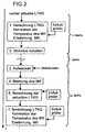
- the calculation of the load temperature parameter LTKG in step 1 ' is carried out analogously to the calculation from step 1 with modified ones Ambient conditions, for example a higher ambient temperature measurement.
- the current load temperature parameter LTKG in the second operating phase 2.BtrPh may be from the first operating phase 1.BtrPh for a short standby phase BrtPh increased significantly.
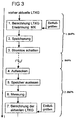
- FIG. 3 shows an alternative, second schematic representation of a time sequence for Calculation of a load temperature parameter LTKG shown.
- No algorithm is used for the load temperature parameter LTKG from FIG. 2.
- Several Standard measured values are for different temperatures of a temperature range stored in a table in the control device.
- the standard measured values through various influencing variables, for example the ambient temperature measurement variable, weighted.
- Intermediate values of the standard measured values for example, linearly interpolated.
- a separate measuring body MK which serves exclusively as a reference body, becomes independent from the energization of the electric motor by one of the control device controlled separate heating current heated to a predetermined temperature based on a known cooling behavior, a time interval (duration of the standby phase) to investigate.
- the heating power for heating the measuring body MK is controlled by the separate heating current from the control device.
- the default Temperature is varied based on the ambient temperature, so that one for the Analysis of the cooling of the electric motor sufficiently long time interval over the cooling of the separate measuring body MK can be determined.
- the load temperature parameter LTKG and the specified temperature of the measuring body MK are stored in a non-volatile memory of the control device in step 2. If several electric motors are monitored by the control device, the calculated load temperature parameter LTKG of each electric motor is saved and in step 3 the control device is switched to essentially zero current (analog FIG 2).
- FIG. 4 shows an alternative third schematic representation of a time sequence for Calculation of a load temperature parameter LTKG shown.
- the control device SV is connected to a central module ZM as an electronic module via a system bus. Between the central module ZM and the control device SV Data exchanged using a protocol. A data word sent over the system bus has a head for addressing the control device and data with a Data identifier for assigning the data, for example a system time SU1 or SU2.
- the data identifier contains a bit sequence on the basis of which the control device detects that the received data is a sent system time SU1 or SU2.
- FIG. 2 or FIG. 3 additionally turns into the heat capacity of the electric motor evaluated as a delay in warming.
- the ambient temperature is measured measured from the temperature in the vicinity of the control device SV and a characteristic value for the switch-off time of the control device SV Ambient temperature measurement variable saved in step 4.
- step 2 the control device SV previously requests this from the via the system bus Central module ZM the first system time SU1 as the second parameter, which in step 3 transmitted to the control device SV via the system bus and there in step 4 is also saved.
- An algorithm characteristic of the cooling of the electric motor is used for the evaluation used, which includes all environmental parameters of the electric motor. For example can also easily change a changing ambient temperature be included as variable in the exponential factor.
- the parameters of the algorithm for example, a logarithmic factor or a proportional factor are used for an electric motor type based on a heat capacity and a heat transfer resistance to the surrounding air and are stored in a memory (ROM) of the control device saved.
- the ambient temperature measurement is also called Temperature-dependent influencing variable of the algorithm for calculating the load temperature parameter LTKG, for example through the aforementioned inclusion in the exponential factor, evaluated.
- the parameters of the Algorithm and also the type of algorithm correspondingly changed environmental conditions with changed parameters and the algorithm is newly formed. So it turns from electric motor specific Characteristic values and, for example, the ambient temperature measurement Aligned parameters and factors of the algorithm.
- the cooling behavior is determined by the interpolation of standard measured values.
Landscapes
- Control Of Electric Motors In General (AREA)
- Protection Of Generators And Motors (AREA)
- Electric Propulsion And Braking For Vehicles (AREA)
- Thermally Actuated Switches (AREA)
- Fuses (AREA)
- Testing Electric Properties And Detecting Electric Faults (AREA)
Description
- FIG 1
- eine schematische Abfolge einer Aktivierung und thermischen Überwachung eines Lastelementes,
- FIG 2
- eine erste schematische Darstellung einer zeitlichen Abfolge zur Berechnung einer Lasttemperaturkenngröße,
- FIG 3
- eine zweite schematische Darstellung einer zeitlichen Abfolge zur Berechnung einer Lasttemperaturkenngröße, und
- FIG 4
- eine dritte schematische Darstellung einer zeitlichen Abfolge zur Berechnung einer Lasttemperaturkenngröße.
- LTKG
- Lasttemperaturkenngröße, Temperatur des Lasttelementes
- S2
- Unterer Schwellwert zur Temperaturüberwachung
- S1
- Oberer Schwellwert zur Temperaturüberwachung
- MK
- Meßkörper, Kühlkörper
- 1.BtrPh
- erste Betriebsphase
- 2.BtrPh
- zweite Betriebsphase
- BrtPh
- Bereitschaftsphase, Sleep-mode
- ZM
- Zentralmodul, Systemuhr
- SV
- Steuerungsvorrichtung
- SU1
- Systemuhrzeit zum Abschaltzeitpunkt
- SU2
- Systemuhrzeit zum Einschaltzeitpunkt
- System-BUS
- Systembus
Claims (16)
- Verfahren zur Überwachung auf thermische Überlastung eines elektrischen Lastelementes in einem Kraftfahrzeug mit weiteren elektrischen Verbrauchern, die innerhalb einer Betriebsphase zumindest teilweise bestromt werden, bei dem
die Überwachung des Lastelementes durch eine Steuerungsvorrichtung zumindest anhand einer berechneten Lasttemperaturkenngröße erfolgt,
wobeiwährend einer ersten Betriebsphase der Steuerungsvorrichtung zur Berechnung der Lasttemperaturkenngröße eine Verlustleistung des Lastelementes oder eine hierzu im wesentlichen proportionale Größe ausgewertet wird,während einer oder mehrerer Bereitschaftsphasen der Steuerungsvorrichtung zwischen der ersten Betriebsphase und einer zweiten Betriebsphase die Steuerungsvorrichtung im wesentlichen stromlos geschaltet wird, so dass keine Auswertung der Lasttemperaturkenngröße möglich ist, undnach einem Einschalten der Steuerungsvorrichtung in der zweiten Betriebsphase der Steuerungsvorrichtung zur Berechnung der aktuellen Lasttemperaturkenngröße mindestens eine erste Kenngröße ausgewertet wird, die den Einschaltzeitpunkt der Steuerungsvorrichtung charakterisiert. - Verfahren nach Anspruch 1, wobei
mindestens eine für einen Abschaltzeitpunkt der ersten Betriebsphase charakteristische zweite Kenngröße in einem nichtflüchtigen Speicher gespeichert wird, und
zur Berechnung der Lasttemperaturkenngröße die erste Kenngröße und die zweite Kenngröße ausgewertet werden. - Verfahren nach einem der Ansprüche 1 oder 2, wobei
die erste Kenngröße über eine Datenverbindung von einem Elektronikmodul des Kraftfahrzeugs zur Steuerungsvorrichtung übertragen wird. - Verfahren nach Anspruch 3, wobei
als erste Kenngröße eine Zeitkennung von einer Systemuhr über die Datenverbindung an die Steuerungsvorrichtung übermittelt wird. - Verfahren nach Anspruch 4, wobei
die Zeitkennung zyklisch übermittelt wird. - Verfahren nach Anspruch 4, wobei
die Zeitkennung für den Einschaltzeitpunkt übermittelt wird. - Verfahren nach Anspruch 6, wobei
die Datenverbindung ein Systembus ist, über den mittels eines Datenprotokolls die Zeitkennung an die Steuerungsvorrichtung adressiert wird. - Verfahren nach Anspruch 7, wobei
die Steuerungsvorrichtung die Zeitkennung über ein Datenprotokoll von dem Elektronikmodul anfordert. - Verfahren nach Anspruch 2 und einem der Ansprüche 3 bis 8, wobei
mehrere Lastelemente von der Steuerungsvorrichtung überwacht werden, und zur Berechnung die Lasttemperaturkenngrößen zum Abschaltzeitpunkt und der Abschaltzeitpunkt gespeichert und zum Einschaltzeitpunkt ausgewertet werden. - Verfahren nach Anspruch 3, wobei
ein Endwert der Lasttemperaturkenngröße zum Abschaltzeitpunkt der ersten Betriebsphase Ober einen Systembus als Datenverbindung von der Steuerungsvorrichtung an das Elektronikmodul übermittelt wird und mit einem ersten Zeitwert im Elektronikmodul gespeichert wird, und
nach dem Einschaltzeitpunkt der erste Zeitwert und der den Einschaltzeitpunkt charakterisierende zweite Zeitwert oder eine Differenz der Zeitwerte, sowie der Endwert von dem Elektronikmodul an die Steuerungsvorrichtung übermittelt wird. - Verfahren nach Anspruch 10, wobei
in einem Datenprotokoll Lastelementkennungen über den Systembus übermittelt werden, und
der übertragene erste Zeitwert, zweite Zeitwert und der Endwert den Lastelementkennungen zugeordnet werden. - Verfahren nach einem der vorhergehenden Ansprüche, wobei
eine Umgebungstemperaturmeßgröße aus der Temperatur in der Nähe der Steuerungsvorrichung gemessen wird, und
ein für den Einschaltzeitpunkt charakteristischer erster Wert der Umgebungstemperaturmeßgröße als eine der ersten Kenngrößen ausgewertet wird. - Verfahren nach den Ansprüchen 2 und 12, wobei
ein für den Abschaltzeitpunkt charakteristischer zweiter Wert der Umgebungstemperaturmeßgröße als eine der zweiten Kenngrößen gemessen wird. - Verfahren nach einem der Ansprüche 12 oder 13, wobei
anhand der aktuellen Lasttemperaturkenngröße und der Umgebungstemperaturmeßgröße für Abweichungen unterhalb eines Schwellwertes (zur Meßgenauigkeit) die Lasttemperaturkenngröße gleich der Umgebungstemperaturmeßgröße gesetzt wird. - Verfahren nach einem der vorhergehenden Ansprüche, wobei
für ein Zeitintervall zwischen der ersten Betriebsphase und dem Einschaltzeitpunkt, das größer einem Zeitschwellwert ist, die Lasttemperaturkenngröße gleich der Umgebungstemperaturmeßgröße gesetzt wird. - Verfahren nach einem der vorhergehenden Ansprüche, wobei
im Falle einer Überhitzung eine Fehlermeldung an ein zentrales Diagnosemodul übermittelt wird, und
zusätzlich die Funktion eines Thermoschalters überwacht wird, so daß ein Fehler in der Zuteilung von einem Ansprechen eines Thermoschalters wegen thermischer Überlastung unterschieden wird.
Applications Claiming Priority (3)
| Application Number | Priority Date | Filing Date | Title |
|---|---|---|---|
| DE10026057 | 2000-05-25 | ||
| DE10026057A DE10026057A1 (de) | 2000-05-25 | 2000-05-25 | Thermische Überwachung eines elektrischen Lastelementes |
| PCT/DE2001/001608 WO2001091264A1 (de) | 2000-05-25 | 2001-04-25 | Thermische überwachung eines elektrischen lastelementes |
Publications (2)
| Publication Number | Publication Date |
|---|---|
| EP1284039A1 EP1284039A1 (de) | 2003-02-19 |
| EP1284039B1 true EP1284039B1 (de) | 2003-12-17 |
Family
ID=7643622
Family Applications (1)
| Application Number | Title | Priority Date | Filing Date |
|---|---|---|---|
| EP01942982A Expired - Lifetime EP1284039B1 (de) | 2000-05-25 | 2001-04-25 | Thermische überwachung eines elektrischen lastelementes |
Country Status (6)
| Country | Link |
|---|---|
| US (1) | US6897782B2 (de) |
| EP (1) | EP1284039B1 (de) |
| AT (1) | ATE256929T1 (de) |
| DE (2) | DE10026057A1 (de) |
| ES (1) | ES2213701T3 (de) |
| WO (1) | WO2001091264A1 (de) |
Families Citing this family (15)
| Publication number | Priority date | Publication date | Assignee | Title |
|---|---|---|---|---|
| DE10048704B4 (de) * | 2000-09-30 | 2014-07-10 | Sew-Eurodrive Gmbh & Co Kg | Verfahren für eine Vorrichtung mit Leistungshalbleitern und Vorrichtung |
| DE102004043059A1 (de) * | 2004-09-06 | 2006-03-09 | Kriwan Industrie-Elektronik Gmbh | Verfahren und Schutzschaltung zur Temperaturüberwachung von kältemittelgekühlten Elektromotoren |
| US7526400B2 (en) * | 2005-04-14 | 2009-04-28 | International Business Machines Corporation | Thermal modeling and error detection in a data processing configuration |
| JP2007014057A (ja) * | 2005-06-28 | 2007-01-18 | Asmo Co Ltd | モータ制御装置 |
| JP4679281B2 (ja) * | 2005-07-15 | 2011-04-27 | アスモ株式会社 | モータ制御装置およびモータ推定温度の算出方法 |
| DE102006029766A1 (de) * | 2006-06-27 | 2008-01-03 | Geze Gmbh | Antrieb für eine Tür oder ein Fenster |
| US20080297011A1 (en) * | 2007-06-01 | 2008-12-04 | Delaney Daniel E | Integrated controller/motor with thermal overload sensor |
| KR101261946B1 (ko) * | 2010-12-02 | 2013-05-09 | 현대자동차주식회사 | 하이브리드 차량용 구동 모터를 냉각하는 냉각 장치 및 이를 제어하는 방법 |
| US9018804B2 (en) * | 2011-03-30 | 2015-04-28 | Continental Automotive Systems, Inc. | Controlling of a power state under extreme temperatures |
| JP6099156B2 (ja) * | 2011-05-24 | 2017-03-22 | オーバーヘッド ドア コーポレーション | バリア・オペレータ・システム及び動作方法 |
| US9130368B2 (en) * | 2013-02-14 | 2015-09-08 | Deere & Company | Overload prevention system to improve intermittent load capacity of electric drive applications |
| US9425729B2 (en) | 2013-03-15 | 2016-08-23 | Honda Motor Co., Ltd. | Motor control devices and methods |
| DE102013215542A1 (de) * | 2013-08-07 | 2014-09-18 | Zf Friedrichshafen Ag | Verfahren zur Optimierung des Betriebsverhaltens eines mechatronischen Systems, insbesondere eines Automatgetriebes eines Kraftfahrzeugs umfassend zumindest ein eine Speichermöglichkeit aufweisendes Steuergerät ohne eigene Systemzeit und zumindest ein Steuergerät mit eigener Systemzeit |
| US12334253B2 (en) * | 2021-06-04 | 2025-06-17 | Florida State University | Systems and methods for leadless power coupling for cryogenic environments |
| CN121099590B (zh) * | 2025-11-12 | 2026-03-03 | 苏州标品杰电子科技有限公司 | 模块化耐高温电源系统及其宽温域主动热管理方法 |
Family Cites Families (9)
| Publication number | Priority date | Publication date | Assignee | Title |
|---|---|---|---|---|
| US5081586A (en) * | 1990-02-20 | 1992-01-14 | Eaton Corporation | Multiplexing of accessories in a vehicle |
| DE4038198A1 (de) * | 1990-11-30 | 1992-07-02 | Brose Fahrzeugteile | Verfahren und vorrichtung zur erfassung und/oder regelung der temperatur elektrischer oder elektronischer bauteile oder baugruppen |
| DE4109867C2 (de) * | 1991-03-26 | 1996-05-30 | Bosch Gmbh Robert | Schutzeinrichtung für Elektromotoren |
| DE4216040A1 (de) | 1992-05-15 | 1993-11-18 | Bosch Gmbh Robert | Verfahren zur Überwachung eines Elektromotors auf thermische Überlastung |
| DE4315182A1 (de) * | 1993-05-07 | 1994-11-10 | Bosch Gmbh Robert | Elektromotorischer Antrieb |
| ES2239810T3 (es) * | 1997-09-18 | 2005-10-01 | Robert Bosch Gmbh | Accionamiento por motor electrico. |
| DE19742930C1 (de) * | 1997-09-29 | 1998-11-19 | Siemens Ag | Leistungsschalter mit Überlastschutz |
| US6198995B1 (en) * | 1998-03-31 | 2001-03-06 | Lear Automotive Dearborn, Inc. | Sleep mode for vehicle monitoring system |
| EP0999630A1 (de) * | 1998-11-06 | 2000-05-10 | ABB Research Ltd. | Schutzeinrichtung gegen Wärmeüberlastung eines Elektromotors und entsprechendes Verfahren |
-
2000
- 2000-05-25 DE DE10026057A patent/DE10026057A1/de not_active Ceased
-
2001
- 2001-04-25 AT AT01942982T patent/ATE256929T1/de not_active IP Right Cessation
- 2001-04-25 WO PCT/DE2001/001608 patent/WO2001091264A1/de not_active Ceased
- 2001-04-25 EP EP01942982A patent/EP1284039B1/de not_active Expired - Lifetime
- 2001-04-25 US US10/296,634 patent/US6897782B2/en not_active Expired - Fee Related
- 2001-04-25 ES ES01942982T patent/ES2213701T3/es not_active Expired - Lifetime
- 2001-04-25 DE DE50101205T patent/DE50101205D1/de not_active Expired - Lifetime
Also Published As
| Publication number | Publication date |
|---|---|
| US20040061481A1 (en) | 2004-04-01 |
| EP1284039A1 (de) | 2003-02-19 |
| WO2001091264A1 (de) | 2001-11-29 |
| ATE256929T1 (de) | 2004-01-15 |
| DE50101205D1 (de) | 2004-01-29 |
| DE10026057A1 (de) | 2001-11-29 |
| ES2213701T3 (es) | 2004-09-01 |
| US6897782B2 (en) | 2005-05-24 |
Similar Documents
| Publication | Publication Date | Title |
|---|---|---|
| EP1284039A1 (de) | Thermische überwachung eines elektrischen lastelementes | |
| DE112018007053T5 (de) | In einem Fahrzeug angebrachte Ladevorrichtung und Steuerverfahren für eine in einem Fahrzeug angebrachte Ladevorrichtung | |
| DE102006052135A1 (de) | Rücksetzbare Schaltkreisschutz-Vorrichtung | |
| DE10332625A1 (de) | Diagnosegerät für das elektrische System von Kraftfahrzeugen | |
| DE102005022204A1 (de) | Batterietemperatursteuerung für Fahrzeuge | |
| DE102006019625A1 (de) | Steuereinrichtung für einen Kraftfahrzeuggenerator mit der Fähigkeit der genauen Erfassung der Temperatur des Generators | |
| DE102020125642A1 (de) | System, Verfahren und Computerprogrammprodukt zur Überwachung der Kühlleistung für einen Halbleiter-Pulswechselrichter | |
| EP0559726B1 (de) | Verfahren und vorrichtung zur ermittlung der belastung und/oder der belastbarkeit elektronisch geregelter bauteile oder baugruppen | |
| EP2609322B1 (de) | Verfahren und vorrichtung zum betreiben eines starters eines fahrzeugs | |
| WO2017108556A1 (de) | Verfahren zum betrieb eines elektromotorischen kältemittelverdichters | |
| DE102009025078A1 (de) | Verfahren zur Berechnung der Temperatur wenigstens einer Komponente einer mehrere Komponenten aufweisenden elektrischen oder elektronischen Baugruppe | |
| EP1104719A2 (de) | Stromversorgung für Fahrzeuge | |
| EP3687850A1 (de) | Verfahren zur ermittlung einer temperatur einer aktiven schicht eines heizwiderstands | |
| DE102006033044A1 (de) | Vorrichtung zum Überlastschutz eines Versorgungsstrangs für eine elektrische Last in einem Kraftfahrzeug | |
| DE102013006092B4 (de) | Steuergerät und Verfahren zur Reduktion eines Anwendererlebnisses von Koppeleffekten innerhalb eines elektrischen Netzes | |
| DE102012004526A1 (de) | Verfahren für den Betrieb einer Heizung eines Sitzes eines Kraftfahrzeugs | |
| EP2469070B1 (de) | Begrenzung des Startspannungseinbruchs in einem Kraftfahrzeug-Bordnetz | |
| WO1999014835A1 (de) | Elektromotorischer antrieb | |
| DE102020213929B4 (de) | Energieversorgungssystem | |
| DE102016123063B4 (de) | Verfahren und ansteuereinrichtung zum sequenzgesteuerten ansteuern von lasten an einem stromverteiler für ein kraftfahrzeug | |
| DE69228871T2 (de) | Elektrischer Lastdetektor und Verfahren und Vorrichtung zu dessen Verwendung | |
| WO2024132521A1 (de) | System zur absicherung einer last eines niedervolt-bordnetzes | |
| EP1630923B1 (de) | Steuerschaltung für eine Mehrzahl elektrischer Verbraucher mit einer Absicherung für Halbleiterschalter | |
| EP1349428B1 (de) | Heizkörper und Verfahren zur Steuerung eines Heizkörpers, insbesondere für ein Kraftfahrzeug | |
| EP4354732A1 (de) | Verfahren und vorrichtung zum betrieb eines leistungshalbleiterelements |
Legal Events
| Date | Code | Title | Description |
|---|---|---|---|
| PUAI | Public reference made under article 153(3) epc to a published international application that has entered the european phase |
Free format text: ORIGINAL CODE: 0009012 |
|
| 17P | Request for examination filed |
Effective date: 20021111 |
|
| AK | Designated contracting states |
Designated state(s): AT BE CH CY DE DK ES FI FR GB GR IE IT LI LU MC NL PT SE TR |
|
| RIN1 | Information on inventor provided before grant (corrected) |
Inventor name: HUHN, MICHAEL Inventor name: NICOLAI, STEFFEN Inventor name: HEINRICH, PETER Inventor name: EHRENPFORDT, JOCHEN Inventor name: PREIS, KARL-HEINZ |
|
| GRAH | Despatch of communication of intention to grant a patent |
Free format text: ORIGINAL CODE: EPIDOS IGRA |
|
| GRAS | Grant fee paid |
Free format text: ORIGINAL CODE: EPIDOSNIGR3 |
|
| GRAA | (expected) grant |
Free format text: ORIGINAL CODE: 0009210 |
|
| AK | Designated contracting states |
Kind code of ref document: B1 Designated state(s): AT BE CH CY DE DK ES FI FR GB GR IE IT LI LU MC NL PT SE TR |
|
| PG25 | Lapsed in a contracting state [announced via postgrant information from national office to epo] |
Ref country code: NL Free format text: LAPSE BECAUSE OF FAILURE TO SUBMIT A TRANSLATION OF THE DESCRIPTION OR TO PAY THE FEE WITHIN THE PRESCRIBED TIME-LIMIT Effective date: 20031217 Ref country code: IE Free format text: LAPSE BECAUSE OF FAILURE TO SUBMIT A TRANSLATION OF THE DESCRIPTION OR TO PAY THE FEE WITHIN THE PRESCRIBED TIME-LIMIT Effective date: 20031217 Ref country code: CY Free format text: LAPSE BECAUSE OF FAILURE TO SUBMIT A TRANSLATION OF THE DESCRIPTION OR TO PAY THE FEE WITHIN THE PRESCRIBED TIME-LIMIT Effective date: 20031217 Ref country code: FI Free format text: LAPSE BECAUSE OF FAILURE TO SUBMIT A TRANSLATION OF THE DESCRIPTION OR TO PAY THE FEE WITHIN THE PRESCRIBED TIME-LIMIT Effective date: 20031217 Ref country code: TR Free format text: LAPSE BECAUSE OF FAILURE TO SUBMIT A TRANSLATION OF THE DESCRIPTION OR TO PAY THE FEE WITHIN THE PRESCRIBED TIME-LIMIT Effective date: 20031217 |
|
| REG | Reference to a national code |
Ref country code: GB Ref legal event code: FG4D Free format text: NOT ENGLISH |
|
| REG | Reference to a national code |
Ref country code: CH Ref legal event code: EP |
|
| REG | Reference to a national code |
Ref country code: IE Ref legal event code: FG4D Free format text: GERMAN |
|
| REF | Corresponds to: |
Ref document number: 50101205 Country of ref document: DE Date of ref document: 20040129 Kind code of ref document: P |
|
| GBT | Gb: translation of ep patent filed (gb section 77(6)(a)/1977) |
Effective date: 20040209 |
|
| PG25 | Lapsed in a contracting state [announced via postgrant information from national office to epo] |
Ref country code: GR Free format text: LAPSE BECAUSE OF FAILURE TO SUBMIT A TRANSLATION OF THE DESCRIPTION OR TO PAY THE FEE WITHIN THE PRESCRIBED TIME-LIMIT Effective date: 20040317 Ref country code: DK Free format text: LAPSE BECAUSE OF FAILURE TO SUBMIT A TRANSLATION OF THE DESCRIPTION OR TO PAY THE FEE WITHIN THE PRESCRIBED TIME-LIMIT Effective date: 20040317 Ref country code: SE Free format text: LAPSE BECAUSE OF FAILURE TO SUBMIT A TRANSLATION OF THE DESCRIPTION OR TO PAY THE FEE WITHIN THE PRESCRIBED TIME-LIMIT Effective date: 20040317 |
|
| RAP2 | Party data changed (patent owner data changed or rights of a patent transferred) |
Owner name: BROSE FAHRZEUGTEILE GMBH & CO. KG, COBURG |
|
| PG25 | Lapsed in a contracting state [announced via postgrant information from national office to epo] |
Ref country code: LU Free format text: LAPSE BECAUSE OF NON-PAYMENT OF DUE FEES Effective date: 20040425 Ref country code: AT Free format text: LAPSE BECAUSE OF NON-PAYMENT OF DUE FEES Effective date: 20040425 |
|
| PG25 | Lapsed in a contracting state [announced via postgrant information from national office to epo] |
Ref country code: MC Free format text: LAPSE BECAUSE OF NON-PAYMENT OF DUE FEES Effective date: 20040430 Ref country code: BE Free format text: LAPSE BECAUSE OF NON-PAYMENT OF DUE FEES Effective date: 20040430 |
|
| NLT2 | Nl: modifications (of names), taken from the european patent patent bulletin |
Owner name: BROSE FAHRZEUGTEILE GMBH & CO. KG, COBURG |
|
| NLV1 | Nl: lapsed or annulled due to failure to fulfill the requirements of art. 29p and 29m of the patents act | ||
| REG | Reference to a national code |
Ref country code: GB Ref legal event code: ERR Free format text: NOTIFICATION HAS NOW BEEN RECEIVED FROM THE EUROPEAN PATENT OFFICE THAT THE CORRECT NAME OF THE PROPRIETOR IS: BROSE FAHRZEUGTEILE GMBH & CO.KG COBURG THIS CORRECTION WAS PUBLISHED IN EUROPEAN PATENT BULLETIN 04/12 OF 20040317. |
|
| REG | Reference to a national code |
Ref country code: IE Ref legal event code: FD4D |
|
| REG | Reference to a national code |
Ref country code: ES Ref legal event code: FG2A Ref document number: 2213701 Country of ref document: ES Kind code of ref document: T3 |
|
| ET | Fr: translation filed | ||
| PLBE | No opposition filed within time limit |
Free format text: ORIGINAL CODE: 0009261 |
|
| STAA | Information on the status of an ep patent application or granted ep patent |
Free format text: STATUS: NO OPPOSITION FILED WITHIN TIME LIMIT |
|
| BERE | Be: lapsed |
Owner name: *BROSE FAHRZEUGTEILE G.M.B.H. & CO. K.G. COBOURG Effective date: 20040430 |
|
| 26N | No opposition filed |
Effective date: 20040920 |
|
| PG25 | Lapsed in a contracting state [announced via postgrant information from national office to epo] |
Ref country code: LI Free format text: LAPSE BECAUSE OF NON-PAYMENT OF DUE FEES Effective date: 20050430 Ref country code: CH Free format text: LAPSE BECAUSE OF NON-PAYMENT OF DUE FEES Effective date: 20050430 |
|
| REG | Reference to a national code |
Ref country code: CH Ref legal event code: PL |
|
| PG25 | Lapsed in a contracting state [announced via postgrant information from national office to epo] |
Ref country code: PT Free format text: LAPSE BECAUSE OF NON-PAYMENT OF DUE FEES Effective date: 20040517 |
|
| PGFP | Annual fee paid to national office [announced via postgrant information from national office to epo] |
Ref country code: GB Payment date: 20120425 Year of fee payment: 12 |
|
| PGFP | Annual fee paid to national office [announced via postgrant information from national office to epo] |
Ref country code: IT Payment date: 20120421 Year of fee payment: 12 |
|
| PGFP | Annual fee paid to national office [announced via postgrant information from national office to epo] |
Ref country code: ES Payment date: 20120510 Year of fee payment: 12 |
|
| GBPC | Gb: european patent ceased through non-payment of renewal fee |
Effective date: 20130425 |
|
| PG25 | Lapsed in a contracting state [announced via postgrant information from national office to epo] |
Ref country code: GB Free format text: LAPSE BECAUSE OF NON-PAYMENT OF DUE FEES Effective date: 20130425 |
|
| PG25 | Lapsed in a contracting state [announced via postgrant information from national office to epo] |
Ref country code: IT Free format text: LAPSE BECAUSE OF NON-PAYMENT OF DUE FEES Effective date: 20130425 |
|
| REG | Reference to a national code |
Ref country code: ES Ref legal event code: FD2A Effective date: 20140708 |
|
| PG25 | Lapsed in a contracting state [announced via postgrant information from national office to epo] |
Ref country code: ES Free format text: LAPSE BECAUSE OF NON-PAYMENT OF DUE FEES Effective date: 20130426 |
|
| REG | Reference to a national code |
Ref country code: FR Ref legal event code: PLFP Year of fee payment: 15 |
|
| PGFP | Annual fee paid to national office [announced via postgrant information from national office to epo] |
Ref country code: DE Payment date: 20150430 Year of fee payment: 15 |
|
| PGFP | Annual fee paid to national office [announced via postgrant information from national office to epo] |
Ref country code: FR Payment date: 20150408 Year of fee payment: 15 |
|
| REG | Reference to a national code |
Ref country code: DE Ref legal event code: R119 Ref document number: 50101205 Country of ref document: DE |
|
| REG | Reference to a national code |
Ref country code: FR Ref legal event code: ST Effective date: 20161230 |
|
| PG25 | Lapsed in a contracting state [announced via postgrant information from national office to epo] |
Ref country code: DE Free format text: LAPSE BECAUSE OF NON-PAYMENT OF DUE FEES Effective date: 20161101 Ref country code: FR Free format text: LAPSE BECAUSE OF NON-PAYMENT OF DUE FEES Effective date: 20160502 |