EP1283412A2 - Verfahren und Vorrichtung zum Erfassen eines Befüllvorganges - Google Patents
Verfahren und Vorrichtung zum Erfassen eines Befüllvorganges Download PDFInfo
- Publication number
- EP1283412A2 EP1283412A2 EP02011726A EP02011726A EP1283412A2 EP 1283412 A2 EP1283412 A2 EP 1283412A2 EP 02011726 A EP02011726 A EP 02011726A EP 02011726 A EP02011726 A EP 02011726A EP 1283412 A2 EP1283412 A2 EP 1283412A2
- Authority
- EP
- European Patent Office
- Prior art keywords
- parameter
- parameters
- filling process
- echo
- amplitude
- Prior art date
- Legal status (The legal status is an assumption and is not a legal conclusion. Google has not performed a legal analysis and makes no representation as to the accuracy of the status listed.)
- Granted
Links
- 238000000034 method Methods 0.000 title claims abstract description 25
- 238000005429 filling process Methods 0.000 title claims description 33
- 239000000463 material Substances 0.000 claims abstract description 6
- 238000011156 evaluation Methods 0.000 claims description 10
- 238000005259 measurement Methods 0.000 claims description 8
- 238000002604 ultrasonography Methods 0.000 claims 1
- 230000000977 initiatory effect Effects 0.000 abstract 1
- 238000002592 echocardiography Methods 0.000 description 7
- 238000001514 detection method Methods 0.000 description 5
- 238000013461 design Methods 0.000 description 2
- 239000000428 dust Substances 0.000 description 2
- 239000000945 filler Substances 0.000 description 2
- 230000007774 longterm Effects 0.000 description 2
- 238000010079 rubber tapping Methods 0.000 description 2
- 238000010521 absorption reaction Methods 0.000 description 1
- 230000002238 attenuated effect Effects 0.000 description 1
- 230000001419 dependent effect Effects 0.000 description 1
- 238000009795 derivation Methods 0.000 description 1
- 238000011161 development Methods 0.000 description 1
- 230000018109 developmental process Effects 0.000 description 1
- 238000010586 diagram Methods 0.000 description 1
- 230000009969 flowable effect Effects 0.000 description 1
- 238000012544 monitoring process Methods 0.000 description 1
- 239000002245 particle Substances 0.000 description 1
- 238000005070 sampling Methods 0.000 description 1
Images

Classifications
-
- G—PHYSICS
- G01—MEASURING; TESTING
- G01F—MEASURING VOLUME, VOLUME FLOW, MASS FLOW OR LIQUID LEVEL; METERING BY VOLUME
- G01F23/00—Indicating or measuring liquid level or level of fluent solid material, e.g. indicating in terms of volume or indicating by means of an alarm
- G01F23/22—Indicating or measuring liquid level or level of fluent solid material, e.g. indicating in terms of volume or indicating by means of an alarm by measuring physical variables, other than linear dimensions, pressure or weight, dependent on the level to be measured, e.g. by difference of heat transfer of steam or water
- G01F23/28—Indicating or measuring liquid level or level of fluent solid material, e.g. indicating in terms of volume or indicating by means of an alarm by measuring physical variables, other than linear dimensions, pressure or weight, dependent on the level to be measured, e.g. by difference of heat transfer of steam or water by measuring the variations of parameters of electromagnetic or acoustic waves applied directly to the liquid or fluent solid material
- G01F23/296—Acoustic waves
- G01F23/2965—Measuring attenuation of transmitted waves
-
- G—PHYSICS
- G01—MEASURING; TESTING
- G01F—MEASURING VOLUME, VOLUME FLOW, MASS FLOW OR LIQUID LEVEL; METERING BY VOLUME
- G01F23/00—Indicating or measuring liquid level or level of fluent solid material, e.g. indicating in terms of volume or indicating by means of an alarm
- G01F23/22—Indicating or measuring liquid level or level of fluent solid material, e.g. indicating in terms of volume or indicating by means of an alarm by measuring physical variables, other than linear dimensions, pressure or weight, dependent on the level to be measured, e.g. by difference of heat transfer of steam or water
- G01F23/28—Indicating or measuring liquid level or level of fluent solid material, e.g. indicating in terms of volume or indicating by means of an alarm by measuring physical variables, other than linear dimensions, pressure or weight, dependent on the level to be measured, e.g. by difference of heat transfer of steam or water by measuring the variations of parameters of electromagnetic or acoustic waves applied directly to the liquid or fluent solid material
- G01F23/284—Electromagnetic waves
Definitions
- the present invention relates to a method and a Device for detecting a filling process.
- Echo signal conditions When such a container is filled, they change Echo signal conditions. Through dust or filling material particles in the air, the signals may be attenuated. The amplitude of the false echo signals as well as the echo signal the level of the product changes; Contents can be on the container walls stick or fall off of them, so that Information about false echo contributions leading to an earlier one Time have been collected during and after filling no longer necessarily have to be valid. In particular if the signals used acoustic signals the noise of the filling process can be the echo signal overlay and hide echo contributions. The filling flow too himself can, if he of the emitted signal hit, provide false echo signals.
- the evaluation of the echo signals automatically in a Evaluation unit should be made, it is therefore required, this one in addition to the echo signal Feed information about whether a filling process is in progress takes place or not.
- Such information can e.g. are obtained by tapping an actuating signal that the open or closed state of a filler flap of the Container controls, from a control device of the filler flap or by a position sensor arranged on the flap. In both cases, the Container or its control device for tapping the the necessary signals are prepared or that there are structural Changes are made.
- the object of the present invention is a method for Detection of a filling process in a container and a Device for performing the method to specify the do not make such demands on the container.
- amplitude values of the Echo signals used. After a simple design of the The method can be at least one at a time at a given interval from the time of sending the Act the signal measured amplitude value.
- the amplitude value can also span the entire extent or one or averaged several intervals over time of the echo be to improve the reliability of the assessment.
- the extent of the amplitude fluctuations is also suitable as a parameter in the course of the echo signals. This are relatively low when the echo signals are of a strong Noise of the filling process are superimposed or echo signals thrown back from the container by a Fill jet be dampened.
- Such a parameter can be obtained in a simple manner by adding differences from to successive Measured values of the amplitude recorded at points in time of the echo signals.
- the echo amplitude generally changes over time the emission of the signal drops, it is useful when Calculate the parameter to add only those differences where the amplitude of the later measured value is higher is than that of the previous one.
- Another way is as a parameter a weighted sum of amplitude values form the echo signal at different times. there is preferably one in the time course of the echo signal increasing weighting factor selected.
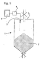
- the level measuring device comprises in a manner known per se one mounted inside the container 1 on the ceiling 2 Transmitter / receiver unit 3, one with the transmitter / receiver unit 3 connected evaluation unit 4 and one Display unit 5, e.g. a picture tube.
- the evaluation unit 4 can be suitable as assigned to the transmitter / receiver unit 3 programmed microprocessor implemented; it can also be an unspecialized computer act with the transmitter / receiver unit 3 via a Interface (not shown) communicates and in the Is able to run a program that follows one Realized process to be described in more detail.
- the Transmitter / receiver unit 3 sends a signal, in particular an ultrasonic signal, in the lower area of the container 1, where a filling material 7 to be detected is located and received one of the filling material 7 and of the walls of the container 1 returned echo signal.
- Fig. 2 is a graph showing a typical course of a shows such an echo signal.
- the abscissa is the covered the duration of the echo signal Path length in meters and on the ordinate the amplitude of the Echo signal plotted in decibels.
- Two curves 10, 11 show the typical time course of an echo signal in each case in the non-filling mode of the container or at one ongoing filling process. The comparison of the two curves shows that the signal amplitude curve of the filling process corresponding curve 11 is lower overall and also has fewer details.
- An alternative way to set an expectation range for Determining the echo signal amplitude is based on the analysis from false echoes. Such contributions are called false echoes of the echo signal, which is independent of the actual Level in the container occur, and as a result due to reflections on the container walls are.
- the curve 12 in FIG. 3 shows the course of such false echoes as a function of path length. Because the false echo curve to that Corresponds to the proportion of the echo signals that is not dependent on the fill level is variable, it only has a relatively short path length, 3 below about 8 m, a not negligible amplitude. It is in a store the evaluation unit 4 and is saved by the Evaluation unit 4 with periodically recorded during operation Echo signals compared.
- Evaluation unit 4 comprise a low-pass filter in which the Filtered echo signal before comparison with curve 13 becomes.
- a plurality of sample values h (t1), h (t2), ... of the echo signal are recorded, the sampling instants t 1 , t 2 , ... with a predetermined step size Dt, and for each echo signal the sum calculated, where the function p (x) has the value x for positive x and otherwise the value 0.
- Fig. 4 shows a curve 14 formed from a sequence of Values of this sum R, which on a container in the course of a Time was recorded during which filling processes took place and alternated stages without filling the container. you clearly recognizes that the values of the sum R clearly in two separate value ranges S1, S2, depending on whether a filling process is running, as in the intervals d1, d3, d5, or not, as in the intervals d2, d4.
- the security of the recording of filling processes can improve even further.
- the Fig. 2 that the difference in the amplitudes of the echo signals with and without filling at short distances is small and tends to grow with distance. This You can take advantage of behavior by not doing it directly compares the amplitude of the echo signals, but that Product of echo signal amplitude and delay time forms and then current values or mean values of this product in otherwise the same way as above with reference to FIG. 2 described compares with each other.
Landscapes
- Physics & Mathematics (AREA)
- Electromagnetism (AREA)
- Thermal Sciences (AREA)
- Fluid Mechanics (AREA)
- General Physics & Mathematics (AREA)
- Acoustics & Sound (AREA)
- Measurement Of Levels Of Liquids Or Fluent Solid Materials (AREA)
- Investigating Or Analyzing Materials By The Use Of Ultrasonic Waves (AREA)
Abstract
Description
- Fig. 1
- einen schematischen Schnitt durch einen mit einer Füllstandsmessvorrichtung ausgestatteten Schüttgutbehälter;
- Fig. 2
- den zeitlichen Verlauf der Amplitude eines typischen Echosignals ohne Befüllung und während der Befüllung des Behälters;
- Fig. 3
- den Verlauf eines im Laufe der Befüllung des Behälters aufgenommenen Echosignals im Vergleich mit einem Störecho; und
- Fig. 4
- den zeitlichen Verlauf eines Rauhheitsparameters des Echosignals, berechnet für eine Vielzahl von nacheinander erzeugten Echos.

Claims (13)
- Verfahren zum Erfassen eines Befüllvorgangs mit den Schrittena) Aussenden eines Signals in Richtung Füllgut und Aufzeichnen von zurückgeworfenen Echosignalen über eine vorgegebene Zeitspanne,b) Ermitteln mindestens eines Parameters aus den zurückgeworfenen Echosignalen, undc) Feststellen eines Befüllvorgangs, wenn der oder die Parameter außerhalb eines Erwartungsbereichs liegt.
- Verfahren nach Anspruch 1, dadurch gekennzeichnet, dass der Erwartungsbereich anhand von Messungen der Parameter festgelegt wird, die durchgeführt werden, ohne dass ein Befüllvorgang stattfindet.
- Verfahren nach Anspruch 1 oder 2, dadurch gekennzeichnet, dass der Erwartungsbereich anhand von Messungen der Parameter festgelegt wird, die an einem Behälter bei diversen Füllstandspegeln durchgeführt werden.
- Verfahren nach einem der vorhergehenden Ansprüche, dadurch gekennzeichnet, dass der oder die Parameter ein oder mehrere Amplitudenwerte, vorzugsweise ein oder mehrere über den zeitlichen Verlauf der Echosignale gemittelte Amplitudenwerte, sind.
- Verfahren nach einem der Ansprüche 1 bis 3, dadurch gekennzeichnet, dass der oder die Parameter ein Maß für die Stärke von Amplitudenschwankungen der Echosignale sind.
- Verfahren nach Anspruch 5, dadurch gekennzeichnet, dass der oder die Parameter durch Addieren von Differenzen von an aufeinanderfolgenden Zeitpunkten aufgenommenen Messwerten der Amplitude des Echosignales erhalten wird.
- Verfahren nach Anspruch 6, dadurch gekennzeichnet, dass eine Differenz nur dann beim Addieren berücksichtigt wird, wenn die Amplitude des späteren Messwerts höher ist als die des früheren.
- Verfahren nach Anspruch 1 oder 2, dadurch gekennzeichnet, dass der Parameter eine gewichtete Summe von Amplitudenwerten des Echosignals zu verschiedenen Zeitpunkten ist.
- Verfahren nach Anspruch 8, dadurch gekennzeichnet, dass der Gewichtungsfaktor im zeitlichen Verlauf des Echosignals zunimmt.
- Verfahren nach einem der vorhergehenden Ansprüche, dadurch gekennzeichnet, dass der Schritt b) für eine Mehrzahl von Parametern durchgeführt wird und ein Befüllvorgang festgestellt wird, wenn wenigstens ein vorgegebener Anteil der Parameter außerhalb eines Erwartungsbereiches liegt.
- Verfahren nach einem der Ansprüche 1 bis 10, dadurch gekennzeichnet, dass der Befüllvorgang in einem Behälter durchgeführt wird.
- Verfahren nach einem der Ansprüche 1 bis 11, dadurch gekennzeichnet, dass das ausgesandte Signal ein Ultraschall- oder Mikrowellensignal ist.
- Vorrichtung zum Erfassen eines Befüllvorgangs, insbesondere zur Durchführung eines Verfahrens nach einem der vorhergehenden Ansprüche, mit einer Sender-/Empfängereinheit (3) zum Aussenden eines Signals in den Behälter und Aufzeichnen von zurückgeworfenen Echosignalen über eine vorgegebene Zeitspanne und einer an die Sender-/Empfängereinheit angeschlossenen Auswerteeinheit (4) zum Ermitteln mindestens eines Parameters aus den zurückgeworfenen Echosignalen und zum Feststellen eines Befüllvorgangs, wenn der Parameter außerhalb eines Erwartungsbereichs liegt.
Applications Claiming Priority (2)
| Application Number | Priority Date | Filing Date | Title |
|---|---|---|---|
| DE10139242 | 2001-08-09 | ||
| DE10139242A DE10139242A1 (de) | 2001-08-09 | 2001-08-09 | Verfahren und Vorrichtung zum Erfassen eines Befüllvorgangs |
Publications (3)
| Publication Number | Publication Date |
|---|---|
| EP1283412A2 true EP1283412A2 (de) | 2003-02-12 |
| EP1283412A3 EP1283412A3 (de) | 2004-06-23 |
| EP1283412B1 EP1283412B1 (de) | 2013-07-17 |
Family
ID=7694973
Family Applications (1)
| Application Number | Title | Priority Date | Filing Date |
|---|---|---|---|
| EP02011726.3A Expired - Lifetime EP1283412B1 (de) | 2001-08-09 | 2002-05-27 | Verfahren zum Erfassen eines Befüllvorganges |
Country Status (3)
| Country | Link |
|---|---|
| US (1) | US6829932B2 (de) |
| EP (1) | EP1283412B1 (de) |
| DE (1) | DE10139242A1 (de) |
Families Citing this family (8)
| Publication number | Priority date | Publication date | Assignee | Title |
|---|---|---|---|---|
| DE102005011686B4 (de) * | 2005-03-11 | 2020-02-27 | Krohne S.A. | Verfahren zur Messung des Füllstands eines in einem Behälter vorgesehenen Mediums auf der Grundlage des Radar-Prinzips |
| US7819144B2 (en) * | 2005-09-01 | 2010-10-26 | Wotring Blake R | Method and apparatus for loading and conditioning materials |
| US7467548B2 (en) * | 2005-10-14 | 2008-12-23 | Rosemount Tank Radar Ab | Radar level gauge system and coupling |
| DE102012101725A1 (de) * | 2012-03-01 | 2013-09-05 | Sick Ag | Verfahren zur Füllstandsmessung |
| DE102014200924A1 (de) * | 2014-01-20 | 2015-07-23 | Alfons Tschritter Gmbh | Vorrichtung und Verfahren für die Förderung von fließfähigen Stoffen, insbesondere Schüttgütern |
| HUE037717T2 (hu) | 2015-07-02 | 2018-09-28 | Grieshaber Vega Kg | Eljárás töltésszintmérésre és töltésszintmérõ készülék |
| DE102018123432A1 (de) * | 2018-09-24 | 2020-03-26 | Endress+Hauser SE+Co. KG | Detektion von Ereignis-abhängigen Zuständen bei Füllstandsmessung |
| US11867798B2 (en) * | 2019-09-13 | 2024-01-09 | Samsung Electronics Co., Ltd. | Electronic device including sensor and method of determining path of electronic device |
Citations (4)
| Publication number | Priority date | Publication date | Assignee | Title |
|---|---|---|---|---|
| DE3337690A1 (de) | 1983-10-17 | 1985-04-25 | VEGA Grieshaber GmbH & Co, 7620 Wolfach | Verfahren und vorrichtung zur messung des fuellstands in einem behaelter mittels schall-/ultraschallwellen |
| DE4234300A1 (de) | 1992-10-12 | 1994-04-14 | Vega Grieshaber Gmbh & Co | Füllstand-Meßverfahren |
| DE4332071A1 (de) | 1993-09-21 | 1995-03-23 | Endress Hauser Gmbh Co | Verfahren zur Füllstandsmessung nach dem Radarprinzip |
| EP0961106A1 (de) | 1994-02-18 | 1999-12-01 | Endress + Hauser GmbH + Co. | Füllstandsmessgerät zur Messung des Füllstands eines Füllguts in einem Behälter |
Family Cites Families (17)
| Publication number | Priority date | Publication date | Assignee | Title |
|---|---|---|---|---|
| CH607002A5 (de) * | 1976-06-09 | 1978-11-30 | Endress G H & Co | |
| US4437497A (en) * | 1981-09-23 | 1984-03-20 | Enander Frederick A | Ultrasonic control of filling a container |
| DE3339984A1 (de) * | 1983-11-04 | 1985-05-23 | Endress U. Hauser Gmbh U. Co, 7867 Maulburg | Schall- bzw. ultraschall-entfernungsmessgeraet |
| DE3438045C2 (de) * | 1983-11-04 | 1986-12-18 | Endress U. Hauser Gmbh U. Co, 7867 Maulburg | Anordnung zur Signalübertragung bei Ultraschall-Echolotgeräten |
| US4890266A (en) * | 1987-04-22 | 1989-12-26 | Federal Industries Industrial Group Inc. | Acoustic range finding system |
| DE3822993A1 (de) * | 1988-07-07 | 1990-01-11 | Bosch Gmbh Robert | Fuellstandsanzeiger |
| US5131271A (en) * | 1990-04-16 | 1992-07-21 | Magnetrol International, Inc. | Ultrasonic level detector |
| DE4218303C1 (de) * | 1992-06-03 | 1994-03-03 | Endress Hauser Gmbh Co | Verfahren und Anordnung zur Abstandsmessung nach dem Impulslaufzeitprinzip |
| DE4308373C2 (de) * | 1993-03-16 | 1995-04-13 | Siemens Ag | Verfahren zur Erkennung und Separation von Nutz- und Störechos im Empfangssignal von Abstandssensoren, welche nach dem Impuls-Echo-Prinzip arbeiten |
| US5337289A (en) * | 1993-07-16 | 1994-08-09 | The United States Of America As Represented By The Department Of Energy | Phased-array ultrasonic surface contour mapping system and method for solids hoppers and the like |
| US5498867A (en) * | 1993-11-22 | 1996-03-12 | Sachio Uehara | Wavelength-division multiplex digital optical position sensor |
| DE19531540C2 (de) * | 1995-08-25 | 1999-05-27 | Krohne Messtechnik Kg | Verfahren zur Messung des Füllstandes einer Flüssigkeit |
| DE19531662A1 (de) * | 1995-08-29 | 1997-03-06 | Claas Ohg | Vorrichtung zum automatischen Befüllen von Ladebehältern |
| EP0770859A1 (de) * | 1995-10-27 | 1997-05-02 | Endress + Hauser Gmbh + Co. | Verfahren zum Abgleich bei der Füllstandsmessung |
| DE19723646C2 (de) * | 1997-06-05 | 1999-07-29 | Endress Hauser Gmbh Co | Verfahren zur Messung des Füllstands eines Füllguts in einem Behälter nach dem Radarprinzip |
| EP1014049A3 (de) * | 1998-12-21 | 2001-03-07 | Michael Dipl.-Ing. Horst | Vorrichtung zur Kontrolle des Füllstandes |
| EP1069438A1 (de) * | 1999-07-15 | 2001-01-17 | Endress + Hauser Gmbh + Co. | Verfahren und Vorrichtung zur hochgenauen Bestimmung des Füllstandes eines Füllguts in einem Behälter |
-
2001
- 2001-08-09 DE DE10139242A patent/DE10139242A1/de not_active Withdrawn
-
2002
- 2002-05-27 EP EP02011726.3A patent/EP1283412B1/de not_active Expired - Lifetime
- 2002-07-25 US US10/202,008 patent/US6829932B2/en not_active Expired - Lifetime
Patent Citations (4)
| Publication number | Priority date | Publication date | Assignee | Title |
|---|---|---|---|---|
| DE3337690A1 (de) | 1983-10-17 | 1985-04-25 | VEGA Grieshaber GmbH & Co, 7620 Wolfach | Verfahren und vorrichtung zur messung des fuellstands in einem behaelter mittels schall-/ultraschallwellen |
| DE4234300A1 (de) | 1992-10-12 | 1994-04-14 | Vega Grieshaber Gmbh & Co | Füllstand-Meßverfahren |
| DE4332071A1 (de) | 1993-09-21 | 1995-03-23 | Endress Hauser Gmbh Co | Verfahren zur Füllstandsmessung nach dem Radarprinzip |
| EP0961106A1 (de) | 1994-02-18 | 1999-12-01 | Endress + Hauser GmbH + Co. | Füllstandsmessgerät zur Messung des Füllstands eines Füllguts in einem Behälter |
Also Published As
| Publication number | Publication date |
|---|---|
| EP1283412A3 (de) | 2004-06-23 |
| US20030033869A1 (en) | 2003-02-20 |
| US6829932B2 (en) | 2004-12-14 |
| EP1283412B1 (de) | 2013-07-17 |
| DE10139242A1 (de) | 2003-03-06 |
Similar Documents
| Publication | Publication Date | Title |
|---|---|---|
| EP0668488B1 (de) | Anordnung zur Messung des Füllstands in einem Behälter | |
| DE4308373C2 (de) | Verfahren zur Erkennung und Separation von Nutz- und Störechos im Empfangssignal von Abstandssensoren, welche nach dem Impuls-Echo-Prinzip arbeiten | |
| DE102004027305B4 (de) | Vorrichtung zum Detektieren der Struktur einer Schweißung | |
| DE3812293C2 (de) | ||
| EP1523661B1 (de) | VERFAHREN UND VORRICHTUNG ZUR BESTIMMUNG EINES ERWARTUNGSBEREICHES FÜR EIN FÜLLSTAND- UND STöRECHO | |
| EP2104839A1 (de) | Verfahren zur ermittlung und überwachung des füllstands eines mediums in einem behälter nach einem laufzeitmessverfahren | |
| DE4234300C2 (de) | Füllstand-Meßverfahren | |
| DE2620590A1 (de) | Verfahren zur blendensetzung waehrend der automatisierten pruefstueckdickenmessung und/oder zerstoerungsfreien werkstoffpruefung mit ultraschall | |
| EP3112821B1 (de) | Verfahren zur füllstandmessung und füllstandmessgerät | |
| EP3054271B1 (de) | Grenzstandschalter mit integriertem Lagesensor | |
| DE3937585C2 (de) | Einrichtung zur Abstandsmessung | |
| EP1839017B1 (de) | VERFAHREN ZUR ÜBERPRÜFUNG DER ORDNUNGSGEMÄßEN FUNKTION EINES FÜLLSTANDMESSGERÄTS | |
| EP3258296B1 (de) | Reflexionsmikrowellenschranke | |
| EP1283412B1 (de) | Verfahren zum Erfassen eines Befüllvorganges | |
| EP1456612B1 (de) | Verfahren zur bestimmung und/oder überwachung einer physikalischen oder chemischen prozessgrösse | |
| WO2001031602A1 (de) | Vorrichtung zur erkennung von rauch | |
| EP4012356B1 (de) | Verfahren zum bestimmen eines füllstands, ultraschallsensor und messeinrichtung zum bestimmen eines volumens eines füllguts | |
| DE2817247A1 (de) | Verfahren und einrichtung zum messen von entfernungen oder fuellhoehen durch echolotung in einem gasfoermigen medium mittels schallwellen | |
| EP3199926B1 (de) | Verfahren zum betreiben eines berührungslos arbeitenden ultraschall- oder radar-füllstandmessgeräts | |
| EP2739946B1 (de) | Lineares verhältnis zwischen tracks | |
| DE102015202448A1 (de) | Auswerteverfahren für einen TDR-Grenzstandschalter | |
| WO2024046534A1 (de) | Verfahren und einrichtung zur erkennung von schock- und vibrationszuständen in einem magnetostriktiven wandler | |
| WO2002063247A2 (de) | Verfahren und vorrichtung zur grobunterscheidung eines füllgutes in einem behälter in flüssigkeit oder schüttgut | |
| EP1231453B1 (de) | Verfahren, Auswerteeinrichtung und Füllstandmessgerät zum berührungslosen Ermitteln einer Überfüllung eines Behälters | |
| DE102020133072B4 (de) | Verfahren zum bestimmen eines füllstands, ultraschallsensor und messeinrichtung zum bestimmen eines volumens eines füllguts |
Legal Events
| Date | Code | Title | Description |
|---|---|---|---|
| PUAI | Public reference made under article 153(3) epc to a published international application that has entered the european phase |
Free format text: ORIGINAL CODE: 0009012 |
|
| AK | Designated contracting states |
Designated state(s): AT BE CH CY DE DK ES FI FR GB GR IE IT LI LU MC NL PT SE TR |
|
| AX | Request for extension of the european patent |
Extension state: AL LT LV MK RO SI |
|
| PUAL | Search report despatched |
Free format text: ORIGINAL CODE: 0009013 |
|
| AK | Designated contracting states |
Kind code of ref document: A3 Designated state(s): AT BE CH CY DE DK ES FI FR GB GR IE IT LI LU MC NL PT SE TR |
|
| AX | Request for extension of the european patent |
Extension state: AL LT LV MK RO SI |
|
| 17P | Request for examination filed |
Effective date: 20040714 |
|
| AKX | Designation fees paid |
Designated state(s): DE FR GB SE |
|
| RBV | Designated contracting states (corrected) |
Designated state(s): DE FR GB SE |
|
| 17Q | First examination report despatched |
Effective date: 20061215 |
|
| GRAJ | Information related to disapproval of communication of intention to grant by the applicant or resumption of examination proceedings by the epo deleted |
Free format text: ORIGINAL CODE: EPIDOSDIGR1 |
|
| GRAP | Despatch of communication of intention to grant a patent |
Free format text: ORIGINAL CODE: EPIDOSNIGR1 |
|
| GRAS | Grant fee paid |
Free format text: ORIGINAL CODE: EPIDOSNIGR3 |
|
| GRAA | (expected) grant |
Free format text: ORIGINAL CODE: 0009210 |
|
| AK | Designated contracting states |
Kind code of ref document: B1 Designated state(s): DE FR GB SE |
|
| REG | Reference to a national code |
Ref country code: GB Ref legal event code: FG4D Free format text: NOT ENGLISH |
|
| REG | Reference to a national code |
Ref country code: DE Ref legal event code: R096 Ref document number: 50215803 Country of ref document: DE Effective date: 20130912 |
|
| REG | Reference to a national code |
Ref country code: SE Ref legal event code: TRGR |
|
| PLBE | No opposition filed within time limit |
Free format text: ORIGINAL CODE: 0009261 |
|
| STAA | Information on the status of an ep patent application or granted ep patent |
Free format text: STATUS: NO OPPOSITION FILED WITHIN TIME LIMIT |
|
| 26N | No opposition filed |
Effective date: 20140422 |
|
| REG | Reference to a national code |
Ref country code: DE Ref legal event code: R097 Ref document number: 50215803 Country of ref document: DE Effective date: 20140422 |
|
| REG | Reference to a national code |
Ref country code: FR Ref legal event code: PLFP Year of fee payment: 14 |
|
| PGFP | Annual fee paid to national office [announced via postgrant information from national office to epo] |
Ref country code: GB Payment date: 20150521 Year of fee payment: 14 |
|
| PGFP | Annual fee paid to national office [announced via postgrant information from national office to epo] |
Ref country code: FR Payment date: 20150519 Year of fee payment: 14 |
|
| GBPC | Gb: european patent ceased through non-payment of renewal fee |
Effective date: 20160527 |
|
| REG | Reference to a national code |
Ref country code: FR Ref legal event code: ST Effective date: 20170131 |
|
| PG25 | Lapsed in a contracting state [announced via postgrant information from national office to epo] |
Ref country code: FR Free format text: LAPSE BECAUSE OF NON-PAYMENT OF DUE FEES Effective date: 20160531 |
|
| PG25 | Lapsed in a contracting state [announced via postgrant information from national office to epo] |
Ref country code: GB Free format text: LAPSE BECAUSE OF NON-PAYMENT OF DUE FEES Effective date: 20160527 |
|
| PGFP | Annual fee paid to national office [announced via postgrant information from national office to epo] |
Ref country code: SE Payment date: 20180523 Year of fee payment: 17 |
|
| PG25 | Lapsed in a contracting state [announced via postgrant information from national office to epo] |
Ref country code: SE Free format text: LAPSE BECAUSE OF NON-PAYMENT OF DUE FEES Effective date: 20190528 |
|
| REG | Reference to a national code |
Ref country code: SE Ref legal event code: EUG |
|
| PGFP | Annual fee paid to national office [announced via postgrant information from national office to epo] |
Ref country code: DE Payment date: 20210525 Year of fee payment: 20 |
|
| REG | Reference to a national code |
Ref country code: DE Ref legal event code: R071 Ref document number: 50215803 Country of ref document: DE |