EP1283384A2 - Sicherungsmutter für eine Kugelumlaufspindel - Google Patents
Sicherungsmutter für eine Kugelumlaufspindel Download PDFInfo
- Publication number
- EP1283384A2 EP1283384A2 EP02255432A EP02255432A EP1283384A2 EP 1283384 A2 EP1283384 A2 EP 1283384A2 EP 02255432 A EP02255432 A EP 02255432A EP 02255432 A EP02255432 A EP 02255432A EP 1283384 A2 EP1283384 A2 EP 1283384A2
- Authority
- EP
- European Patent Office
- Prior art keywords
- load path
- nut
- ballscrew
- threaded
- threaded portion
- Prior art date
- Legal status (The legal status is an assumption and is not a legal conclusion. Google has not performed a legal analysis and makes no representation as to the accuracy of the status listed.)
- Withdrawn
Links
- 239000003381 stabilizer Substances 0.000 claims description 23
- 230000007246 mechanism Effects 0.000 claims description 13
- 230000001419 dependent effect Effects 0.000 claims 1
- 238000010586 diagram Methods 0.000 description 5
- 238000006243 chemical reaction Methods 0.000 description 2
- 239000000446 fuel Substances 0.000 description 2
- RZVHIXYEVGDQDX-UHFFFAOYSA-N 9,10-anthraquinone Chemical compound C1=CC=C2C(=O)C3=CC=CC=C3C(=O)C2=C1 RZVHIXYEVGDQDX-UHFFFAOYSA-N 0.000 description 1
- 230000008878 coupling Effects 0.000 description 1
- 238000010168 coupling process Methods 0.000 description 1
- 238000005859 coupling reaction Methods 0.000 description 1
- 230000000694 effects Effects 0.000 description 1
- 230000005484 gravity Effects 0.000 description 1
- 238000009966 trimming Methods 0.000 description 1
Images


Classifications
-
- F—MECHANICAL ENGINEERING; LIGHTING; HEATING; WEAPONS; BLASTING
- F16—ENGINEERING ELEMENTS AND UNITS; GENERAL MEASURES FOR PRODUCING AND MAINTAINING EFFECTIVE FUNCTIONING OF MACHINES OR INSTALLATIONS; THERMAL INSULATION IN GENERAL
- F16H—GEARING
- F16H25/00—Gearings comprising primarily only cams, cam-followers and screw-and-nut mechanisms
- F16H25/18—Gearings comprising primarily only cams, cam-followers and screw-and-nut mechanisms for conveying or interconverting oscillating or reciprocating motions
- F16H25/20—Screw mechanisms
- F16H25/24—Elements essential to such mechanisms, e.g. screws, nuts
- F16H25/2472—Safety nuts
-
- B—PERFORMING OPERATIONS; TRANSPORTING
- B64—AIRCRAFT; AVIATION; COSMONAUTICS
- B64C—AEROPLANES; HELICOPTERS
- B64C9/00—Adjustable control surfaces or members, e.g. rudders
- B64C9/02—Mounting or supporting thereof
-
- F—MECHANICAL ENGINEERING; LIGHTING; HEATING; WEAPONS; BLASTING
- F16—ENGINEERING ELEMENTS AND UNITS; GENERAL MEASURES FOR PRODUCING AND MAINTAINING EFFECTIVE FUNCTIONING OF MACHINES OR INSTALLATIONS; THERMAL INSULATION IN GENERAL
- F16H—GEARING
- F16H25/00—Gearings comprising primarily only cams, cam-followers and screw-and-nut mechanisms
- F16H25/18—Gearings comprising primarily only cams, cam-followers and screw-and-nut mechanisms for conveying or interconverting oscillating or reciprocating motions
- F16H25/20—Screw mechanisms
- F16H25/205—Screw mechanisms comprising alternate power paths, e.g. for fail safe back-up
-
- F—MECHANICAL ENGINEERING; LIGHTING; HEATING; WEAPONS; BLASTING
- F16—ENGINEERING ELEMENTS AND UNITS; GENERAL MEASURES FOR PRODUCING AND MAINTAINING EFFECTIVE FUNCTIONING OF MACHINES OR INSTALLATIONS; THERMAL INSULATION IN GENERAL
- F16H—GEARING
- F16H25/00—Gearings comprising primarily only cams, cam-followers and screw-and-nut mechanisms
- F16H25/18—Gearings comprising primarily only cams, cam-followers and screw-and-nut mechanisms for conveying or interconverting oscillating or reciprocating motions
- F16H25/20—Screw mechanisms
- F16H25/22—Screw mechanisms with balls, rollers, or similar members between the co-operating parts; Elements essential to the use of such members
- F16H25/2204—Screw mechanisms with balls, rollers, or similar members between the co-operating parts; Elements essential to the use of such members with balls
-
- Y—GENERAL TAGGING OF NEW TECHNOLOGICAL DEVELOPMENTS; GENERAL TAGGING OF CROSS-SECTIONAL TECHNOLOGIES SPANNING OVER SEVERAL SECTIONS OF THE IPC; TECHNICAL SUBJECTS COVERED BY FORMER USPC CROSS-REFERENCE ART COLLECTIONS [XRACs] AND DIGESTS
- Y10—TECHNICAL SUBJECTS COVERED BY FORMER USPC
- Y10T—TECHNICAL SUBJECTS COVERED BY FORMER US CLASSIFICATION
- Y10T74/00—Machine element or mechanism
- Y10T74/15—Intermittent grip type mechanical movement
- Y10T74/1503—Rotary to intermittent unidirectional motion
-
- Y—GENERAL TAGGING OF NEW TECHNOLOGICAL DEVELOPMENTS; GENERAL TAGGING OF CROSS-SECTIONAL TECHNOLOGIES SPANNING OVER SEVERAL SECTIONS OF THE IPC; TECHNICAL SUBJECTS COVERED BY FORMER USPC CROSS-REFERENCE ART COLLECTIONS [XRACs] AND DIGESTS
- Y10—TECHNICAL SUBJECTS COVERED BY FORMER USPC
- Y10T—TECHNICAL SUBJECTS COVERED BY FORMER US CLASSIFICATION
- Y10T74/00—Machine element or mechanism
- Y10T74/18—Mechanical movements
- Y10T74/18024—Rotary to reciprocating and rotary
- Y10T74/18032—Rotary to reciprocating or rotary
-
- Y—GENERAL TAGGING OF NEW TECHNOLOGICAL DEVELOPMENTS; GENERAL TAGGING OF CROSS-SECTIONAL TECHNOLOGIES SPANNING OVER SEVERAL SECTIONS OF THE IPC; TECHNICAL SUBJECTS COVERED BY FORMER USPC CROSS-REFERENCE ART COLLECTIONS [XRACs] AND DIGESTS
- Y10—TECHNICAL SUBJECTS COVERED BY FORMER USPC
- Y10T—TECHNICAL SUBJECTS COVERED BY FORMER US CLASSIFICATION
- Y10T74/00—Machine element or mechanism
- Y10T74/18—Mechanical movements
- Y10T74/18568—Reciprocating or oscillating to or from alternating rotary
- Y10T74/18576—Reciprocating or oscillating to or from alternating rotary including screw and nut
- Y10T74/186—Alternate power path operable on failure of primary
-
- Y—GENERAL TAGGING OF NEW TECHNOLOGICAL DEVELOPMENTS; GENERAL TAGGING OF CROSS-SECTIONAL TECHNOLOGIES SPANNING OVER SEVERAL SECTIONS OF THE IPC; TECHNICAL SUBJECTS COVERED BY FORMER USPC CROSS-REFERENCE ART COLLECTIONS [XRACs] AND DIGESTS
- Y10—TECHNICAL SUBJECTS COVERED BY FORMER USPC
- Y10T—TECHNICAL SUBJECTS COVERED BY FORMER US CLASSIFICATION
- Y10T74/00—Machine element or mechanism
- Y10T74/19—Gearing
- Y10T74/19642—Directly cooperating gears
- Y10T74/19698—Spiral
- Y10T74/19702—Screw and nut
- Y10T74/19744—Rolling element engaging thread
Definitions
- the present invention relates to a ballscrew locking nut, to an actuator mechanism including a ballscrew locking nut, and a trimmable horizontal stabiliser actuator mechanism including a ballscrew and ballscrew locking nut or to an aircraft flap system including such a ballscrew and ballscrew locking nut.
- the vast majority of conventional aircraft have a pair of horizontal stabilisers mounted at the rear of the fuselage.
- the horizontal stabilisers provide the aircraft with longitudinal pitch stability in flight.
- the horizontal stabilisers are trimmable i.e. moveable, to allow adjustments to the longitudinal pitch of the aircraft to be made during flight. Such adjustments may be necessary to take into account the changing centre of a gravity of the aircraft as the fuel load carried is reduced through fuel consumption.
- a ballscrew is a cylindrical shaft having an integral screw thread formed on it. The shaft is rotated using a motor drivingly connected to one end of the shaft. Mounted on the ballscrew is a ballnut that has a corresponding thread formed on its interior.
- the horizontal stabiliser is mechanically connected to the ballnut. Rotation of the ballscrew causes the ballnut to translate linearly along the ballscrew and thus transmit the linear motion to the horizontal stabiliser via the coupling mechanism.
- redundancy it is meant that in the event of failure of a primary component or mechanism there is at least a secondary component or mechanism provided to allow safe operation of the mechanism to continue or to hold it in a fixed position.
- a ballnut assembly having a primary load path nut in threaded engagement with a ballscrew shaft and a secondary load path nut in threaded engagement with the ballscrew shaft, the primary load path nut forming a primary load path for transmitting a load between a load element and the ballscrew shaft, wherein in the event of failure of the primary load path linear translation of the primary load path nut with respect to the ballscrew shaft is substantially prevented in at least one direction.
- the load is transferred to the secondary load path.
- This causes the actuator having the ballnut assembly therein to undergo either restricted motion or, preferably, to become immobilised.
- the actuator is part of a horizontal stabiliser actuator mechanism which is immobilised in the event of failure of the primary load path, thereby enunciating the failure and limiting the fatigue exposure of the secondary load path. It is important that failure of the primary load path should be self enunciating as otherwise the aircraft might continue to be used in this failed state. Failure of the secondary load path would then be potentially catastrophic.
- said secondary load path nut comprises a first threaded portion and a second threaded portion, said first and second threaded portions being connected together by means of a frangible connector.
- the first and second threaded portions may be held in relationship to one another by a connection which allows relative motion between the portions when the torque there between exceeds a predetermined value.
- said secondary load path nut is connected to said primary load path nut, such that they translate along the ballscrew shaft together.
- said first threaded portion and said second threaded portion of said secondary load path nut are dimensioned to have a running clearance between their respective threads and the thread of said ballscrew shaft during normal operation.
- the running clearance between the thread of said first threaded portion is greater than the running clearance of said second threaded portion.
- said running clearance of the second threaded portion is eliminated, thereby bringing said second threaded portion into frictional contact with said ballscrew shaft, whereby said second threaded portion of said secondary load nut is urged to rotate with said ballscrew shaft in the event of a failure of the primary load path due to said frictional contact.
- said rotational movement of said second threaded portion causes said frangible connector to fracture thereby permitting relative movement between said first threaded portion and said second threaded portion.
- the degree of movement need only be small enough to cause the threads of the first threaded portion and the secondary threaded portion of the secondary load path to come into frictional engagement with the ballscrew shaft.
- a low friction rotational bearing is provided at a interface between said first threaded portion and said second threaded portion.
- said low friction rotational bearing comprises an integral ball race.
- a trimmable horizontal stabiliser actuator mechanism comprising a threaded ballscrew shaft and ballnut assembly according to the first aspect.
- a locknut for use with an actuator having a primary load nut driven along a threaded shaft, the locknut being placed in a secondary load path such that it becomes subjected to a load in the event of failure within the primary load path, wherein the locknut comprises first and second threaded portions which, when the nut is not loaded, have a clearance with the threaded shift; and when the nut is loaded, the running clearance between the threaded portions and the shaft is eliminated causing the locknut to resist translation along the shaft.
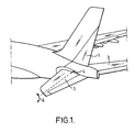
- Figure 1 illustrates the general configuration of the rear fuselage of an aircraft having trimmable horizontal stabilisers.
- the aircraft has a tail fin 1 which carries the aircraft rudder.
- Mounted horizontally on opposing sides of the rear fuselage are the horizontal stabilisers 3.
- Each horizontal stabiliser 3 is pivotably mounted to the fuselage at a pivot point 4, thus allowing each horizontal stabiliser to be pivoted about the pivot point 4 as indicated by the double headed arrow 5.
- the positioning of the horizontal stabilisers may be automatically controlled directly from the aircraft's flight control computers, or may be manually controlled from a pilot input command.
- the mechanism for causing the horizontal stabilisers 3 to move includes a ballscrew and ballnut.
- Figure 2 shows a ballnut 6 according to an embodiment of the present invention mounted on a ballscrew 8.
- the ballnut 6 actually comprises two nuts, a primary ballnut 10 and a secondary load path nut generally indicated 12.
- the primary ballnut 10 is connected to the horizontal stabiliser 3 by means of a known arrangement of connecting elements.
- a strut (not shown) pivotally attaches to a spherical bearing of a gimball 13 formed as in integral part of the primary ballnut 10.
- a similar gimball is formed on the other side of the device.
- Both the primary ballnut 10 and the secondary load path nut 12 have an internal thread that corresponds to the thread formed on the ballscrew 8.
- rotation of the ballscrew 8 driven by a known motor mechanism, causes linear translation of the ballnut assembly 6 along the ballscrew 8.
- the aerodynamic load exerted on the horizontal stabilisers is transmitted to the primary ballnut 10 via gimball 13.
- a side plate 14 has an aperture 14a that surrounds the gimball 13.
- the side plate is connected to the body of the secondary load path nut 12 via load bearing members 15.
- the side plate 14 and members 15 constitute a secondary load path which comes into effect in the event of failure of the gimball 13.
- FIG. 3 A cross-sectional diagram of the ballnut and ballscrew of Figure 2 is shown in Figure 3.
- the primary ballnut 10 is coupled to the primary load path via gimball 13.
- the secondary load path nut 12 itself comprises of two parts.
- the first part referred to herein as a secondary load path load bearing nut 20, is configured with a mounting flange (not shown on Figure 3) that is connected to the primary ballnut 10 by bolts.
- the second part referred to herein as the locking nut 24, is coupled to the secondary load path nut 20 by an integral bearing race 26 and a shear pin 28.
- a female thread form, matching that of the ballscrew shaft, is produced in both parts.
- the secondary load path nut 12 is configured such that the running clearance in the thread of the locking nut 24 is less than the running clearance in the secondary load path load bearing nut 20.
- Figure 4 shows a partial cross-section of the ballscrew 8, the primary load path nut 10 and the secondary load path nut 12 under normal conditions.
- the primary load path being indicated by the chain line 30 in Figure 4
- rotation of the ballscrew 8 will cause the primary load path nut 10 to translate.
- the secondary load path nut 12, being attached to the primary load path ballnut 10 will move in unison.
- the female thread of the secondary load path load bearing nut 20 and locking nut 24 do not contact the ballscrew under these conditions.
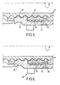
- Figures 5 illustrates the clearances 21 and 22 between the screw threads of the secondary load path load bearing nut 20 and locking nut 24, respectively, and the ballscrew 8.
- the clearance between the locking nut 24 and the thread of the ballscrew 8, indicated 22 in Figure 5 is less than the clearance between the thread of the secondary load path load bearing nut 20 and the ballscrew thread, shown as reference numeral 21.
- Figure 6 shows the arrangement of the secondary load path load bearing nut 20 and locking nut 24 immediately following a failure in the primary load path nut 10, by, for example, loss of ball bearings from the primary load path nut 10.
- load is transferred from the gimball 13, and via the body of the primary nut 10, to the secondary load path.
- the locking nut 24 Upon loading of the secondary load path the locking nut 24 is preferentially driven into engagement with the thread of the ballscrew 8.
- the locking nut 24 directly contacts the ballscrew 8 via frictional engagement between their respective surfaces.
- the locking nut 24 is also held with respect to the secondary load path load bearing nut 20 via low friction bearings 26.
- the shear pin 28 is dimensioned to withstand a small shear load, for example in the order of 100-600 Nm, to avoid unwanted accidental fracturing of the shear pin.
- load from the aircraft strut (not shown) is transferred immediately to the end plate 14, and from there via elements 15 to the body of the secondary load path nut 20 via gimball 25 (Figure 6).
- the interconnection between the secondary load path nut 20 and the primary load path nut 10 allows for a small amount of relative motion there between.
- the interconnection allowing a small amount of axial motion under load can be formed via the upstanding elements 50 and plates 52 ( Figure 3). Relative rotation between the primary locknut and the secondary locknut is prevented by splined interengagement between the nuts, shown generally in region 54 of Figure 3.
- the transfer of load to the secondary load path nut, and the nature of the interconnection between it and the primary load path nut, allows the secondary load path load bearing nut 20 and locking nut 24 to move slightly with respect to the primary load path nut 10, thereby removing the clearance between the helical thread of the locking nut 24, and the thread of the ballscrew 8.
- This in turn allows the locking nut 24 to frictionally engage with the ballscrew 8 such than an attempt to rotate the ballscrew 8 urges the locking nut 24 to rotate with the thread of the ballscrew 8.
- This in turn causes the sheer pin 28 to fail and a load loop is set up involving the shaft of the ballscrew 8, the secondary load path load bearing nut 20, the bearings 26, and the locking nut 24.
- the load path loop is such that an attempt to rotate the shaft 8 causes the locking nut 24 to try and move out of synchronisation with respect to the secondary load path load bearing nut 20, thereby increasing the frictional forces between each of them with respect to each other and the ballscrew 8. This again causes the motion of the ballscrew 8 to become stalled thereby locking the horizontal stabilisers in position.
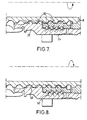
- Figure 7 shows the relative positions of the secondary load path load bearing nut 20 and locknut 24 after an attempt to rotate the ballscrew shaft 8 in one direction (clockwise).
- Figure 8 shows, by way of comparison, the relative positions after an attempt has been made to rotate the shaft in the opposite direction (anticlockwise).
Landscapes
- Engineering & Computer Science (AREA)
- General Engineering & Computer Science (AREA)
- Mechanical Engineering (AREA)
- Aviation & Aerospace Engineering (AREA)
- Transmission Devices (AREA)
Applications Claiming Priority (4)
| Application Number | Priority Date | Filing Date | Title |
|---|---|---|---|
| GB0119444 | 2001-08-09 | ||
| GB0119444A GB0119444D0 (en) | 2001-08-09 | 2001-08-09 | Ballscrew locking nut |
| GB0122832 | 2001-09-21 | ||
| GB0122832A GB2378494B (en) | 2001-08-09 | 2001-09-21 | Ballscrew locking nut |
Publications (2)
| Publication Number | Publication Date |
|---|---|
| EP1283384A2 true EP1283384A2 (de) | 2003-02-12 |
| EP1283384A3 EP1283384A3 (de) | 2004-08-11 |
Family
ID=26246420
Family Applications (1)
| Application Number | Title | Priority Date | Filing Date |
|---|---|---|---|
| EP02255432A Withdrawn EP1283384A3 (de) | 2001-08-09 | 2002-08-02 | Sicherungsmutter für eine Kugelumlaufspindel |
Country Status (2)
| Country | Link |
|---|---|
| US (1) | US6928895B2 (de) |
| EP (1) | EP1283384A3 (de) |
Cited By (13)
| Publication number | Priority date | Publication date | Assignee | Title |
|---|---|---|---|---|
| FR2844326A1 (fr) * | 2002-09-11 | 2004-03-12 | Trw Sys Aeronautiques Civil | Verin a vis a moyen de blocage en cas de passage sur ecrou secondaire |
| EP1262688A3 (de) * | 2001-05-30 | 2004-08-04 | Goodrich Actuation Systems Ltd | Spindelantrieb |
| FR2865254A1 (fr) * | 2004-01-21 | 2005-07-22 | Goodrich Actuation Systems | Dispositif de detection de transfert de charge par cisaillement d'un pion ruptible |
| EP1467124A3 (de) * | 2003-04-11 | 2006-06-07 | Umbra Cuscinetti S.p.A. | Kugelspindelantrieb für Flugzeugsteuerflächen |
| EP2256372A1 (de) * | 2009-05-25 | 2010-12-01 | Liebherr-Aerospace Lindenberg GmbH | Spindeltrieb |
| FR2970464A1 (fr) * | 2011-01-19 | 2012-07-20 | Goodrich Actuation Systems Sas | Perfectionnements aux actionneurs de commande de vol a ecrou secondaire |
| RU2524810C2 (ru) * | 2009-05-25 | 2014-08-10 | Либхерр-Аэроспейс Линденберг Гмбх | Привод ходового винта |
| FR3016607A1 (fr) * | 2014-01-20 | 2015-07-24 | Sagem Defense Securite | Actionneur de commande d'un plan horizontal de stabilisation d'un aeronef |
| WO2017125890A1 (en) * | 2016-01-20 | 2017-07-27 | Eaton Corporation | Ball screw with secondary lead for failure detection |
| EP3403925A1 (de) * | 2017-05-19 | 2018-11-21 | Goodrich Actuation Systems SAS | Unteres befestigungssystem für ein trimmbares horizontales stabilisatorstellglied |
| EP3789294A1 (de) * | 2019-09-04 | 2021-03-10 | Goodrich Actuation Systems SAS | Aktuator |
| EP4095415A1 (de) * | 2021-05-24 | 2022-11-30 | Goodrich Actuation Systems Limited | Kugelgewindeanordnung |
| EP4145018A1 (de) * | 2021-09-02 | 2023-03-08 | Goodrich Actuation Systems Limited | Leitspindelanordnung |
Families Citing this family (27)
| Publication number | Priority date | Publication date | Assignee | Title |
|---|---|---|---|---|
| FR2844325B1 (fr) * | 2002-09-11 | 2004-11-19 | Trw Sys Aeronautiques Civil | Detection par pion electrifie de transfert de charge sur ecrou secondaire dans un verin a vis |
| US7299703B2 (en) * | 2004-09-24 | 2007-11-27 | Balasu Mircea G | Bearing balls escape and wear annunciator arrangement for ball screw |
| TW200630337A (en) | 2004-10-14 | 2006-09-01 | Euro Celtique Sa | Piperidinyl compounds and the use thereof |
| DE602005008923D1 (de) * | 2005-06-09 | 2008-09-25 | Claverham Ltd | Elektro-mechanischer Lineartrieb |
| CN100575235C (zh) * | 2005-10-08 | 2009-12-30 | 上银科技股份有限公司 | 电梯的滚珠螺杆传动机构 |
| DE102005048394B3 (de) * | 2005-10-10 | 2007-02-15 | Siemens Ag | Spindelantrieb für Diagnose- oder Therapie-Einrichtung |
| US7610828B2 (en) * | 2005-11-15 | 2009-11-03 | Honeywell International Inc. | Flight control surface actuator assembly including a free trial mechanism |
| US20070170007A1 (en) * | 2005-11-22 | 2007-07-26 | Hiwin Technologies Corp. | Ball screw drive mechanism for an elevator |
| US8545178B2 (en) * | 2006-03-08 | 2013-10-01 | Hamilton Sundstrand Corporation | Controlled propeller pitch lock actuation system |
| US8267656B2 (en) * | 2006-03-08 | 2012-09-18 | Hamilton Sundstrand Corporation | Propeller pitch lock system |
| US8791264B2 (en) * | 2006-04-13 | 2014-07-29 | Purdue Pharma L.P. | Benzenesulfonamide compounds and their use as blockers of calcium channels |
| US20080203223A1 (en) * | 2006-06-22 | 2008-08-28 | Cyrot Luc P | Aircraft stabilizer actuator |
| FR2916023B1 (fr) * | 2007-05-11 | 2009-08-21 | Goodrich Actuation Systems Sas | Liaison mecanique fusible entre deux ecrous sur un ensemble a vis de securite a defaillance. |
| US8960031B2 (en) * | 2009-09-01 | 2015-02-24 | Parker-Hannifin Corporation | Aircraft stabilizer actuator |
| US9062748B1 (en) | 2009-09-30 | 2015-06-23 | David B. Guglietti | Ball screw nut |
| US9279487B1 (en) | 2009-09-30 | 2016-03-08 | David B. Guglietti | Ball screw and parts |
| DE102009045857A1 (de) * | 2009-10-20 | 2011-04-21 | Robert Bosch Gmbh | Verfahren zur Herstellung einer Spindel für einen Spindeltrieb, Wälzgewindetrieb mit einer solchen Spindel und Verwendung des Wälzgewindetriebs |
| US9086035B2 (en) * | 2012-01-20 | 2015-07-21 | Hamilton Sundstrand Corporation | Integrated thrust reverser actuator and variable area fan nozzle actuator |
| JP6148961B2 (ja) * | 2013-10-08 | 2017-06-14 | ナブテスコ株式会社 | 電動アクチュエータ |
| EP3072809B1 (de) | 2015-03-27 | 2020-07-15 | Goodrich Actuation Systems SAS | Untere befestigung für einen trimmbaren horizontalen stabilisatoraktuator |
| FR3044635B1 (fr) * | 2015-12-04 | 2018-08-17 | Ratier Figeac | Butee d'absorption d'energie de fin de course d'actionneur d'aeronef a portee destructible demontable, actionneur et aeronef |
| DE102016223978A1 (de) | 2016-12-01 | 2018-06-07 | Schaeffler Technologies AG & Co. KG | Spindeltrieb mit Arretierung |
| US10974846B2 (en) * | 2016-12-09 | 2021-04-13 | Parker-Hannifin Corporation | Fixed end electronic detection of secondary load path engagement of aircraft flight control actuator |
| EP3757003B1 (de) * | 2019-06-25 | 2021-08-11 | LEONARDO S.p.A. | Drehmomentausgleichsrotor für einen hubschrauber |
| CN111981098B (zh) * | 2020-08-17 | 2022-07-15 | 西北工业大学 | 一种可自锁且有效行程无级可调的机电作动器 |
| US11867263B2 (en) | 2022-05-04 | 2024-01-09 | Halliburton Energy Services, Inc. | Linear actuators, motor assemblies, and methods to actuate a device or load |
| CN115654092B (zh) * | 2022-09-07 | 2026-04-03 | 普勒宇传动科技(浙江)有限公司 | 一种具有逆向止动的滚珠丝杠传动 |
Family Cites Families (17)
| Publication number | Priority date | Publication date | Assignee | Title |
|---|---|---|---|---|
| GB112984A (en) * | 1917-02-01 | 1918-02-01 | Antoine Mouneyrat | Improvements in or relating to the Preparation of Aqueous Solutions of Arsenobenzene Derivatives Containing the Arseno Group (-As=As-) in their Molecule. |
| US3766790A (en) * | 1971-12-29 | 1973-10-23 | Boeing Co | Non-jamming ball screw linear actuator |
| US4603594A (en) * | 1984-05-31 | 1986-08-05 | Sundstrand Corporation | Fail safe actuator |
| US4679485A (en) * | 1984-12-27 | 1987-07-14 | Sundstrand Corporation | Ballistic tolerant dual load path ballscrew and ballscrew actuator |
| US4644811A (en) * | 1985-06-19 | 1987-02-24 | The United States Of America As Represented By The Secretary Of The Air Force | Termination load carrying device |
| US4637272A (en) * | 1985-10-28 | 1987-01-20 | Sundstrand Corporation | Ballscrew actuator |
| US4745815A (en) * | 1986-12-08 | 1988-05-24 | Sundstrand Corporation | Non-jamming screw actuator system |
| US5144851A (en) * | 1991-08-01 | 1992-09-08 | Sundstrand Corp. | Jam tolerant linear actuator |
| US5313852A (en) * | 1992-11-06 | 1994-05-24 | Grumman Aerospace Corporation | Differential linear actuator |
| EP0722546B1 (de) | 1993-10-15 | 1998-04-22 | Skf Specialty Products Ab | Fallsicherung für linearantriebe |
| DE29816790U1 (de) | 1998-09-18 | 1998-11-19 | Dewert Antriebs- und Systemtechnik GmbH & Co KG, 32278 Kirchlengern | Elektromotorischer Linearantrieb |
| JP3349098B2 (ja) * | 1998-09-18 | 2002-11-20 | 株式会社椿本チエイン | 落下防止機構付直線作動機 |
| US6389915B1 (en) * | 1999-05-17 | 2002-05-21 | Alliedsignal, Inc. | Dual load path ball screw with rod end swivel |
| DE20008048U1 (de) | 2000-05-04 | 2000-08-17 | Hiwin Mikrosystem Corp., Taichung | Schraubspindelmechanismus |
| US6467363B2 (en) * | 2001-02-07 | 2002-10-22 | Moog Inc. | Ball screw actuator locking mechanism |
| GB0112984D0 (en) * | 2001-05-30 | 2001-07-18 | Lucas Industries Ltd | Screw actuator |
| FR2844326B1 (fr) * | 2002-09-11 | 2005-05-13 | Trw Sys Aeronautiques Civil | Verin a vis a moyen de blocage en cas de passage sur ecrou secondaire |
-
2002
- 2002-08-02 EP EP02255432A patent/EP1283384A3/de not_active Withdrawn
- 2002-08-06 US US10/214,246 patent/US6928895B2/en not_active Expired - Fee Related
Non-Patent Citations (1)
| Title |
|---|
| None |
Cited By (28)
| Publication number | Priority date | Publication date | Assignee | Title |
|---|---|---|---|---|
| EP1262688A3 (de) * | 2001-05-30 | 2004-08-04 | Goodrich Actuation Systems Ltd | Spindelantrieb |
| FR2844326A1 (fr) * | 2002-09-11 | 2004-03-12 | Trw Sys Aeronautiques Civil | Verin a vis a moyen de blocage en cas de passage sur ecrou secondaire |
| EP1398541A1 (de) * | 2002-09-11 | 2004-03-17 | Goodrich Actuation Systems | Spindelantrieb mit klemmender Vorrichtung beim belasten der zweiten Mutter |
| EP1467124A3 (de) * | 2003-04-11 | 2006-06-07 | Umbra Cuscinetti S.p.A. | Kugelspindelantrieb für Flugzeugsteuerflächen |
| FR2865254A1 (fr) * | 2004-01-21 | 2005-07-22 | Goodrich Actuation Systems | Dispositif de detection de transfert de charge par cisaillement d'un pion ruptible |
| EP1557588A1 (de) * | 2004-01-21 | 2005-07-27 | Goodrich Actuation Systems SAS | Detektionvorrichtung zur Lastübertragung mit einem Scherstift |
| EP2256372A1 (de) * | 2009-05-25 | 2010-12-01 | Liebherr-Aerospace Lindenberg GmbH | Spindeltrieb |
| US8656797B2 (en) | 2009-05-25 | 2014-02-25 | Liebherr-Aerospace Lindenberg Gmbh | Spindle drive |
| RU2524255C2 (ru) * | 2009-05-25 | 2014-07-27 | Либхерр-Аэроспейс Линденберг Гмбх | Привод ходового винта |
| RU2524810C2 (ru) * | 2009-05-25 | 2014-08-10 | Либхерр-Аэроспейс Линденберг Гмбх | Привод ходового винта |
| FR2970464A1 (fr) * | 2011-01-19 | 2012-07-20 | Goodrich Actuation Systems Sas | Perfectionnements aux actionneurs de commande de vol a ecrou secondaire |
| WO2012098206A1 (fr) * | 2011-01-19 | 2012-07-26 | Goodrich Actuation Systems Sas | Perfectionnements aux actionneurs de commande de vol a ecrou secondaire |
| CN106458315A (zh) * | 2014-01-20 | 2017-02-22 | 赛峰电子与防务公司 | 用于对飞行器的水平稳定器进行控制的致动器 |
| WO2015107208A3 (fr) * | 2014-01-20 | 2015-09-11 | Sagem Defense Securite | Actionneur de commande d'un plan horizontal de stabilisation d'un aeronef |
| FR3016607A1 (fr) * | 2014-01-20 | 2015-07-24 | Sagem Defense Securite | Actionneur de commande d'un plan horizontal de stabilisation d'un aeronef |
| CN106458315B (zh) * | 2014-01-20 | 2018-02-02 | 赛峰电子与防务公司 | 用于对飞行器的水平稳定器进行控制的致动器 |
| US10040539B2 (en) | 2014-01-20 | 2018-08-07 | Safran Electronics And Defense | Actuator for controlling a horizontal stabilizer of an aircraft |
| WO2017125890A1 (en) * | 2016-01-20 | 2017-07-27 | Eaton Corporation | Ball screw with secondary lead for failure detection |
| US11149828B2 (en) | 2016-01-20 | 2021-10-19 | Eaton Intelligent Power Limited | Ball screw with secondary lead for failure detection |
| US10800515B2 (en) | 2017-05-19 | 2020-10-13 | Goodrich Actuation Systems Sas | Lower attachment system for a trimmable horizontal stabiliser actuator |
| EP3403925A1 (de) * | 2017-05-19 | 2018-11-21 | Goodrich Actuation Systems SAS | Unteres befestigungssystem für ein trimmbares horizontales stabilisatorstellglied |
| RU2758840C2 (ru) * | 2017-05-19 | 2021-11-02 | Гудрич Актюасьён Системз Сас | Система нижнего крепления для привода управляемого горизонтального стабилизатора |
| EP3789294A1 (de) * | 2019-09-04 | 2021-03-10 | Goodrich Actuation Systems SAS | Aktuator |
| US11287019B2 (en) | 2019-09-04 | 2022-03-29 | Goodrich Actuation Systems Sas | Actuator |
| EP4095415A1 (de) * | 2021-05-24 | 2022-11-30 | Goodrich Actuation Systems Limited | Kugelgewindeanordnung |
| US11703111B2 (en) | 2021-05-24 | 2023-07-18 | Goodrich Actuation Systems Limited | Ball screw assembly |
| EP4145018A1 (de) * | 2021-09-02 | 2023-03-08 | Goodrich Actuation Systems Limited | Leitspindelanordnung |
| US11953081B2 (en) | 2021-09-02 | 2024-04-09 | Goodrich Actuation Systems Limited | Lead screw assembly |
Also Published As
| Publication number | Publication date |
|---|---|
| US6928895B2 (en) | 2005-08-16 |
| EP1283384A3 (de) | 2004-08-11 |
| US20030029258A1 (en) | 2003-02-13 |
Similar Documents
| Publication | Publication Date | Title |
|---|---|---|
| US6928895B2 (en) | Ballscrew locking nut | |
| US11209074B2 (en) | Lower attachment for trimmable horizontal stabiliser actuator | |
| US8291782B1 (en) | Actuator assembly for stabilizers | |
| US6851648B2 (en) | Ball screw actuator for aircraft control surfaces | |
| US8118254B2 (en) | Flap actuator | |
| US8393568B2 (en) | Enhanced lubrication skewed roller clutch assembly and actuator including same | |
| CN112081891B (zh) | 致动器下部附接件 | |
| RU2733559C1 (ru) | Силовой привод | |
| WO1990009314A1 (en) | Multi-fuseable shaft | |
| US8714479B1 (en) | Centering, release and reset mechanism | |
| EP3127805B1 (de) | Untere befestigung für einen trimmbaren horizontalen stabilisatoraktuator | |
| US12540659B2 (en) | Screw actuators | |
| GB2378494A (en) | Ballscrew locking nut | |
| EP4461993A1 (de) | Trimmbarer sekundärlastpfaddetektor für horizontalen stabilisatoraktuator | |
| EP4311768B1 (de) | Spoileraktuator | |
| BR102019026502B1 (pt) | Atuador de parafuso, e, aeronave | |
| US20220194574A1 (en) | Tail rotor actuator joint |
Legal Events
| Date | Code | Title | Description |
|---|---|---|---|
| PUAI | Public reference made under article 153(3) epc to a published international application that has entered the european phase |
Free format text: ORIGINAL CODE: 0009012 |
|
| AK | Designated contracting states |
Designated state(s): AT BE BG CH CY CZ DE DK EE ES FI FR GB GR IE IT LI LU MC NL PT SE SK TR |
|
| AX | Request for extension of the european patent |
Extension state: AL LT LV MK RO SI |
|
| PUAL | Search report despatched |
Free format text: ORIGINAL CODE: 0009013 |
|
| RIC1 | Information provided on ipc code assigned before grant |
Ipc: 7B 64C 9/02 B Ipc: 7F 16H 25/24 B Ipc: 7F 16H 25/22 A |
|
| AK | Designated contracting states |
Kind code of ref document: A3 Designated state(s): AT BE BG CH CY CZ DE DK EE ES FI FR GB GR IE IT LI LU MC NL PT SE SK TR |
|
| AX | Request for extension of the european patent |
Extension state: AL LT LV MK RO SI |
|
| 17P | Request for examination filed |
Effective date: 20050207 |
|
| AKX | Designation fees paid |
Designated state(s): AT BE BG CH CY CZ DE DK EE ES FI FR GB GR IE IT LI LU MC NL PT SE SK TR |
|
| GRAP | Despatch of communication of intention to grant a patent |
Free format text: ORIGINAL CODE: EPIDOSNIGR1 |
|
| STAA | Information on the status of an ep patent application or granted ep patent |
Free format text: STATUS: THE APPLICATION IS DEEMED TO BE WITHDRAWN |
|
| 18D | Application deemed to be withdrawn |
Effective date: 20061124 |