EP1283163B1 - Vorrichtung zur Verringerung des strömungsmechanischen Reibungswiderstandes - Google Patents
Vorrichtung zur Verringerung des strömungsmechanischen Reibungswiderstandes Download PDFInfo
- Publication number
- EP1283163B1 EP1283163B1 EP02017177A EP02017177A EP1283163B1 EP 1283163 B1 EP1283163 B1 EP 1283163B1 EP 02017177 A EP02017177 A EP 02017177A EP 02017177 A EP02017177 A EP 02017177A EP 1283163 B1 EP1283163 B1 EP 1283163B1
- Authority
- EP
- European Patent Office
- Prior art keywords
- flow
- ribs
- riblets
- rib
- component
- Prior art date
- Legal status (The legal status is an assumption and is not a legal conclusion. Google has not performed a legal analysis and makes no representation as to the accuracy of the status listed.)
- Expired - Lifetime
Links
- 239000012530 fluid Substances 0.000 description 2
- 239000002245 particle Substances 0.000 description 2
- 230000001914 calming effect Effects 0.000 description 1
- 239000002131 composite material Substances 0.000 description 1
- 238000005516 engineering process Methods 0.000 description 1
- 239000000284 extract Substances 0.000 description 1
- 238000000605 extraction Methods 0.000 description 1
- 239000000835 fiber Substances 0.000 description 1
- 239000000446 fuel Substances 0.000 description 1
- 230000003993 interaction Effects 0.000 description 1
- 238000007493 shaping process Methods 0.000 description 1
- 238000004381 surface treatment Methods 0.000 description 1
- 238000004804 winding Methods 0.000 description 1
Images


Classifications
-
- F—MECHANICAL ENGINEERING; LIGHTING; HEATING; WEAPONS; BLASTING
- F15—FLUID-PRESSURE ACTUATORS; HYDRAULICS OR PNEUMATICS IN GENERAL
- F15D—FLUID DYNAMICS, i.e. METHODS OR MEANS FOR INFLUENCING THE FLOW OF GASES OR LIQUIDS
- F15D1/00—Influencing flow of fluids
- F15D1/10—Influencing flow of fluids around bodies of solid material
- F15D1/12—Influencing flow of fluids around bodies of solid material by influencing the boundary layer
-
- B—PERFORMING OPERATIONS; TRANSPORTING
- B64—AIRCRAFT; AVIATION; COSMONAUTICS
- B64C—AEROPLANES; HELICOPTERS
- B64C21/00—Influencing air flow over aircraft surfaces by affecting boundary layer flow
- B64C21/10—Influencing air flow over aircraft surfaces by affecting boundary layer flow using other surface properties, e.g. roughness
-
- F—MECHANICAL ENGINEERING; LIGHTING; HEATING; WEAPONS; BLASTING
- F15—FLUID-PRESSURE ACTUATORS; HYDRAULICS OR PNEUMATICS IN GENERAL
- F15D—FLUID DYNAMICS, i.e. METHODS OR MEANS FOR INFLUENCING THE FLOW OF GASES OR LIQUIDS
- F15D1/00—Influencing flow of fluids
- F15D1/002—Influencing flow of fluids by influencing the boundary layer
- F15D1/0025—Influencing flow of fluids by influencing the boundary layer using passive means, i.e. without external energy supply
- F15D1/003—Influencing flow of fluids by influencing the boundary layer using passive means, i.e. without external energy supply comprising surface features, e.g. indentations or protrusions
- F15D1/0035—Influencing flow of fluids by influencing the boundary layer using passive means, i.e. without external energy supply comprising surface features, e.g. indentations or protrusions in the form of riblets
- F15D1/0045—Influencing flow of fluids by influencing the boundary layer using passive means, i.e. without external energy supply comprising surface features, e.g. indentations or protrusions in the form of riblets oriented essentially perpendicular to the direction of flow
-
- Y—GENERAL TAGGING OF NEW TECHNOLOGICAL DEVELOPMENTS; GENERAL TAGGING OF CROSS-SECTIONAL TECHNOLOGIES SPANNING OVER SEVERAL SECTIONS OF THE IPC; TECHNICAL SUBJECTS COVERED BY FORMER USPC CROSS-REFERENCE ART COLLECTIONS [XRACs] AND DIGESTS
- Y02—TECHNOLOGIES OR APPLICATIONS FOR MITIGATION OR ADAPTATION AGAINST CLIMATE CHANGE
- Y02T—CLIMATE CHANGE MITIGATION TECHNOLOGIES RELATED TO TRANSPORTATION
- Y02T50/00—Aeronautics or air transport
- Y02T50/10—Drag reduction
Definitions
- the invention relates to a device for Reduction of fluid mechanics Friction resistance in one of one Flow medium flowed around component, in particular for an airplane, with one on the surface around it the component arranged fine rib configuration, their contour lines perpendicular to the flow direction stand and where the cross section of the ribs in Flow direction has a sawtooth shape.
- Friction resistance of modern commercial aircraft is about 50% of the total resistance and thus also causes 50% of the fuel consumption.
- Technical solutions for the reduction of Friction resistance is aimed at increasing the Laminarity and a calming of the turbulence of the Flow, z. B. by turbulence management means Riblets, from or on a hybrid laminarization by appropriate extraction.
- DE 35 34 293 C2 is a device for Reduction of fluid mechanics Friction resistance in aircraft and spacecraft as well watercraft with one Grooved surface configuration described as integral groove surface directly from one Fiber composite material to be produced Support structure of the vehicle is formed.
- the integral groove surface by shaping at the Laying, surface treatment or winding technology of be formed to be formed support structure.
- the invention is based on the object, a Device of the type mentioned in such a way to train that the largest possible reduction of fluid-mechanical frictional resistance at a flow around the surface of a component is achieved.
- a particular advantage of the invention is that by the structuring provided according to the invention the surface primarily not the flow boundary layer itself, but directly the interaction between the Particles of the circulating medium and the flow around Surface is influenced in such a way that of the Particles of the flow transferred to the surface Tangential pulse is reduced.
- Embodiments of the invention are in the other Claims 2 to 4 described.
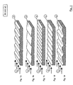
- the direction of the Components circulating flow designated 1, and it are all ribs of the rib configurations or their Contour lines perpendicular to this flow direction. 1 arranged.
- the Cross-section of the ribs according to FIG. 1b according to the invention has a Sawtooth shape with a steep flank rise and a each flat drop of flanks in the flow direction.
- Fig. 2 are flowed around on one of a flow Component three in the flow direction 1 extending Arranged strips 7, each having an arrangement of Having ribs in the flow direction 1. Ribs adjacent strips 7 and their ridges are out of phase with each other. However, that is in the Here illustrated example, the flow direction opposite represented to the claimed direction.
- Fig. 3 is perpendicular to the flow direction.
- the cross sections of the Riblets 8 can be seen from the section A-A, wherein the top edge of the riblets 8 as a straight line is formed, as can be seen from the section B-B is.
- rib configuration with Ribs 10, which also flowed around in one Component existing, in the flow direction. 1 extending riblets 8 is arranged differs from that shown in Fig. 3 Rib configurations with associated ribs 9 thereby that the respective uppermost edge of the riblets 8 the Cross-section of the rib configuration corresponds. This is shown in section B-B of Fig. 4.
Landscapes
- Engineering & Computer Science (AREA)
- Physics & Mathematics (AREA)
- Fluid Mechanics (AREA)
- Mechanical Engineering (AREA)
- General Engineering & Computer Science (AREA)
- Aviation & Aerospace Engineering (AREA)
- Structures Of Non-Positive Displacement Pumps (AREA)
- Extrusion Moulding Of Plastics Or The Like (AREA)
- Cable Accessories (AREA)
- Multiple-Way Valves (AREA)
- Adjustment Of The Magnetic Head Position Track Following On Tapes (AREA)
- Sliding-Contact Bearings (AREA)
Description
- Fig. 1
- die Rippenkonfigurationen der Oberfläche eines umströmten Bauteiles auszugsweise in perspektivischer Seitenansicht;
- Fig. 2
- die Ausführungsform von in Strömungsrichtung phasenversetzten Streifen mit Rippenkonfigurationen der Oberfläche eines umströmten Bauteiles auszugsweise in perspektivischer Seitenansicht;
- Fig. 3
- die Ausführungsform einer Rippenkonfiguration auf der Oberfläche von Riblets in Dreiseitenansicht, bei der die Höhe der Riblets unverändert bleibt; und
- Fig. 4
- die Ausführungsform einer Rippenkonfiguration auf der Oberfläche von Riblets in Dreiseitenansicht, bei der die Höhe der Riblets sich mit der Rippenkonfiguration ändert.
Claims (4)
- Vorrichtung zur Verringerung des strömungsmechanischen Reibungswiderstandes bei einem von einem Strömungsmedium umströmten Bauteil, insbesondere für ein Flugzeug, mit einer auf der umströmten Oberfläche des Bauteiles angeordneten feinen Rippenkonfiguration, deren Höhenlinien senkrecht zur Strömungsrichtung stehen und wobei der Querschnitt der Rippen in Strömungsrichtung eine Sägezahnform aufweist, dadurch gekennzeichnet, daß in Strömungsrichtung (1) die Sägezahnform der Rippen (3) einen steilen Flankenanstieg und einen jeweils flachen Abfall der Flanken aufweist.
- Vorrichtung nach Anspruch 1, dadurch gekennzeichnet, daß die Rippen (3) in Strömungsrichtung (1) in einzelnen parallel zur Strömungsrichtung (1) verlaufenden Streifen (7) angeordnet sind und daß die Rippen (3) benachbarter Streifen (7) phasenversetzt zueinander angeordnet sind.
- Vorrichtung nach Anspruch 1, dadurch gekennzeichnet, daß die Rippenkonfiguration mit den zugehörigen Rippen (3) in vorhandenen, in Strömungsrichtung verlaufenden Riblets (8) angeordnet ist und daß die jeweils oberste Kante der Riblets (8) als gerade Linie ausgebildet ist.
- Vorrichtung nach Anspruch 1, dadurch gekennzeichnet, daß die Rippenkonfiguration mit den zugehörigen Rippen (3) in vorhandenen, in Strömungsrichtung verlaufenden Riblets (8) angeordnet ist und daß die jeweils oberste Kante der Riblets (8) dem Querschnitt der Rippenkonfiguration entspricht.
Applications Claiming Priority (2)
| Application Number | Priority Date | Filing Date | Title |
|---|---|---|---|
| DE10139436A DE10139436A1 (de) | 2001-08-10 | 2001-08-10 | Vorrichtung zur Verringerung des strömungsmechanischen Reibungswiderstandes |
| DE10139436 | 2001-08-10 |
Publications (3)
| Publication Number | Publication Date |
|---|---|
| EP1283163A2 EP1283163A2 (de) | 2003-02-12 |
| EP1283163A3 EP1283163A3 (de) | 2003-06-11 |
| EP1283163B1 true EP1283163B1 (de) | 2005-05-04 |
Family
ID=7695102
Family Applications (1)
| Application Number | Title | Priority Date | Filing Date |
|---|---|---|---|
| EP02017177A Expired - Lifetime EP1283163B1 (de) | 2001-08-10 | 2002-07-31 | Vorrichtung zur Verringerung des strömungsmechanischen Reibungswiderstandes |
Country Status (3)
| Country | Link |
|---|---|
| EP (1) | EP1283163B1 (de) |
| AT (1) | ATE294731T1 (de) |
| DE (2) | DE10139436A1 (de) |
Cited By (1)
| Publication number | Priority date | Publication date | Assignee | Title |
|---|---|---|---|---|
| EP4733604A1 (de) | 2024-09-30 | 2026-04-29 | Politechnika Czestochowska | Gewellter beschichtung und verfahren zur auswahl der beschichtungsparameter |
Families Citing this family (13)
| Publication number | Priority date | Publication date | Assignee | Title |
|---|---|---|---|---|
| US20060068109A1 (en) | 2004-09-15 | 2006-03-30 | Airbus Deutschland Gmbh | Painting device, painting arrangement, method for painting a curved surface of an object, and use of an inkjet device for painting an aircraft |
| DE102004044655B4 (de) * | 2004-09-15 | 2009-06-10 | Airbus Deutschland Gmbh | Lackier-Vorrichtung, Lackier-Anordnung, Verfahren zum Lackieren einer gekrümmten Oberfläche eines Flugzeugs und Verwendung einer Inkjet-Einrichtung zum Lackieren eines Flugzeugs |
| NL1032739C2 (nl) * | 2006-10-24 | 2008-04-25 | Kick Off Ltd | Object met oppervlak voor het genereren van microwervels. |
| DE102007026118B4 (de) | 2007-06-05 | 2010-12-16 | Kägi, Adrian | Von einem Medium umströmter, Bugwellen und/oder Heckwellen bildender Körper mit einem stufenförmig ausgebildeten Bug und/oder Heck |
| NL1035216C2 (nl) * | 2007-07-24 | 2009-01-27 | Kick Off Ltd | Wrijvingsweerstand reducerende laag en werkwijze voor de vervaardiging daarvan. |
| ES2326356B1 (es) * | 2008-03-31 | 2010-07-13 | Maria Desamparados Segura Mecho | Elemento impulsor aerodinamico. |
| DE102012202996A1 (de) * | 2012-02-28 | 2013-08-29 | Marco Feusi | Wirbelstruktur für Windradflügel |
| DE102013013817A1 (de) * | 2013-08-22 | 2015-02-26 | Airbus Defence and Space GmbH | Strukturbauteil mit einer Ribletoberfläche |
| US9308987B1 (en) | 2014-05-15 | 2016-04-12 | The Curators Of The University Of Missouri | Drag reduction utilizing driven micro-cavities |
| DE102017201782B4 (de) | 2017-02-03 | 2024-08-14 | Lufthansa Technik Aktiengesellschaft | Riblet-Struktur |
| US20180244370A1 (en) * | 2017-02-18 | 2018-08-30 | Jean-Eloi William Lombard | Passive flow control mechanism for suppressing tollmien-schlichting waves, delaying transition to turbulence and reducing drag |
| US11618511B2 (en) * | 2021-01-12 | 2023-04-04 | Honda Motor Co., Ltd. | Surface pattern for a vehicle |
| CN117566095A (zh) * | 2023-11-24 | 2024-02-20 | 中国航空工业集团公司沈阳空气动力研究所 | 一种纵向变化的三维湍流减阻微肋条结构 |
Family Cites Families (5)
| Publication number | Priority date | Publication date | Assignee | Title |
|---|---|---|---|---|
| US4284302A (en) * | 1979-06-11 | 1981-08-18 | Drews Hilbert F P | Driven craft having surface means for increasing propulsion efficiencies |
| US4986496A (en) * | 1985-05-31 | 1991-01-22 | Minnesota Mining And Manufacturing | Drag reduction article |
| DE3534293A1 (de) * | 1985-09-26 | 1987-04-02 | Messerschmitt Boelkow Blohm | Einrichtung zur verringerung des reibungswiderstandes |
| US5133519A (en) * | 1989-04-21 | 1992-07-28 | Board Of Trustees Operating Michigan State University | Drag reduction method and surface |
| GB9207000D0 (en) * | 1992-03-31 | 1992-05-13 | Rolls Royce Plc | Control of fluid flow |
-
2001
- 2001-08-10 DE DE10139436A patent/DE10139436A1/de not_active Withdrawn
-
2002
- 2002-07-31 DE DE50202975T patent/DE50202975D1/de not_active Expired - Lifetime
- 2002-07-31 EP EP02017177A patent/EP1283163B1/de not_active Expired - Lifetime
- 2002-07-31 AT AT02017177T patent/ATE294731T1/de not_active IP Right Cessation
Cited By (1)
| Publication number | Priority date | Publication date | Assignee | Title |
|---|---|---|---|---|
| EP4733604A1 (de) | 2024-09-30 | 2026-04-29 | Politechnika Czestochowska | Gewellter beschichtung und verfahren zur auswahl der beschichtungsparameter |
Also Published As
| Publication number | Publication date |
|---|---|
| EP1283163A3 (de) | 2003-06-11 |
| ATE294731T1 (de) | 2005-05-15 |
| DE10139436A1 (de) | 2003-03-06 |
| EP1283163A2 (de) | 2003-02-12 |
| DE50202975D1 (de) | 2005-06-09 |
Similar Documents
| Publication | Publication Date | Title |
|---|---|---|
| EP1283163B1 (de) | Vorrichtung zur Verringerung des strömungsmechanischen Reibungswiderstandes | |
| DE19650439C1 (de) | Oberfläche für eine von einer eine Strömungshauptrichtung aufweisenden Strömung turbulent umströmten Wand | |
| DE19650439C9 (de) | Oberfläche für eine von einer eine Strömungshauptrichtung aufweisenden Strömung turbulent umströmten Wand | |
| DE3884826T2 (de) | Vorrichtung zum Verhindern der Verschmutzung von Motorfahrzeug-Heckleuchteneinheiten. | |
| DE4441592C2 (de) | Luftleiteinrichtung | |
| EP1149761A1 (de) | Einrichtung zur Lärmminderung an Tragflügeln von Flugzeugen | |
| DE3441554A1 (de) | Verminderten stroemungswiderstand aufweisende oberflaeche eines turbulent ueberstroemten koerpers | |
| DE102006008434A1 (de) | Vorrichtung zur Reduzierung des aerodynamisch bedingten Lärms an der Seitenkante einer Stellfläche, insbesondere einer Hochauftriebsfläche eines Flugzeugs | |
| EP2528810A1 (de) | Struktur zur verringerung eines strömungswiderstands eines körpers in einem fluid | |
| DE2738257C2 (de) | Vorrichtung zur Abscheidung von Tropfen aus strömenden Gasen | |
| DE102017129746B4 (de) | Luftleitmittel für ein Kraftfahrzeug | |
| WO2018138263A1 (de) | Hydrofoil für ein wasserfahrzeug | |
| DE102017201782A1 (de) | Riblet-Struktur | |
| DE69103600T2 (de) | Ventil mit verzahntem Sitz. | |
| DE10356172B4 (de) | Einrichtung aus Führungen und einem Gleitpaneel, und Sonnenblende zur Anwendung darin | |
| DE19631537C2 (de) | Grenzschichtprofil für Flüssigkeiten und/oder Gase | |
| DE2910871C2 (de) | Zahnriementrieb | |
| DE930724C (de) | Verfahren und Vorrichtung zur Verhinderung des Abloesens eines stroemenden Mediums von einem umstroemten Koerper | |
| DE4442319C1 (de) | Flügel für Anströmgeschwindigkeiten im hohen Unterschallbereich | |
| DE10007800A1 (de) | Wischblatt | |
| DE3779961T2 (de) | Grenzschichtdurchflussregelung. | |
| WO2011101062A1 (de) | Wischblatteinheit | |
| DE102020117405A1 (de) | Luftleitvorrichtung für eine Kraftfahrzeugkarosserie und Kraftfahrzeugkarosserie | |
| DE102012214734B3 (de) | Körper, Strömungskanal, Strahltriebwerk, Auftriebsvorrichtung oder Folie mit einer Struktur zur Verringerung eines Strömungswiderstands eines Körpers in einem Fluid | |
| DE102011079903A1 (de) | Struktur zur Verringerung eines Strömungswiderstands eines Körpers in einem Fluid |
Legal Events
| Date | Code | Title | Description |
|---|---|---|---|
| PUAI | Public reference made under article 153(3) epc to a published international application that has entered the european phase |
Free format text: ORIGINAL CODE: 0009012 |
|
| AK | Designated contracting states |
Designated state(s): AT BE BG CH CY CZ DE DK EE ES FI FR GB GR IE IT LI LU MC NL PT SE SK TR |
|
| AX | Request for extension of the european patent |
Extension state: AL LT LV MK RO SI |
|
| PUAL | Search report despatched |
Free format text: ORIGINAL CODE: 0009013 |
|
| AK | Designated contracting states |
Designated state(s): AT BE BG CH CY CZ DE DK EE ES FI FR GB GR IE IT LI LU MC NL PT SE SK TR |
|
| AX | Request for extension of the european patent |
Extension state: AL LT LV MK RO SI |
|
| 17P | Request for examination filed |
Effective date: 20031211 |
|
| AKX | Designation fees paid |
Designated state(s): AT BE BG CH CY CZ DE DK EE ES FI FR GB GR IE IT LI LU MC NL PT SE SK TR |
|
| 17Q | First examination report despatched |
Effective date: 20040213 |
|
| GRAP | Despatch of communication of intention to grant a patent |
Free format text: ORIGINAL CODE: EPIDOSNIGR1 |
|
| GRAS | Grant fee paid |
Free format text: ORIGINAL CODE: EPIDOSNIGR3 |
|
| GRAA | (expected) grant |
Free format text: ORIGINAL CODE: 0009210 |
|
| AK | Designated contracting states |
Kind code of ref document: B1 Designated state(s): AT BE BG CH CY CZ DE DK EE ES FI FR GB GR IE IT LI LU MC NL PT SE SK TR |
|
| PG25 | Lapsed in a contracting state [announced via postgrant information from national office to epo] |
Ref country code: SK Free format text: LAPSE BECAUSE OF FAILURE TO SUBMIT A TRANSLATION OF THE DESCRIPTION OR TO PAY THE FEE WITHIN THE PRESCRIBED TIME-LIMIT Effective date: 20050504 Ref country code: FI Free format text: LAPSE BECAUSE OF FAILURE TO SUBMIT A TRANSLATION OF THE DESCRIPTION OR TO PAY THE FEE WITHIN THE PRESCRIBED TIME-LIMIT Effective date: 20050504 Ref country code: ES Free format text: LAPSE BECAUSE OF FAILURE TO SUBMIT A TRANSLATION OF THE DESCRIPTION OR TO PAY THE FEE WITHIN THE PRESCRIBED TIME-LIMIT Effective date: 20050504 Ref country code: IE Free format text: LAPSE BECAUSE OF FAILURE TO SUBMIT A TRANSLATION OF THE DESCRIPTION OR TO PAY THE FEE WITHIN THE PRESCRIBED TIME-LIMIT Effective date: 20050504 Ref country code: EE Free format text: LAPSE BECAUSE OF FAILURE TO SUBMIT A TRANSLATION OF THE DESCRIPTION OR TO PAY THE FEE WITHIN THE PRESCRIBED TIME-LIMIT Effective date: 20050504 Ref country code: TR Free format text: LAPSE BECAUSE OF FAILURE TO SUBMIT A TRANSLATION OF THE DESCRIPTION OR TO PAY THE FEE WITHIN THE PRESCRIBED TIME-LIMIT Effective date: 20050504 Ref country code: CZ Free format text: LAPSE BECAUSE OF FAILURE TO SUBMIT A TRANSLATION OF THE DESCRIPTION OR TO PAY THE FEE WITHIN THE PRESCRIBED TIME-LIMIT Effective date: 20050504 |
|
| REG | Reference to a national code |
Ref country code: GB Ref legal event code: FG4D Free format text: NOT ENGLISH |
|
| REG | Reference to a national code |
Ref country code: CH Ref legal event code: EP |
|
| REG | Reference to a national code |
Ref country code: IE Ref legal event code: FG4D Free format text: LANGUAGE OF EP DOCUMENT: GERMAN |
|
| REF | Corresponds to: |
Ref document number: 50202975 Country of ref document: DE Date of ref document: 20050609 Kind code of ref document: P |
|
| PG25 | Lapsed in a contracting state [announced via postgrant information from national office to epo] |
Ref country code: CY Free format text: LAPSE BECAUSE OF FAILURE TO SUBMIT A TRANSLATION OF THE DESCRIPTION OR TO PAY THE FEE WITHIN THE PRESCRIBED TIME-LIMIT Effective date: 20050731 Ref country code: BE Free format text: LAPSE BECAUSE OF NON-PAYMENT OF DUE FEES Effective date: 20050731 Ref country code: MC Free format text: LAPSE BECAUSE OF NON-PAYMENT OF DUE FEES Effective date: 20050731 Ref country code: AT Free format text: LAPSE BECAUSE OF NON-PAYMENT OF DUE FEES Effective date: 20050731 Ref country code: LU Free format text: LAPSE BECAUSE OF NON-PAYMENT OF DUE FEES Effective date: 20050731 |
|
| REG | Reference to a national code |
Ref country code: SE Ref legal event code: TRGR |
|
| PG25 | Lapsed in a contracting state [announced via postgrant information from national office to epo] |
Ref country code: GR Free format text: LAPSE BECAUSE OF FAILURE TO SUBMIT A TRANSLATION OF THE DESCRIPTION OR TO PAY THE FEE WITHIN THE PRESCRIBED TIME-LIMIT Effective date: 20050804 Ref country code: DK Free format text: LAPSE BECAUSE OF FAILURE TO SUBMIT A TRANSLATION OF THE DESCRIPTION OR TO PAY THE FEE WITHIN THE PRESCRIBED TIME-LIMIT Effective date: 20050804 Ref country code: BG Free format text: LAPSE BECAUSE OF FAILURE TO SUBMIT A TRANSLATION OF THE DESCRIPTION OR TO PAY THE FEE WITHIN THE PRESCRIBED TIME-LIMIT Effective date: 20050804 |
|
| GBT | Gb: translation of ep patent filed (gb section 77(6)(a)/1977) |
Effective date: 20050817 |
|
| PG25 | Lapsed in a contracting state [announced via postgrant information from national office to epo] |
Ref country code: PT Free format text: LAPSE BECAUSE OF FAILURE TO SUBMIT A TRANSLATION OF THE DESCRIPTION OR TO PAY THE FEE WITHIN THE PRESCRIBED TIME-LIMIT Effective date: 20051017 |
|
| REG | Reference to a national code |
Ref country code: IE Ref legal event code: FD4D |
|
| PLBE | No opposition filed within time limit |
Free format text: ORIGINAL CODE: 0009261 |
|
| STAA | Information on the status of an ep patent application or granted ep patent |
Free format text: STATUS: NO OPPOSITION FILED WITHIN TIME LIMIT |
|
| ET | Fr: translation filed | ||
| 26N | No opposition filed |
Effective date: 20060207 |
|
| PG25 | Lapsed in a contracting state [announced via postgrant information from national office to epo] |
Ref country code: CH Free format text: LAPSE BECAUSE OF NON-PAYMENT OF DUE FEES Effective date: 20060731 Ref country code: LI Free format text: LAPSE BECAUSE OF NON-PAYMENT OF DUE FEES Effective date: 20060731 |
|
| REG | Reference to a national code |
Ref country code: CH Ref legal event code: PL |
|
| BERE | Be: lapsed |
Owner name: AIRBUS DEUTSCHLAND G.M.B.H. Effective date: 20050731 |
|
| REG | Reference to a national code |
Ref country code: FR Ref legal event code: CD Owner name: AIRBUS OPERATIONS GMBH Effective date: 20111118 |
|
| PGFP | Annual fee paid to national office [announced via postgrant information from national office to epo] |
Ref country code: SE Payment date: 20130719 Year of fee payment: 12 Ref country code: NL Payment date: 20130719 Year of fee payment: 12 Ref country code: DE Payment date: 20130722 Year of fee payment: 12 |
|
| PGFP | Annual fee paid to national office [announced via postgrant information from national office to epo] |
Ref country code: GB Payment date: 20130719 Year of fee payment: 12 Ref country code: FR Payment date: 20130722 Year of fee payment: 12 |
|
| PGFP | Annual fee paid to national office [announced via postgrant information from national office to epo] |
Ref country code: IT Payment date: 20130730 Year of fee payment: 12 |
|
| REG | Reference to a national code |
Ref country code: DE Ref legal event code: R119 Ref document number: 50202975 Country of ref document: DE |
|
| REG | Reference to a national code |
Ref country code: NL Ref legal event code: V1 Effective date: 20150201 |
|
| GBPC | Gb: european patent ceased through non-payment of renewal fee |
Effective date: 20140731 |
|
| PG25 | Lapsed in a contracting state [announced via postgrant information from national office to epo] |
Ref country code: NL Free format text: LAPSE BECAUSE OF NON-PAYMENT OF DUE FEES Effective date: 20150201 |
|
| REG | Reference to a national code |
Ref country code: SE Ref legal event code: EUG |
|
| REG | Reference to a national code |
Ref country code: FR Ref legal event code: ST Effective date: 20150331 |
|
| PG25 | Lapsed in a contracting state [announced via postgrant information from national office to epo] |
Ref country code: DE Free format text: LAPSE BECAUSE OF NON-PAYMENT OF DUE FEES Effective date: 20150203 Ref country code: IT Free format text: LAPSE BECAUSE OF NON-PAYMENT OF DUE FEES Effective date: 20140731 |
|
| REG | Reference to a national code |
Ref country code: DE Ref legal event code: R119 Ref document number: 50202975 Country of ref document: DE Effective date: 20150203 |
|
| PG25 | Lapsed in a contracting state [announced via postgrant information from national office to epo] |
Ref country code: GB Free format text: LAPSE BECAUSE OF NON-PAYMENT OF DUE FEES Effective date: 20140731 Ref country code: FR Free format text: LAPSE BECAUSE OF NON-PAYMENT OF DUE FEES Effective date: 20140731 Ref country code: SE Free format text: LAPSE BECAUSE OF NON-PAYMENT OF DUE FEES Effective date: 20140801 |