EP1283130A2 - Protection system for a vehicle luggage compartment - Google Patents
Protection system for a vehicle luggage compartment Download PDFInfo
- Publication number
- EP1283130A2 EP1283130A2 EP02016224A EP02016224A EP1283130A2 EP 1283130 A2 EP1283130 A2 EP 1283130A2 EP 02016224 A EP02016224 A EP 02016224A EP 02016224 A EP02016224 A EP 02016224A EP 1283130 A2 EP1283130 A2 EP 1283130A2
- Authority
- EP
- European Patent Office
- Prior art keywords
- vehicle
- arrangement
- carrier
- protective device
- receiving device
- Prior art date
- Legal status (The legal status is an assumption and is not a legal conclusion. Google has not performed a legal analysis and makes no representation as to the accuracy of the status listed.)
- Granted
Links
Images

Classifications
-
- B—PERFORMING OPERATIONS; TRANSPORTING
- B60—VEHICLES IN GENERAL
- B60R—VEHICLES, VEHICLE FITTINGS, OR VEHICLE PARTS, NOT OTHERWISE PROVIDED FOR
- B60R5/00—Compartments within vehicle body primarily intended or sufficiently spacious for trunks, suit-cases, or the like
- B60R5/04—Compartments within vehicle body primarily intended or sufficiently spacious for trunks, suit-cases, or the like arranged at rear of vehicle
-
- B—PERFORMING OPERATIONS; TRANSPORTING
- B60—VEHICLES IN GENERAL
- B60N—SEATS SPECIALLY ADAPTED FOR VEHICLES; VEHICLE PASSENGER ACCOMMODATION NOT OTHERWISE PROVIDED FOR
- B60N2/00—Seats specially adapted for vehicles; Arrangement or mounting of seats in vehicles
- B60N2/24—Seats specially adapted for vehicles; Arrangement or mounting of seats in vehicles for particular purposes or particular vehicles
- B60N2/30—Non-dismountable or dismountable seats storable in a non-use position, e.g. foldable spare seats
- B60N2/3038—Cushion movements
- B60N2/3054—Cushion movements by translation only
- B60N2/3056—Cushion movements by translation only along longitunal axis
-
- B—PERFORMING OPERATIONS; TRANSPORTING
- B60—VEHICLES IN GENERAL
- B60N—SEATS SPECIALLY ADAPTED FOR VEHICLES; VEHICLE PASSENGER ACCOMMODATION NOT OTHERWISE PROVIDED FOR
- B60N2/00—Seats specially adapted for vehicles; Arrangement or mounting of seats in vehicles
- B60N2/24—Seats specially adapted for vehicles; Arrangement or mounting of seats in vehicles for particular purposes or particular vehicles
- B60N2/30—Non-dismountable or dismountable seats storable in a non-use position, e.g. foldable spare seats
- B60N2/3002—Non-dismountable or dismountable seats storable in a non-use position, e.g. foldable spare seats back-rest movements
- B60N2/3004—Non-dismountable or dismountable seats storable in a non-use position, e.g. foldable spare seats back-rest movements by rotation only
- B60N2/3009—Non-dismountable or dismountable seats storable in a non-use position, e.g. foldable spare seats back-rest movements by rotation only about transversal axis
- B60N2/3011—Non-dismountable or dismountable seats storable in a non-use position, e.g. foldable spare seats back-rest movements by rotation only about transversal axis the back-rest being hinged on the cushion, e.g. "portefeuille movement"
-
- B—PERFORMING OPERATIONS; TRANSPORTING
- B60—VEHICLES IN GENERAL
- B60N—SEATS SPECIALLY ADAPTED FOR VEHICLES; VEHICLE PASSENGER ACCOMMODATION NOT OTHERWISE PROVIDED FOR
- B60N2/00—Seats specially adapted for vehicles; Arrangement or mounting of seats in vehicles
- B60N2/24—Seats specially adapted for vehicles; Arrangement or mounting of seats in vehicles for particular purposes or particular vehicles
- B60N2/30—Non-dismountable or dismountable seats storable in a non-use position, e.g. foldable spare seats
- B60N2/3002—Non-dismountable or dismountable seats storable in a non-use position, e.g. foldable spare seats back-rest movements
- B60N2/302—Non-dismountable or dismountable seats storable in a non-use position, e.g. foldable spare seats back-rest movements by translation only
- B60N2/3022—Non-dismountable or dismountable seats storable in a non-use position, e.g. foldable spare seats back-rest movements by translation only along longitudinal axis
-
- B—PERFORMING OPERATIONS; TRANSPORTING
- B60—VEHICLES IN GENERAL
- B60N—SEATS SPECIALLY ADAPTED FOR VEHICLES; VEHICLE PASSENGER ACCOMMODATION NOT OTHERWISE PROVIDED FOR
- B60N2/00—Seats specially adapted for vehicles; Arrangement or mounting of seats in vehicles
- B60N2/24—Seats specially adapted for vehicles; Arrangement or mounting of seats in vehicles for particular purposes or particular vehicles
- B60N2/30—Non-dismountable or dismountable seats storable in a non-use position, e.g. foldable spare seats
- B60N2/3088—Non-dismountable or dismountable seats storable in a non-use position, e.g. foldable spare seats characterised by the mechanical link
- B60N2/3093—Non-dismountable or dismountable seats storable in a non-use position, e.g. foldable spare seats characterised by the mechanical link slides
-
- B—PERFORMING OPERATIONS; TRANSPORTING
- B60—VEHICLES IN GENERAL
- B60R—VEHICLES, VEHICLE FITTINGS, OR VEHICLE PARTS, NOT OTHERWISE PROVIDED FOR
- B60R21/00—Arrangements or fittings on vehicles for protecting or preventing injuries to occupants or pedestrians in case of accidents or other traffic risks
- B60R21/02—Occupant safety arrangements or fittings, e.g. crash pads
- B60R21/06—Safety nets, transparent sheets, curtains, or the like, e.g. between occupants and glass
-
- B—PERFORMING OPERATIONS; TRANSPORTING
- B60—VEHICLES IN GENERAL
- B60R—VEHICLES, VEHICLE FITTINGS, OR VEHICLE PARTS, NOT OTHERWISE PROVIDED FOR
- B60R5/00—Compartments within vehicle body primarily intended or sufficiently spacious for trunks, suit-cases, or the like
- B60R5/04—Compartments within vehicle body primarily intended or sufficiently spacious for trunks, suit-cases, or the like arranged at rear of vehicle
- B60R5/044—Compartments within vehicle body primarily intended or sufficiently spacious for trunks, suit-cases, or the like arranged at rear of vehicle luggage covering means, e.g. parcel shelves
- B60R5/045—Compartments within vehicle body primarily intended or sufficiently spacious for trunks, suit-cases, or the like arranged at rear of vehicle luggage covering means, e.g. parcel shelves collapsible or transformable
- B60R5/047—Compartments within vehicle body primarily intended or sufficiently spacious for trunks, suit-cases, or the like arranged at rear of vehicle luggage covering means, e.g. parcel shelves collapsible or transformable collapsible by rolling-up
-
- B—PERFORMING OPERATIONS; TRANSPORTING
- B60—VEHICLES IN GENERAL
- B60N—SEATS SPECIALLY ADAPTED FOR VEHICLES; VEHICLE PASSENGER ACCOMMODATION NOT OTHERWISE PROVIDED FOR
- B60N2205/00—General mechanical or structural details
- B60N2205/30—Seat or seat parts characterised by comprising plural parts or pieces
- B60N2205/35—Seat, bench or back-rests being split laterally in two or more parts
Definitions
- the invention relates to a protective device for a cargo space Vehicle with at least one receiving device for the holder at least one flexible sheet that is pulled into at least one Functional position and in a compact rest position in the area the receiving device is movably arranged.
- Such protective devices are generally known for motor vehicles.
- Such a protective device has as a receiving device for a flexible Flat structures in the form of a tarpaulin and / or a separating network a winding shaft in a cassette housing or by means of a differently designed bracket fixed to the vehicle in the area of the cargo area is stored.
- the flexible fabric is open and open on the winding shaft held unrollable.
- the fabric is open in a rest position the winding shaft rolled up. If the winding shaft in a cassette housing is stored, the fabric is in its rolled-up rest position positioned almost entirely within the cassette housing.
- the fabric is manual or by means of a drive in at least one part or fully extended functional position extendable by the sheet is unrolled from the winding shaft in a corresponding manner becomes.
- the receiving device i.e. especially the cassette case or the winding shaft holder is detachable in the vehicle-fixed holders held. Especially in a combination passenger car with a foldable Backrest assembly must remove the cradle to allow bulky items to be loaded.
- the object of the invention is a protective device of the aforementioned To create kind that improved compared to the prior art Has possible uses.
- the receiving device on a Carrier arrangement is held, which is movably mounted on the vehicle side is that the receiving device in at least two different Position positions can be transferred within the vehicle.
- the receiving device is provided on a separate carrier arrangement to be provided independently of a vehicle seat arrangement and thus also regardless of a backrest arrangement of the Vehicle interior is movably mounted.
- the receiving device is preferably releasably held on the carrier arrangement.
- the protection device can thus be variable in different sections of the vehicle interior can be used without dependency on the position of the backrest arrangement is given.
- locking means for securing the carrier arrangement provided in the at least two position positions.
- the carrier arrangement is stably locked in any position.
- the at least one flexible fabric as a vertically stretchable separation network and thus as a restraint is designed for objects located in the hold.
- the carrier arrangement is around a vehicle-fixed, preferably oriented in the vehicle transverse direction Swivel axis designed swivel bracket.
- the swivel bracket can have a carrier leg on opposite sides of the vehicle exhibit.
- the carrier legs can be open in the interior or at least partially covered by interior trim parts his.
- the carrier arrangement is preferred Linear carrier that can be moved horizontally in the longitudinal direction of the vehicle designed. This configuration is particularly advantageous with a partial or completely displaceable rear seat arrangement, since the carrier arrangement the respectively set position of a backrest arrangement can follow the rear seat arrangement.
- the linear support is in the direction of travel seen - positioned behind a vehicle seat arrangement and through Pressure medium against a backrest arrangement of the vehicle seat arrangement held down.
- At least one flexible flat structure is provided the front with at least part of the backrest arrangement is detachably connected.
- This configuration is special advantageous for a multi-part design in the vehicle width Vehicle seat arrangement in which the individual vehicle seat parts in different Positions - related to the vehicle's longitudinal direction - aligned could be.
- This is preferably with the backrest arrangement connected fabrics in width to the width of the respective Backrest part matched so that the fabrics each remaining horizontal gap between the receiving device, especially a cassette case and the back of the backrest assembly cover.
- At least one flexible flat structure is from the receiving device from the front with a loading space floor releasably connected. It is therefore at least a flexible sheet provided that from preferably about the curb height positioned receiving device from the cargo area floor can be stretched downwards.
- the flexible fabric is also which is used to clamp down to the cargo floor on a corresponding winding shaft up and in the area of the receiving device unrolled stored. The same applies to the previously described, horizontal with the backrest arrangement connectable fabrics.
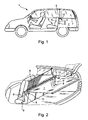
- a motor vehicle 1 in the present case in the form of a station wagon, has a vehicle interior in a rear area is provided with a loading space 2. Forward in the direction of travel connects to the cargo space 2 a rear seat in which a rear seat arrangement 3 is positioned.
- the rear seat arrangement 3 is with a backrest arrangement 4 provided.
- the Rear seat arrangement 3 divided into three across the vehicle width by three individually movable, side-by-side seat parts are provided. Each seat part has a backrest part of the backrest arrangement 4 on.
- the cargo space 2 is from the rear seat space by means of a flexible fabric separable in the form of a vertically stretchable separation network 6, around the front and rear passenger compartments against the cargo hold to protect objects thrown forward.
- the cargo space 2 by another flexible sheet in the form of a horizontal cover tarpaulin, for example, at the level of a vehicle curb protected against glimpses from above.
- the tarpaulin 7 is preferably designed opaque. Both the separation network 6 and the tarpaulin 7 are each on a winding shaft indicated in Fig. 3 11, 12 held and unrolled.
- the two winding shafts 11, 12 are horizontally and aligned in the vehicle transverse direction in one as a receiving device serving cassette housing 5 rotatably mounted.
- the cassette housing 5 is fixed, but detachable with a carrier arrangement connected in the form of a swivel bracket 8.
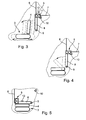
- the swivel bracket 8 has one on opposite sides Carrier legs 8 'on. Both carrier legs 8 'are common, horizontally and in the vehicle transverse direction aligned pivot axis 9 with With the help of appropriate swivel bearings, it can be swiveled on the vehicle side stored.
- the cassette housing 5 has in the area opposite to it Front each one parallel to the profile of the respective support leg 8 'running profile, each on the respective support leg a corresponding profile is assigned. By means of the profiles is the cassette housing 5 over its end faces from above insertable between the carrier legs and form-fitting between them held. Locking means are preferably provided which secure the position of the cassette housing 5 relative to the carrier legs 8 ' cause.
- the swivel bracket 8 and thus the two bracket legs 8 ' are in their upright functional position according to FIGS. 1 to 4 Locking means 10 secured.
- Locking means 10 can either Swivel bracket 8 locking device or a safety device be provided which have a certain mobility of the swivel bracket allows.
- the swivel bracket 8 is at least in a stop for the upper functional position is assigned to a swivel direction, around a constant end position for the cassette housing 5 and to enable the swivel bracket 8 in the upright functional position.
- the cassette housing 5 is inclusive the separation network 6 and the tarpaulin 7 by the Swivel bracket 8 blocked in an upright function position independently from the displacement of the vehicle seat arrangement in the longitudinal direction of the vehicle Third
- the pivot bracket 8 can also in a forward pivoted, lying functional position are transferred as soon as the Backrest arrangement 4 folded forward into a flat resting position is.
- the swivel bracket is also used for the lying functional position 8 at least one locking means 13 assigned to the swivel bracket 8th and thus also blocks the cassette housing 5 in this functional position.
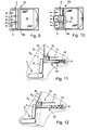
- an additional flexible fabric arrangement 17 is provided, that can be pulled out from three independently of one another, in the vehicle transverse direction juxtaposed sheet-like parts assembled is.
- the fabric parts of the fabric assembly 17 are each matched to the width of a corresponding backrest part and serve the between the cassette housing 5b and the respective Backrest position to bridge remaining gap, as shown 9 to 10 can be seen.
- the cassette case 5b is also on a swivel bracket 8b according to the previously described embodiments held so that for further explanation on the previously described embodiments according to FIGS. 1 to 7 becomes.
- Also in the embodiment according to FIGS. 8 to 10 are functionally the same Components have the same reference numerals, but with the addition of the letter "b" is used.
- linearly movable linear carrier 8c held by a carrier arrangement represents in the sense of the invention.
- the linear carrier 8c is preferably made of two arranged on opposite sides of the vehicle, piston-like support profiles that are identical to each other and are aligned parallel to each other. That is on these support profiles Cassette housing 5c releasably attached. Both beam profiles of the linear beam 8c are linearly movable in vehicle-mounted, hollow cylindrical receptacles slidable, which are part of the carrier arrangement.
- the hollow cylindrical Recordings are shown on corresponding, only schematically Body parts K of the vehicle body positioned vehicle-fixed.
- the Linear carrier 8c is by pressure means 18, in the form of a compression spring arrangement in the direction of travel forward pressure, so that it is permanent against the back of the backrest arrangement 4 of the rear seat arrangement 3 is pressed.
- the cassette housing 5c that is flush with the front faces of the support profiles of the linear support 8c closes, pressed against the backrest arrangement 5. If the individual seat parts of the rear seat arrangement 3 in the vehicle longitudinal direction are locked in different positions, that is Cassette housing 5 and thus also the linear carrier 8c on the rearmost Backrest of the respective seat part.
- the pressure means 18 represent a spring accumulator for the linear carrier 8c, as the drive device for the linear carrier 8c in the direction of travel serves in the front.
- Swivel beams can only be swiveled manually.
- Drive devices are assigned to swivel beams, which mechanically, can be carried out electrically, hydraulically or pneumatically.
- This Drive devices can only on the respective swivel bracket a single swivel direction or in both swivel directions apply an appropriate drive torque.
- For control is one Control unit provided that can either be operated manually or dependent Control movement commands corresponding to the signals from a suitable sensor system exercises on the swivel bracket. This can in particular the position detects the backrest and depending on the result of the detected backrest position a pivoting of the swivel bracket be made.
Abstract
Description
Die Erfindung betrifft eine Schutzvorrichtung für einen Laderaum eines Fahrzeugs mit wenigstens einer Aufnahmeeinrichtung für die Halterung wenigstens eines flexiblen Flächengebildes, das in wenigstens eine ausgezogene Funktionsposition sowie in eine kompakte Ruheposition im Bereich der Aufnahmeeinrichtung beweglich angeordnet ist.The invention relates to a protective device for a cargo space Vehicle with at least one receiving device for the holder at least one flexible sheet that is pulled into at least one Functional position and in a compact rest position in the area the receiving device is movably arranged.
Derartige Schutzvorrichtungen sind für Kraftfahrzeuge allgemein bekannt. Eine derartige Schutzvorrichtung weist als Aufnahmeeinrichtung für ein flexibles Flächengebilde in Form einer Abdeckplane und/oder eines Trenn-Netzes eine Wickelwelle auf, die in einem Kassettengehäuse oder mittels einer anders gestalteten Halterung fahrzeugfest im Bereich des Laderaumes gelagert ist. Das flexible Flächengebilde ist auf der Wickelwelle aufund abrollbar gehalten. In einer Ruheposition ist das Flächengebilde auf die Wickelwelle aufgerollt. Falls die Wickelwelle in einem Kassettengehäuse gelagert ist, ist das Flächengebilde in seiner aufgerollten Ruheposition nahezu vollständig innerhalb des Kassettengehäuses positioniert. Das Flächengebilde ist manuell oder mittels eines Antriebs in wenigstens eine teilweise oder vollständig ausgezogene Funktionsposition ausziehbar, indem das Flächengebilde in entsprechender Weise von der Wickelwelle abgerollt wird. Die Aufnahmeeinrichtung, d.h. insbesondere das Kassettengehäuse oder die Wickelwellenhalterung ist lösbar in den fahrzeugfesten Halterungen gehalten. Insbesondere bei einem Kombipersonenkraftwagen mit umklappbarer Rückenlehnenanordnung muß die Aufnahmeeinrichtung entfernt werden, um das Durchladen von sperrigen Gegenständen zu ermöglichen.Such protective devices are generally known for motor vehicles. Such a protective device has as a receiving device for a flexible Flat structures in the form of a tarpaulin and / or a separating network a winding shaft in a cassette housing or by means of a differently designed bracket fixed to the vehicle in the area of the cargo area is stored. The flexible fabric is open and open on the winding shaft held unrollable. The fabric is open in a rest position the winding shaft rolled up. If the winding shaft in a cassette housing is stored, the fabric is in its rolled-up rest position positioned almost entirely within the cassette housing. The fabric is manual or by means of a drive in at least one part or fully extended functional position extendable by the sheet is unrolled from the winding shaft in a corresponding manner becomes. The receiving device, i.e. especially the cassette case or the winding shaft holder is detachable in the vehicle-fixed holders held. Especially in a combination passenger car with a foldable Backrest assembly must remove the cradle to allow bulky items to be loaded.
Es ist daher auch bekannt, ein Flächengebilde in Form eines Trenn-Netzes mittels einer entsprechenden Aufnahmeeinrichtung direkt an einer Rückseite der Rückenlehnenanordnung zu befestigen. Sobald die Rückenlehnenanordnung vorne umgeklappt wird, wird auch die Aufnahmeeinrichtung mit nach vorne geklappt. Das Trenn-Netz ist so dimensioniert, dass es auch in der nach vorne umgeklappten Liegeposition der Rückenlehnenanordnung bis in einen Dachhimmelbereich des Fahrzeuginnenraumes nach oben ausziehbar und dort in dachseitigen Halterungen festlegbar ist.It is therefore also known to have a flat structure in the form of a separating network by means of a corresponding recording device directly on the back to attach the backrest assembly. Once the backrest assembly is folded down at the front, also the receiving device with folded forward. The separation network is dimensioned so that it also in the lying down position of the backrest arrangement folded forward to a headlining area of the vehicle interior can be pulled out at the top and fixed in the roof-side brackets.
Aufgabe der Erfindung ist es, eine Schutzvorrichtung der eingangs genannten Art zu schaffen, die im Vergleich zum Stand der Technik verbesserte Einsatzmöglichkeiten aufweist.The object of the invention is a protective device of the aforementioned To create kind that improved compared to the prior art Has possible uses.
Diese Aufgabe wird dadurch gelöst, dass die Aufnahmeeinrichtung an einer Trägeranordnung gehalten ist, die fahrzeugseitig derart beweglich gelagert ist, dass die Aufnahmeeinrichtung in wenigstens zwei unterschiedliche Lagepositionen innerhalb des Fahrzeugs überführbar ist. Erfindungsgemäß ist vorgesehen, die Aufnahmeeinrichtung an einer separaten Trägeranordnung vorzusehen, die unabhängig von einer Fahrzeugsitzanordnung und damit auch unabhängig von einer Rückenlehnenanordnung des Fahrzeuginnenraumes beweglich gelagert ist. Vorzugsweise ist die Aufnahmeeinrichtung an der Trägeranordnung lösbar gehalten. Die Schutzvorrichtung kann somit variabel in verschiedenen Raumabschnitten des Fahrzeuginnenraumes eingesetzt werden, ohne dass eine Abhängigkeit von der Position der Rückenlehnenanordnung gegeben ist.This object is achieved in that the receiving device on a Carrier arrangement is held, which is movably mounted on the vehicle side is that the receiving device in at least two different Position positions can be transferred within the vehicle. According to the invention the receiving device is provided on a separate carrier arrangement to be provided independently of a vehicle seat arrangement and thus also regardless of a backrest arrangement of the Vehicle interior is movably mounted. The receiving device is preferably releasably held on the carrier arrangement. The protection device can thus be variable in different sections of the vehicle interior can be used without dependency on the position of the backrest arrangement is given.
In Ausgestaltung der Erfindung sind Arretiermittel zur Sicherung der Trägeranordnung in den wenigstens zwei Lagepositionen vorgesehen. Dadurch ist die Trägeranordnung in jeder Lageposition stabil arretiert. Dies ist insbesondere vorteilhaft, falls das wenigstens eine flexible Flächengebilde als vertikal aufspannbares Trenn-Netz und damit als Rückhaltesicherung für in dem Laderaum befindliche Gegenstände gestaltet ist. Durch die Arretierung der Trägeranordnung und der an der Trägeranordnung gehaltenen Aufnahmeeinrichtung ist ein sicherer Rückhalt bei Aufprallbelastungen gewährleistet.In one embodiment of the invention, locking means for securing the carrier arrangement provided in the at least two position positions. Thereby the carrier arrangement is stably locked in any position. This is particularly advantageous if the at least one flexible fabric as a vertically stretchable separation network and thus as a restraint is designed for objects located in the hold. By locking the carrier arrangement and that held on the carrier arrangement A secure hold is guaranteed in the event of impact loads.
In weiterer Ausgestaltung der Erfindung ist die Trägeranordnung als um eine fahrzeugfeste, vorzugsweise in Fahrzeugquerrichtung ausgerichtete Schwenkachse beweglicher Schwenkträger gestaltet. Der Schwenkträger kann auf gegenüberliegenden Fahrzeugseiten jeweils einen Trägerschenkel aufweisen. Die Trägerschenkel können offen im Innenraum oder zumindest teilweise durch Innenraumverkleidungsteile verdeckt angeordnet sein.In a further embodiment of the invention, the carrier arrangement is around a vehicle-fixed, preferably oriented in the vehicle transverse direction Swivel axis designed swivel bracket. The swivel bracket can have a carrier leg on opposite sides of the vehicle exhibit. The carrier legs can be open in the interior or at least partially covered by interior trim parts his.
In weiterer Ausgestaltung der Erfindung ist die Trägeranordnung als vorzugsweise horizontal in Fahrzeuglängsrichtung verlagerbarer Linearträger gestaltet. Diese Ausgestaltung ist insbesondere vorteilhaft bei einer teilweise oder komplett verschiebbaren Fondsitzanordnung, da die Trägeranordnung der jeweils eingestellten Position einer Rückenlehnenanordnung der Fondsitzanordnung folgen kann. In a further embodiment of the invention, the carrier arrangement is preferred Linear carrier that can be moved horizontally in the longitudinal direction of the vehicle designed. This configuration is particularly advantageous with a partial or completely displaceable rear seat arrangement, since the carrier arrangement the respectively set position of a backrest arrangement can follow the rear seat arrangement.
In weiterer Ausgestaltung der Erfindung ist der Linearträger - in Fahrtrichtung gesehen - hinter einer Fahrzeugsitzanordnung positioniert und durch Druckmittel gegen eine Rückenlehnenanordnung der Fahrzeugsitzanordnung gedrückt gehalten. Dadurch ist die Aufnahmeeinrichtung für das wenigstens eine flexible Flächengebilde zwangsläufig immer in der bestmöglichen vorderen Position gehalten.In a further embodiment of the invention, the linear support is in the direction of travel seen - positioned behind a vehicle seat arrangement and through Pressure medium against a backrest arrangement of the vehicle seat arrangement held down. As a result, the receiving device for the at least a flexible fabric inevitably always in the best possible held in the front position.
In weiterer Ausgestaltung der Erfindung ist wenigstens ein flexibles Flächengebilde vorgesehen, das stirnseitig mit wenigstens einem Teil der Rückenlehnenanordnung lösbar verbunden ist. Diese Ausgestaltung ist insbesondere vorteilhaft für eine in der Fahrzeugbreite mehrteilig gestaltete Fahrzeugsitzanordnung, bei der die einzelnen Fahrzeugsitzteile in unterschiedlichen Positionen - auf die Fahrzeuglängsrichtung bezogen - ausgerichtet sein können. Vorzugsweise ist das jeweils mit der Rückenlehnenanordnung verbundene Flächengebilde in seiner Breite auf die Breite des jeweiligen Rückenlehnenteiles abgestimmt, so dass die Flächengebilde den jeweils verbleibenden, horizontalen Spalt zwischen der Aufnahmeeinrichtung, insbesondere einem Kassettengehäuse und der Rückseite der Rückenlehnenanordnung überdecken.In a further embodiment of the invention, at least one flexible flat structure is provided the front with at least part of the backrest arrangement is detachably connected. This configuration is special advantageous for a multi-part design in the vehicle width Vehicle seat arrangement in which the individual vehicle seat parts in different Positions - related to the vehicle's longitudinal direction - aligned could be. This is preferably with the backrest arrangement connected fabrics in width to the width of the respective Backrest part matched so that the fabrics each remaining horizontal gap between the receiving device, especially a cassette case and the back of the backrest assembly cover.
In weiterer Ausgestaltung der Erfindung ist wenigstens ein flexibles Flächengebilde von der Aufnahmeinrichtung aus stirnseitig mit einem Laderaumboden lösbar verbunden. Es ist somit wenigstens ein flexibles Flächengebilde vorgesehen, dass von der vorzugweise etwa auf Bordkantenhöhe positionierten Aufnahmeeinrichtung aus zum Laderaumboden hin nach unten aufspannbar ist. Dadurch ist es möglich, insbesondere bei umgeklappter Rückenlehnenanordnung den Laderaum gemeinsam mit einem nach oben ausgezogenen vertikalen Trenn-Netz über seine gesamte Höhe vollständig abzutrennen. Vorzugsweise ist auch das flexible Flächengebilde, das zur Aufspannung zum Laderaumboden nach unten dient, auf eine entsprechende Wickelwelle im Bereich der Aufnahmeeinrichtung auf- und abrollbar gelagert. Gleiches gilt für die zuvor beschriebenen, horizontal mit der Rückenlehnenanordnung verbindbaren Flächengebilde.In a further embodiment of the invention, at least one flexible flat structure is from the receiving device from the front with a loading space floor releasably connected. It is therefore at least a flexible sheet provided that from preferably about the curb height positioned receiving device from the cargo area floor can be stretched downwards. This makes it possible, especially when folded Backrest arrangement together with a cargo space vertical separating net extended upwards over its entire height completely separate. Preferably, the flexible fabric is also which is used to clamp down to the cargo floor on a corresponding winding shaft up and in the area of the receiving device unrolled stored. The same applies to the previously described, horizontal with the backrest arrangement connectable fabrics.
Weitere Vorteile und Merkmale der Erfindung ergeben sich aus den Ansprüchen sowie aus der nachfolgenden Beschreibung bevorzugter Ausführungsbeispiele der Erfindung, die anhand der Zeichnungen dargestellt sind.
- Fig. 1
- zeigt schematisch in teilweise aufgebrochener Seitendarstellung ein Kraftfahrzeug mit einer Ausführungsform einer erfindungsgemäßen Schutzvorrichtung,
- Fig. 2
- in perspektivischer; schematischer Darstellung die Schutzvorrichtung nach Fig. 1,
- Fig. 3
- schematisch in einer Seitendarstellung die Schutzvorrichtung nach Fig. 2,
- Fig. 4
- die Schutzvorrichtung nach Fig. 3 bei umgelegter Rückenlehnenanordnung,
- Fig. 5
- die Schutzvorrichtung nach Fig. 4 in einer unteren Endposition,
- Fig. 6
- schematisch in einer Darstellung ähnlich den Fig, 3 bis 5 eine weitere Ausführungsform einer erfindungsgemäßen Schutzvorrichtung,
- Fig. 7
- die Schutzvorrichtung nach Fig. 6 in einer weiteren Schutzposition,
- Fig. 8
- schematisch in einer Darstellung ähnlich den Fig. 3 bis 7 eine weitere Ausführungsform einer erfindungsgemäßen Schutzvorrichtung,
- Fig. 9
- schematisch eine Draufsicht auf einen mit der Schutzvorrichtung nach der Fig. 8 versehenen Fahrzeuginnenraum,
- Fig. 10
- den Fahrzeuginnenraum nach Fig. 9 mit in unterschiedlichen Stellpositionen befindlichen Fondsitzteilen,
- Fig. 11
- schematisch eine weitere Ausführungsform einer erfindungs-gemäßen Schutzvorrichtung in einer ersten Position und
- Fig. 12
- die Schutzvorrichtung nach Fig. 11 in einer zweiten Schutzposition.
- Fig. 1
- shows schematically in a partially broken side view a motor vehicle with an embodiment of a protective device according to the invention,
- Fig. 2
- in perspective; 1 shows the protective device according to FIG. 1,
- Fig. 3
- schematically in a side view the protective device according to FIG. 2,
- Fig. 4
- 3 with the backrest arrangement folded down,
- Fig. 5
- 4 in a lower end position,
- Fig. 6
- schematically in a representation similar to FIGS. 3 to 5, a further embodiment of a protective device according to the invention,
- Fig. 7
- 6 in a further protective position,
- Fig. 8
- schematically in a representation similar to FIGS. 3 to 7, a further embodiment of a protective device according to the invention,
- Fig. 9
- schematically a plan view of a vehicle interior provided with the protective device according to FIG. 8,
- Fig. 10
- 9 with the rear seat parts located in different positions,
- Fig. 11
- schematically a further embodiment of a protective device according to the invention in a first position and
- Fig. 12
- 11 in a second protective position.
Ein Kraftfahrzeug 1, vorliegend in Form eines Kombi-Personenkraftwagens,
weist einen Fahrzeuginnenraum auf, der in einem Heckbereich
mit einem Laderaum 2 versehen ist. In Fahrtrichtung nach vorne
schließt an den Laderaum 2 ein Fondsitzraum an, in dem eine Fondsitzanordnung
3 positioniert ist. Die Fondsitzanordnung 3 ist mit einer Rückenlehnenanordnung
4 versehen. Wie anhand der Fig. 2 erkennbar ist, ist die
Fondsitzanordnung 3 über die Fahrzeugbreite dreigeteilt, indem drei einzeln
verfahrbare, nebeneinander angeordnete Sitzteile vorgesehen sind.
Jeder Sitzteil weist jeweils einen Rückenlehnenteil der Rückenlehnenanordnung
4 auf.A
Der Laderaum 2 ist von dem Fondsitzraum mittels eines flexiblen Flächengebildes
in Form eines vertikal aufspannbaren Trenn-Netzes 6 abtrennbar,
um den front- und fondseitigen Fahrgastraum gegen aus dem Laderaum
nach vorne geschleuderte Gegenstände zu schützen. Zudem ist der Laderaum
2 durch ein weiteres flexbiles Flächengebilde in Form einer horizontal
aufspannbaren Abdeckplane etwa auf Höhe einer Fahrzeugbordkante insbesondere
gegen Einblicke von oben geschützt. Die Abdeckplane 7 ist
vorzugweise undurchsichtig gestaltet. Sowohl das Trenn-Netz 6 als auch
die Abdeckplane 7 sind jeweils auf einer in Fig. 3 angedeuteten Wickelwelle
11, 12 auf- und abrollbar gehalten. Die beiden Wickelwellen 11, 12 sind
horizontal und in Fahrzeugquerrichtung ausgerichtet in einem als Aufnahmevorrichtung
dienenden Kassettengehäuse 5 drehbeweglich gelagert.
Das Kassettengehäuse 5 ist fest, jedoch lösbar mit einer Trägeranordnung
in Form eines Schwenkträgers 8 verbunden.The
Der Schwenkträger 8 weist auf gegenüberliegenden Seiten jeweils einen
Trägerschenkel 8' auf. Beide Trägerschenkel 8' sind um eine gemeinsame,
horizontal und in Fahrzeugquerrichtung ausgerichtete Schwenkachse 9 mit
Hilfe entsprechender Schwenklagerungen fahrzeugseitig schwenkbeweglich
gelagert.The
Das Kassettengehäuse 5 weist im Bereich seiner gegenüberliegenden
Stirnseite jeweils eine parallel zu dem Profil des jeweiligen Trägerschenkels
8' verlaufende Profilierung auf, der am jeweiligen Trägerschenkel jeweils
eine korrespondierende Profilierung zugeordnet ist. Mittels der Profilierungen
ist das Kassettengehäuse 5 über seine Stirnflächen von oben her
zwischen die Trägerschenkel einsteckbar und formschlüssig zwischen diesen
gehalten. Vorzugsweise sind Rastmittel vorgesehen, die eine Positionssicherung
des Kassettengehäuses 5 relativ zu den Trägerschenkeln 8'
bewirken. Der Schwenkträger 8 und damit die beiden Trägerschenkel 8'
sind in ihrer aufrechten Funktionsposition gemäß den Fig. 1 bis 4 durch
Arretiermittel 10 gesichert. Als Arretiermittel 10 kann entweder eine den
Schwenkträger 8 blockierende Verschlußvorrichtung oder eine Fangvorrichtung
vorgesehen sein, die eine gewisse Beweglichkeit des Schwenkträgers
ermöglicht. Vorzugsweise ist dem Schwenkträger 8 mindestens in
einer Schwenkrichtung ein Anschlag für die obere Funktionsposition zugeordnet,
um eine gleichbleibende Endlage für das Kassettengehäuse 5 und
den Schwenkträger 8 in der aufrechten Funktionposition zu ermöglichen. The
Wie anhand der Fig. 3 gut erkennbar ist, ist das Kassettengehäuse 5 einschließlich
des Trenn-Netzes 6 und der Abdeckplane 7 durch den
Schwenkträger 8 in einer aufrechten Funktionposition blockiert unabhängig
von der in Fahrzeuglängsrichtung erfolgenden Verlagerung der Fahrzeugsitzanordnung
3.As can be seen clearly from FIG. 3, the
Wie in Fig. 5 gezeigt ist, kann der Schwenkträger 8 auch in eine nach vorne
geschwenkte, liegende Funktionsposition überführt werden, sobald die
Rückenlehnenanordnung 4 in eine flache Ruheposition nach vorne geklappt
ist. Auch für die liegende Funktionsposition ist dem Schwenkträger
8 wenigstens ein Arretiermittel 13 zugeordnet, das den Schwenkträger 8
und damit auch das Kassettengehäuse 5 in dieser Funktionsposition blockiert.As shown in Fig. 5, the
Beim Ausführungsbeispiel nach den Fig. 6 und 7 ist das Kassettengehäuse
5a ebenfalls an einem Schwenkträger 8a befestigt, wie dies bereits anhand
der Fig. 1 bis 5 beschrieben wurde. Funktionsgleiche Teile der Schutzvorrichtung
sind daher mit den gleichen Bezugszeichen unter Hinzufügung
des Buchstabens "a" versehen. Wesentlicher Unterschied bei der Ausführung
nach den Fig. 6 und 7 ist es, dass in dem Kassettengehäuse 5a noch
ein weiteres flexibles Flächengebilde 14 auf- und abrollbar gelagert ist, das
aus dem Kassettengehäuse 5a nach unten in Richtung zu einem Laderaumboden
16 ausziehbar ist. Hierzu sind im Bereich des Laderaumbodens
16 fahrzeugfeste Halterungen 15 vorgesehen, in denen ein vorderes
Stirnende des flexiblen Flächengebildes 14, vorzugweise eine Auszugsleiste,
lösbar befestigbar ist.6 and 7 is the
Beim Ausführungsbeispiel nach den Fig. 8 bis 10 ist in dem Kassettengehäuse
5b zusätzlich eine flexible Flächengebildeanordnung 17 vorgesehen,
die aus drei voneinander unabhängig ausziehbaren, in Fahrzeugquerrichtung
nebeneinander angeordneten Flächengebildeteilen zusammengesetzt
ist. Die Flächengebildeteile der Flächengebildeanordnung 17 sind jeweils
auf die Breite eines entsprechenden Rückenlehnenteiles abgestimmt
und dienen dazu, den zwischen dem Kassettengehäuse 5b und der jeweiligen
Rückenlehnenposition verbleibenden Spalt zu überbrücken, wie anhand
der Fig. 9 bis 10 erkennbar ist. Auch das Kassettengehäuse 5b ist
auf einem Schwenkträger 8b entsprechend den zuvor beschriebenen Ausführungsbeispielen
gehalten, so dass zur näheren Erläuterung auf die zuvor
beschriebenen Ausführungsformen nach den Fig. 1 bis 7 verwiesen
wird. Auch beim Ausführungsbeispiel nach den Fig. 8 bis 10 sind bei funktionsgleichen
Bauteilen die gleichen Bezugszeichen, jedoch unter Hinzufügung
des Buchstabens "b" verwendet.8 to 10 is in the
Beim Ausführungsbeispiel nach den Fig. 11 und 12 ist ein Kassettengehäuse
5c, das mit einem vertikalen Trenn-Netz 6c und einer horizontalen
Abdeckplane 7c versehen ist, auf einem horizontal und in Fahrzeuglängsrichtung
linear beweglichen Linearträger 8c gehalten, der eine Trägeranordnung
im Sinne der Erfindung darstellt. Der Linearträger 8c besteht vorzugsweise
aus zwei auf gegenüberliegenden Fahrzeugsseiten angeordneten,
kolbenartigen Trägerprofilen, die identisch zueinander gestaltet und
parallel zueinander ausgerichtet sind. Auf diesen Trägerprofilen ist das
Kassettengehäuse 5c lösbar befestigt. Beide Trägerprofile des Linearträgers
8c sind in fahrzeugfesten, hohlzylindrischen Aufnahmen linearbeweglich
verschiebbar, die Teil der Trägeranordnung sind. Die hohlzylindrischen
Aufnahmen sind an entsprechenden, lediglich schematisch dargestellten
Karosserieteilen K der Fahrzeugkarrosserie fahrzeugfest positioniert. Der
Linearträger 8c ist durch Druckmittel 18, vorliegend in Form einer Druckfederanordnung
in Fahrtrichtung nach vorne druckbelastet, so dass er permanent
gegen die Rückseite der Rückenlehnenanordnung 4 der Fondsitzanordnung
3 gedrückt wird. Dadurch wird auch das Kassettengehäuse 5c,
das bündig mit den vorderen Stirnseiten der Trägerprofile des Linearträgers
8c abschließt, gegen die Rückenlehnenanordnung 5 gedrückt gehalten.
Falls die einzelnen Sitzteile der Fondsitzanordnung 3 in Fahrzeuglängsrichtung
in unterschiedlichen Stellpositionen arretiert sind, liegt das
Kassettengehäuse 5 und damit auch der Linearträger 8c an der jeweils hintersten
Rückenlehne des jeweiligen Sitzteiles an.11 and 12 is a
Die Druckmittel 18 stellen für den Linearträger 8c einen Federspeicher dar,
der als Antriebseinrichtung für den Linearträger 8c in Fahrtrichtung nach
vorne dient.The pressure means 18 represent a spring accumulator for the
Die anhand der Ausführungsformen gemäß den Fig, 1 bis 10 beschriebenen Schwenkträger sind ausschließlich manuell verschwenkbar. Bei anderen, nicht dargestellten Ausführungsbeispielen der Erfindung sind derartigen Schwenkträgern Antriebseinrichtungen zugeordnet, die mechanisch, elektrisch, hydraulisch oder pneumatisch ausgeführt sein können. Diese Antriebseinrichtungen können auf den jeweiligen Schwenkträger in lediglich einer einzelnen Schwenkrichtung oder in beiden Schwenkrichtungen ein entsprechendes Antriebsmoment aufbringen. Zur Steuerung ist eine Steuereinheit vorgesehen, die entweder manuell bedienbar oder abhängig von den Signalen einer geeigneten Sensorik entsprechende Steuerbewegungsbefehle auf den Schwenkträger ausübt. Hierzu kann insbesondere die Stellung die Rückenlehne erfaßt und abhängig von dem Ergebnis der erfassten Rückenlehnenposition eine Verschwenkung des Schwenkträgers vorgenommen werden.The described with reference to the embodiments shown in FIGS. 1 to 10 Swivel beams can only be swiveled manually. With others Exemplary embodiments of the invention, not shown, are such Drive devices are assigned to swivel beams, which mechanically, can be carried out electrically, hydraulically or pneumatically. This Drive devices can only on the respective swivel bracket a single swivel direction or in both swivel directions apply an appropriate drive torque. For control is one Control unit provided that can either be operated manually or dependent Control movement commands corresponding to the signals from a suitable sensor system exercises on the swivel bracket. This can in particular the position detects the backrest and depending on the result of the detected backrest position a pivoting of the swivel bracket be made.
Claims (10)
Applications Claiming Priority (2)
| Application Number | Priority Date | Filing Date | Title |
|---|---|---|---|
| DE10140256 | 2001-08-07 | ||
| DE10140256A DE10140256B4 (en) | 2001-08-07 | 2001-08-07 | Protective device for a loading space of a vehicle |
Publications (3)
| Publication Number | Publication Date |
|---|---|
| EP1283130A2 true EP1283130A2 (en) | 2003-02-12 |
| EP1283130A3 EP1283130A3 (en) | 2004-01-14 |
| EP1283130B1 EP1283130B1 (en) | 2006-09-13 |
Family
ID=7695669
Family Applications (1)
| Application Number | Title | Priority Date | Filing Date |
|---|---|---|---|
| EP02016224A Expired - Lifetime EP1283130B1 (en) | 2001-08-07 | 2002-07-19 | Protection system for a vehicle luggage compartment |
Country Status (5)
| Country | Link |
|---|---|
| US (1) | US6843518B2 (en) |
| EP (1) | EP1283130B1 (en) |
| JP (1) | JP2003054320A (en) |
| KR (1) | KR20030014117A (en) |
| DE (2) | DE10140256B4 (en) |
Cited By (11)
| Publication number | Priority date | Publication date | Assignee | Title |
|---|---|---|---|---|
| DE10307212A1 (en) * | 2003-02-20 | 2004-09-09 | Bos Gmbh & Co. Kg | Luggage space cover with additional roller blind has roller blind attached at one edge to second reel shaft and second drive device for turning second reel shaft in rewinding direction |
| DE102004021556A1 (en) * | 2004-05-03 | 2005-12-01 | Daimlerchrysler Ag | System for covering and dividing the loading space in a car especially an estate has roller blind that can be stored in a cassette at different positions in the vehicle |
| EP1623870A2 (en) | 2004-08-03 | 2006-02-08 | Intier Automotive Eybl (Germany) GmbH | Cargo space separator |
| EP1749698A2 (en) | 2005-08-02 | 2007-02-07 | Intier Automotive Eybl (Germany) GmbH | Luggage compartment cover |
| DE102005036805A1 (en) * | 2005-08-02 | 2007-03-29 | Intier Automotive Eybl (Germany) Gmbh | Loading space partition for expandable loading space of motor vehicle, has two dividing elements whereby detent or locking means are cooperated further to produce two hinge connections on second dividing element |
| FR2900611A1 (en) * | 2006-05-05 | 2007-11-09 | Renault Sas | ADJUSTABLE LENGTH LUGGAGE LUGGAGE DEVICE FOR MOTOR VEHICLE BOX AND CORRESPONDING VEHICLE |
| EP2072327A1 (en) * | 2007-12-20 | 2009-06-24 | Centre d'etude et de recherche pour l'automobile (CERA) | Release device of the luggage load space of a motor vehicle |
| EP2067641A3 (en) * | 2007-12-08 | 2009-08-05 | Dr.Ing. h.c.F. Porsche Aktiengesellschaft | Vehicle with roller blind |
| FR2992598A1 (en) * | 2012-06-27 | 2014-01-03 | Renault Sa | Vehicle i.e. motor vehicle, has articulated support arms pivoting between top position and bottom position, and canopy balancing mechanism comprising crossed cables between support arms for parallelizing pivoting movement of arms |
| FR2992599A1 (en) * | 2012-06-27 | 2014-01-03 | Renault Sa | Vehicle, has swiveling arms articulated along horizontal axis at mid height of luggage compartment and swiveling between high position in which canopy is in high use position and low position in which canopy is in low arrangement position |
| FR3046970A3 (en) * | 2016-01-25 | 2017-07-28 | Renault Sas | DEVICE FOR VERTICAL SEPARATION BETWEEN A ROW OF SEATS AND A LOADING AREA OF A MOTOR VEHICLE |
Families Citing this family (30)
| Publication number | Priority date | Publication date | Assignee | Title |
|---|---|---|---|---|
| DE10140256B4 (en) * | 2001-08-07 | 2012-09-06 | Bos Gmbh & Co. Kg | Protective device for a loading space of a vehicle |
| DE10335055B4 (en) * | 2003-07-31 | 2010-04-08 | Bayerische Motoren Werke Aktiengesellschaft | Cover for a gap |
| DE10354882A1 (en) * | 2003-11-25 | 2005-06-30 | Volkswagen Ag | Separating device for luggage space of convertible car, had dividing panel and additional pull-out part for further dividing the space |
| DE102004029042A1 (en) * | 2004-06-08 | 2005-12-29 | Bos Gmbh & Co. Kg | Protective device for a vehicle interior |
| US20070018442A1 (en) * | 2005-07-22 | 2007-01-25 | Kwok Ming Y | Vehicle driver and passenger restraining device |
| US8993055B2 (en) | 2005-10-27 | 2015-03-31 | Asm International N.V. | Enhanced thin film deposition |
| US20070119885A1 (en) * | 2005-11-28 | 2007-05-31 | Toyoda Gosei Co. Ltd. | Floor console with reconfigurable storage |
| DE102006034635A1 (en) * | 2006-07-27 | 2008-01-31 | Dr.Ing.H.C. F. Porsche Ag | Protecting device for loading space of motor vehicle, has planar structure formed as spacer structure, where planar structure has reduced light transmission at horizontal protecting position and increased transmission in vertical position |
| JP4802921B2 (en) * | 2006-08-02 | 2011-10-26 | 日産自動車株式会社 | Vehicle accessory storage part formation structure |
| EP1905630B1 (en) * | 2006-09-27 | 2011-04-13 | BOS GmbH & Co. KG | Manually operated window roller blind |
| KR100794025B1 (en) * | 2006-12-15 | 2008-01-10 | 현대자동차주식회사 | Combination type cargo screen possible moving front and rear |
| US7595270B2 (en) | 2007-01-26 | 2009-09-29 | Asm America, Inc. | Passivated stoichiometric metal nitride films |
| US7598170B2 (en) | 2007-01-26 | 2009-10-06 | Asm America, Inc. | Plasma-enhanced ALD of tantalum nitride films |
| US20090033114A1 (en) * | 2007-08-02 | 2009-02-05 | Thomas Steigerwald | Loading area cover for a motor vehicle |
| JP5551681B2 (en) | 2008-04-16 | 2014-07-16 | エーエスエム アメリカ インコーポレイテッド | Atomic layer deposition of metal carbide films using aluminum hydrocarbon compounds |
| DE102009051283B3 (en) * | 2009-10-29 | 2010-12-09 | Hs Genion Gmbh Engineering Services | Load compartment separation with pull-out limitation device |
| JP5340888B2 (en) * | 2009-10-30 | 2013-11-13 | 芦森工業株式会社 | Vehicle cover device |
| DE102010047849A1 (en) * | 2010-10-07 | 2012-04-12 | Gm Global Technology Operations Llc (N.D.Ges.D. Staates Delaware) | Slideable loading area for motor vehicle, is displaceable by multiple rollers and is arranged at front end of loading area, which protrudes in usage position in direction of loading space |
| JP5285093B2 (en) * | 2011-01-25 | 2013-09-11 | 日本発條株式会社 | Cover connection structure |
| US9016758B1 (en) * | 2013-12-09 | 2015-04-28 | Ford Global Technologies, Llc | Tonneau cover gap hider for adjustable rear seats |
| GB2527053B (en) * | 2014-06-10 | 2018-02-28 | Jaguar Land Rover Ltd | Load space covering device |
| KR102216575B1 (en) | 2014-10-23 | 2021-02-18 | 에이에스엠 아이피 홀딩 비.브이. | Titanium aluminum and tantalum aluminum thin films |
| US9610897B2 (en) | 2015-05-12 | 2017-04-04 | Ford Global Technologies, Llc | Multi-function/position cover system for a vehicle cargo area |
| JP6485219B2 (en) * | 2015-05-26 | 2019-03-20 | トヨタ紡織株式会社 | Tonneau cover device for vehicle |
| US9731654B2 (en) * | 2015-10-15 | 2017-08-15 | Ford Global Technologies Llc | Sliding cargo tonneau cover |
| DE102015220192B3 (en) * | 2015-10-16 | 2017-03-09 | Bos Gmbh & Co. Kg | Protective device for a loading space of a motor vehicle |
| US9975491B2 (en) * | 2015-10-19 | 2018-05-22 | Ford Global Technologies Llc | Retractable cargo cover system |
| DE102016115667A1 (en) * | 2016-08-24 | 2018-03-01 | Dr. Ing. H.C. F. Porsche Aktiengesellschaft | Device for fastening a safety net in a vehicle |
| US10611314B2 (en) * | 2017-09-29 | 2020-04-07 | Faurecia Automotive Seating, Llc | Vehicle privacy screen |
| US10513225B2 (en) * | 2018-02-13 | 2019-12-24 | GM Global Technology Operations LLC | Motor vehicle with height adjustable floor |
Family Cites Families (24)
| Publication number | Priority date | Publication date | Assignee | Title |
|---|---|---|---|---|
| US4168094A (en) * | 1976-10-30 | 1979-09-18 | Toyota Jidosha Kogyo Kabushiki Kaisha | Device for covering up a parcel floor in an automobile |
| DE2739741A1 (en) * | 1977-09-03 | 1979-03-15 | Daimler Benz Ag | A REAR DOOR LOCKING A LOAD AREA OF A CAR |
| FR2431395A1 (en) * | 1978-07-21 | 1980-02-15 | Citroen Sa | REMOVABLE REAR RANGE VEHICLE |
| JP2926255B2 (en) * | 1990-03-31 | 1999-07-28 | 日本発条株式会社 | Automotive guard net |
| DE4200021C2 (en) | 1992-01-02 | 1994-05-05 | Butz Peter Verwaltung | Load compartment covering device, such as a roller blind or the like, for the trunk of a vehicle |
| DE4313855C2 (en) * | 1993-04-28 | 2003-11-06 | Daimler Chrysler Ag | Designed as a roller blind covering device for a loading compartment in a motor vehicle |
| DE4424498C2 (en) * | 1994-07-12 | 1996-08-14 | Baumeister & Ostler Gmbh Co | Cover roller blind or device for a trunk of a motor vehicle |
| DE4438910C1 (en) * | 1994-11-03 | 1996-03-21 | Butz Peter Verwaltung | Restraint device for the hold of motor vehicles, such as. B. for combination cars or large passenger cars |
| JP3924814B2 (en) * | 1995-09-26 | 2007-06-06 | マツダ株式会社 | Vehicle seat device |
| DE19537768C1 (en) * | 1995-10-11 | 1996-11-28 | Butz Peter Verwaltung | Retainer and cover device for cargo space of estate cars |
| US5702143A (en) * | 1996-03-15 | 1997-12-30 | Tachi-S Co., Ltd. | Arrangement for anchoring a guard net in automobile |
| JP3674148B2 (en) * | 1996-05-21 | 2005-07-20 | トヨタ車体株式会社 | Vehicle partition device |
| JPH1024790A (en) * | 1996-07-11 | 1998-01-27 | Ashimori Ind Co Ltd | Winding type load collapse preventing device for vehicle |
| DE19710787C1 (en) * | 1997-03-17 | 1998-04-23 | Butz Peter Verwaltung | Retention or cover device for load space of combination motor car |
| SE508854C2 (en) * | 1997-03-27 | 1998-11-09 | Volvo Ab | Vehicle reinforcement device |
| FR2767099B1 (en) * | 1997-08-05 | 1999-09-24 | Renault | DEVICE FOR ADJUSTING THE REAR LOADING PART OF A MOTOR VEHICLE INTERIOR |
| JP2000085365A (en) * | 1998-09-10 | 2000-03-28 | Toyota Motor Corp | Trunk room divided structure |
| FR2810935B1 (en) * | 2000-07-03 | 2002-08-30 | Cera | LUGGAGE RETAINER FOR A MOTOR VEHICLE |
| US6474725B2 (en) * | 2000-07-26 | 2002-11-05 | Meritor Light Vehicle Technology, Llc | Reinforced cargo doors |
| DE10057572C2 (en) * | 2000-11-20 | 2002-11-14 | Butz Peter Verwaltung | Loading space covering and / or loading space separating device for the loading or luggage space of a vehicle |
| DE10102792A1 (en) * | 2001-01-22 | 2002-08-01 | Webasto Vehicle Sys Int Gmbh | Load compartment cover for passenger cars |
| DE10103593A1 (en) * | 2001-01-26 | 2002-08-22 | Audi Ag | Restraint device for load space has guide device with first and second swiveling arms |
| DE10140256B4 (en) * | 2001-08-07 | 2012-09-06 | Bos Gmbh & Co. Kg | Protective device for a loading space of a vehicle |
| KR100772330B1 (en) * | 2006-07-27 | 2007-10-31 | 한일이화주식회사 | Cargo screen assembly for vehicle |
-
2001
- 2001-08-07 DE DE10140256A patent/DE10140256B4/en not_active Expired - Fee Related
-
2002
- 2002-07-19 EP EP02016224A patent/EP1283130B1/en not_active Expired - Lifetime
- 2002-07-19 DE DE50208117T patent/DE50208117D1/en not_active Expired - Lifetime
- 2002-08-05 KR KR1020020046093A patent/KR20030014117A/en active IP Right Grant
- 2002-08-07 US US10/213,783 patent/US6843518B2/en not_active Expired - Fee Related
- 2002-08-07 JP JP2002230174A patent/JP2003054320A/en active Pending
Non-Patent Citations (1)
| Title |
|---|
| None |
Cited By (16)
| Publication number | Priority date | Publication date | Assignee | Title |
|---|---|---|---|---|
| DE10307212A1 (en) * | 2003-02-20 | 2004-09-09 | Bos Gmbh & Co. Kg | Luggage space cover with additional roller blind has roller blind attached at one edge to second reel shaft and second drive device for turning second reel shaft in rewinding direction |
| DE10307212B4 (en) * | 2003-02-20 | 2005-03-24 | Bos Gmbh & Co. Kg | Load compartment cover with additional roller blind |
| DE102004021556A1 (en) * | 2004-05-03 | 2005-12-01 | Daimlerchrysler Ag | System for covering and dividing the loading space in a car especially an estate has roller blind that can be stored in a cassette at different positions in the vehicle |
| EP1623870A2 (en) | 2004-08-03 | 2006-02-08 | Intier Automotive Eybl (Germany) GmbH | Cargo space separator |
| EP1749698A3 (en) * | 2005-08-02 | 2008-07-30 | Magna Exteriors & Interiors Management GmbH | Luggage compartment cover |
| DE102005036805A1 (en) * | 2005-08-02 | 2007-03-29 | Intier Automotive Eybl (Germany) Gmbh | Loading space partition for expandable loading space of motor vehicle, has two dividing elements whereby detent or locking means are cooperated further to produce two hinge connections on second dividing element |
| EP1749698A2 (en) | 2005-08-02 | 2007-02-07 | Intier Automotive Eybl (Germany) GmbH | Luggage compartment cover |
| DE102005036805B4 (en) * | 2005-08-02 | 2010-01-21 | Magna Exteriors & Interiors Management Gmbh | Storage space partition |
| FR2900611A1 (en) * | 2006-05-05 | 2007-11-09 | Renault Sas | ADJUSTABLE LENGTH LUGGAGE LUGGAGE DEVICE FOR MOTOR VEHICLE BOX AND CORRESPONDING VEHICLE |
| WO2007128936A1 (en) * | 2006-05-05 | 2007-11-15 | Renault S.A.S. | Length-adjustable device for concealing luggage for motor vehicle trunk and motor vehicle equipped with same |
| EP2067641A3 (en) * | 2007-12-08 | 2009-08-05 | Dr.Ing. h.c.F. Porsche Aktiengesellschaft | Vehicle with roller blind |
| EP2072327A1 (en) * | 2007-12-20 | 2009-06-24 | Centre d'etude et de recherche pour l'automobile (CERA) | Release device of the luggage load space of a motor vehicle |
| FR2925420A1 (en) * | 2007-12-20 | 2009-06-26 | Cera | DEVICE FOR RELEASING THE LOADING SPACE OF BAGGAGE OF A MOTOR VEHICLE |
| FR2992598A1 (en) * | 2012-06-27 | 2014-01-03 | Renault Sa | Vehicle i.e. motor vehicle, has articulated support arms pivoting between top position and bottom position, and canopy balancing mechanism comprising crossed cables between support arms for parallelizing pivoting movement of arms |
| FR2992599A1 (en) * | 2012-06-27 | 2014-01-03 | Renault Sa | Vehicle, has swiveling arms articulated along horizontal axis at mid height of luggage compartment and swiveling between high position in which canopy is in high use position and low position in which canopy is in low arrangement position |
| FR3046970A3 (en) * | 2016-01-25 | 2017-07-28 | Renault Sas | DEVICE FOR VERTICAL SEPARATION BETWEEN A ROW OF SEATS AND A LOADING AREA OF A MOTOR VEHICLE |
Also Published As
| Publication number | Publication date |
|---|---|
| DE10140256A1 (en) | 2003-03-06 |
| DE10140256B4 (en) | 2012-09-06 |
| DE50208117D1 (en) | 2006-10-26 |
| US20030102691A1 (en) | 2003-06-05 |
| US6843518B2 (en) | 2005-01-18 |
| JP2003054320A (en) | 2003-02-26 |
| EP1283130B1 (en) | 2006-09-13 |
| EP1283130A3 (en) | 2004-01-14 |
| KR20030014117A (en) | 2003-02-15 |
Similar Documents
| Publication | Publication Date | Title |
|---|---|---|
| DE10140256B4 (en) | Protective device for a loading space of a vehicle | |
| EP1479564B1 (en) | Protection device for the interior of a vehicle | |
| EP1473199B1 (en) | Partition device for vehicle interior | |
| DE10345181B4 (en) | Vehicle seat assembly | |
| EP1574394A1 (en) | Functional unit for an inner space of a vehicle | |
| DE102017010794A1 (en) | vehicle seat | |
| DE4108189C1 (en) | ||
| DE19932256B4 (en) | Industrial truck with a safety cell for a driver | |
| DE102010046635B4 (en) | Motor vehicle with a passenger compartment and a rear-side cargo space and storage container for this | |
| EP1749698A2 (en) | Luggage compartment cover | |
| EP1207078B1 (en) | Load compartment cover and/or load compartment partitioning device for a vehicle load or luggage compartment | |
| DE4313855C2 (en) | Designed as a roller blind covering device for a loading compartment in a motor vehicle | |
| DE10032658B4 (en) | Center console in a motor vehicle interior | |
| DE102005035271A1 (en) | Motor vehicle, especially private motor vehicle, has rear parcel shelf which in not-in-use position extends with regard to direction of travel behind seat backrests along backrests | |
| DE4128701A1 (en) | Sepn. of luggage space from passenger space in car - partition attached to backrest of rear seat and underside of roof | |
| DE19909142C1 (en) | Cargo space divider for motor vehicles consists of flat flexible material passing over two horizontal vertically adjustable bars to form pockets for small items | |
| DE10256347A1 (en) | Protection device for a load space in a motor vehicle especially a station wagon has unrolling cover which can be locked in different positions | |
| DE102008048360A1 (en) | Seating unit has vehicle seat and rotating unit for rotating vehicle seat around vertical rotational axis in use position and pivoting arrangement is provided for pivoting vehicle seat together with rotating unit | |
| DE10204664B4 (en) | Motor vehicle with a dividable by a partition interior | |
| DE10223682B4 (en) | Protective device for a loading space of a motor vehicle | |
| DE19811162A1 (en) | Device for securing cargo | |
| EP3476650B1 (en) | Seat frame of a vehicle seat | |
| DE10134613A1 (en) | Windshield has roller blind of flexible material, and roll-up device for it mounted to extend transversely in floor region of vehicle, with end sections of roll-up device each supporting pivotable support post | |
| DE4445854C2 (en) | Holder for long parts, especially skis, in the interior of passenger cars | |
| EP1155922A2 (en) | Retaining device for the luggage compartment of a vehicle, e.g. a station wagon or the like |
Legal Events
| Date | Code | Title | Description |
|---|---|---|---|
| PUAI | Public reference made under article 153(3) epc to a published international application that has entered the european phase |
Free format text: ORIGINAL CODE: 0009012 |
|
| AK | Designated contracting states |
Designated state(s): AT BE BG CH CY CZ DE DK EE ES FI FR GB GR IE IT LI LU MC NL PT SE SK TR |
|
| AX | Request for extension of the european patent |
Extension state: AL LT LV MK RO SI |
|
| PUAL | Search report despatched |
Free format text: ORIGINAL CODE: 0009013 |
|
| AK | Designated contracting states |
Kind code of ref document: A3 Designated state(s): AT BE BG CH CY CZ DE DK EE ES FI FR GB GR IE IT LI LU MC NL PT SE SK TR |
|
| AX | Request for extension of the european patent |
Extension state: AL LT LV MK RO SI |
|
| RIC1 | Information provided on ipc code assigned before grant |
Ipc: 7B 60N 2/36 B Ipc: 7B 60R 21/06 B Ipc: 7B 60R 5/04 A |
|
| 17P | Request for examination filed |
Effective date: 20040603 |
|
| 17Q | First examination report despatched |
Effective date: 20040823 |
|
| AKX | Designation fees paid |
Designated state(s): DE FR GB SE |
|
| GRAP | Despatch of communication of intention to grant a patent |
Free format text: ORIGINAL CODE: EPIDOSNIGR1 |
|
| GRAS | Grant fee paid |
Free format text: ORIGINAL CODE: EPIDOSNIGR3 |
|
| GRAA | (expected) grant |
Free format text: ORIGINAL CODE: 0009210 |
|
| AK | Designated contracting states |
Kind code of ref document: B1 Designated state(s): DE FR GB SE |
|
| REG | Reference to a national code |
Ref country code: GB Ref legal event code: FG4D Free format text: NOT ENGLISH |
|
| REF | Corresponds to: |
Ref document number: 50208117 Country of ref document: DE Date of ref document: 20061026 Kind code of ref document: P |
|
| REG | Reference to a national code |
Ref country code: SE Ref legal event code: TRGR |
|
| GBT | Gb: translation of ep patent filed (gb section 77(6)(a)/1977) |
Effective date: 20070103 |
|
| ET | Fr: translation filed | ||
| PLBE | No opposition filed within time limit |
Free format text: ORIGINAL CODE: 0009261 |
|
| STAA | Information on the status of an ep patent application or granted ep patent |
Free format text: STATUS: NO OPPOSITION FILED WITHIN TIME LIMIT |
|
| 26N | No opposition filed |
Effective date: 20070614 |
|
| PGFP | Annual fee paid to national office [announced via postgrant information from national office to epo] |
Ref country code: GB Payment date: 20080723 Year of fee payment: 7 |
|
| GBPC | Gb: european patent ceased through non-payment of renewal fee |
Effective date: 20090719 |
|
| PG25 | Lapsed in a contracting state [announced via postgrant information from national office to epo] |
Ref country code: GB Free format text: LAPSE BECAUSE OF NON-PAYMENT OF DUE FEES Effective date: 20090719 |
|
| PGFP | Annual fee paid to national office [announced via postgrant information from national office to epo] |
Ref country code: FR Payment date: 20100802 Year of fee payment: 9 Ref country code: SE Payment date: 20100723 Year of fee payment: 9 |
|
| REG | Reference to a national code |
Ref country code: SE Ref legal event code: EUG |
|
| REG | Reference to a national code |
Ref country code: FR Ref legal event code: ST Effective date: 20120330 |
|
| PG25 | Lapsed in a contracting state [announced via postgrant information from national office to epo] |
Ref country code: FR Free format text: LAPSE BECAUSE OF NON-PAYMENT OF DUE FEES Effective date: 20110801 |
|
| PG25 | Lapsed in a contracting state [announced via postgrant information from national office to epo] |
Ref country code: SE Free format text: LAPSE BECAUSE OF NON-PAYMENT OF DUE FEES Effective date: 20110720 |
|
| PGFP | Annual fee paid to national office [announced via postgrant information from national office to epo] |
Ref country code: DE Payment date: 20140723 Year of fee payment: 13 |
|
| REG | Reference to a national code |
Ref country code: DE Ref legal event code: R119 Ref document number: 50208117 Country of ref document: DE |
|
| PG25 | Lapsed in a contracting state [announced via postgrant information from national office to epo] |
Ref country code: DE Free format text: LAPSE BECAUSE OF NON-PAYMENT OF DUE FEES Effective date: 20160202 |