EP1282179A2 - Negative electrode for rechargeable battery - Google Patents

Negative electrode for rechargeable battery Download PDF

Info

Publication number
EP1282179A2
EP1282179A2 EP02017241A EP02017241A EP1282179A2 EP 1282179 A2 EP1282179 A2 EP 1282179A2 EP 02017241 A EP02017241 A EP 02017241A EP 02017241 A EP02017241 A EP 02017241A EP 1282179 A2 EP1282179 A2 EP 1282179A2
Authority
EP
European Patent Office
Prior art keywords
layer
lithium
negative electrode
rechargeable battery
current collector
Prior art date
Legal status (The legal status is an assumption and is not a legal conclusion. Google has not performed a legal analysis and makes no representation as to the accuracy of the status listed.)
Withdrawn
Application number
EP02017241A
Other languages
German (de)
French (fr)
Other versions
EP1282179A3 (en
Inventor
Mitsuhiro Mori
Hironori Yamamoto
Koji Utsugi
Jiro Iriyama
Tamaki Miura
Mariko Miyachi
Current Assignee (The listed assignees may be inaccurate. Google has not performed a legal analysis and makes no representation or warranty as to the accuracy of the list.)
NEC Corp
Original Assignee
NEC Corp
Priority date (The priority date is an assumption and is not a legal conclusion. Google has not performed a legal analysis and makes no representation as to the accuracy of the date listed.)
Filing date
Publication date
Application filed by NEC Corp filed Critical NEC Corp
Publication of EP1282179A2 publication Critical patent/EP1282179A2/en
Publication of EP1282179A3 publication Critical patent/EP1282179A3/en
Withdrawn legal-status Critical Current

Links

Images

Classifications

    • HELECTRICITY
    • H01ELECTRIC ELEMENTS
    • H01MPROCESSES OR MEANS, e.g. BATTERIES, FOR THE DIRECT CONVERSION OF CHEMICAL ENERGY INTO ELECTRICAL ENERGY
    • H01M4/00Electrodes
    • H01M4/02Electrodes composed of, or comprising, active material
    • H01M4/13Electrodes for accumulators with non-aqueous electrolyte, e.g. for lithium-accumulators; Processes of manufacture thereof
    • HELECTRICITY
    • H01ELECTRIC ELEMENTS
    • H01MPROCESSES OR MEANS, e.g. BATTERIES, FOR THE DIRECT CONVERSION OF CHEMICAL ENERGY INTO ELECTRICAL ENERGY
    • H01M4/00Electrodes
    • H01M4/02Electrodes composed of, or comprising, active material
    • H01M4/13Electrodes for accumulators with non-aqueous electrolyte, e.g. for lithium-accumulators; Processes of manufacture thereof
    • H01M4/133Electrodes based on carbonaceous material, e.g. graphite-intercalation compounds or CFx
    • HELECTRICITY
    • H01ELECTRIC ELEMENTS
    • H01MPROCESSES OR MEANS, e.g. BATTERIES, FOR THE DIRECT CONVERSION OF CHEMICAL ENERGY INTO ELECTRICAL ENERGY
    • H01M4/00Electrodes
    • H01M4/02Electrodes composed of, or comprising, active material
    • H01M4/13Electrodes for accumulators with non-aqueous electrolyte, e.g. for lithium-accumulators; Processes of manufacture thereof
    • H01M4/137Electrodes based on electro-active polymers
    • HELECTRICITY
    • H01ELECTRIC ELEMENTS
    • H01MPROCESSES OR MEANS, e.g. BATTERIES, FOR THE DIRECT CONVERSION OF CHEMICAL ENERGY INTO ELECTRICAL ENERGY
    • H01M4/00Electrodes
    • H01M4/02Electrodes composed of, or comprising, active material
    • H01M4/36Selection of substances as active materials, active masses, active liquids
    • H01M4/362Composites
    • H01M4/366Composites as layered products
    • HELECTRICITY
    • H01ELECTRIC ELEMENTS
    • H01MPROCESSES OR MEANS, e.g. BATTERIES, FOR THE DIRECT CONVERSION OF CHEMICAL ENERGY INTO ELECTRICAL ENERGY
    • H01M4/00Electrodes
    • H01M4/02Electrodes composed of, or comprising, active material
    • H01M4/36Selection of substances as active materials, active masses, active liquids
    • H01M4/60Selection of substances as active materials, active masses, active liquids of organic compounds
    • H01M4/602Polymers
    • HELECTRICITY
    • H01ELECTRIC ELEMENTS
    • H01MPROCESSES OR MEANS, e.g. BATTERIES, FOR THE DIRECT CONVERSION OF CHEMICAL ENERGY INTO ELECTRICAL ENERGY
    • H01M4/00Electrodes
    • H01M4/02Electrodes composed of, or comprising, active material
    • H01M4/64Carriers or collectors
    • HELECTRICITY
    • H01ELECTRIC ELEMENTS
    • H01MPROCESSES OR MEANS, e.g. BATTERIES, FOR THE DIRECT CONVERSION OF CHEMICAL ENERGY INTO ELECTRICAL ENERGY
    • H01M4/00Electrodes
    • H01M4/02Electrodes composed of, or comprising, active material
    • H01M2004/026Electrodes composed of, or comprising, active material characterised by the polarity
    • H01M2004/027Negative electrodes
    • HELECTRICITY
    • H01ELECTRIC ELEMENTS
    • H01MPROCESSES OR MEANS, e.g. BATTERIES, FOR THE DIRECT CONVERSION OF CHEMICAL ENERGY INTO ELECTRICAL ENERGY
    • H01M4/00Electrodes
    • H01M4/02Electrodes composed of, or comprising, active material
    • H01M4/04Processes of manufacture in general
    • HELECTRICITY
    • H01ELECTRIC ELEMENTS
    • H01MPROCESSES OR MEANS, e.g. BATTERIES, FOR THE DIRECT CONVERSION OF CHEMICAL ENERGY INTO ELECTRICAL ENERGY
    • H01M4/00Electrodes
    • H01M4/02Electrodes composed of, or comprising, active material
    • H01M4/36Selection of substances as active materials, active masses, active liquids
    • H01M4/58Selection of substances as active materials, active masses, active liquids of inorganic compounds other than oxides or hydroxides, e.g. sulfides, selenides, tellurides, halogenides or LiCoFy; of polyanionic structures, e.g. phosphates, silicates or borates
    • H01M4/583Carbonaceous material, e.g. graphite-intercalation compounds or CFx
    • H01M4/587Carbonaceous material, e.g. graphite-intercalation compounds or CFx for inserting or intercalating light metals
    • YGENERAL TAGGING OF NEW TECHNOLOGICAL DEVELOPMENTS; GENERAL TAGGING OF CROSS-SECTIONAL TECHNOLOGIES SPANNING OVER SEVERAL SECTIONS OF THE IPC; TECHNICAL SUBJECTS COVERED BY FORMER USPC CROSS-REFERENCE ART COLLECTIONS [XRACs] AND DIGESTS
    • Y02TECHNOLOGIES OR APPLICATIONS FOR MITIGATION OR ADAPTATION AGAINST CLIMATE CHANGE
    • Y02EREDUCTION OF GREENHOUSE GAS [GHG] EMISSIONS, RELATED TO ENERGY GENERATION, TRANSMISSION OR DISTRIBUTION
    • Y02E60/00Enabling technologies; Technologies with a potential or indirect contribution to GHG emissions mitigation
    • Y02E60/10Energy storage using batteries

Definitions

  • the present invention relates to a negative electrode for a rechargeable battery (secondary battery) including lithium metal or lithium alloy as an active material.
  • Rechargeable batteries using lithium metal and lithium alloy as negative electrodes show superior energy density compared with lithium-ion rechargeable battery using a graphite negative electrode.
  • a negative electrode contains lithium metal as an active material, some drawbacks for cycling efficiency and safety must be overcome. Due to high chemical activity of lithium, a part of the lithium deposited on the negative electrode in charge process becomes inactivated, and then various lithium compounds like lithium hydroxide, lithium oxide, lithium carbonate, are formed on the electrode surface. Thus, the formed film is composed of various products. Such a non-uniform film gives a localized deposition of lithium on the negative electrode surface. Lithium inactivation induces to lower the cycling efficiency, and the localized deposition of lithium forms dendrite structure, which can cause internal short circuit. The pulverization of the lithium alloy due to a large volume change decreases charge-discharge efficiency (cycling efficiency). The volume change upon cycling must be controlled to materialize a metallic lithium electrode in commercial rechargeable batteries.
  • some proposals have been made to overcome the problems for the lithium metal or alloy negative electrode. For instance, some proposals include the suppression of the dendrite growth by a stable film such as lithium fluoride on the electrode surface.
  • JP-A-7(1995)-302617 describes a lithium negative electrode covered with a lithium fluoride film formed by a reaction between lithium compounds existing on the lithium surface and hydrogen fluoride by means of exposing the lithium electrode to an electrolyte solution containing the hydrogen fluoride. Hydrogen fluoride is generated through a reaction between LiPF 6 and a trace amount of water.
  • JP-A-8(1996)-250108 describes the formation of lithium fluoride on the surface of a negative electrode by a reaction between a mixed gas containing argon and hydrogen fluoride and aluminum-lithium alloy.
  • a mixed gas containing argon and hydrogen fluoride and aluminum-lithium alloy a mixed gas containing argon and hydrogen fluoride and aluminum-lithium alloy.
  • the uniform reaction is not likely to proceed, and the uniform lithium fluoride film can be hardly formed. Accordingly, the lithium rechargeable battery with the sufficient cycle characteristics is difficult to be fabricated.
  • JP-A-11(1999)-288706 describes the formation of a surface film containing sodium chloride as a main component, which has a uniform (100) crystal plane preferentially oriented. In this manner, the uniform deposition and dissolution reaction of lithium suppresses the dendrite formation. Therefore, the cycling efficiency and safety of the battery could be improved.
  • the surface film is desired to contain lithium halide; a solid solution composed of LiF and at least one of the lithium compounds such as LiCl, LiBr and LiI.
  • the negative electrode for the non-aqueous electrolyte battery is fabricated by dipping a lithium sheet, having a preferentially oriented (100) crystal surface and formed by rolling, into an electrolyte containing a fluorine molecule or a fluorine ion and at least one of a chlorine molecule or a chlorine ion, a bromine molecule or a bromine ion and an iodine molecule or an iodine ion for forming the solid solution film.
  • the rolled lithium metal sheet is likely to be exposed to air, thereby forming a film on its surface due to water moisture. Suppression of the dendrite formation is insufficient because the non-uniform chemical compounds hardly give the uniform and stable film on the lithium surface.
  • the formation of the lithium halide film on the lithium or lithium alloy layer provides suppression effect of the dendrite formation during the initial stage to some degree, the protection ability of the film decreases gradually upon cycling. This suggests that the internal stress is generated in the lithium halide film by diffusion and/or migration of lithium ions. In other words, the volume of the lithium or lithium alloy layer is changed significantly, due to the occlusion and the release of the lithium, while the volume of lithium halide layer remains unchanged. The internal stress destroys a part of the lithium halide film to lower the suppressing effect of the dendrite formation.
  • an object of the present invention is to provide a negative electrode for rechargeable battery which can prevent the dendrite formation in a lithium metal negative electrode for a longer period of time and is excellent in its energy density and cycle life.
  • the present invention provides a negative electrode for a rechargeable battery including: a current collector, a first layer containing a conductive material to occlude and release lithium ion, the first layer formed on the current collector, a second layer containing a metal selected from lithium and lithium alloy, the second layer formed on the first layer, and a third layer containing a lithium ion conductive material, the third layer formed on the second layer.
  • the conductive material of the first layer may be replaced with conductive polymer.
  • the third layer prevents the lithium and/or the lithium alloy in the second layer from being in contact with the electrolyte and smoothly feeds the lithium to the second layer to improve the efficiency of the negative electrode.
  • the third layer cannot follow the volume change of the second layer.
  • the first layer has relaxation effect to the second layer, which shows a large volume change. That is, the first layer can occlude and release a part of the lithium incorporated in the second layer. This reduces the volume change of the second layer. Such a smaller volume change inhibits to cause pulverization.
  • the negative electrode of the present invention includes a layer structure having a second layer sandwiched between a first layer and a third layer.
  • the third layer allows the lithium to smoothly reach to the second layer and prevents the electrolyte from direct contact with the lithium or the lithium alloy, thereby maintaining the cycling efficiency to be higher and effectively preventing the degradation of the negative electrode such as the dendrite formation.
  • the third layer is affected by the volume change of the second layer, indicating that the protective function is reduced.
  • the electrode structure in the present invention is composed of the first layer under the second layer in addition to the third layer on the second layer.
  • the first layer made of the material, which ahs lithium storage ability, may occlude and release part of the lithium, which is to be occluded and released by the second layer. Accordingly, the volume change of the second layer due to the lithium occlusion and release is reduced to significantly enhance the durability of the negative electrode.
  • the cycle life and the cycling efficiency are remarkably improved by the synergistic effect of the first and the third layers.
  • the first layer suppresses the capacity change of the second layer by the occlusion and the release of the lithium. This means to inhibit the degradation of the third layer without capacity change.
  • the first layer interposed between the current collector and the second layer in the negative electrode of the present invention excellently improves the interlayer adhesion of the layer structure including the current collector, the first layer and the second layer.
  • the selection of the material of the first layer such as the carbon having less capacity change due to the occlusion and the release of the lithium than the second layer more significantly improves the adhesion elevating effect.
  • the carbon is preferably contained as a main component.
  • main component refers to a component having a mass % of 50 or more with respect to the total amount.
  • the conductivity of the material of the first layer maintains the conduction between the lithium-containing layer and the current collector to efficiently prevent the dendrite formation.
  • the conductive material which can occlude and release lithium ion of the first layer can be replaced with conductive polymer usually having proper elasticity.
  • the elastic material of the first layer can absorb the distortion energy in the second layer.
  • the first layer keeps the interlayer adhesion force and the durability of the layer structure including the current collector, the first layer and the second layer.
  • the elastic material includes the conducting polymer, having the oxidation-reduction potential close to the operation voltage of the negative electrode, such as polyacetylene, its derivative, polythiophene, its derivative and the conductive polymer prepared by the condensation of quinone-based compound, and further includes polymer compound containing rubber-like material such as styrene, butadiene, polyethylene and polypropylene mixed with an electron-conductive material.
  • the conducting polymer having the oxidation-reduction potential close to the operation voltage of the negative electrode, such as polyacetylene, its derivative, polythiophene, its derivative and the conductive polymer prepared by the condensation of quinone-based compound, and further includes polymer compound containing rubber-like material such as styrene, butadiene, polyethylene and polypropylene mixed with an electron-conductive material.
  • the first layer with the conductive material may include graphite, amorphous carbon, diamond-like carbon, carbon nanotube and the composite thereof.
  • the graphite is preferable among these, because the graphite is excellent in voltage planarization and the adhesiveness with the current collector such as copper.
  • the graphite contains less impurity than the amorphous material because the graphite is thermally treated at a temperature much higher than that for the amorphous materials.
  • the second layer occluding and releasing the lithium is made of the lithium alone, or binary or ternary alloy consisting of the lithium and other metals such as Al, Si, Pb, Sn, In, Bi, Ag, Ba, Ca, Hg, Pd, Pt, Te, Zn and La.
  • the amorphous alloy is desirable for the lithium alloy because the amorphous structure hardly generates the degradation such as crystal grain boundary and other defects due to the non-uniformity.
  • the third layer acting as the protective layer for the second layer prevents the direct contact between the electrolyte and the lithium to maintain the initial battery performance during the repeated charge-discharge cycles.
  • the third layer is preferably made of material having reactivity with the electrolyte lower than the lithium.
  • the material of the third layer includes lithium carbonate, lithium oxide, lithium sulfide, and lithium halide such as lithium fluoride, lithium chloride, lithium bromide and lithium iodide, and composite thereof.
  • the lithium halide is the most preferable and the amorphous structure is preferable because the lithium halide is fairly stable, and the amorphous structure hardly generates the degradation such as crystal grain boundary and other defects due to the non-uniformity.
  • the third layer contains at least two components including solid glassy electrolyte and solid polymer electrolyte.
  • the solid glassy electrolyte includes oxides and sulfides containing at least one of lithium, calcium, sodium, magnesium, beryllium, potassium, silicon, phosphorus, boron, nitrogen, aluminum and transition metals, and more specifically, SiO 2 , Li 3 PO 4 , B 2 O 3 , P 2 S 5 , P 2 O 5 , LiSO 4 , Li x PO y N z , Li 2 O and the composite thereof.
  • the most preferable third layer includes at least one of Li 2 O, SiO 2 , P 2 O 5 and Li x PO y N z .
  • the solid polymer electrolyte includes polyethylene oxide (PEO), polypropylene oxide (PPO), polyvinylidene fluoride (PVDF), polyacrylonitrile (PAN) and derivatives thereof. These compounds are desirably amorphous.
  • the second layer is formed on the first layer
  • the third layer is formed on the second layer.
  • the third layer preferably forms the surface or the outermost layer.
  • the number of each of the first to third layers can be singular or plural, and for example, the layer structure having the first layer, the second layer, the first layer, the second layer and the third layer stacked in this turn can be used.
  • the entire surface of the second layer is almost covered with the third layer, a partial surface of the second layer may be covered therewith.
  • the first layer is preferably in contact with the second layer, and the third layer is preferably in contact with the second layer. In this layer structure, the volume change of the second layer can be smaller.
  • the thicknesses of the first and third layers are preferably about 0.1 to 20 ⁇ m, and that of the second layer is preferably about 0.5 to 30 ⁇ m. Around these thicknesses, the extent of the volume change of the second layer is small, and the rechargeable battery can be obtained having the well-balanced energy density, cycle life and efficiency.
  • the lithium content varies from 10 % to 90 % depending on the progress of the charge and discharge reaction.
  • the first to third layers can be formed by using various film coating methods including a molten liquid cooling method, a liquid rapid cooling method, an atomize method, a vacuum deposition method, a sputtering method, a plasma CVD method, an optical CVD method, a thermal CVD method and a sol-gel method.
  • the target lithium compound may be incorporated into the electrolyte as an additive generated by a reaction with lithium metal.
  • the negative electrode in the present invention is excellent in its flexibility with respect to the capacity change of the second layer, the evenness of the ion distribution and the physical and chemical stability, thereby effectively preventing the formation of the dendrite and the pulverization of the lithium to increase the cycle efficiency and the lifetime.
  • the second layer containing the active metallic lithium and sandwiched by the first and third layers suppresses the reaction between the lithium and moisture introduced from the raw material such as the electrolyte, the positive electrode and the separator during the assembly of the battery.
  • the positive electrode usable in the lithium rechargeable battery of the present invention is obtained by applying, on a substrate such as an aluminum foil, the mixture prepared by dispersing and mixing the positive electrode material, the conductive material such as the carbon black and the bonding agent such as the PVDF with a solvent such as N-methyl-2-pyrrolidone.
  • the positive electrode material includes a composite oxide such as Li x MO 2 (M refers to at least a transition metal) such as Li x CoO 2 , Li x NiO 2 , Li x Mn 2 O 4 , Li x MnO 3 and Li x Ni y Co 1-y O 2 , an organic sulfur compound and conductive polymer.
  • the lithium rechargeable battery of the present invention is fabricated by stacking the negative electrodes and the positive electrodes interposing the separators therebetween followed by winding, if necessary, and accommodating the stacked structure into a battery can or sealing the stacked structure with a flexible film formed by stacking synthetic resin and metal foil.
  • the separator is a porous film made of polyolefin such as polypropylene and polyethylene or fluorocarbon resin.
  • the solvent containing lithium salt is an organic solvent, which includes cyclic carbonates such as propylene carbonate (PC), ethylene carbonate (EC), butylene carbonate (BC) and vinylene carbonate (VC), linear carbonates such as dimethyl carbonate, diethyl carbonate, ethylmethyl carbonate and dipropyl carbonate (DPC), aliphatic carboxylate esters such as methyl formate, methyl acetate and ethyl propionate, ⁇ - lactones such as ⁇ -butyrolactone, linear ethers such as 1,2-ethoxyethane (DEE) and ethoxymethoxyethane (EME), cyclic ethers such as tetrahydrofuran and 2-methyltetrahydrofuran, and aprotic organic solvents such as dimethylsulfoxide, 1,3-dioxolane, formamide, acetoamide, dimethylformamide, dioxolane, acetonitrile, propyln
  • the lithium salt is dissolved into one or more organic solvents.
  • the lithium salt includes LiPF 6 , LiAsF 6 , LiAlCl 4 , LiClO 4 , LiBF 4 , LiSbF 6 , LiCF 3 SO 3 , LiC 4 F 9 CO 3 , LiC(CF 3 SO 2 ) 2 , LiN(CF 3 SO 2 ) 2 , LiN(C 2 F 5 SO 2 ) 2 , LiB 10 Cl 10 , lithium lower aliphatic carboxylate, chloloboran lithium, lithium tetraphenylborate, LiBr, LiI, LiSCN, LiCl and imides.
  • Polymer electrolyte may be used in place of the liquid electrolyte.
  • the shape of the rechargeable battery of the present invention is not especially restricted, the cylindrical, the polygonal or the coin-shaped battery is used.
  • a negative electrode in accordance with an embodiment of the present invention includes a current collector 1a and a layer structure 5a stacked thereon.
  • the layer structure 5a includes a first layer 2a on the current collector 1a, a second layer on the first layer 2a and a third layer 4a on the second layer 3a.
  • a rechargeable battery 11 includes a positive electrode 12 and a negative electrode 13, which face to each other interposing electrolyte solution 14 and a porous separator 15 located therein.
  • the porous separator 15 extends nearly parallel to the negative electrode active material-containing layer 18.
  • a copper foil obtained by electrolysis having a thickness of 10 ⁇ m was used as the current collector 1a shown in Fig.1.
  • the first layer 2a was formed by applying a paste to the copper foil 1a followed by drying and compression.
  • the paste was prepared by mixing graphite with poly(vinylidene fluoride) and dissolving the mixture into a solvent (N-methyl-2-pyrrolodon).
  • the second layer 3a and the third layer 4a made of lithium-silicon alloy and lithium fluoride (LiF), respectively, were formed in a vacuum vapor deposition apparatus having a degree of vacuum from 10 -6 to 10 -5 Pa by vacuum-depositing the lithium-silicon alloy or the LiF to a roll having a width of 60 mm by means of electron beam or resistance heating.
  • the capacity of the negative electrode thus formed was the total between the capacity of the graphite and the capacity of the lithium-silicon alloy.
  • the negative electrode prepared in this manner and a separator having vapor-deposited lithium thereon was welded to a nickel tab to obtain an electric connectivity.
  • a positive electrode was formed by applying positive electrode paint to the surface of aluminum foil followed by drying and compression.
  • the positive electrode paint was prepared by mixing Li x Mn 2 O 4 with carbon black and poly(vinylidene fluoride) and dispersing and dissolving the mixture into a solvent (N-methyl-2-pyrrolodon). Then, 1 mol/L of LiPF 6 was dissolved into a mixed solvent of ethylene carbonate and diethyl carbonate to provide an electrolyte solution.
  • the negative electrode member and the positive electrode were wound interposing the separator there between to prepare a polygonal rechargeable battery.
  • a charge rate, a discharge rate, a charge terminating voltage and a discharge terminating voltage were determined to be 1C, 0.5C, 4.3V and 3.0V, respectively. Cycling efficiency is obtained by dividing a discharge capacity (mAh) after 300 cycles by the discharge capacity after 10 cycles. The results obtained in Examples are shown in Table 1.
  • Example 1 The initial charge and discharge efficiency and cycling efficiency in Example 1 were significantly higher than those of Comparative Example 1.
  • the improvement of the initial charge and discharge efficiency is probably because the LiF layer existing on the interface suppresses the decomposition of the electrolyte to reduce the irreversible capacity.
  • the improvement of the capacity-maintaining rate is probably because the LiF layer and the graphite layer suppress the volume change due to the charge and the discharge.
  • Example 2 to 9 the negative electrodes were fabricated by using the materials for the first layer 2a, the second layer 3a and the third layer 4a as specified in Table 1.
  • the discharge depth of the lithium metal negative electrode was adjusted to be 33.3 %.
  • the negative electrodes and the batteries of Examples 2 to 9 were evaluated similarly to Example 1, and the results are shown in Table 1.
  • a negative electrode was fabricated in accordance with the same conditions as those of Example 1 except that 1M of LiN(C 2 F 5 SO 2 ) 2 was dissolved in ethylene carbonate and diethyl carbonate in place of the electrolyte in Example 1, and the materials for the second layer 3a and the third layer 4a were polycrystalline Li-Si alloy and LiF which were introduced therein by the reaction between N - (C 2 F 5 SO 2 ) 2 and lithium, respectively.
  • the negative electrode and the battery of Example 10 were evaluated similarly to Example 1, and the results are shown in Table 1.
  • Example 10 both of the initial charge and discharge efficiency and the capacity-maintaining rate of Example 10 were lower than those of Example 1 using the amorphous Li-Si alloy. This proves that the efficiencies of the charge and discharge reaction can be further improved by using the third layer having the amorphous structure without the crystal grain boundary and other defects.
  • Example 1 graphite Li-Si LiF 98.9 89.4
  • Example 2 graphite Li-Al LiF-Li 2 CO 3 99.0 88.7
  • Example 3 graphite Li-Sn SiO 2 -Li 2 O-P 2 S 6 98.4 88.6
  • Example 4 graphite Li SiO 2 -Li 2 O-P 2 S 6 100.0 85.4
  • Example 5 amorphous carbon Li-Si LiF-Li 2 CO 3 97.8 83.2
  • Example 6 amorphous carbon Li-Si LiF 92.4 84.8
  • Example 7 amorphous carbon Li-Al LiF-Li 2 CO 3 92.1 83.5
  • Example 8 amorphous carbon Li-Sn SiO 2 -Li 2 O-P 2 S 6 91.6 82.5
  • Example 9 amorphous carbon Li-Si SiO 2 -Li 2 O-P 2 S 6 92.9 83.8
  • Example10 graphite Li-Si LiF 87.
  • a battery was fabricated in accordance with the same conditions as those of Example 1 except that lithium-aluminum alloy was used as the second layer 3a of the negative electrode and, as shown in Fig.3, the second layer 3a was directly formed on the current collector 1a without the first layer.
  • the cycle characteristics of the thus obtained battery were evaluated similarly to Example 1. As shown in Table 2, the initial charge and discharge efficiency was 87.2 % and the capacity-maintaining rate was below 10 %.
  • a negative electrode of Comparative Example 2 includes the first layer 2a and the second layer 3a on the current collector 1a
  • a negative electrode of Comparative Example 3 includes the second layer 3a and the third layer 4a on the current collector 1a.
  • Batteries of Comparative Examples 2 to 5 were fabricated similarly to Example 1 except that materials forming each of the layers were specified in Table 2. The cycle characteristics of the thus obtained batteries evaluated similarly to Example 1 were shown in Table 2. 2a 3a 4a Initial charge and discharge efficiency (%) Capacity maintaining rate (%) Comp.Ex.1 ⁇ Li-Al ⁇ 87.2 ⁇ 10 Comp.Ex.2 graphite Li-Si ⁇ 80.1 42.4 Comp.Ex.3 ⁇ Li-Si LiF-Li 2 CO 3 79.5 45.0

Landscapes

  • Chemical & Material Sciences (AREA)
  • Chemical Kinetics & Catalysis (AREA)
  • Electrochemistry (AREA)
  • General Chemical & Material Sciences (AREA)
  • Engineering & Computer Science (AREA)
  • Materials Engineering (AREA)
  • Composite Materials (AREA)
  • Manufacturing & Machinery (AREA)
  • Battery Electrode And Active Subsutance (AREA)
  • Secondary Cells (AREA)

Abstract

A negative electrode for a rechargeable battery including: a current collector (1a), a first layer (2a) containing a conductive material to occlude and release lithium ion, the first layer (2a) formed on the current collector (1a), a second layer (3a) containing a metal selected from lithium and lithium alloy, the second layer (3a) formed on the first layer (2a), and a third layer (4a) containing a lithium ion conductive material, the third layer (4a) formed on the second layer (3a). The third layer (4a) prevents the lithium and/or the lithium alloy in the second layer (3a) from being in contact with the electrolyte and smoothly feeds the lithium to the second layer (3a) to improve the efficiency of the negative electrode. The first layer (2a) can occlude and release the part of the lithium to be occluded and released, thereby reducing the volume change of the second layer (3a). Such a structure of the negative electrode enables us to enhance cycling efficiency, and to attain long cycle life and good safety.

Description

BACKGROUND OF THE INVENTION (a) Field of the Invention
The present invention relates to a negative electrode for a rechargeable battery (secondary battery) including lithium metal or lithium alloy as an active material.
(b) Description of the Related Art
Rechargeable batteries using lithium metal and lithium alloy as negative electrodes show superior energy density compared with lithium-ion rechargeable battery using a graphite negative electrode. However, when a negative electrode contains lithium metal as an active material, some drawbacks for cycling efficiency and safety must be overcome. Due to high chemical activity of lithium, a part of the lithium deposited on the negative electrode in charge process becomes inactivated, and then various lithium compounds like lithium hydroxide, lithium oxide, lithium carbonate, are formed on the electrode surface. Thus, the formed film is composed of various products. Such a non-uniform film gives a localized deposition of lithium on the negative electrode surface. Lithium inactivation induces to lower the cycling efficiency, and the localized deposition of lithium forms dendrite structure, which can cause internal short circuit. The pulverization of the lithium alloy due to a large volume change decreases charge-discharge efficiency (cycling efficiency). The volume change upon cycling must be controlled to materialize a metallic lithium electrode in commercial rechargeable batteries.
Various proposals have been made to overcome the problems for the lithium metal or alloy negative electrode. For instance, some proposals include the suppression of the dendrite growth by a stable film such as lithium fluoride on the electrode surface.
JP-A-7(1995)-302617 describes a lithium negative electrode covered with a lithium fluoride film formed by a reaction between lithium compounds existing on the lithium surface and hydrogen fluoride by means of exposing the lithium electrode to an electrolyte solution containing the hydrogen fluoride. Hydrogen fluoride is generated through a reaction between LiPF6 and a trace amount of water.
Normally, it is quite difficult to obtain a uniform surface film, because active lithium metal reacts with almost all chemical species in an electrolyte solution. The formed film consisting of various compounds is heterogeneous, which are derived from some competitive reactions on the lithium surface. As for topology, dendrite shape forms on the non-uniform surface. In the case of this method for fluoride film formation, hence, it is hardly available to attain a uniform and stable film.
JP-A-8(1996)-250108 describes the formation of lithium fluoride on the surface of a negative electrode by a reaction between a mixed gas containing argon and hydrogen fluoride and aluminum-lithium alloy. However, when another lithium compound exists on the lithium surface in advance and especially a plurality of species are present, the uniform reaction is not likely to proceed, and the uniform lithium fluoride film can be hardly formed. Accordingly, the lithium rechargeable battery with the sufficient cycle characteristics is difficult to be fabricated.
JP-A-11(1999)-288706 describes the formation of a surface film containing sodium chloride as a main component, which has a uniform (100) crystal plane preferentially oriented. In this manner, the uniform deposition and dissolution reaction of lithium suppresses the dendrite formation. Therefore, the cycling efficiency and safety of the battery could be improved. The surface film is desired to contain lithium halide; a solid solution composed of LiF and at least one of the lithium compounds such as LiCl, LiBr and LiI. Preferably, the negative electrode for the non-aqueous electrolyte battery is fabricated by dipping a lithium sheet, having a preferentially oriented (100) crystal surface and formed by rolling, into an electrolyte containing a fluorine molecule or a fluorine ion and at least one of a chlorine molecule or a chlorine ion, a bromine molecule or a bromine ion and an iodine molecule or an iodine ion for forming the solid solution film. In this art, the rolled lithium metal sheet is likely to be exposed to air, thereby forming a film on its surface due to water moisture. Suppression of the dendrite formation is insufficient because the non-uniform chemical compounds hardly give the uniform and stable film on the lithium surface.
Further, the above prior art includes the following common problems.
Although the formation of the lithium halide film on the lithium or lithium alloy layer provides suppression effect of the dendrite formation during the initial stage to some degree, the protection ability of the film decreases gradually upon cycling. This suggests that the internal stress is generated in the lithium halide film by diffusion and/or migration of lithium ions. In other words, the volume of the lithium or lithium alloy layer is changed significantly, due to the occlusion and the release of the lithium, while the volume of lithium halide layer remains unchanged. The internal stress destroys a part of the lithium halide film to lower the suppressing effect of the dendrite formation.
SUMMARY OF THE INVENTION
In view of the foregoing, an object of the present invention is to provide a negative electrode for rechargeable battery which can prevent the dendrite formation in a lithium metal negative electrode for a longer period of time and is excellent in its energy density and cycle life.
The present invention provides a negative electrode for a rechargeable battery including: a current collector, a first layer containing a conductive material to occlude and release lithium ion, the first layer formed on the current collector, a second layer containing a metal selected from lithium and lithium alloy, the second layer formed on the first layer, and a third layer containing a lithium ion conductive material, the third layer formed on the second layer.
In the present invention, the conductive material of the first layer may be replaced with conductive polymer.
In accordance with the present invention, the third layer prevents the lithium and/or the lithium alloy in the second layer from being in contact with the electrolyte and smoothly feeds the lithium to the second layer to improve the efficiency of the negative electrode. In the three-layer structure of the negative electrode, however, the third layer cannot follow the volume change of the second layer. The first layer has relaxation effect to the second layer, which shows a large volume change. That is, the first layer can occlude and release a part of the lithium incorporated in the second layer. This reduces the volume change of the second layer. Such a smaller volume change inhibits to cause pulverization.
The above and other objects, features and advantages of the present invention will be more apparent from the following description.
BRIEF DESCRIPTION OF DRAWINGS
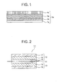
  • Fig.1 is a cross sectional view showing an embodiment of a negative electrode of the present invention.
  • Fig.2 is a cross sectional view showing an embodiment of a lithium rechargeable battery.
  • Fig.3 is a cross sectional view showing the negative electrode of a rechargeable battery in Comparative Example 1.
  • Fig.4 is a cross sectional view showing the negative electrode of a rechargeable battery in Comparative Example 2.
  • Fig.5 is a cross sectional view showing the negative electrode of a rechargeable battery in Comparative Example 3.
  • PREFERRED EMBODIMENTS OF THE INVENTION
    Now, the present invention is more specifically described.
    The negative electrode of the present invention includes a layer structure having a second layer sandwiched between a first layer and a third layer. The third layer allows the lithium to smoothly reach to the second layer and prevents the electrolyte from direct contact with the lithium or the lithium alloy, thereby maintaining the cycling efficiency to be higher and effectively preventing the degradation of the negative electrode such as the dendrite formation.
    However, in the structure in which the third layer is present on the second layer, the third layer is affected by the volume change of the second layer, indicating that the protective function is reduced.
    Accordingly, the electrode structure in the present invention is composed of the first layer under the second layer in addition to the third layer on the second layer. The first layer made of the material, which ahs lithium storage ability, may occlude and release part of the lithium, which is to be occluded and released by the second layer. Accordingly, the volume change of the second layer due to the lithium occlusion and release is reduced to significantly enhance the durability of the negative electrode. The cycle life and the cycling efficiency are remarkably improved by the synergistic effect of the first and the third layers. In other words, the first layer suppresses the capacity change of the second layer by the occlusion and the release of the lithium. This means to inhibit the degradation of the third layer without capacity change.
    The first layer interposed between the current collector and the second layer in the negative electrode of the present invention excellently improves the interlayer adhesion of the layer structure including the current collector, the first layer and the second layer. The selection of the material of the first layer such as the carbon having less capacity change due to the occlusion and the release of the lithium than the second layer more significantly improves the adhesion elevating effect. In the first layer, the carbon is preferably contained as a main component. In this text, "main component" refers to a component having a mass % of 50 or more with respect to the total amount.
    The conductivity of the material of the first layer maintains the conduction between the lithium-containing layer and the current collector to efficiently prevent the dendrite formation.
    In the present invention, the conductive material, which can occlude and release lithium ion of the first layer can be replaced with conductive polymer usually having proper elasticity. The elastic material of the first layer can absorb the distortion energy in the second layer. The first layer keeps the interlayer adhesion force and the durability of the layer structure including the current collector, the first layer and the second layer. The elastic material includes the conducting polymer, having the oxidation-reduction potential close to the operation voltage of the negative electrode, such as polyacetylene, its derivative, polythiophene, its derivative and the conductive polymer prepared by the condensation of quinone-based compound, and further includes polymer compound containing rubber-like material such as styrene, butadiene, polyethylene and polypropylene mixed with an electron-conductive material.
    The first layer with the conductive material may include graphite, amorphous carbon, diamond-like carbon, carbon nanotube and the composite thereof. The graphite is preferable among these, because the graphite is excellent in voltage planarization and the adhesiveness with the current collector such as copper. In addition, the graphite contains less impurity than the amorphous material because the graphite is thermally treated at a temperature much higher than that for the amorphous materials.
    The second layer occluding and releasing the lithium is made of the lithium alone, or binary or ternary alloy consisting of the lithium and other metals such as Al, Si, Pb, Sn, In, Bi, Ag, Ba, Ca, Hg, Pd, Pt, Te, Zn and La. The amorphous alloy is desirable for the lithium alloy because the amorphous structure hardly generates the degradation such as crystal grain boundary and other defects due to the non-uniformity.
    The third layer acting as the protective layer for the second layer prevents the direct contact between the electrolyte and the lithium to maintain the initial battery performance during the repeated charge-discharge cycles. The third layer is preferably made of material having reactivity with the electrolyte lower than the lithium.
    The material of the third layer includes lithium carbonate, lithium oxide, lithium sulfide, and lithium halide such as lithium fluoride, lithium chloride, lithium bromide and lithium iodide, and composite thereof. Among these, the lithium halide is the most preferable and the amorphous structure is preferable because the lithium halide is fairly stable, and the amorphous structure hardly generates the degradation such as crystal grain boundary and other defects due to the non-uniformity.
    The third layer contains at least two components including solid glassy electrolyte and solid polymer electrolyte. The solid glassy electrolyte includes oxides and sulfides containing at least one of lithium, calcium, sodium, magnesium, beryllium, potassium, silicon, phosphorus, boron, nitrogen, aluminum and transition metals, and more specifically, SiO2, Li3PO4, B2O3, P2S5, P2O5, LiSO4, LixPOyNz, Li2O and the composite thereof. The most preferable third layer includes at least one of Li2O, SiO2, P2O5 and LixPOyNz. The solid polymer electrolyte includes polyethylene oxide (PEO), polypropylene oxide (PPO), polyvinylidene fluoride (PVDF), polyacrylonitrile (PAN) and derivatives thereof. These compounds are desirably amorphous.
    In the layer structure of the negative electrode, the second layer is formed on the first layer, and the third layer is formed on the second layer. The third layer preferably forms the surface or the outermost layer. The number of each of the first to third layers can be singular or plural, and for example, the layer structure having the first layer, the second layer, the first layer, the second layer and the third layer stacked in this turn can be used.
    Although the entire surface of the second layer is almost covered with the third layer, a partial surface of the second layer may be covered therewith. The first layer is preferably in contact with the second layer, and the third layer is preferably in contact with the second layer. In this layer structure, the volume change of the second layer can be smaller.
    The thicknesses of the first and third layers are preferably about 0.1 to 20µm, and that of the second layer is preferably about 0.5 to 30µm. Around these thicknesses, the extent of the volume change of the second layer is small, and the rechargeable battery can be obtained having the well-balanced energy density, cycle life and efficiency. In the lithium alloy, the lithium content varies from 10 % to 90 % depending on the progress of the charge and discharge reaction.
    The first to third layers can be formed by using various film coating methods including a molten liquid cooling method, a liquid rapid cooling method, an atomize method, a vacuum deposition method, a sputtering method, a plasma CVD method, an optical CVD method, a thermal CVD method and a sol-gel method. The target lithium compound may be incorporated into the electrolyte as an additive generated by a reaction with lithium metal.
    The negative electrode in the present invention is excellent in its flexibility with respect to the capacity change of the second layer, the evenness of the ion distribution and the physical and chemical stability, thereby effectively preventing the formation of the dendrite and the pulverization of the lithium to increase the cycle efficiency and the lifetime. The second layer containing the active metallic lithium and sandwiched by the first and third layers suppresses the reaction between the lithium and moisture introduced from the raw material such as the electrolyte, the positive electrode and the separator during the assembly of the battery.
    The positive electrode usable in the lithium rechargeable battery of the present invention is obtained by applying, on a substrate such as an aluminum foil, the mixture prepared by dispersing and mixing the positive electrode material, the conductive material such as the carbon black and the bonding agent such as the PVDF with a solvent such as N-methyl-2-pyrrolidone. The positive electrode material includes a composite oxide such as LixMO2 (M refers to at least a transition metal) such as LixCoO2, LixNiO2, LixMn2O4, LixMnO3 and LixNiyCo1-yO2, an organic sulfur compound and conductive polymer.
    The lithium rechargeable battery of the present invention is fabricated by stacking the negative electrodes and the positive electrodes interposing the separators therebetween followed by winding, if necessary, and accommodating the stacked structure into a battery can or sealing the stacked structure with a flexible film formed by stacking synthetic resin and metal foil. The separator is a porous film made of polyolefin such as polypropylene and polyethylene or fluorocarbon resin.
    The solvent containing lithium salt is an organic solvent, which includes cyclic carbonates such as propylene carbonate (PC), ethylene carbonate (EC), butylene carbonate (BC) and vinylene carbonate (VC), linear carbonates such as dimethyl carbonate, diethyl carbonate, ethylmethyl carbonate and dipropyl carbonate (DPC), aliphatic carboxylate esters such as methyl formate, methyl acetate and ethyl propionate, γ - lactones such as γ-butyrolactone, linear ethers such as 1,2-ethoxyethane (DEE) and ethoxymethoxyethane (EME), cyclic ethers such as tetrahydrofuran and 2-methyltetrahydrofuran, and aprotic organic solvents such as dimethylsulfoxide, 1,3-dioxolane, formamide, acetoamide, dimethylformamide, dioxolane, acetonitrile, propylnitrile, nitromethane, ethylmonoglyme, triester phosphate, timethoxymethane, dioxolane-derivatives, sulphorane, methylsulphorane, 1,3-diemthyl- 2-imidazoline, 3-methyl-2-oxazolidinone, propylene carbonate-derivatives, tetrahydrofuran-derivatives, ethylether, 1,3-propanesultone, anisole, N-methylpyrrolidone and fluorinated carboxylate esters.
    The lithium salt is dissolved into one or more organic solvents. The lithium salt includes LiPF6, LiAsF6, LiAlCl4, LiClO4, LiBF4, LiSbF6, LiCF3SO3, LiC4F9CO3, LiC(CF3SO2)2, LiN(CF3SO2)2, LiN(C2F5SO2)2, LiB10Cl10, lithium lower aliphatic carboxylate, chloloboran lithium, lithium tetraphenylborate, LiBr, LiI, LiSCN, LiCl and imides. Polymer electrolyte may be used in place of the liquid electrolyte.
    Although the shape of the rechargeable battery of the present invention is not especially restricted, the cylindrical, the polygonal or the coin-shaped battery is used.
    Now, the present invention is more specifically described with reference to accompanying drawings.
    As shown in Fig.1, a negative electrode in accordance with an embodiment of the present invention includes a current collector 1a and a layer structure 5a stacked thereon. The layer structure 5a includes a first layer 2a on the current collector 1a, a second layer on the first layer 2a and a third layer 4a on the second layer 3a.
    As shown in Fig.2, a rechargeable battery 11 includes a positive electrode 12 and a negative electrode 13, which face to each other interposing electrolyte solution 14 and a porous separator 15 located therein. A positive electrode active material containing layer 16 and a positive electrode current collector 17 to which the positive electrode active material-containing layer 16 is bonded form the positive electrode 12. A negative electrode active material containing layers 18 and a negative electrode current collector 19 to which the negative electrode active material-containing layer 18 is bonded form the negative electrode 13. The porous separator 15 extends nearly parallel to the negative electrode active material-containing layer 18.
    Examples
    Examples and Comparative Examples of the negative electrode of the present invention will be described. However, these Examples do not restrict the present invention.
    Example 1 Preparation of Negative Electrode
    A copper foil obtained by electrolysis having a thickness of 10µm was used as the current collector 1a shown in Fig.1. The first layer 2a was formed by applying a paste to the copper foil 1a followed by drying and compression. The paste was prepared by mixing graphite with poly(vinylidene fluoride) and dissolving the mixture into a solvent (N-methyl-2-pyrrolodon). The second layer 3a and the third layer 4a made of lithium-silicon alloy and lithium fluoride (LiF), respectively, were formed in a vacuum vapor deposition apparatus having a degree of vacuum from 10-6 to 10-5 Pa by vacuum-depositing the lithium-silicon alloy or the LiF to a roll having a width of 60 mm by means of electron beam or resistance heating. The capacity of the negative electrode thus formed was the total between the capacity of the graphite and the capacity of the lithium-silicon alloy.
    Preparation of Battery
    The negative electrode prepared in this manner and a separator having vapor-deposited lithium thereon was welded to a nickel tab to obtain an electric connectivity.
    A positive electrode was formed by applying positive electrode paint to the surface of aluminum foil followed by drying and compression. The positive electrode paint was prepared by mixing LixMn2O4 with carbon black and poly(vinylidene fluoride) and dispersing and dissolving the mixture into a solvent (N-methyl-2-pyrrolodon). Then, 1 mol/L of LiPF6 was dissolved into a mixed solvent of ethylene carbonate and diethyl carbonate to provide an electrolyte solution. The negative electrode member and the positive electrode were wound interposing the separator there between to prepare a polygonal rechargeable battery.
    Charge and Discharge Cycle Test
    A charge rate, a discharge rate, a charge terminating voltage and a discharge terminating voltage were determined to be 1C, 0.5C, 4.3V and 3.0V, respectively. Cycling efficiency is obtained by dividing a discharge capacity (mAh) after 300 cycles by the discharge capacity after 10 cycles. The results obtained in Examples are shown in Table 1.
    The initial charge and discharge efficiency and cycling efficiency in Example 1 were significantly higher than those of Comparative Example 1. The improvement of the initial charge and discharge efficiency is probably because the LiF layer existing on the interface suppresses the decomposition of the electrolyte to reduce the irreversible capacity. The improvement of the capacity-maintaining rate is probably because the LiF layer and the graphite layer suppress the volume change due to the charge and the discharge.
    Examples 2 to 9
    In Examples 2 to 9, the negative electrodes were fabricated by using the materials for the first layer 2a, the second layer 3a and the third layer 4a as specified in Table 1. The discharge depth of the lithium metal negative electrode was adjusted to be 33.3 %. The negative electrodes and the batteries of Examples 2 to 9 were evaluated similarly to Example 1, and the results are shown in Table 1.
    The initial charge and discharge efficiencies and the capacity-maintaining rates or the cycle characteristics of the batteries of Examples 2 to 9 were improved when compared with those of the following Comparative Examples 1 to 5.
    Example 10
    A negative electrode was fabricated in accordance with the same conditions as those of Example 1 except that 1M of LiN(C2F5SO2)2 was dissolved in ethylene carbonate and diethyl carbonate in place of the electrolyte in Example 1, and the materials for the second layer 3a and the third layer 4a were polycrystalline Li-Si alloy and LiF which were introduced therein by the reaction between N-(C2F5SO2)2 and lithium, respectively. The negative electrode and the battery of Example 10 were evaluated similarly to Example 1, and the results are shown in Table 1.
    Similarly to Examples 2 to 9, the initial charge and discharge efficiency and the capacity-maintaining rate or the cycle characteristics of the batteries of Example 10 were improved when compared with those of the following Comparative Examples 1 to 5.
    However, both of the initial charge and discharge efficiency and the capacity-maintaining rate of Example 10 were lower than those of Example 1 using the amorphous Li-Si alloy. This proves that the efficiencies of the charge and discharge reaction can be further improved by using the third layer having the amorphous structure without the crystal grain boundary and other defects.
    2a 3a 4a Initial charge and discharge efficiency (%) Capacity maintaining rate (%)
    Example 1 graphite Li-Si LiF 98.9 89.4
    Example 2 graphite Li-Al LiF-Li2CO3 99.0 88.7
    Example 3 graphite Li-Sn SiO2-Li2O-P2S6 98.4 88.6
    Example 4 graphite Li SiO2-Li2O-P2S6 100.0 85.4
    Example 5 amorphous carbon Li-Si LiF-Li2CO3 97.8 83.2
    Example 6 amorphous carbon Li-Si LiF 92.4 84.8
    Example 7 amorphous carbon Li-Al LiF-Li2CO3 92.1 83.5
    Example 8 amorphous carbon Li-Sn SiO2-Li2O-P2S6 91.6 82.5
    Example 9 amorphous carbon Li-Si SiO2-Li2O-P2S6 92.9 83.8
    Example10 graphite Li-Si LiF 87.8 79.8
    Comparative Example 1
    A battery was fabricated in accordance with the same conditions as those of Example 1 except that lithium-aluminum alloy was used as the second layer 3a of the negative electrode and, as shown in Fig.3, the second layer 3a was directly formed on the current collector 1a without the first layer. The cycle characteristics of the thus obtained battery were evaluated similarly to Example 1. As shown in Table 2, the initial charge and discharge efficiency was 87.2 % and the capacity-maintaining rate was below 10 %.
    Comparative Examples 2 to 5
    As shown in Fig.4 a negative electrode of Comparative Example 2 includes the first layer 2a and the second layer 3a on the current collector 1a, and as shown in Fig.5 a negative electrode of Comparative Example 3 includes the second layer 3a and the third layer 4a on the current collector 1a.
    Batteries of Comparative Examples 2 to 5 were fabricated similarly to Example 1 except that materials forming each of the layers were specified in Table 2. The cycle characteristics of the thus obtained batteries evaluated similarly to Example 1 were shown in Table 2.
    2a 3a 4a Initial charge and discharge efficiency (%) Capacity maintaining rate (%)
    Comp.Ex.1 Li-Al 87.2 <10
    Comp.Ex.2 graphite Li-Si 80.1 42.4
    Comp.Ex.3 Li-Si LiF-Li2CO3 79.5 45.0
    Comp.Ex.4 LiAl graphite LiF-Li2CO3 67.5 60.2
    Comp.Ex.5 SiO2-Li2O-P2S6 Li-Si graphite 94.6 78.0
    Since the above embodiments are described only for examples, the present invention is not limited to the above embodiments and various modifications or alternations can be easily made therefrom by those skilled in the art without departing from the scope of the present invention.
    Claims (18)

    1. A negative electrode for a rechargeable battery characterized by comprising:
      a current collector (1a);
      a first layer (2a) containing a conductive material to occlude and release lithium ion, the first layer (2a) formed on the current collector (1a);
      a second layer (3a) containing a metal selected from lithium and lithium alloy, the second layer (3a) formed on the first layer (2a); and
      a third layer (4a) containing a lithium ion conductive material, the third layer (4a) formed on the second layer (3a).
    2. The negative electrode as defined in claim 1, wherein the second layer (3a) is an amorphous layer.
    3. The negative electrode as defined in claim 1, wherein the first layer (2a) includes a carbon material as a main component.
    4. The negative electrode as defined in claim 3, wherein the carbon material is one selected from a group consisting of graphite and amorphous carbon.
    5. The negative electrode as defined in claim 1, wherein the third layer (4a) contains at least one compound selected from a group consisting of lithium carbonate, lithium oxide, lithium sulfide and lithium halide.
    6. The negative electrode as defined in claim 1, wherein the third layer (4a) is an amorphous layer.
    7. The negative electrode as defined in claim 1, wherein the third layer (4a) is a film formed by one method selected from a group consisting of an evaporation, a sputtering, a chemical vapor deposition, and a sol-gel deposition.
    8. A lithium rechargeable battery characterized by comprising the negative electrode as defined in claim 1.
    9. A negative electrode for a rechargeable battery characterized by comprising:
      a current collector (1a);
      a first layer (2a) containing a conductive polymer, the first layer (2a) formed on the current collector (1a);
      a second layer (3a) containing a metal selected from lithium and lithium alloy, the second layer (3a) formed on the first layer (2a); and
      a third layer (4a) containing a lithium ion conductive material, the third layer (4a) formed on the second layer (3a).
    10. The negative electrode as defined in claim 9, wherein the conductive polymer is selected from a group consisting of polyacetylene, its derivative, polythiophene, its derivative and a condensate of quinone-based compound.
    11. The negative electrode as defined in claim 9, wherein the conductive polymer is a mixture of an electron-conductive material and a rubber-like material.
    12. The negative electrode as defined in claim 9, wherein the second layer (3a) is an amorphous layer.
    13. The negative electrode as defined in claim 9, wherein the first layer (2a) includes a carbon material as a main component.
    14. The negative electrode as defined in claim 13, wherein the carbon material is one selected from a group consisting of graphite and amorphous carbon.
    15. The negative electrode as defined in claim 9, wherein the third layer (4a) contains at least one compound selected from a group consisting of lithium carbonate, lithium oxide, lithium sulfide and lithium halide.
    16. The negative electrode as defined in claim 9, wherein the third layer (4a) is an amorphous layer.
    17. The negative electrode as defined in claim 9, wherein the third layer (4a) is a film formed by one method selected from a group consisting of an evaporation, a sputtering, a chemical vapor deposition and a sol-gel deposition.
    18. A lithium rechargeable battery characterized by comprising the negative electrode as defined in claim 9.
    EP02017241A 2001-07-31 2002-07-31 Negative electrode for rechargeable battery Withdrawn EP1282179A3 (en)

    Applications Claiming Priority (2)

    Application Number Priority Date Filing Date Title
    JP2001232716 2001-07-31
    JP2001232716A JP2003045415A (en) 2001-07-31 2001-07-31 Negative electrode for secondary battery

    Publications (2)

    Publication Number Publication Date
    EP1282179A2 true EP1282179A2 (en) 2003-02-05
    EP1282179A3 EP1282179A3 (en) 2005-06-29

    Family

    ID=19064594

    Family Applications (1)

    Application Number Title Priority Date Filing Date
    EP02017241A Withdrawn EP1282179A3 (en) 2001-07-31 2002-07-31 Negative electrode for rechargeable battery

    Country Status (5)

    Country Link
    US (1) US6777134B2 (en)
    EP (1) EP1282179A3 (en)
    JP (1) JP2003045415A (en)
    KR (1) KR100450166B1 (en)
    CN (1) CN1184705C (en)

    Cited By (5)

    * Cited by examiner, † Cited by third party
    Publication number Priority date Publication date Assignee Title
    US6761744B1 (en) 1999-07-16 2004-07-13 Quallion Llc Lithium thin film lamination technology on electrode to increase battery capacity
    FR2873854A1 (en) * 2004-07-30 2006-02-03 Commissariat Energie Atomique PROCESS FOR PRODUCING A LITHIUM ELECTRODE, LITHIUM ELECTRODE THAT CAN BE OBTAINED BY THIS METHOD AND USES THEREOF
    CN100435389C (en) * 2004-04-01 2008-11-19 住友电气工业株式会社 Lithium secondary battery negative electrode constituent material and manufacturing method thereof
    US8445137B1 (en) 2002-11-27 2013-05-21 Quallion Llc Primary battery having sloped voltage decay
    EP2843733A1 (en) * 2013-09-03 2015-03-04 Samsung SDI Co., Ltd. Electrode for rechargeable lithium battery and rechargeable lithium battery including the same

    Families Citing this family (45)

    * Cited by examiner, † Cited by third party
    Publication number Priority date Publication date Assignee Title
    CA2501562A1 (en) * 2002-10-07 2004-04-15 Alexander Lyubomirskiy Method of manufacture of an electrode for electrochemical devices
    JP2005050669A (en) 2003-07-28 2005-02-24 Tdk Corp Electrode and electrochemical element using the same
    JP4920880B2 (en) 2003-09-26 2012-04-18 三星エスディアイ株式会社 Lithium ion secondary battery
    PT1678728E (en) * 2003-10-14 2009-11-24 Gen3 Partners Inc Electrode for energy storage devices and electrochemical supercapacitor based on said electrode
    JP2005194393A (en) 2004-01-07 2005-07-21 Hitachi Chem Co Ltd Adhesive film for circuit connection and circuit connection structure
    US20060051282A1 (en) * 2004-09-03 2006-03-09 The Hong Kong University Of Science And Technology Synthesis of carbon nanostructures
    US7465519B2 (en) * 2004-09-03 2008-12-16 The Hongkong University Of Science And Technology Lithium-ion battery incorporating carbon nanostructure materials
    WO2006085691A1 (en) 2005-02-10 2006-08-17 Showa Denko K.K Secondary-battery cutrrent collector, secondary-battery cathode, secondary-battery anode, secondary battery and production method thereof
    JP2005290394A (en) * 2005-07-04 2005-10-20 Hitachi Chem Co Ltd Adhesive film for connecting circuit and method for producing circuit board using the same
    JP4876531B2 (en) * 2005-10-27 2012-02-15 パナソニック株式会社 Negative electrode for lithium secondary battery and method for producing lithium secondary battery
    JP5114950B2 (en) * 2006-02-13 2013-01-09 日産自動車株式会社 Battery module, assembled battery, and vehicle equipped with these batteries
    JP4655976B2 (en) * 2006-03-20 2011-03-23 ソニー株式会社 Negative electrode and battery
    CA2647744A1 (en) * 2006-03-24 2007-10-04 Gen 3 Partners, Inc. Method for manufacturing an energy storage device
    US20100285358A1 (en) * 2009-05-07 2010-11-11 Amprius, Inc. Electrode Including Nanostructures for Rechargeable Cells
    JP5375449B2 (en) * 2009-08-31 2013-12-25 日産自動車株式会社 Current collector for bipolar secondary battery
    KR20110035906A (en) * 2009-09-30 2011-04-06 가부시키가이샤 한도오따이 에네루기 켄큐쇼 Capacitor
    US9590249B2 (en) * 2010-01-15 2017-03-07 Semiconductor Energy Laboratory Co., Ltd. Electricity storage device
    WO2011158948A1 (en) * 2010-06-18 2011-12-22 Semiconductor Energy Laboratory Co., Ltd. Method of manufacturing power storage device
    CN102544432A (en) * 2010-12-13 2012-07-04 依诺特生物能量控股公司 Positive electrode and battery with same
    KR101353262B1 (en) * 2013-04-19 2014-01-23 주식회사 셀모티브 Metal foam for electrode of lithium secondary battery, preparing method thereof and lithium secondary battery including the metalfoam
    CA2820468A1 (en) * 2013-06-21 2014-12-21 Hydro-Quebec Anode including a lithium alloy for high energy batteries
    KR101621745B1 (en) * 2013-07-31 2016-05-17 주식회사 엘지화학 Thin Film Type Battery Cell Having Improved Flexibility and Manufacturing Method Thereof
    JP6586269B2 (en) 2013-10-22 2019-10-02 株式会社半導体エネルギー研究所 Electrode for power storage device
    JP2017509112A (en) * 2014-02-11 2017-03-30 コーニング インコーポレイテッド Lithium-ion battery containing stabilized lithium composite particles
    EP3134956A4 (en) 2014-04-16 2018-01-24 Witricity Corporation Wireless energy transfer for mobile device applications
    US9806337B2 (en) * 2015-01-15 2017-10-31 Nissan North America, Inc. Electrode structure having alternating composite layers
    EP3329538A4 (en) * 2015-07-27 2019-01-23 3M Innovative Properties Company GRAPHITE-MODIFIED METAL LITHIUM ELECTRODE
    DE102015214577A1 (en) * 2015-07-31 2017-02-02 Robert Bosch Gmbh Process for producing an electrode of a lithium-ion secondary battery
    DE112017003085T5 (en) * 2016-06-21 2019-03-14 Applied Materials, Inc. Interfacial layer for improved lithium metal cyclization
    BR112019000112A2 (en) * 2016-07-05 2019-04-09 Kratos LLC passivated pre-lithiated micron and submicron group particles and methods for their preparation
    CN106340616B (en) * 2016-09-30 2019-08-06 上海空间电源研究所 A lithium negative electrode with sandwich structure for lithium battery and preparation method thereof
    KR102168331B1 (en) * 2017-01-16 2020-10-22 주식회사 엘지화학 An anode for lithium secondary battery with lithium metal layer having fine patterns and protective layer
    KR102090296B1 (en) * 2017-01-23 2020-03-17 주식회사 엘지화학 Negative electrode for lithium secondary battery, lithium secondary battery comprising the same, and preparing method thereof
    WO2018183909A1 (en) 2017-03-31 2018-10-04 Kratos LLC Precharged negative electrode material for secondary battery
    WO2018224334A1 (en) * 2017-06-09 2018-12-13 Robert Bosch Gmbh Battery cell with anode protective layer
    US20190036120A1 (en) * 2017-07-31 2019-01-31 Robert Bosch Gmbh Amorphous LiF as an Artificial SEI Layer for Lithium Batteries
    JP7414709B2 (en) 2017-08-17 2024-01-16 アプライド マテリアルズ インコーポレイテッド LI ion battery without olefin separator
    EP3553203B1 (en) * 2018-02-07 2022-11-30 ULVAC, Inc. Thin film formation method and thin film formation device
    KR102386321B1 (en) * 2018-04-03 2022-04-14 주식회사 엘지에너지솔루션 Negative electrode for lithium secondary battery, preparing method thereof, and lithium secondary battery comprising the same
    US11791469B2 (en) * 2018-06-07 2023-10-17 Shenzhen Xworld Technology Limited Materials and methods for components of lithium batteries
    FI3879604T3 (en) * 2018-11-09 2024-12-05 Grinergy Co Ltd Surface treatment method for lithium metal negative electrode
    CN109686921B (en) * 2018-11-21 2021-06-11 清华大学 Composite metal lithium cathode with lithium-carbon composite interface layer and preparation method thereof
    CN109921097B (en) * 2019-03-21 2021-12-03 中国科学院上海微系统与信息技术研究所 Preparation method of all-solid-state battery and all-solid-state battery obtained by preparation method
    CN115249787A (en) * 2021-04-28 2022-10-28 株式会社村田制作所 A lithium ion secondary battery negative electrode, a preparation method thereof, and a lithium ion secondary battery
    KR20250170371A (en) * 2024-05-28 2025-12-05 삼성에스디아이 주식회사 Anode for rechargeable battery and all solid state battery including the same

    Family Cites Families (15)

    * Cited by examiner, † Cited by third party
    Publication number Priority date Publication date Assignee Title
    US4547443A (en) * 1983-11-14 1985-10-15 Atlantic-Richfield Company Unitary plate electrode
    JPH0473862A (en) * 1990-07-06 1992-03-09 Yuasa Corp Lithium secondary battery
    JP3417054B2 (en) * 1994-04-28 2003-06-16 株式会社デンソー Manufacturing method of non-aqueous electrolyte secondary battery
    JPH07296812A (en) * 1994-04-28 1995-11-10 Mitsubishi Cable Ind Ltd Negative electrode and li secondary battery
    JPH07326342A (en) * 1994-05-30 1995-12-12 Mitsubishi Cable Ind Ltd Negative electrode for lithium secondary battery, and lithium secondary battery using the same
    US6025094A (en) * 1994-11-23 2000-02-15 Polyplus Battery Company, Inc. Protective coatings for negative electrodes
    JPH08250108A (en) 1995-03-10 1996-09-27 Toshiba Battery Co Ltd Manufacture of negative electrode for lithium secondary battery, and lithium secondary battery
    JPH10112307A (en) * 1996-10-07 1998-04-28 Haibaru:Kk Nonaqueous electrolyte secondary battery
    US5846675A (en) * 1997-02-21 1998-12-08 Samsung Display Devices Co., Ltd. Current collector for lithium ion batteries
    JPH10284076A (en) * 1997-04-01 1998-10-23 Matsushita Electric Ind Co Ltd Alkaline storage battery and method for manufacturing electrode thereof
    US6402795B1 (en) * 1998-02-18 2002-06-11 Polyplus Battery Company, Inc. Plating metal negative electrodes under protective coatings
    JP3428428B2 (en) 1998-04-03 2003-07-22 松下電器産業株式会社 Negative electrode for non-aqueous electrolyte battery and method for producing the same
    US6159635A (en) * 1998-09-29 2000-12-12 Electrofuel Inc. Composite electrode including current collector
    JP5106732B2 (en) * 1999-11-23 2012-12-26 シオン・パワー・コーポレーション Lithium negative electrode for electrochemical cells
    JP3812324B2 (en) * 2000-11-06 2006-08-23 日本電気株式会社 Lithium secondary battery and manufacturing method thereof

    Cited By (8)

    * Cited by examiner, † Cited by third party
    Publication number Priority date Publication date Assignee Title
    US6761744B1 (en) 1999-07-16 2004-07-13 Quallion Llc Lithium thin film lamination technology on electrode to increase battery capacity
    US8445137B1 (en) 2002-11-27 2013-05-21 Quallion Llc Primary battery having sloped voltage decay
    CN100435389C (en) * 2004-04-01 2008-11-19 住友电气工业株式会社 Lithium secondary battery negative electrode constituent material and manufacturing method thereof
    FR2873854A1 (en) * 2004-07-30 2006-02-03 Commissariat Energie Atomique PROCESS FOR PRODUCING A LITHIUM ELECTRODE, LITHIUM ELECTRODE THAT CAN BE OBTAINED BY THIS METHOD AND USES THEREOF
    WO2006021718A1 (en) * 2004-07-30 2006-03-02 Commissariat A L'energie Atomique Method of producing a lithium-bearing electrode, electrode thus produced and uses thereof
    US8697287B2 (en) 2004-07-30 2014-04-15 Commissariat A L'energie Atomique Process for manufacturing a lithiated electrode, lithiated electrode that can be obtained by this process, and its uses
    EP2843733A1 (en) * 2013-09-03 2015-03-04 Samsung SDI Co., Ltd. Electrode for rechargeable lithium battery and rechargeable lithium battery including the same
    US9905854B2 (en) 2013-09-03 2018-02-27 Samsung Sdi Co., Ltd. Electrode for rechargeable lithium battery and rechargeable lithium battery including the same

    Also Published As

    Publication number Publication date
    CN1184705C (en) 2005-01-12
    US20030036000A1 (en) 2003-02-20
    KR100450166B1 (en) 2004-09-30
    US6777134B2 (en) 2004-08-17
    EP1282179A3 (en) 2005-06-29
    KR20030013290A (en) 2003-02-14
    CN1400680A (en) 2003-03-05
    JP2003045415A (en) 2003-02-14

    Similar Documents

    Publication Publication Date Title
    US6777134B2 (en) Negative electrode for rechargeable battery
    US12206090B2 (en) Negative active material for rechargeable lithium battery and rechargeable lithium battery including the same
    JP3982230B2 (en) Secondary battery negative electrode and secondary battery using the same
    JP4033074B2 (en) Secondary battery electrolyte and secondary battery using the same
    US8124278B2 (en) Nonaqueous electrolyte secondary battery and method for manufacturing electrode of nonaqueous electrolyte secondary battery
    US8257858B2 (en) Lithium ion secondary battery and method for forming negative electrode plate for lithium ion secondary battery
    JP4379567B2 (en) Secondary battery electrolyte and secondary battery using the same
    US8524394B2 (en) Negative electrode and negative active material for rechargeable lithium battery, and rechargeable lithium battery including same
    US8535834B1 (en) Battery having electrolyte including multiple passivation layer forming components
    KR101037032B1 (en) Anode for nonaqueous electrolyte secondary battery, manufacturing method thereof and nonaqueous electrolyte secondary battery using same
    KR20020076190A (en) Anode for secondary battery and secondary battery therewith
    US20140127575A1 (en) Positive active material for lithium sulfur battery and lithium sulfur battery comprising same
    US10224567B2 (en) Battery having electrolyte including multiple passivation layer forming components
    JP4618399B2 (en) Secondary battery electrolyte and secondary battery using the same
    US20050106464A1 (en) Lithium secondary battery
    KR20220118456A (en) Alkali metal electrode and manufacturing method thereof
    US9153842B2 (en) Rechargeable lithium battery including positive electrode including activated carbon and electrolyte containing propylene carbonate
    JP4304570B2 (en) Non-aqueous electrolyte and secondary battery using the same
    KR20110056151A (en) Positive electrode for lithium secondary battery and lithium secondary battery comprising same
    US20230268553A1 (en) Rechargeable lithium battery
    JP4265169B2 (en) Secondary battery electrolyte and secondary battery using the same
    JP4078864B2 (en) Negative electrode for secondary battery and secondary battery
    JP4525018B2 (en) Electrolytic solution for lithium secondary battery and lithium secondary battery using the same
    KR20090053660A (en) Anode and an anode active material for a lithium secondary battery, and a lithium secondary battery comprising the same
    KR102858333B1 (en) Additive for lithium secondary battery, electrolyte for lithium secondary battery including the same and lithium secondary batter including the same

    Legal Events

    Date Code Title Description
    PUAI Public reference made under article 153(3) epc to a published international application that has entered the european phase

    Free format text: ORIGINAL CODE: 0009012

    AK Designated contracting states

    Designated state(s): AT BE BG CH CY CZ DE DK EE ES FI FR GB GR IE IT LI LU MC NL PT SE SK TR

    AX Request for extension of the european patent

    Extension state: AL LT LV MK RO SI

    PUAL Search report despatched

    Free format text: ORIGINAL CODE: 0009013

    AK Designated contracting states

    Kind code of ref document: A3

    Designated state(s): AT BE BG CH CY CZ DE DK EE ES FI FR GB GR IE IT LI LU MC NL PT SE SK TR

    AX Request for extension of the european patent

    Extension state: AL LT LV MK RO SI

    17P Request for examination filed

    Effective date: 20050708

    AKX Designation fees paid

    Designated state(s): DE FI FR GB

    17Q First examination report despatched

    Effective date: 20060313

    STAA Information on the status of an ep patent application or granted ep patent

    Free format text: STATUS: THE APPLICATION HAS BEEN WITHDRAWN

    18W Application withdrawn

    Effective date: 20070316