JP4655976B2 - Negative electrode and battery - Google Patents
Negative electrode and battery Download PDFInfo
- Publication number
- JP4655976B2 JP4655976B2 JP2006077073A JP2006077073A JP4655976B2 JP 4655976 B2 JP4655976 B2 JP 4655976B2 JP 2006077073 A JP2006077073 A JP 2006077073A JP 2006077073 A JP2006077073 A JP 2006077073A JP 4655976 B2 JP4655976 B2 JP 4655976B2
- Authority
- JP
- Japan
- Prior art keywords
- negative electrode
- active material
- material layer
- electrode active
- fluoride
- Prior art date
- Legal status (The legal status is an assumption and is not a legal conclusion. Google has not performed a legal analysis and makes no representation as to the accuracy of the status listed.)
- Active
Links
Images


Classifications
-
- H—ELECTRICITY
- H01—ELECTRIC ELEMENTS
- H01M—PROCESSES OR MEANS, e.g. BATTERIES, FOR THE DIRECT CONVERSION OF CHEMICAL ENERGY INTO ELECTRICAL ENERGY
- H01M4/00—Electrodes
- H01M4/02—Electrodes composed of, or comprising, active material
- H01M4/36—Selection of substances as active materials, active masses, active liquids
- H01M4/58—Selection of substances as active materials, active masses, active liquids of inorganic compounds other than oxides or hydroxides, e.g. sulfides, selenides, tellurides, halogenides or LiCoFy; of polyanionic structures, e.g. phosphates, silicates or borates
-
- H—ELECTRICITY
- H01—ELECTRIC ELEMENTS
- H01M—PROCESSES OR MEANS, e.g. BATTERIES, FOR THE DIRECT CONVERSION OF CHEMICAL ENERGY INTO ELECTRICAL ENERGY
- H01M10/00—Secondary cells; Manufacture thereof
- H01M10/05—Accumulators with non-aqueous electrolyte
- H01M10/052—Li-accumulators
- H01M10/0525—Rocking-chair batteries, i.e. batteries with lithium insertion or intercalation in both electrodes; Lithium-ion batteries
-
- H—ELECTRICITY
- H01—ELECTRIC ELEMENTS
- H01M—PROCESSES OR MEANS, e.g. BATTERIES, FOR THE DIRECT CONVERSION OF CHEMICAL ENERGY INTO ELECTRICAL ENERGY
- H01M10/00—Secondary cells; Manufacture thereof
- H01M10/04—Construction or manufacture in general
- H01M10/0431—Cells with wound or folded electrodes
-
- H—ELECTRICITY
- H01—ELECTRIC ELEMENTS
- H01M—PROCESSES OR MEANS, e.g. BATTERIES, FOR THE DIRECT CONVERSION OF CHEMICAL ENERGY INTO ELECTRICAL ENERGY
- H01M10/00—Secondary cells; Manufacture thereof
- H01M10/05—Accumulators with non-aqueous electrolyte
-
- H—ELECTRICITY
- H01—ELECTRIC ELEMENTS
- H01M—PROCESSES OR MEANS, e.g. BATTERIES, FOR THE DIRECT CONVERSION OF CHEMICAL ENERGY INTO ELECTRICAL ENERGY
- H01M4/00—Electrodes
- H01M4/02—Electrodes composed of, or comprising, active material
-
- H—ELECTRICITY
- H01—ELECTRIC ELEMENTS
- H01M—PROCESSES OR MEANS, e.g. BATTERIES, FOR THE DIRECT CONVERSION OF CHEMICAL ENERGY INTO ELECTRICAL ENERGY
- H01M4/00—Electrodes
- H01M4/02—Electrodes composed of, or comprising, active material
- H01M4/04—Processes of manufacture in general
- H01M4/0402—Methods of deposition of the material
- H01M4/0421—Methods of deposition of the material involving vapour deposition
- H01M4/0423—Physical vapour deposition
-
- H—ELECTRICITY
- H01—ELECTRIC ELEMENTS
- H01M—PROCESSES OR MEANS, e.g. BATTERIES, FOR THE DIRECT CONVERSION OF CHEMICAL ENERGY INTO ELECTRICAL ENERGY
- H01M4/00—Electrodes
- H01M4/02—Electrodes composed of, or comprising, active material
- H01M4/13—Electrodes for accumulators with non-aqueous electrolyte, e.g. for lithium-accumulators; Processes of manufacture thereof
- H01M4/139—Processes of manufacture
-
- H—ELECTRICITY
- H01—ELECTRIC ELEMENTS
- H01M—PROCESSES OR MEANS, e.g. BATTERIES, FOR THE DIRECT CONVERSION OF CHEMICAL ENERGY INTO ELECTRICAL ENERGY
- H01M4/00—Electrodes
- H01M4/02—Electrodes composed of, or comprising, active material
- H01M4/36—Selection of substances as active materials, active masses, active liquids
- H01M4/58—Selection of substances as active materials, active masses, active liquids of inorganic compounds other than oxides or hydroxides, e.g. sulfides, selenides, tellurides, halogenides or LiCoFy; of polyanionic structures, e.g. phosphates, silicates or borates
- H01M4/582—Halogenides
-
- H—ELECTRICITY
- H01—ELECTRIC ELEMENTS
- H01M—PROCESSES OR MEANS, e.g. BATTERIES, FOR THE DIRECT CONVERSION OF CHEMICAL ENERGY INTO ELECTRICAL ENERGY
- H01M50/00—Constructional details or processes of manufacture of the non-active parts of electrochemical cells other than fuel cells, e.g. hybrid cells
- H01M50/10—Primary casings, jackets or wrappings of a single cell or a single battery
- H01M50/102—Primary casings, jackets or wrappings of a single cell or a single battery characterised by their shape or physical structure
- H01M50/107—Primary casings, jackets or wrappings of a single cell or a single battery characterised by their shape or physical structure having curved cross-section, e.g. round or elliptic
-
- H—ELECTRICITY
- H01—ELECTRIC ELEMENTS
- H01M—PROCESSES OR MEANS, e.g. BATTERIES, FOR THE DIRECT CONVERSION OF CHEMICAL ENERGY INTO ELECTRICAL ENERGY
- H01M50/00—Constructional details or processes of manufacture of the non-active parts of electrochemical cells other than fuel cells, e.g. hybrid cells
- H01M50/10—Primary casings, jackets or wrappings of a single cell or a single battery
- H01M50/102—Primary casings, jackets or wrappings of a single cell or a single battery characterised by their shape or physical structure
- H01M50/109—Primary casings, jackets or wrappings of a single cell or a single battery characterised by their shape or physical structure of button or coin shape
-
- H—ELECTRICITY
- H01—ELECTRIC ELEMENTS
- H01M—PROCESSES OR MEANS, e.g. BATTERIES, FOR THE DIRECT CONVERSION OF CHEMICAL ENERGY INTO ELECTRICAL ENERGY
- H01M4/00—Electrodes
- H01M4/02—Electrodes composed of, or comprising, active material
- H01M2004/021—Physical characteristics, e.g. porosity, surface area
-
- H—ELECTRICITY
- H01—ELECTRIC ELEMENTS
- H01M—PROCESSES OR MEANS, e.g. BATTERIES, FOR THE DIRECT CONVERSION OF CHEMICAL ENERGY INTO ELECTRICAL ENERGY
- H01M2220/00—Batteries for particular applications
- H01M2220/30—Batteries in portable systems, e.g. mobile phone, laptop
-
- H—ELECTRICITY
- H01—ELECTRIC ELEMENTS
- H01M—PROCESSES OR MEANS, e.g. BATTERIES, FOR THE DIRECT CONVERSION OF CHEMICAL ENERGY INTO ELECTRICAL ENERGY
- H01M2300/00—Electrolytes
- H01M2300/0017—Non-aqueous electrolytes
- H01M2300/0025—Organic electrolyte
- H01M2300/0028—Organic electrolyte characterised by the solvent
- H01M2300/0037—Mixture of solvents
- H01M2300/004—Three solvents
-
- H—ELECTRICITY
- H01—ELECTRIC ELEMENTS
- H01M—PROCESSES OR MEANS, e.g. BATTERIES, FOR THE DIRECT CONVERSION OF CHEMICAL ENERGY INTO ELECTRICAL ENERGY
- H01M4/00—Electrodes
- H01M4/02—Electrodes composed of, or comprising, active material
- H01M4/13—Electrodes for accumulators with non-aqueous electrolyte, e.g. for lithium-accumulators; Processes of manufacture thereof
- H01M4/131—Electrodes based on mixed oxides or hydroxides, or on mixtures of oxides or hydroxides, e.g. LiCoOx
-
- H—ELECTRICITY
- H01—ELECTRIC ELEMENTS
- H01M—PROCESSES OR MEANS, e.g. BATTERIES, FOR THE DIRECT CONVERSION OF CHEMICAL ENERGY INTO ELECTRICAL ENERGY
- H01M4/00—Electrodes
- H01M4/02—Electrodes composed of, or comprising, active material
- H01M4/36—Selection of substances as active materials, active masses, active liquids
- H01M4/48—Selection of substances as active materials, active masses, active liquids of inorganic oxides or hydroxides
- H01M4/485—Selection of substances as active materials, active masses, active liquids of inorganic oxides or hydroxides of mixed oxides or hydroxides for inserting or intercalating light metals, e.g. LiTi2O4 or LiTi2OxFy
-
- Y—GENERAL TAGGING OF NEW TECHNOLOGICAL DEVELOPMENTS; GENERAL TAGGING OF CROSS-SECTIONAL TECHNOLOGIES SPANNING OVER SEVERAL SECTIONS OF THE IPC; TECHNICAL SUBJECTS COVERED BY FORMER USPC CROSS-REFERENCE ART COLLECTIONS [XRACs] AND DIGESTS
- Y02—TECHNOLOGIES OR APPLICATIONS FOR MITIGATION OR ADAPTATION AGAINST CLIMATE CHANGE
- Y02E—REDUCTION OF GREENHOUSE GAS [GHG] EMISSIONS, RELATED TO ENERGY GENERATION, TRANSMISSION OR DISTRIBUTION
- Y02E60/00—Enabling technologies; Technologies with a potential or indirect contribution to GHG emissions mitigation
- Y02E60/10—Energy storage using batteries
-
- Y—GENERAL TAGGING OF NEW TECHNOLOGICAL DEVELOPMENTS; GENERAL TAGGING OF CROSS-SECTIONAL TECHNOLOGIES SPANNING OVER SEVERAL SECTIONS OF THE IPC; TECHNICAL SUBJECTS COVERED BY FORMER USPC CROSS-REFERENCE ART COLLECTIONS [XRACs] AND DIGESTS
- Y02—TECHNOLOGIES OR APPLICATIONS FOR MITIGATION OR ADAPTATION AGAINST CLIMATE CHANGE
- Y02P—CLIMATE CHANGE MITIGATION TECHNOLOGIES IN THE PRODUCTION OR PROCESSING OF GOODS
- Y02P70/00—Climate change mitigation technologies in the production process for final industrial or consumer products
- Y02P70/50—Manufacturing or production processes characterised by the final manufactured product
Description
本発明は、構成元素としてケイ素(Si)を含む負極およびそれを用いた電池に関する。 The present invention relates to a negative electrode containing silicon (Si) as a constituent element and a battery using the same.
近年、モバイル機器の高性能化および多機能化に伴い、それらの電源である二次電池の高容量化が要求されている。この要求に応える二次電池としてはリチウムイオン二次電池があるが、現在実用化されているものは負極に黒鉛を用いているので、電池容量は飽和状態にあり、大幅な高容量化は難しい。そこで、負極にケイ素などを用いることが検討されており、最近では、気相法などにより負極集電体に負極活物質層を形成することも報告されている(例えば、特許文献1〜3参照)。ケイ素などは充放電に伴う膨張収縮が大きいので、微粉化によるサイクル特性の低下が問題であったが、気相法などによれば、微細化を抑制することができると共に、負極集電体と負極活物質層とを一体化することができるので負極における電子伝導性が極めて良好となり、容量的にもサイクル寿命的にも高性能化が期待されている。
しかしながら、このように負極集電体と負極活物質層とを一体化した負極においても、充放電を繰り返すと、負極活物質層の激しい膨張および収縮により負極活物質層の脱落などが生じてサイクル特性が低下するなど問題があった。また、負極活物質層の膨張が大きいので、電池が膨れてしまうという問題もあった。 However, even in the negative electrode in which the negative electrode current collector and the negative electrode active material layer are integrated as described above, repeated charge and discharge causes the negative electrode active material layer to fall off due to severe expansion and contraction of the negative electrode active material layer. There were problems such as deterioration of characteristics. In addition, since the negative electrode active material layer is greatly expanded, there is a problem that the battery is expanded.
本発明はかかる問題点に鑑みてなされたもので、その目的は、負極活物質層の膨張を抑制することができる負極およびそれを用いた電池を提供することにある。 The present invention has been made in view of such problems, and an object thereof is to provide a negative electrode capable of suppressing expansion of the negative electrode active material layer and a battery using the negative electrode.
本発明による負極は、負極集電体と、構成元素としてケイ素を含む負極活物質層とを備えたものであって、負極活物質層は、その少なくとも一部が気相法により形成されたものであり、かつ、内部に、アルカリ金属のフッ化物およびアルカリ土類金属のフッ化物からなる群のうちの少なくとも1種を含有するものである。 A negative electrode according to the present invention includes a negative electrode current collector and a negative electrode active material layer containing silicon as a constituent element, and the negative electrode active material layer is formed at least partially by a vapor phase method And at least one member selected from the group consisting of alkali metal fluorides and alkaline earth metal fluorides.
本発明による電池は、正極および負極と共に電解質を備えたものであって、負極は、負極集電体と、構成元素としてケイ素を含む負極活物質層とを有し、負極活物質層は、その少なくとも一部が気相法により形成されたものであり、かつ、内部に、アルカリ金属のフッ化物およびアルカリ土類金属のフッ化物からなる群のうちの少なくとも1種を含有するものである。 Cell according to the present invention, there is provided with a cathode, an anode and an electrolyte, the negative electrode, a negative electrode current collector, and a negative electrode active material layer containing silicon as an element, the anode active material layer, the At least a part thereof is formed by a vapor phase method, and contains at least one member selected from the group consisting of an alkali metal fluoride and an alkaline earth metal fluoride.
本発明による負極によれば、負極活物質層の少なくとも一部が気相法により形成されたものであり、かつ、負極活物質層の内部に、アルカリ金属のフッ化物およびアルカリ土類金属のフッ化物からなる群のうちの少なくとも1種を含有するようにしたので、負極活物質層の膨張を抑制して内部応力を緩和することができ、負極活物質層の形状崩壊および負極集電体からの剥離を抑制することができる。また、負極活物質層が膨張して新たな面が露出しても、負極活物質層の内部に含まれるフッ化物により被膜の形成を促進し、堆積による新たな被膜の形成を抑制することができる。よって、この負極を用いた本発明による電池によれば、サイクル特性などの電池特性を向上させることができると共に、電池の膨れを抑制することができる。 According to the negative electrode of the present invention , at least a part of the negative electrode active material layer is formed by a vapor phase method, and an alkali metal fluoride and an alkaline earth metal fluoride are formed inside the negative electrode active material layer. Since at least one of the group consisting of the compounds is contained, expansion of the negative electrode active material layer can be suppressed and internal stress can be relieved. From the shape collapse of the negative electrode active material layer and the negative electrode current collector, Peeling can be suppressed. In addition, even if the negative electrode active material layer expands and a new surface is exposed, the formation of a film by the fluoride contained in the negative electrode active material layer is promoted and the formation of a new film due to deposition can be suppressed. it can. Therefore, according to the battery according to the present invention using this negative electrode, battery characteristics such as cycle characteristics can be improved and swelling of the battery can be suppressed.
特に、負極活物質層を気相法のみにより形成し、負極活物質層におけるアルカリ金属のフッ化物の含有量を、負極活物質層の全ての構成元素に対するアルカリ金属とフッ素との合計の存在比率で、1原子数%以上40原子数%以下の範囲内とするようにすれば、または、負極活物質層におけるアルカリ土類金属のフッ化物の含有量を、負極活物質層の全ての構成元素に対するアルカリ土類金属とフッ素との合計の存在比率で、0.5原子数%以上30原子数%以下の範囲内とするようにすれば、より高い効果を得ることができる。 In particular, the negative electrode active material layer is formed only by a vapor phase method, and the content of alkali metal fluoride in the negative electrode active material layer is the total abundance ratio of alkali metal and fluorine to all constituent elements of the negative electrode active material layer. If the content of the alkaline earth metal fluoride in the negative electrode active material layer is within the range of 1 atomic% to 40 atomic%, all the constituent elements of the negative electrode active material layer A higher effect can be obtained if the total abundance ratio of alkaline earth metal and fluorine is within the range of 0.5 atomic% to 30 atomic%.
また、負極活物質層を気相法のみにより形成し、負極活物質層に酸素(O)を負極活物質層の全ての構成元素に対して3原子数%以上40原子数%以下の範囲内で含むようにすれば、または、負極活物質層に酸素の含有量が異なる第1層と第2層とを交互に積層して有するようにすれば、負極活物質層の膨張をより抑制することができる。 Further, the negative electrode active material layer is formed only by a vapor phase method, and oxygen (O) is added to the negative electrode active material layer within a range of 3 atomic% to 40 atomic% with respect to all the constituent elements of the negative electrode active material layer . Or by alternately laminating first layers and second layers having different oxygen contents in the negative electrode active material layer, the expansion of the negative electrode active material layer is further suppressed. be able to.
更に、負極活物質層に鉄(Fe)、コバルト(Co)、ニッケル(Ni)およびチタン(Ti)からなる群のうちの少なくとも1種を金属として含有するようにすれば、フッ化物の添加による抵抗の上昇を抑制することができる。 Furthermore, if the negative electrode active material layer contains at least one of the group consisting of iron (Fe), cobalt (Co), nickel (Ni), and titanium (Ti) as a metal , the addition of fluoride An increase in resistance can be suppressed.
以下、本発明の実施の形態について、図面を参照して詳細に説明する。 Hereinafter, embodiments of the present invention will be described in detail with reference to the drawings.
(第1の実施の形態)
図1は、本発明の第1の実施の形態に係る二次電池の構成を表すものである。この二次電池は、いわゆるコイン型といわれるものであり、外装カップ11に収容された負極12と、外装缶13に収容された正極14とが、セパレータ15を介して積層されている。セパレータ15には液状の電解質である電解液が含浸されており、外装カップ11および外装缶13の周縁部は絶縁性のガスケット16を介してかしめることにより密閉されている。外装カップ11および外装缶13は、例えば、ステンレスあるいはアルミニウム(Al)などの金属によりそれぞれ構成されている。
(First embodiment)
FIG. 1 shows the configuration of the secondary battery according to the first embodiment of the present invention. This secondary battery is a so-called coin-type battery, in which a
負極12は、例えば、負極集電体12Aと、負極集電体12Aに設けられた負極活物質層12Bとを有している。
The
負極集電体12Aは、リチウム(Li)と金属間化合物を形成しない金属元素の少なくとも1種を含む金属材料により構成されていることが好ましい。リチウムと金属間化合物を形成すると、充放電に伴い膨張および収縮し、構造破壊が起こって、集電性が低下する他、負極活物質層12Bを支える能力が小さくなるからである。なお、本明細書において金属材料には、金属元素の単体だけでなく、2種以上の金属元素あるいは1種以上の金属元素と1種以上の半金属元素とからなる合金も含める。リチウムと金属間化合物を形成しない金属元素としては、例えば、銅(Cu),ニッケル,チタン,鉄あるいはクロム(Cr)が挙げられる。
The anode
負極集電体12Aは、また、負極活物質層12Bと合金化する金属元素を含むことが好ましい。負極活物質層12Bと負極集電体12Aとの密着性を向上させることができるからである。リチウムと金属間化合物を形成せず、負極活物質層12Bと合金化する金属元素としては、負極活物質層12Bが後述するように構成元素としてケイ素を含む場合には、例えば、銅,ニッケル,あるいは鉄が挙げられる。これらは強度および導電性の観点からも好ましい。
The negative
なお、負極集電体12Aは、単層により構成してもよいが、複数層により構成してもよい。その場合、負極活物質層12Bと接する層をケイ素と合金化する金属材料により構成し、他の層を他の金属材料により構成するようにしてもよい。
The negative electrode
負極集電体12Aの表面は粗化されていることが好ましく、表面粗度がRa値で0.1μm以上であることが好ましい。負極活物質層12Bと負極集電体12Aとの密着性をより向上させることができるからである。また、負極集電体12Aの表面粗度Ra値は3.5μm以下であることが好ましく、3.0μm以下であればより好ましい。表面粗度Ra値が高すぎると、負極活物質層12Aの膨張に伴い負極集電体12Aに亀裂が生じやすくなる恐れがあるからである。なお、表面粗度Ra値というのはJIS B0601に規定される算術平均粗さRaのことであり、負極集電体12Aのうち少なくとも負極活物質層12Aが設けられている領域の表面粗度Raが上述した範囲内であればよい。
The surface of the anode
負極活物質層12Bは、構成元素としてケイ素を含んでいる。ケイ素はリチウムを吸蔵および放出する能力が大きく、高いエネルギー密度を得ることができるからである。ケイ素は単体で含まれていてもよく、合金で含まれていてもよく、化合物で含まれていてもよい。
The negative electrode
また、負極活物質層12Bは、内部に、アルカリ金属のフッ化物およびアルカリ土類金属のフッ化物からなる群のうちの少なくとも1種を含有している。負極活物質層12Bの膨張を抑制して内部応力を緩和することができると共に、膨張により新たな面が露出しても、内部に含まれるフッ化物により被膜の形成を促進し、電解液の分解物などにより堆積される新たな被膜の形成を抑制することができるからである。
The negative electrode
アルカリ金属のフッ化物としては、例えば、フッ化リチウム、フッ化ナトリウム、またはフッ化カリウムが挙げられ、アルカリ土類金属のフッ化物としては、例えば、フッ化マグネシウム、フッ化カルシウム、フッ化ストロンチウム、またはフッ化バリウムが挙げられる。負極活物質層12Bにおけるアルカリ金属のフッ化物の含有量は、アルカリ金属とフッ素との合計の存在比率で、1原子数%以上40原子数%以下の範囲内であることが好ましい。また、負極活物質層12Bにおけるアルカリ土類金属のフッ化物の含有量は、アルカリ土類金属とフッ素との合計の存在比率で、0.5原子数%以上30原子数%以下の範囲内であることが好ましい。フッ化物の含有量が少ないと十分な効果を得ることができず、多いと負極活物質層12Bの密着性が低下したり、また、ケイ素の含有量が少なくなるので容量が低下してしまうからである。
Examples of the alkali metal fluoride include lithium fluoride, sodium fluoride, and potassium fluoride. Examples of the alkaline earth metal fluoride include magnesium fluoride, calcium fluoride, strontium fluoride, Or barium fluoride is mentioned. The content of the alkali metal fluoride in the negative electrode
負極活物質層12Bは、また、構成元素として酸素を含んでいることが好ましい。負極活物質層12Bの膨張をより抑制することができるからである。負極活物質層12Bに含まれる酸素の少なくとも一部は、ケイ素と結合していることが好ましく、結合の状態は一酸化ケイ素でも二酸化ケイ素でも、あるいはそれ以外の準安定状態でもよい。負極活物質層12Bにおける酸素の含有量は、3原子数%以上40原子数%以下の範囲内であることが好ましい。これよりも少ないと十分な効果を得ることができず、これよりも多いと容量が低下してしまう外、負極活物質層12Bの抵抗値が増大し、局所的なリチウムの挿入により膨れたり、サイクル特性が低下してしまうと考えられるからである。なお、負極活物質層12Bには、充放電により電解液などが分解して負極活物質層12Bの表面に形成される被膜は含めない。よって、負極活物質層12Bにおける酸素の含有量を算出する際には、この被膜に含まれる酸素は含めない。
The negative electrode
また、負極活物質層12Bは、酸素の含有量が少ない第1層と、酸素の含有量が第1層よりも多い第2層とを交互に積層して有していることが好ましく、第2層は少なくとも第1層の間に1層以上存在することが好ましい。充放電に伴う膨張・収縮をより効果的に抑制することができるからである。例えば、第1層におけるケイ素の含有量は90原子数%以上であることが好ましく、酸素は含まれていても含まれていないくてもよいが、酸素の含有量はなるべく少ない方が好ましく、全く酸素を含んでおらず、含有量が零であればより好ましい。より高い容量を得ることができるからである。一方、第2層におけるケイ素の含有量は90原子数%以下、酸素の含有量は10原子数%以上であることが好ましい。膨張・収縮による構造破壊をより効果的に抑制することができるからである。第1層と第2層とは、負極集電体12Aの側から、第1層、第2層の順で積層されていてもよいが、第2層、第1層の順で積層されていてもよく、表面は第1層でも第2層でもよい。また、酸素の含有量は、第1層と第2層との間において段階的あるいは連続的に変化していることが好ましい。酸素の含有量が急激に変化すると、リチウムイオンの拡散性が低下し、抵抗が上昇してしまう場合があるからである。
In addition, the negative electrode
負極活物質層12Bは、更に、構成元素として鉄、コバルト、ニッケルおよびチタンからなる群のうちの少なくとも1種の金属元素を含有していることが好ましい。負極活物質層12Bにフッ化物を添加すると抵抗値が上昇してしまうが、これらの金属元素を添加することにより抵抗値を低くすることができるからである。負極活物質層12Bにおけるこれら金属元素の含有量は、それらの合計で、0.5原子数%以上30原子数%以下であることが好ましい。含有量が少ないと十分な効果を得ることができず、多いとケイ素の含有量が少なくなるので容量が低下してしまうからである。
The negative electrode
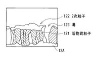
負極活物質層12Bは、例えば、少なくとも一部が気相法により形成されたものであることが好ましい。図2は負極活物質層12Bの厚み方向の断面における粒子構造を表す走査電子顕微鏡(Scanning Electron Microscope;SEM)写真であり、図3はその粒子構造を模式的に表したものである。負極活物質層12Bは、例えば、厚み方向に成長することにより形成され、構成元素としてケイ素を含む複数の活物質粒子121を有している。活物質粒子121の少なくとも一部は、粒子中に上述したフッ化物を含有していることが好ましい。より高い効果を得ることができるからである。また、活物質粒子121は、複数が集合することにより複数の2次粒子122を形成している。各2次粒子122において各活物質粒子121は単に隣接しているのではなく、互いに少なくとも一部が接合している。各2次粒子122は例えば充放電により形成されたものであり、溝123により互いに分離されている。溝123はほぼ負極集電体12Aまで達している。
The anode
負極活物質層12Bは、また、負極集電体12Aと界面の少なくとも一部において合金化していることが好ましい。具体的には、負極集電体12Aの構成元素が負極活物質層12Bに、または負極活物質層12Bの構成元素が負極集電体12Aに、またはそれらが互いに拡散していることが好ましい。充放電により負極活物質層12Bが膨張収縮しても、負極集電体12Aからの脱落を抑制することができるからである。
The negative electrode
正極14は、例えば、正極集電体14Aと、正極集電体14Aに設けられた正極活物質層14Bとを有しており、正極活物質層14Bの側が負極活物質層12Bと対向するように配置されている。正極集電体14Aは、例えば、アルミニウム,ニッケルあるいはステンレスなどにより構成されている。
The
正極活物質層14Bは、例えば、正極活物質としてリチウムを吸蔵および放出することが可能な正極材料のいずれか1種または2種以上を含んでおり、必要に応じて炭素材料などの導電材およびポリフッ化ビニリデンなどのバインダーを含んでいてもよい。リチウムを吸蔵および放出することが可能な正極材料としては、例えば、一般式Lix MO2 で表されるリチウム複合酸化物が好ましい。リチウム複合酸化物は、高電圧を発生可能であると共に、高密度であるため、二次電池の更なる高容量化を図ることができるからである。なお、Mは1種類以上の遷移金属を含み、例えばコバルトおよびニッケルのうちの少なくとも一方を含むことが好ましい。xは電池の充放電状態によって異なり、通常0.05≦x≦1.10の範囲内の値である。このようなリチウム複合酸化物の具体例としては、LiCoO2 あるいはLiNiO2 などが挙げられる。
The positive electrode
セパレータ15は、負極12と正極14とを隔離し、両極の接触による電流の短絡を防止しつつ、リチウムイオンを通過させるものである。このセパレータ15は、例えば、ポリエチレンやポリプロピレンにより構成されている。
The
セパレータ15に含浸されている電解液は、例えば、溶媒と電解質塩とを含んでおり、必要に応じて添加剤を含んでいてもよい。溶媒としては、例えば、炭酸エチレン,炭酸プロピレン,炭酸ジメチル,炭酸ジエチルあるいは炭酸エチルメチルなどの非水溶媒が挙げられる。溶媒はいずれか1種を単独で用いてもよいが、2種以上を混合して用いてもよい。
The electrolyte solution impregnated in the
電解質塩としては、例えば、LiPF6 ,LiCF3 SO3 あるいはLiClO4 などのリチウム塩が挙げられる。電解質塩は、いずれか1種を単独で用いてもよいが、2種以上を混合して用いてもよい。 Examples of the electrolyte salt include lithium salts such as LiPF 6 , LiCF 3 SO 3, and LiClO 4 . Any one electrolyte salt may be used alone, or two or more electrolyte salts may be mixed and used.
この二次電池は、例えば、次のようにして作製することができる。 This secondary battery can be manufactured as follows, for example.
まず、負極集電体12Aに、例えば気相法により構成元素としてケイ素を含む負極活物質層12Bを成膜する。気相法としては、例えば、物理堆積法あるいは化学堆積法が挙げられ、具体的には、真空蒸着法,スパッタ法,イオンプレーティング法,レーザーアブレーション法,CVD(Chemical Vapor Deposition ;化学気相成長)法あるいは溶射法などのいずれを用いてもよい。その際、例えば、ケイ素と共に上述したフッ化物を共蒸着することにより、または、ケイ素を含む層と上述したフッ化物を含む層とを交互に積層することにより、負極活物質層12Bにフッ化物を添加する。
First, the negative electrode
共蒸着する場合は、抵抗加熱方式を用いても電子ビーム方式を用いてもよく、ケイ素の原料とフッ化物の原料とで異なる方式を用いてもよい。ケイ素を含む層とフッ化物を含む層とを交互に積層する場合も、それぞれの成膜方法は同一でも異なっていてもよい。但し、フッ化物を含む層の膜厚分布をより均一とするために、ケイ素の原料の周りにフッ化物の原料を2以上に分けて配置することが好ましい。ケイ素の原料には、例えば、ケイ素単体、ケイ素合金、またはケイ素化合物のいずれを用いてもよく、形成する負極活物質層12Bの組成に応じて選択する。フッ化物の原料には、例えば添加するフッ化物をそのまま用いる。負極活物質層12Bに酸素を添加する場合には、例えば、成膜雰囲気に酸素ガスを導入するようにしてもよい。負極活物質層12Bに鉄、コバルト、ニッケルまたはチタンを添加する場合には、例えば、これらを共蒸着したり、これらを含む層を挿入したり、またはこれらを含むケイ素合金あるいはケイ素化合物を原料に用いてもよい。
In the case of co-evaporation, the resistance heating method or the electron beam method may be used, or different methods may be used for the silicon raw material and the fluoride raw material. Also in the case of alternately laminating silicon-containing layers and fluoride-containing layers, the respective film forming methods may be the same or different. However, in order to make the film thickness distribution of the layer containing fluoride more uniform, it is preferable that the fluoride raw material is divided into two or more around the silicon raw material. For example, any of silicon alone, a silicon alloy, or a silicon compound may be used as a raw material of silicon, and is selected according to the composition of the negative electrode
なお、負極活物質層12Bを成膜したのち、必要に応じて真空雰囲気下または非酸化性雰囲気下で熱処理を行う。負極活物質層12Bを成膜する際に、負極活物質層12Bと負極集電体12Aとが合金化する場合もあるが、熱処理により合金化を促進させることができるからである。特に、ケイ素を含む層とフッ化物を含む層とを交互に積層した場合には、熱処理を行うことによりそれらを相互に拡散させることが好ましい。
Note that after the negative electrode
次いで、正極集電体14Aに正極活物質層14Bを成膜する。例えば、正極活物質と必要に応じて導電材およびバインダーとを混合して正極集電体14Aに塗布し、圧縮成型することにより形成する。続いて、負極12、セパレータ15および正極14を積層して外装カップ11と外装缶13との中に入れ、電解液を注入し、それらをかしめることにより電池を組み立てる。電池を組み立てたのち、例えば充放電を行うことにより、負極活物質層12Bに溝123が形成され、活物質粒子121が複数集合した2次粒子122に分割される。これにより図1に示した二次電池が得られる。
Next, the positive electrode
この二次電池では、充電を行うと、例えば、正極14からリチウムイオンが放出され、電解液を介して負極12に吸蔵される。放電を行うと、例えば、負極12からリチウムイオンが放出され、電解液を介して正極14に吸蔵される。この充放電に伴い、負極活物質層12Bは大きく膨張収縮するが、内部に含まれるフッ化物により膨張が抑制され、応力が緩和される。また、膨張に伴い負極活物質層12Bには新たな面が露出されるが、内部に含まれるフッ化物により被膜の形成が促進され、電解液の分解により堆積される被膜の形成が抑制される。
In the secondary battery, when charged, for example, lithium ions are released from the
このように本実施の形態によれば、負極活物質層12Bの内部に、アルカリ金属のフッ化物およびアルカリ土類金属のフッ化物からなる群のうちの少なくとも1種を含有するようにしたので、負極活物質層12Bの膨張を抑制して内部応力を緩和することができ、負極活物質層12Bの形状崩壊および負極集電体12Aからの剥離を抑制することができる。また、負極活物質層12Bが膨張して新たな面が露出しても、負極活物質層12Bの内部に含まれるフッ化物により被膜の形成を促進し、電解液の分解などにより堆積される新たな被膜の形成を抑制することができる。よって、サイクル特性などの電池特性を向上させることができると共に、電池の膨れを抑制することができる。
As described above, according to the present embodiment, the anode
特に、負極活物質層12Bにおけるアルカリ金属のフッ化物の含有量を、アルカリ金属とフッ素との合計の存在比率で、1原子数%以上40原子数%以下の範囲内とするようにすれば、または、負極活物質層12Bにおけるアルカリ土類金属のフッ化物の含有量を、アルカリ土類金属とフッ素との合計の存在比率で、0.5原子数%以上30原子数%以下の範囲内とするようにすれば、より高い効果を得ることができる。
In particular, if the content of alkali metal fluoride in the negative electrode
また、負極活物質層12Bに酸素を3原子数%以上40原子数%以下の範囲内で含むようにすれば、または、負極活物質層12Bに酸素の含有量が異なる第1層と第2層とを交互に積層して有するようにすれば、負極活物質層12Bの膨張をより抑制することができる。
Further, if the negative electrode
更に、負極活物質層12Bに鉄、コバルト、ニッケルおよびチタンからなる群のうちの少なくとも1種の金属元素を含有するようにすれば、フッ化物の添加による抵抗の上昇を抑制することができる。
Furthermore, if the negative electrode
(第2の実施の形態)
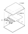
図4は、本発明の第2の実施の形態に係る二次電池の構成を表すものである。この二次電池は、リード21,22が取り付けられた電極巻回体20をフィルム状の外装部材30の内部に収容したものであり、小型化,軽量化および薄型化が可能となっている。
(Second Embodiment)
FIG. 4 shows the configuration of the secondary battery according to the second embodiment of the present invention. In this secondary battery, the
リード21,22は、外装部材30の内部から外部に向かい例えば同一方向にそれぞれ導出されている。リード21,22は、例えば、アルミニウム,銅,ニッケルあるいはステンレスなどの金属材料によりそれぞれ構成されており、それぞれ薄板状または網目状とされている。
The leads 21 and 22 are led out, for example, in the same direction from the inside of the
外装部材30は、例えば、ナイロンフィルム,アルミニウム箔およびポリエチレンフィルムをこの順に貼り合わせた矩形状のアルミラミネートフィルムにより構成されている。外装部材30は、例えば、ポリエチレンフィルム側と電極巻回体20とが対向するように配設されており、各外縁部が融着あるいは接着剤により互いに密着されている。外装部材30とリード21,22との間には、外気の侵入を防止するための密着フィルム31が挿入されている。密着フィルム31は、リード21,22に対して密着性を有する材料、例えば、ポリエチレン,ポリプロピレン,変性ポリエチレンあるいは変性ポリプロピレンなどのポリオレフィン樹脂により構成されている。
The
なお、外装部材30は、上述したアルミラミネートフィルムに代えて、他の構造を有するラミネートフィルム,ポリプロピレンなどの高分子フィルムあるいは金属フィルムにより構成するようにしてもよい。
The
図5は、図4に示した電極巻回体20のI−I線に沿った断面構造を表すものである。電極巻回体20は、負極23と正極24とをセパレータ25および電解質層26を介して積層し、巻回したものであり、最外周部は保護テープ27により保護されている。
FIG. 5 shows a cross-sectional structure taken along line II of the
負極23は、負極集電体23Aの両面に負極活物質層23Bが設けられた構造を有している。正極24も、正極集電体24Aの両面に正極活物質層24Bが設けられた構造を有しており、正極活物質層24Bが負極活物質層23Bと対向するように配置されている。負極集電体23A,負極活物質層23B,正極集電体24A,正極活物質層24Bおよびセパレータ25の構成は、それぞれ上述した負極集電体12A,負極活物質層12B,正極集電体14A,正極活物質層14Bおよびセパレータ15と同様である。なお、負極活物質層23Bの粒子構造は、例えば、電極巻回体20のうち曲率の大きくない部分の中央部において判断する。
The
電解質層26は、高分子化合物よりなる保持体に電解液を保持させたいわゆるゲル状の電解質により構成されている。ゲル状の電解質は高いイオン伝導率を得ることができると共に、電池の漏液を防止することができるので好ましい。電解液の構成は、第1の実施の形態と同様である。高分子材料としては、例えばポリフッ化ビニリデンが挙げられる。
The
この二次電池は、例えば、次のようにして製造することができる。 For example, the secondary battery can be manufactured as follows.
まず、第1の実施の形態と同様にして負極23および正極24を形成したのち、負極23および正極24に、電解液を保持体に保持させた電解質層26を形成する。次いで、負極集電体23Aおよび正極集電体24Aにリード21,22を取り付ける。続いて、電解質層26が形成された負極23と正極24とをセパレータ25を介して積層し、巻回して、最外周部に保護テープ27を接着して電極巻回体20を形成する。そののち、例えば、外装部材30の間に電極巻回体20を挟み込み、外装部材30の外縁部同士を熱融着などにより密着させて封入する。その際、リード21,22と外装部材30との間には密着フィルム31を挿入する。
First, after forming the
また、次のようにして組み立ててもよい。まず、第1の実施の形態と同様にして負極23および正極24を形成したのち、リード21,22を取り付ける。次いで、負極23と正極24とをセパレータ25を介して積層して巻回し、最外周部に保護テープ27を接着して、電極巻回体20の前駆体である巻回体を形成する。続いて、この巻回体を外装部材30に挟み、一辺を除く外周縁部を熱融着して袋状としたのち、電解液と、高分子化合物の原料であるモノマーと、重合開始剤と、必要に応じて重合禁止剤などの他の材料とを含む電解質用組成物を、外装部材30の内部に注入する。そののち、外装部材30の開口部を真空雰囲気下で熱融着して密封し、熱を加えてモノマーを重合させて高分子化合物とすることによりゲル状の電解質層26を形成する。
Moreover, you may assemble as follows. First, after forming the
このようにして電池を組み立てたのち、第1の実施の形態と同様に、例えば充放電を行うことにより、負極活物質層23Bに溝123および2次粒子122が形成される。 After assembling the battery in this manner, the grooves 123 and the secondary particles 122 are formed in the negative electrode active material layer 23B by, for example, charging and discharging, as in the first embodiment.
この二次電池は、第1の実施の形態と同様に作用し、第1の実施の形態と同様の効果を有する。 This secondary battery operates in the same manner as in the first embodiment, and has the same effect as in the first embodiment.
更に、本発明の具体的な実施例について図面を参照して詳細に説明する。 Further, specific embodiments of the present invention will be described in detail with reference to the drawings.
(実施例1−1〜1−11)
図4,5に示した構造の二次電池を作製した。まず、厚み12μmの表面を粗化した銅箔よりなる負極集電体23Aに、真空蒸着法によりケイ素とアルカリ金属のフッ化物とを共蒸着させ、厚み約5μmの負極活物質層23Bを成膜した。その際、アルカリ金属のフッ化物には、実施例1−1〜1−5ではフッ化リチウムを用い、実施例1−6〜1−8ではフッ化ナトリウムを用い、実施例1−9〜1−11ではフッ化カリウムを用いた。また、実施例1−1〜1−11でフッ化物の蒸着量を調節し、負極活物質層23Bにおけるフッ化物の含有量を変化させた。次いで、減圧雰囲気において熱処理を行った。
(Examples 1-1 to 1-11)
A secondary battery having the structure shown in FIGS. First, a negative electrode current collector 23A made of a copper foil having a roughened surface having a thickness of 12 μm is co-deposited with silicon and an alkali metal fluoride by a vacuum deposition method to form a negative electrode active material layer 23B having a thickness of about 5 μm. did. At that time, as the alkali metal fluoride, lithium fluoride was used in Examples 1-1 to 1-5, sodium fluoride was used in Examples 1-6 to 1-8, and Examples 1-9 to 1 were used. In -11, potassium fluoride was used. Moreover, the vapor deposition amount of fluoride was adjusted in Examples 1-1 to 1-11, and the content of fluoride in the negative electrode active material layer 23B was changed. Next, heat treatment was performed in a reduced pressure atmosphere.
作製した実施例1−1〜1−11の負極23について、厚み方向の断面を集束イオンビーム(FIB;Focused Ion Beam)により切り出し、SEMにより観察したところ、いずれについても、複数の活物質粒子121が厚み方向に成長していることが確認された。また、切り出した断面についてAES( Auger Electron Spectroscopy;オージェ電子分光法)により局所元素分析を行ったところ、いずれについても、負極活物質層23Bと負極集電体23Aとが少なくとも一部において合金化していることが確認された。更に、切り出した断面についてAESによるライン分析およびESCA(electron spectroscopy for chemical analysis )による分析を行ったところ、負極活物質層23の内部にアルカリ金属のフッ化物が存在していることが確認された。加えて、この分析により負極活物質層23におけるフッ化物の含有量を調べた。得られた結果を表1および図6に示す。図6は実施例1−1および実施例1−2におけるESCAによるアルカリ金属とフッ素との合計の含有量の分析結果である。
About the produced
また、正極活物質である平均粒径5μmのコバルト酸リチウム(LiCoO2 )粉末92質量部と、導電材であるカーボンブラック3質量部と、バインダーであるポリフッ化ビニリデン5質量部とを混合し、これを分散媒であるN−メチル−2−ピロリドンに投入してスラリーとした。次いで、これを厚み15μmのアルミニウム箔よりなる正極集電体24Aに塗布して乾燥させたのちプレスを行って正極活物質層24Bを形成した。
Also, 92 parts by mass of lithium cobaltate (LiCoO 2 ) powder having an average particle diameter of 5 μm as a positive electrode active material, 3 parts by mass of carbon black as a conductive material, and 5 parts by mass of polyvinylidene fluoride as a binder are mixed. This was put into N-methyl-2-pyrrolidone as a dispersion medium to form a slurry. Next, this was applied to a positive electrode
続いて、炭酸エチレン37.5質量%と、炭酸プロピレン37.5質量%と、炭酸ビニレン10質量%と、LiPF6 15質量%とを混合して電解液を調整し、この電解液30質量部と、重量平均分子量60万のブロック共重合体であるポリフッ化ビニリデン10質量部とを混合し、負極23および正極24の両面にそれぞれ塗布して電解質層26を形成した。そののち、リード21,22を取り付け、負極23と正極24とをセパレータ25を介して積層して巻回し、アルミラミネートフィルムよりなる外装部材30に封入することにより二次電池を組み立てた。
Subsequently, 37.5% by mass of ethylene carbonate, 37.5% by mass of propylene carbonate, 10% by mass of vinylene carbonate, and 15% by mass of LiPF 6 were prepared to prepare an electrolyte solution, and 30 parts by mass of this electrolyte solution And 10 parts by mass of polyvinylidene fluoride, which is a block copolymer having a weight average molecular weight of 600,000, were applied to both surfaces of the
実施例1−1〜1−11に対する比較例1−1として、負極活物質層を成膜する際にフッ化物を共蒸着させなかったことを除き、他は実施例1−1〜1−11と同様にして二次電池を組み立てた。また、比較例1−2〜1−4として、負極活物質層を成膜する際にフッ化物を共蒸着させず、負極活物質層の表面に真空蒸着法によりフッ化リチウム層を成膜したことを除き、他は実施例1−1〜1−11と同様にして二次電池を組み立てた。フッ化リチウム層の厚みは、比較例1−2が130nm、比較例1−3が350nm、比較例1−4が640nmと変化させた。 As Comparative Example 1-1 with respect to Examples 1-1 to 1-11, except that fluoride was not co-deposited when forming the negative electrode active material layer, the other examples were 1-1 to 1-11. A secondary battery was assembled in the same manner as described above. Further, as Comparative Examples 1-2 to 1-4, a lithium fluoride layer was formed on the surface of the negative electrode active material layer by vacuum deposition without co-evaporating fluoride when forming the negative electrode active material layer. Except for this, secondary batteries were assembled in the same manner as in Examples 1-1 to 1-11. The thickness of the lithium fluoride layer was changed to 130 nm in Comparative Example 1-2, 350 nm in Comparative Example 1-3, and 640 nm in Comparative Example 1-4.
作製した実施例1−1〜1−11および比較例1−1〜1−4の二次電池について、25℃の条件下で充放電試験を行い、2サイクル目に対する31サイクル目の容量維持率を求めた。その際、充電は、1mA/cm2 の定電流密度で電池電圧が4.2Vに達するまで行ったのち、4.2Vの定電圧で電流密度が0.05mA/cm2 に達するまで行い、放電は、1mA/cm2 の定電流密度で電池電圧が2.5Vに達するまで行った。なお、充電を行う際には、負極23の容量の利用率が85%となるようにし、負極23に金属リチウムが析出しないようにした。容量維持率は、2サイクル目の放電容量に対する31サイクル目の放電容量の比率、すなわち(31サイクル目の放電容量/2サイクル目の放電容量)×100として算出した。
For the fabricated secondary batteries of Examples 1-1 to 1-11 and Comparative Examples 1-1 to 1-4, a charge / discharge test was performed under the condition of 25 ° C., and the capacity retention rate of the 31st cycle with respect to the 2nd cycle Asked. At that time, charging is performed at a constant current density of 1 mA / cm 2 until the battery voltage reaches 4.2 V, and then at a constant voltage of 4.2 V until the current density reaches 0.05 mA / cm 2. Was performed at a constant current density of 1 mA / cm 2 until the battery voltage reached 2.5V. When charging, the capacity utilization of the
また、作製した実施例1−1〜1−11および比較例1−1〜1−4の二次電池について、充放電を行う前と、31サイクル充放電を行った後とで電池の厚みを測定し、31サイクル後の膨張率を調べた。膨張率は、充放電前の厚みに対する31サイクル後の厚みの割合、すなわち31サイクル後の厚み/充放電前の厚みにより算出した。得られた結果を表1に示す。 Moreover, about the produced secondary battery of Examples 1-1 to 1-11 and Comparative Examples 1-1 to 1-4, before charging / discharging and after performing 31 cycle charging / discharging, the thickness of a battery is set. Measured and examined the expansion rate after 31 cycles. The expansion coefficient was calculated by the ratio of the thickness after 31 cycles to the thickness before charge / discharge, that is, the thickness after 31 cycles / thickness before charge / discharge. The obtained results are shown in Table 1.
更に、実施例1−1〜1−11の二次電池について、31サイクル後に電池を解体して放電状態の負極23を取り出し、負極23の中央部における厚み方向の断面をSEMにより観察したところ、いずれについても、図2,3に示したように複数の活物質粒子121が集合して2次粒子122を形成していることが確認された。
Further, for the secondary batteries of Examples 1-1 to 1-11, the battery was disassembled after 31 cycles, the discharged

表1に示したように、実施例1−1〜1−11によれば、比較例1−1〜1−4に比べて容量維持率が向上し、膨れも小さくなった。すなわち、負極活物質層23Bの内部にアルカリ金属のフッ化物を含有するようにすれば、充放電による内部応力を緩和して、サイクル特性などの電池特性を向上させることができると共に、電池の膨れも抑制することができることが分かった。 As shown in Table 1, according to Examples 1-1 to 1-11, the capacity retention rate was improved and swelling was also reduced as compared with Comparative Examples 1-1 to 1-4. That is, if an alkali metal fluoride is contained in the negative electrode active material layer 23B, the internal stress due to charge / discharge can be relieved to improve battery characteristics such as cycle characteristics, and the battery swells. It was also found that it can be suppressed.
また、実施例1−1〜1−11の結果をみると、フッ化物の含有量を増加させると膨張率はより小さくなるものの、容量維持率は増加したのち低下する傾向がみられた。すなわち、負極活物質層23Bにおけるアルカリ金属のフッ化物の含有量は、アルカリ金属とフッ素との合計の存在比率で、1原子数%以上40原子数%以下の範囲内が好ましいことが分かった。 Moreover, when the result of Examples 1-1 to 1-11 was seen, when the content of fluoride was increased, the expansion rate decreased, but the capacity retention rate tended to decrease after increasing. That is, it was found that the content of alkali metal fluoride in the negative electrode active material layer 23B is preferably in the range of 1 atomic% to 40 atomic% in terms of the total abundance ratio of alkali metal and fluorine.
(実施例2−1〜2−14)
負極活物質層23Bを成膜する際に、アルカリ金属のフッ化物に代えて、アルカリ土類金属のフッ化物を共蒸着させたことを除き、他は実施例1−1〜1−11と同様にして二次電池を組み立てた。アルカリ土類金属のフッ化物には、実施例2−1〜2−4ではフッ化マグネシウムを用い、実施例2−5〜2−7ではフッ化カルシウムを用い、実施例2−8,2−9ではフッ化ストロンチウムを用い、実施例2−10〜2−14ではフッ化バリウムを用いた。また、実施例2−1〜2−14でフッ化物の蒸着量を調節し、負極活物質層23Bにおけるフッ化物の含有量を変化させた。
(Examples 2-1 to 2-14)
Except that the alkaline earth metal fluoride was co-deposited instead of the alkali metal fluoride when forming the negative electrode active material layer 23B, the others were the same as in Examples 1-1 to 1-11 Then, a secondary battery was assembled. As the alkaline earth metal fluoride, magnesium fluoride is used in Examples 2-1 to 2-4, calcium fluoride is used in Examples 2-5 to 2-7, and Examples 2-8 and 2- In Example 9, strontium fluoride was used, and in Examples 2-10 to 2-14, barium fluoride was used. Moreover, the vapor deposition amount of fluoride was adjusted in Examples 2-1 to 2-14, and the content of fluoride in the negative electrode active material layer 23B was changed.
作製した実施例2−1〜2−14の負極23についても、実施例1−1〜1−11と同様に、厚み方向の断面を切り出してSEM、AESおよびESCAにより分析を行った。その結果、実施例2−1〜2−14の負極23についても、複数の活物質粒子121が厚み方向に成長しており、負極活物質層23Bと負極集電体23Aとが少なくとも一部において合金化していることが確認された。また、負極活物質層23の内部にアルカリ土類金属のフッ化物が存在していることが確認された。負極活物質層23におけるフッ化物の含有量の分析結果を表2および図7に示す。図7は実施例2−12におけるESCAによるバリウムおよびフッ素の含有量の分析結果である。
For the produced
また、本実施例に対する比較例2−1〜2−5として、負極活物質層を成膜する際にフッ化物を共蒸着させず、負極活物質層の表面に真空蒸着法によりフッ化マグネシウム層またはフッ化バリウム層を成膜したことを除き、他は実施例2−1〜2−14と同様にして二次電池を組み立てた。その際、比較例2−1,2−2ではフッ化マグネシウム層を成膜し、フッ化マグネシウム層の厚みは、比較例2−1が200nm、比較例2−2が640nmとした。比較例2−3〜2−5ではフッ化バリウム層を成膜し、フッ化バリウム層の厚みは、比較例2−3が350nm、比較例2−4が500nm、比較例2−5が720nmとした。 In addition, as Comparative Examples 2-1 to 2-5 with respect to the present embodiment, a magnesium fluoride layer is not formed on the surface of the negative electrode active material layer by vacuum deposition without co-depositing fluoride when forming the negative electrode active material layer. Alternatively, a secondary battery was assembled in the same manner as in Examples 2-1 to 2-14 except that a barium fluoride layer was formed. At that time, in Comparative Examples 2-1 and 2-2, a magnesium fluoride layer was formed, and the thickness of the magnesium fluoride layer was 200 nm in Comparative Example 2-1 and 640 nm in Comparative Example 2-2. In Comparative Examples 2-3 to 2-5, a barium fluoride layer was formed. The thickness of the barium fluoride layer was 350 nm in Comparative Example 2-3, 500 nm in Comparative Example 2-4, and 720 nm in Comparative Example 2-5. It was.
作製した実施例2−1〜2−14および比較例2−1〜2−5の二次電池についても、実施例1−1〜1−11と同様にして充放電を行い、容量維持率および電池の膨張率を調べた。得られた結果を比較例1−1の結果と共に表2に示す。また、実施例1−1〜1−11と同様にして31サイクル後に負極23の状態を観察したところ、いずれについても、図2,3に示したように複数の活物質粒子121が集合して2次粒子122を形成していることが確認された。
For the fabricated secondary batteries of Examples 2-1 to 2-14 and Comparative Examples 2-1 to 2-5, charging and discharging were performed in the same manner as in Examples 1-1 to 1-11, and the capacity retention rate and The expansion coefficient of the battery was examined. The obtained results are shown in Table 2 together with the results of Comparative Example 1-1. Further, when the state of the
表2に示したように、実施例2−1〜2−14によれば、比較例1−1,2−1〜2−5に比べて容量維持率が向上し、膨れも小さくなった。すなわち、負極活物質層23Bの内部にアルカリ土類金属のフッ化物を含有するようにしても、充放電による内部応力を緩和して、サイクル特性などの電池特性を向上させることができると共に、電池の膨れも抑制することができることが分かった。 As shown in Table 2, according to Examples 2-1 to 2-14, the capacity retention rate was improved and the swelling was reduced as compared with Comparative Examples 1-1 and 2-1 to 2-5. That is, even if the negative electrode active material layer 23B contains an alkaline earth metal fluoride, the internal stress due to charge / discharge can be relieved to improve battery characteristics such as cycle characteristics, and the battery. It was found that blistering can be suppressed.
また、実施例2−1〜2−14の結果をみると、フッ化物の含有量を増加させると膨張率はより小さくなるものの、容量維持率は増加したのち低下する傾向がみられた。すなわち、負極活物質層23Bにおけるアルカリ土類金属のフッ化物の含有量は、アルカリ土類金属とフッ素との合計の存在比率で、0.5原子数%以上30原子数%以下の範囲内が好ましいことが分かった。 Moreover, when the result of Examples 2-1 to 2-14 was seen, when the content of fluoride was increased, the expansion rate became smaller, but the capacity retention rate tended to decrease after increasing. That is, the content of the alkaline earth metal fluoride in the negative electrode active material layer 23B is in the range of 0.5 atomic% to 30 atomic% in terms of the total abundance ratio of the alkaline earth metal and fluorine. It turned out to be preferable.
(実施例3−1〜3−6)
負極活物質層23Bを成膜する際に、フッ化物を共蒸着せずに、ケイ素の層とフッ化物の層とを交互に積層したことを除き、他は実施例1−1〜1−11と同様にして二次電池を組み立てた。実施例3−1〜3−3ではフッ化物にフッ化リチウムを用い、フッ化物層はスパッタリング法により成膜した。実施例3−4〜3−6ではフッ化物にフッ化バリウムを用い、フッ化物層は真空蒸着法により成膜した。なお、ケイ素の層はいずれも真空蒸着法により成膜した。
(Examples 3-1 to 3-6)
Except that the negative electrode active material layer 23B was formed, the silicon layer and the fluoride layer were alternately laminated without co-evaporating the fluoride. A secondary battery was assembled in the same manner as described above. In Examples 3-1 to 3-3, lithium fluoride was used as the fluoride, and the fluoride layer was formed by a sputtering method. In Examples 3-4 to 3-6, barium fluoride was used as the fluoride, and the fluoride layer was formed by vacuum deposition. All silicon layers were formed by vacuum deposition.
具体的には、
実施例3−1では、厚み1μmのケイ素の層と、厚み100nmのフッ化リチウムの層とを交互に4層ずつ成膜し、最後に厚み1μmのケイ素の層を成膜した。実施例3−2では、厚み2μmのケイ素の層と、厚み200nmのフッ化リチウムの層とを交互に2層ずつ成膜し、最後に厚み1μmのケイ素の層を成膜した。実施例3−3では、厚み0.5μmのケイ素の層と、厚み50nmのフッ化リチウムの層とを交互に8層ずつ成膜し、最後に厚み1μmのケイ素の層を成膜した。実施例3−4では、厚み1μmのケイ素の層と、厚み100nmのフッ化バリウムの層とを交互に4層ずつ成膜し、最後に厚み1μmのケイ素の層を成膜した。実施例3−5では、厚み2μmのケイ素の層と、厚み200nmのフッ化バリウムの層とを交互に2層ずつ成膜し、最後に厚み1μmのケイ素の層を成膜した。実施例3−6では、厚み0.5μmのケイ素の層と、厚み50nmのフッ化バリウムの層とを交互に8層ずつ成膜し、最後に厚み1μmのケイ素の層を成膜した。
In particular,
In Example 3-1, four silicon layers having a thickness of 1 μm and four layers of lithium fluoride having a thickness of 100 nm were alternately formed, and finally a silicon layer having a thickness of 1 μm was formed. In Example 3-2, two silicon layers having a thickness of 2 μm and two lithium fluoride layers having a thickness of 200 nm were alternately formed, and finally a silicon layer having a thickness of 1 μm was formed. In Example 3-3, eight silicon layers each having a thickness of 0.5 μm and five lithium layers having a thickness of 50 nm were alternately formed, and finally a silicon layer having a thickness of 1 μm was formed. In Example 3-4 , four silicon layers having a thickness of 1 μm and four layers of barium fluoride having a thickness of 100 nm were alternately formed, and finally a silicon layer having a thickness of 1 μm was formed. In Example 3-5 , two silicon layers having a thickness of 2 μm and two layers of barium fluoride having a thickness of 200 nm were alternately formed, and finally a silicon layer having a thickness of 1 μm was formed. In Example 3-6, eight layers of 0.5 μm thick silicon layers and 50 nm thick barium fluoride layers were alternately formed, and finally a 1 μm thick silicon layer was formed.
作製した実施例3−1〜3−6の負極23についても、実施例1−1〜1−11と同様に、厚み方向の断面を切り出してSEM、AESおよびESCAにより分析を行った。その結果、実施例3−1〜3−6の負極23についても、複数の活物質粒子121が厚み方向に成長しており、負極活物質層23Bと負極集電体23Aとが少なくとも一部において合金化していることが確認された。また、負極活物質層23の内部にフッ化物が存在していることが確認された。
For the produced
作製した実施例3−1〜3−6の二次電池についても、実施例1−1〜1−11と同様にして充放電を行い、容量維持率および電池の膨張率を調べた。得られた結果を比較例1−1〜1−4,2−3〜2−5の結果と共に表3に示す。また、実施例1−1〜1−11と同様にして31サイクル後に負極23の状態を観察したところ、いずれについても、図2,3に示したように複数の活物質粒子121が集合して2次粒子122を形成していることが確認された。
For the fabricated secondary batteries of Examples 3-1 to 3-6, charge and discharge were performed in the same manner as in Examples 1-1 to 1-11, and the capacity retention ratio and the battery expansion coefficient were examined. The obtained results are shown in Table 3 together with the results of Comparative Examples 1-1 to 1-4 and 2-3 to 2-5. Further, when the state of the
表3に示したように、実施例3−1〜3−6によっても、比較例1−1〜1−4,2−3〜2−5に比べて容量維持率が向上し、膨れも小さくなった。すなわち、負極活物質層23Bの形成方法によらず、負極活物質層23Bの内部にアルカリ金属またはアルカリ土類金属のフッ化物を含有するようにすれば、サイクル特性などの電池特性を向上させることができると共に、電池の膨れを抑制できることが分かった。 As shown in Table 3, according to Examples 3-1 to 3-6, the capacity retention rate is improved and the swelling is small as compared with Comparative Examples 1-1 to 1-4 and 2-3 to 2-5. became. That is, battery characteristics such as cycle characteristics can be improved by containing an alkali metal or alkaline earth metal fluoride inside the anode active material layer 23B regardless of the method of forming the anode active material layer 23B. As a result, it was found that swelling of the battery can be suppressed.
(実施例4−1〜4−10)
負極集電体23Aの表面粗度Ra値を0.1μm〜0.5μmの範囲内で変化させたことを除き、他は実施例1−2または実施例2−6と同様にして二次電池を組み立てた。実施例4−1〜4−5ではフッ化物にフッ化リチウムを用い、実施例4−6〜4−10ではフッ化カルシウムを用いた。作製した実施例4−1〜4−10の負極23についても、実施例1−2,2−6と同様にしてフッ化物の含有量を調べたところ、実施例4−1〜4−5はリチウムとフッ素との合計の存在比率が約6.5原子数%であり、実施例4−6〜4−10はカルシウムとフッ素との合計の存在比率が約15.3原子数%であった。
(Examples 4-1 to 4-10)
The secondary battery was the same as Example 1-2 or Example 2-6 except that the surface roughness Ra value of the negative electrode current collector 23A was changed within the range of 0.1 μm to 0.5 μm. Assembled. In Examples 4-1 to 4-5, lithium fluoride was used as the fluoride, and in Examples 4-6 to 4-10, calcium fluoride was used. For the produced
また、作製した実施例4−1〜4−10の二次電池についても、実施例1−2,2−6と同様にして充放電を行い、容量維持率および電池の膨張率を調べた。得られた結果を表4,5に示す。 In addition, the fabricated secondary batteries of Examples 4-1 to 4-10 were charged and discharged in the same manner as in Examples 1-2 and 2-6, and the capacity retention ratio and the battery expansion coefficient were examined. The obtained results are shown in Tables 4 and 5.
表4,5に示したように、負極集電体23Aの表面粗度Ra値を大きくするに従い、容量維持率は向上する傾向がみられた。すなわち、負極集電体23Aの表面粗度Ra値を0.1μm以上とすれば好ましいことが分かった。 As shown in Tables 4 and 5, the capacity retention ratio tended to improve as the surface roughness Ra value of the negative electrode current collector 23A was increased. That is, it was found that the surface roughness Ra value of the negative electrode current collector 23A is preferably 0.1 μm or more.
(実施例5−1〜5−6,6−1〜6−6)
負極活物質層23Bを成膜する際に、ケイ素とフッ化物とを共蒸着した第1層と、酸化ケイ素の第2層とを交互に積層し、たことを除き、他は実施例1−2または実施例2−6と同様にして二次電池を組み立てた。第2層は、実施例5−1〜5−6では真空蒸着法により成膜し、実施例6−1〜6−6では酸素ガスを導入して第1層の表面を酸化させることにより成膜した。また、実施例5−1〜5−3,6−1〜6−3ではフッ化物にフッ化リチウムを用い、実施例5−4〜5−6,6−4〜6−6ではフッ化物にフッ化カルシウムを用いた。
(Examples 5-1 to 5-6, 6-1 to 6-6)
Except for the fact that when the negative electrode active material layer 23B was formed, the first layer in which silicon and fluoride were co-deposited and the second layer of silicon oxide were alternately laminated, the others were as in Example 1 A secondary battery was assembled in the same manner as in Example 2 or Example 2-6. The second layer is formed by vacuum deposition in Examples 5-1 to 5-6, and in Examples 6-1 to 6-6, oxygen gas is introduced to oxidize the surface of the first layer. Filmed. In Examples 5-1 to 5-3, 6-1 to 6-3, lithium fluoride is used as the fluoride. In Examples 5-4 to 5-6 and 6-4 to 6-6, the fluoride is used. Calcium fluoride was used.
具体的には、実施例5−1,5−4,6−1,6−4では、厚み1μmの第1層と、厚み100nmの第2層とを交互に4層ずつ成膜し、最後に厚み1μmの第1層を成膜した。実施例5−2,5−5では、厚み2μmの第1層と、厚み200nmの第2層とを交互に2層ずつ成膜し、最後に厚み1μmの第1層を成膜した。実施例5−3,5−6では、厚み0.5μmの第1層と、厚み50nmの第2層とを交互に8層ずつ成膜し、最後に厚み1μmの第1層を成膜した。作製した実施例5−1〜5−6,6−1〜6−6の負極23についても、実施例1−2,2−6と同様にしてフッ化物の含有量を調べたところ、実施例5−1〜5−3,6−1〜6−3はリチウムとフッ素との合計の存在比率が約6.5原子数%であり、実施例5−4〜5−6,6−4〜6−6はカルシウムとフッ素との合計の存在比率が約15.3原子数%であった。
Specifically, in Examples 5-1, 5-4, 6-1, and 6-4, four first layers each having a thickness of 1 μm and a second layer having a thickness of 100 nm are alternately formed. A first layer having a thickness of 1 μm was formed. In Examples 5-2 and 5-5, two first layers having a thickness of 2 μm and two second layers having a thickness of 200 nm were alternately formed, and finally, a first layer having a thickness of 1 μm was formed. In Examples 5-3 and 5-6, the first layer having a thickness of 0.5 μm and the second layer having a thickness of 50 nm were alternately formed by 8 layers, and finally the first layer having a thickness of 1 μm was formed. . For the prepared
また、作製した実施例5−1〜5−6,6−1〜6−6の二次電池についても、実施例1−2,2−6と同様にして充放電を行い、容量維持率および電池の膨張率を調べた。得られた結果を実施例1−2,2−6の結果と共に表6,7に示す。 Also, for the fabricated secondary batteries of Examples 5-1 to 5-6 and 6-1 to 6-6, charging and discharging were performed in the same manner as in Examples 1-2 and 2-6, and the capacity retention rate and The expansion coefficient of the battery was examined. The obtained results are shown in Tables 6 and 7 together with the results of Examples 1-2 and 2-6.
表6,7に示したように、実施例5−1〜5−6,6−1〜6−6によれば、実施例1−2,2−6よりも、更に容量維持率が向上し、膨張率は小さくなった。すなわち、負極活物質層23Bに酸素の含有量が多い第2層とを有するようにすれば、より好ましいことが分かった。 As shown in Tables 6 and 7, according to Examples 5-1 to 5-6 and 6-1 to 6-6, the capacity retention rate was further improved compared to Examples 1-2 and 2-6. The expansion rate became smaller. That is, it has been found that it is more preferable if the negative electrode active material layer 23B has the second layer having a high oxygen content.
(実施例7−1〜7−20)
負極活物質層23Bを成膜する際に酸素ガスを連続して導入し、酸素を添加したことを除き、他は実施例1−2または実施例2−6と同様にして二次電池を組み立てた。その際、酸素ガスの導入量を調節し、酸素の含有量を変化させた。なお、実施例7−1〜7−10ではフッ化物にフッ化リチウムを用い、実施例7−11〜7−20ではフッ化物にフッ化カルシウムを用いた。作製した実施例7−1〜7−20の負極23についても、実施例1−2,2−6と同様にしてフッ化物の含有量および酸素の含有量を調べた。その結果、実施例7−1〜7−10はリチウムとフッ素との合計の存在比率が約6.5原子数%であり、実施例7−11〜7−20はカルシウムとフッ素との合計の存在比率が約15.3原子数%であった。また、酸素の含有量は表8に示した通りであった。
(Examples 7-1 to 7-20)
A secondary battery was assembled in the same manner as in Example 1-2 or Example 2-6 except that oxygen gas was continuously introduced when the anode active material layer 23B was formed and oxygen was added. It was. At that time, the amount of oxygen gas introduced was adjusted to change the oxygen content. In Examples 7-1 to 7-10, lithium fluoride was used as the fluoride, and in Examples 7-11 to 7-20, calcium fluoride was used as the fluoride. For the produced
また、作製した実施例7−1〜7−20の二次電池についても、実施例1−2,2−6と同様にして充放電を行い、容量維持率および電池の膨張率を調べた。得られた結果を実施例1−2,2−6の結果と共に表8に示す。 In addition, the fabricated secondary batteries of Examples 7-1 to 7-20 were charged and discharged in the same manner as in Examples 1-2 and 2-6, and the capacity retention ratio and the expansion coefficient of the battery were examined. The obtained results are shown in Table 8 together with the results of Examples 1-2 and 2-6.
表8に示したように、実施例7−1〜7−20によれば、実施例1−2,2−6よりも、更に容量維持率が向上し、膨張率は小さくなった。すなわち、負極活物質層12Bに構成元素として酸素を含むようにすれば、より好ましいことが分かった。また、酸素の含有量を増加させるに従い、膨張率はより小さくなるものの、容量維持率は向上したのち低下する傾向がみられた。すなわち、負極活物質層23Bにおける酸素の含有量は、3原子数%以上40原子数%の範囲内とすることが好ましいことが分かった。
As shown in Table 8, according to Examples 7-1 to 7-20, the capacity retention rate was further improved and the expansion rate was smaller than those of Examples 1-2 and 2-6. That is, it was found that it was more preferable if the negative electrode
(実施例8−1〜8−12)
負極活物質層23Bを成膜する際に酸素ガスを導入して酸素を添加すると共に、鉄,ニッケル,チタンまたはコバルトを共蒸着したことを除き、他は実施例1−2と同様にして二次電池を組み立てた。その際、フッ化物にはフッ化リチウムを用い、酸素ガスの導入量は実施例8−1〜8−12で一定とした。また、金属元素は、実施例8−1〜8−9が鉄、実施例8−10がニッケル、実施例8−11がチタン、実施例8−12がコバルトとし、実施例8−1〜8−9で金属元素の蒸着量を変化させた。作製した実施例8−1〜8−12の負極23についても、実施例1−2と同様にしてフッ化物、酸素および金属元素の含有量を調べた。その結果、リチウムとフッ素との合計の存在比率はいずれも約6.5原子数%であり、酸素の含有量はいずれも約5原子数%であった。また、金属元素の含有量は表9に示した通りであった。
(Examples 8-1 to 8-12)
Except that oxygen gas was introduced and oxygen was added when the anode active material layer 23B was formed, and iron, nickel, titanium, or cobalt was co-evaporated, and the same procedure as in Example 1-2 was performed. The next battery was assembled. At that time, lithium fluoride was used as the fluoride, and the amount of oxygen gas introduced was constant in Examples 8-1 to 8-12. Moreover, Examples 8-1 to 8-9 are iron, Example 8-10 is nickel, Example 8-11 is titanium, Example 8-12 is cobalt, and Examples 8-1 to 8-8 are metal elements. The deposition amount of the metal element was changed at -9. For the produced
また、作製した実施例8−1〜8−12の二次電池についても、実施例1−2と同様にして充放電を行い、容量維持率および電池の膨張率を調べた。得られた結果を実施例1−2および実施例7−4の結果と共に表9に示す。 In addition, the fabricated secondary batteries of Examples 8-1 to 8-12 were charged and discharged in the same manner as in Example 1-2, and the capacity retention rate and the battery expansion rate were examined. The obtained results are shown in Table 9 together with the results of Example 1-2 and Example 7-4.
表9に示したように、実施例8−1〜8−12によれば、実施例1−2,7−4よりも、更に容量維持率が向上し、膨張率は小さくなった。すなわち、負極活物質層23Bに構成元素として鉄、ニッケル、チタンまたはコバルトの金属元素を含むようにすれば、より好ましいことが分かった。 As shown in Table 9, according to Examples 8-1 to 8-12, the capacity retention rate was further improved and the expansion rate was smaller than those of Examples 1-2 and 7-4. That is, it has been found that it is more preferable that the negative electrode active material layer 23B contains a metal element of iron, nickel, titanium, or cobalt as a constituent element.
以上、実施の形態および実施例を挙げて本発明を説明したが、本発明は上記実施の形態および実施例に限定されるものではなく、種々変形可能である。例えば、上記実施の形態および実施例では、液状の電解質である電解液、またはいわゆるゲル状の電解質を用いる場合について説明したが、他の電解質を用いるようにしてもよい。他の電解質としては、イオン伝導性を有する固体電解質、固体電解質と電解液とを混合したもの、あるいは固体電解質とゲル状の電解質とを混合したものが挙げられる。 Although the present invention has been described with reference to the embodiments and examples, the present invention is not limited to the above embodiments and examples, and various modifications can be made. For example, in the above-described embodiments and examples, the case where an electrolytic solution which is a liquid electrolyte or a so-called gel electrolyte is used has been described, but another electrolyte may be used. Examples of other electrolytes include solid electrolytes having ionic conductivity, a mixture of a solid electrolyte and an electrolyte solution, and a mixture of a solid electrolyte and a gel electrolyte.
なお、固体電解質には、例えば、イオン伝導性を有する高分子化合物に電解質塩を分散させた高分子固体電解質、またはイオン伝導性ガラスあるいはイオン性結晶などよりなる無機固体電解質を用いることができる。高分子固体電解質の高分子化合物としては、例えば、ポリエチレンオキサイドあるいはポリエチレンオキサイドを含む架橋体などのエーテル系高分子化合物、ポリメタクリレートなどのエステル系高分子化合物、アクリレート系高分子化合物を単独あるいは混合して、または共重合させて用いることができる。また、無機固体電解質としては、窒化リチウムあるいはリン酸リチウムなどを含むもの用いることができる。 As the solid electrolyte, for example, a polymer solid electrolyte in which an electrolyte salt is dispersed in a polymer compound having ion conductivity, or an inorganic solid electrolyte made of ion conductive glass or ionic crystals can be used. Examples of the polymer compound of the solid polymer electrolyte include, for example, an ether polymer compound such as polyethylene oxide or a crosslinked product containing polyethylene oxide, an ester polymer compound such as polymethacrylate, and an acrylate polymer compound. Or can be copolymerized. In addition, as the inorganic solid electrolyte, one containing lithium nitride or lithium phosphate can be used.
また、上記実施の形態および実施例では、コイン型および巻回ラミネート型の二次電池について説明したが、本発明は、円筒型,角型,ボタン型,薄型,大型あるいは積層ラミネート型などの他の形状を有する二次電池についても同様に適用することができる。加えて、二次電池に限らず、一次電池についても適用することができる。 In the above embodiments and examples, the coin type and wound laminate type secondary batteries have been described. However, the present invention is not limited to a cylindrical type, a square type, a button type, a thin type, a large size, or a laminated laminate type. The present invention can be similarly applied to a secondary battery having the shape. In addition, the present invention can be applied not only to secondary batteries but also to primary batteries.
11…外装カップ、12,23…負極、12A,23A…負極集電体、12B,23B…負極活物質層、13…外装缶、14,24…正極、14A,24A…正極集電体、14B,24B…正極活物質層、15,25…セパレータ、16…ガスケット、20…電極巻回体、21,22…リード、26…電解質層、27…保護テープ、30…外装部材、31…密着フィルム、121…活物質粒子、122…2次粒子、123…溝
DESCRIPTION OF
Claims (23)
前記負極活物質層は、その少なくとも一部が気相法により形成されたものであり、かつ、内部に、アルカリ金属のフッ化物およびアルカリ土類金属のフッ化物からなる群のうちの少なくとも1種を含有する
負極。 A negative electrode comprising a negative electrode current collector and a negative electrode active material layer containing silicon (Si) as a constituent element,
The negative electrode active material layer is formed at least in part by a vapor phase method, and has at least one member selected from the group consisting of alkali metal fluorides and alkaline earth metal fluorides therein. Containing negative electrode.
前記負極活物質層におけるアルカリ金属のフッ化物の含有量は、前記負極活物質層の全ての構成元素に対するアルカリ金属とフッ素との合計の存在比率で、1原子数%以上40原子数%以下の範囲内である請求項1記載の負極。 The negative electrode active material layer is formed only by a vapor phase method,
The content of the alkali metal fluoride in the negative electrode active material layer is a total abundance ratio of alkali metal and fluorine with respect to all the constituent elements of the negative electrode active material layer, and ranges from 1 atomic% to 40 atomic%. The negative electrode according to claim 1, which is within a range.
前記負極活物質層におけるアルカリ土類金属のフッ化物の含有量は、前記負極活物質層の全ての構成元素に対するアルカリ土類金属とフッ素との合計の存在比率で、0.5原子数%以上30原子数%以下の範囲内である請求項1記載の負極。 The negative electrode active material layer is formed only by a vapor phase method,
The content of the fluoride of the alkaline earth metal in the negative electrode active material layer is a total abundance ratio of the alkaline earth metal and fluorine with respect to all the constituent elements of the negative electrode active material layer, and 0.5 atomic% or more The negative electrode according to claim 1, which is within a range of 30 atomic% or less.
前記負極活物質層は、更に構成元素として酸素(O)を含有し、その含有量は前記負極活物質層の全ての構成元素に対して3原子数%以上40原子数%以下である
請求項1から請求項6のいずれか1項に記載の負極。 The negative electrode active material layer is formed only by a vapor phase method,
The negative electrode active material layer further contains oxygen (O) as a constituent element, and the content thereof is 3 atomic% to 40 atomic% with respect to all the constituent elements of the negative electrode active material layer. The negative electrode according to any one of claims 1 to 6 .
前記第2層は前記第1層よりも酸素の含有量が多く、かつ、少なくとも前記第1層の間に1層以上存在する
請求項1から請求項7のいずれか1項に記載の負極。 The negative electrode active material layer contains oxygen as a constituent element, and has first and second layers alternately stacked with different oxygen contents,
The negative electrode according to any one of claims 1 to 7 , wherein the second layer has a higher oxygen content than the first layer, and at least one layer exists between the first layers.
前記負極活物質層における前記金属の含有量は、前記負極活物質層の全ての構成元素に対して0.5原子数%以上30原子数%以下である請求項9記載の負極。 The negative electrode active material layer is formed only by a vapor phase method,
The negative electrode according to claim 9, wherein a content of the metal in the negative electrode active material layer is 0.5 atomic% to 30 atomic% with respect to all constituent elements of the negative electrode active material layer.
前記負極は、負極集電体と、構成元素としてケイ素(Si)を含む負極活物質層とを有し、
前記負極活物質層は、その少なくとも一部が気相法により形成されたものであり、かつ、内部に、アルカリ金属のフッ化物およびアルカリ土類金属のフッ化物からなる群のうちの少なくとも1種を含有する
電池。 A battery comprising an electrolyte together with a positive electrode and a negative electrode,
The negative electrode has a negative electrode current collector and a negative electrode active material layer containing silicon (Si) as a constituent element,
The negative electrode active material layer is formed at least in part by a vapor phase method, and has at least one member selected from the group consisting of alkali metal fluorides and alkaline earth metal fluorides therein. Containing batteries.
前記負極活物質層におけるアルカリ金属のフッ化物の含有量は、前記負極活物質層の全ての構成元素に対するアルカリ金属とフッ素との合計の存在比率で、1原子数%以上40原子数%以下の範囲内である請求項12記載の電池。 The negative electrode active material layer is formed only by a vapor phase method,
The content of the alkali metal fluoride in the negative electrode active material layer is a total abundance ratio of alkali metal and fluorine with respect to all the constituent elements of the negative electrode active material layer, and ranges from 1 atomic% to 40 atomic%. The battery according to claim 12, which is within a range.
前記負極活物質層におけるアルカリ土類金属のフッ化物の含有量は、前記負極活物質層の全ての構成元素に対するアルカリ土類金属とフッ素との合計の存在比率で、0.5原子数%以上30原子数%以下の範囲内である請求項12記載の電池。 The negative electrode active material layer is formed only by a vapor phase method,
The content of the fluoride of the alkaline earth metal in the negative electrode active material layer is a total abundance ratio of the alkaline earth metal and fluorine with respect to all the constituent elements of the negative electrode active material layer, and 0.5 atomic% or more The battery according to claim 12, which is within a range of 30 atomic% or less.
複数の前記二次粒子は、前記負極集電体上において溝により互いに分離して配置されている
請求項16記載の電池。 The negative electrode active material layer has a plurality of secondary particles formed by aggregating a plurality of the active material particles and joining at least a part of each other,
The battery according to claim 16, wherein the plurality of secondary particles are separated from each other by a groove on the negative electrode current collector.
前記負極活物質層は、更に構成元素として酸素(O)を含有し、その含有量は前記負極活物質層の全ての構成元素に対して3原子数%以上40原子数%以下である請求項12から請求項18のいずれか1項に記載の電池。 The negative electrode active material layer is formed only by a vapor phase method,
The negative electrode active material layer further contains oxygen (O) as a constituent element, and the content thereof is 3 atomic% to 40 atomic% with respect to all the constituent elements of the negative electrode active material layer. The battery according to any one of claims 12 to 18.
前記第2層は前記第1層よりも酸素の含有量が多く、かつ、少なくとも前記第1層の間に1層以上存在する
請求項12から請求項19のいずれか1項に記載の電池。 The negative electrode active material layer contains oxygen as a constituent element, and has first and second layers alternately stacked with different oxygen contents,
The battery according to any one of claims 12 to 19, wherein the second layer has a higher oxygen content than the first layer, and at least one layer exists between the first layers.
前記負極活物質層における前記金属の含有量は、前記負極活物質層の全ての構成元素に対して0.5原子数%以上30原子数%以下である請求項21記載の電池。 The negative electrode active material layer is formed only by a vapor phase method,
The battery according to claim 21, wherein the content of the metal in the negative electrode active material layer is 0.5 atomic percent or more and 30 atomic percent or less with respect to all the constituent elements of the negative electrode active material layer.
The battery according to any one of claims 12 to 22, wherein the negative electrode current collector has a surface roughness Ra of 0.1 µm or more.
Priority Applications (6)
| Application Number | Priority Date | Filing Date | Title |
|---|---|---|---|
| JP2006077073A JP4655976B2 (en) | 2006-03-20 | 2006-03-20 | Negative electrode and battery |
| US11/684,880 US9112238B2 (en) | 2006-03-20 | 2007-03-12 | Anode and battery |
| KR1020070026531A KR101384429B1 (en) | 2006-03-20 | 2007-03-19 | Anode and battery |
| CN201210417485.5A CN102931376B (en) | 2006-03-20 | 2007-03-20 | Cathode and battery |
| CN200710109703.8A CN101060170B (en) | 2006-03-20 | 2007-03-20 | Anode and battery |
| US14/826,832 US9806371B2 (en) | 2006-03-20 | 2015-08-14 | Anode and battery |
Applications Claiming Priority (1)
| Application Number | Priority Date | Filing Date | Title |
|---|---|---|---|
| JP2006077073A JP4655976B2 (en) | 2006-03-20 | 2006-03-20 | Negative electrode and battery |
Publications (2)
| Publication Number | Publication Date |
|---|---|
| JP2007257867A JP2007257867A (en) | 2007-10-04 |
| JP4655976B2 true JP4655976B2 (en) | 2011-03-23 |
Family
ID=38631906
Family Applications (1)
| Application Number | Title | Priority Date | Filing Date |
|---|---|---|---|
| JP2006077073A Active JP4655976B2 (en) | 2006-03-20 | 2006-03-20 | Negative electrode and battery |
Country Status (4)
| Country | Link |
|---|---|
| US (2) | US9112238B2 (en) |
| JP (1) | JP4655976B2 (en) |
| KR (1) | KR101384429B1 (en) |
| CN (2) | CN102931376B (en) |
Families Citing this family (14)
| Publication number | Priority date | Publication date | Assignee | Title |
|---|---|---|---|---|
| WO2011001620A1 (en) * | 2009-06-29 | 2011-01-06 | パナソニック株式会社 | Negative electrode for lithium ion battery, production method therefor, and lithium ion battery |
| JP5617265B2 (en) * | 2010-02-05 | 2014-11-05 | ソニー株式会社 | Negative electrode for lithium ion secondary battery, lithium ion secondary battery, electric tool, electric vehicle and power storage system |
| KR101874935B1 (en) * | 2010-06-30 | 2018-07-05 | 가부시키가이샤 한도오따이 에네루기 켄큐쇼 | Energy storage device and method for manufacturing the same |
| KR20130119447A (en) * | 2011-02-28 | 2013-10-31 | 후루카와 덴키 고교 가부시키가이샤 | Negative electrode active material for lithium ion secondary cell, negative electrode for lithium ion secondary cell, and lithium ion secondary cell |
| US20130095386A1 (en) * | 2011-10-12 | 2013-04-18 | Battelle Memorial Institute | Metal Fluoride Electrode Protection Layer and Method of Making Same |
| EP2738831B1 (en) * | 2012-11-29 | 2017-10-25 | The Swatch Group Research and Development Ltd. | Electrochemical cell |
| JP6465630B2 (en) * | 2014-11-28 | 2019-02-06 | 積水化学工業株式会社 | Secondary battery and method for manufacturing secondary battery |
| JP6844814B2 (en) | 2015-03-31 | 2021-03-17 | 株式会社村田製作所 | Negative electrode active material and its manufacturing method, negative electrode, and battery |
| CN105789555A (en) * | 2016-04-26 | 2016-07-20 | 中国科学院长春应用化学研究所 | Silicon composite material and preparation method thereof as well as battery cathode and lithium ion battery |
| JP6773498B2 (en) * | 2016-09-21 | 2020-10-21 | 株式会社東芝 | Electrodes, non-aqueous electrolyte batteries, battery packs, and vehicles |
| US11791469B2 (en) * | 2018-06-07 | 2023-10-17 | Shenzhen Xworld Technology Limited | Materials and methods for components of lithium batteries |
| US11545656B2 (en) * | 2019-11-07 | 2023-01-03 | Enevate Corporation | Method and system for battery electrode lamination using overlapped irregular shaped active material and adhesive |
| JP2020198297A (en) | 2019-05-30 | 2020-12-10 | パナソニックIpマネジメント株式会社 | Secondary battery |
| CN113839080B (en) * | 2020-06-24 | 2023-07-14 | 比亚迪股份有限公司 | Lithium ion battery and preparation method thereof |
Citations (3)
| Publication number | Priority date | Publication date | Assignee | Title |
|---|---|---|---|---|
| JP2002075332A (en) * | 2000-09-01 | 2002-03-15 | Sanyo Electric Co Ltd | Negative electrode for lithium secondary battery and method of manufacturing the same |
| JP2004349162A (en) * | 2003-05-23 | 2004-12-09 | Sony Corp | Negative electrode and battery using it |
| JP2005183264A (en) * | 2003-12-22 | 2005-07-07 | Nec Corp | Negative electrode material for secondary battery, its manufacturing method, and secondary battery using it |
Family Cites Families (13)
| Publication number | Priority date | Publication date | Assignee | Title |
|---|---|---|---|---|
| EP0690517B1 (en) * | 1994-05-30 | 2003-10-01 | Canon Kabushiki Kaisha | Rechargeable lithium battery |
| JP3495814B2 (en) | 1994-05-30 | 2004-02-09 | キヤノン株式会社 | Battery electrode and lithium secondary battery having the electrode |
| JPH08321326A (en) * | 1995-05-24 | 1996-12-03 | Sanyo Electric Co Ltd | Lithium secondary battery |
| JP4453111B2 (en) | 1997-10-27 | 2010-04-21 | 三菱化学株式会社 | Negative electrode material and method for producing the same, negative electrode active material, and non-aqueous secondary battery |
| JP2948205B1 (en) | 1998-05-25 | 1999-09-13 | 花王株式会社 | Method for producing negative electrode for secondary battery |
| US6377906B1 (en) | 2000-02-03 | 2002-04-23 | Independence Technology, L.L.C. | Attitude estimation in tiltable body using modified quaternion data representation |
| JP3812324B2 (en) * | 2000-11-06 | 2006-08-23 | 日本電気株式会社 | Lithium secondary battery and manufacturing method thereof |
| JP2003045415A (en) | 2001-07-31 | 2003-02-14 | Nec Corp | Negative electrode for secondary battery |
| JP4225727B2 (en) * | 2001-12-28 | 2009-02-18 | 三洋電機株式会社 | Negative electrode for lithium secondary battery and lithium secondary battery |
| JP2004207210A (en) * | 2002-05-23 | 2004-07-22 | Sanyo Electric Co Ltd | Nonaqueous electrolyte battery |
| US7816032B2 (en) * | 2003-11-28 | 2010-10-19 | Panasonic Corporation | Energy device and method for producing the same |
| JP4843936B2 (en) * | 2004-01-20 | 2011-12-21 | ソニー株式会社 | Secondary battery and charging / discharging method thereof |
| JP4229062B2 (en) * | 2004-12-22 | 2009-02-25 | ソニー株式会社 | Lithium ion secondary battery |
-
2006
- 2006-03-20 JP JP2006077073A patent/JP4655976B2/en active Active
-
2007
- 2007-03-12 US US11/684,880 patent/US9112238B2/en active Active
- 2007-03-19 KR KR1020070026531A patent/KR101384429B1/en active IP Right Grant
- 2007-03-20 CN CN201210417485.5A patent/CN102931376B/en active Active
- 2007-03-20 CN CN200710109703.8A patent/CN101060170B/en active Active
-
2015
- 2015-08-14 US US14/826,832 patent/US9806371B2/en active Active
Patent Citations (3)
| Publication number | Priority date | Publication date | Assignee | Title |
|---|---|---|---|---|
| JP2002075332A (en) * | 2000-09-01 | 2002-03-15 | Sanyo Electric Co Ltd | Negative electrode for lithium secondary battery and method of manufacturing the same |
| JP2004349162A (en) * | 2003-05-23 | 2004-12-09 | Sony Corp | Negative electrode and battery using it |
| JP2005183264A (en) * | 2003-12-22 | 2005-07-07 | Nec Corp | Negative electrode material for secondary battery, its manufacturing method, and secondary battery using it |
Also Published As
| Publication number | Publication date |
|---|---|
| JP2007257867A (en) | 2007-10-04 |
| US9806371B2 (en) | 2017-10-31 |
| CN101060170A (en) | 2007-10-24 |
| KR20070095218A (en) | 2007-09-28 |
| CN101060170B (en) | 2015-01-14 |
| US20150349340A1 (en) | 2015-12-03 |
| CN102931376B (en) | 2018-07-10 |
| US20080113270A1 (en) | 2008-05-15 |
| US9112238B2 (en) | 2015-08-18 |
| KR101384429B1 (en) | 2014-04-10 |
| CN102931376A (en) | 2013-02-13 |
Similar Documents
| Publication | Publication Date | Title |
|---|---|---|
| JP4655976B2 (en) | Negative electrode and battery | |
| JP4622803B2 (en) | Negative electrode for lithium ion secondary battery, lithium ion secondary battery, and production method thereof | |
| JP4816180B2 (en) | Negative electrode for lithium ion secondary battery and lithium ion secondary battery | |
| JP4367311B2 (en) | battery | |
| US7700235B2 (en) | Battery and method of manufacturing the same | |
| JP5758560B2 (en) | Charging method of lithium ion secondary battery | |
| JP4609048B2 (en) | Negative electrode for secondary battery and secondary battery | |
| JP4984553B2 (en) | Secondary battery negative electrode and secondary battery using the same | |
| JP2006338996A (en) | Negative electrode for secondary battery, secondary battery, and manufacturing method of negative electrode for secondary battery | |
| JP4849307B2 (en) | Negative electrode and battery | |
| JP5018173B2 (en) | Lithium ion secondary battery | |
| JP2009032492A (en) | Negative electrode and battery | |
| JP4144335B2 (en) | Negative electrode and secondary battery using the same | |
| JP2005209377A (en) | Battery | |
| JP5098144B2 (en) | Negative electrode and battery | |
| JP5082266B2 (en) | Negative electrode and secondary battery | |
| JP4232735B2 (en) | Secondary battery | |
| JP4240312B2 (en) | battery | |
| JP2007128724A (en) | Anode and battery | |
| JP5910652B2 (en) | Lithium ion secondary battery | |
| JP5429209B2 (en) | Negative electrode for lithium ion secondary battery and lithium ion secondary battery | |
| JP7149160B2 (en) | Negative electrode for lithium ion secondary battery and lithium ion secondary battery | |
| JP5206735B2 (en) | Negative electrode for secondary battery and secondary battery |
Legal Events
| Date | Code | Title | Description |
|---|---|---|---|
| A977 | Report on retrieval |
Free format text: JAPANESE INTERMEDIATE CODE: A971007 Effective date: 20100421 |
|
| A131 | Notification of reasons for refusal |
Free format text: JAPANESE INTERMEDIATE CODE: A131 Effective date: 20100427 |
|
| A521 | Written amendment |
Free format text: JAPANESE INTERMEDIATE CODE: A523 Effective date: 20100623 |
|
| A131 | Notification of reasons for refusal |
Free format text: JAPANESE INTERMEDIATE CODE: A131 Effective date: 20100803 |
|
| A521 | Written amendment |
Free format text: JAPANESE INTERMEDIATE CODE: A523 Effective date: 20101004 |
|
| A131 | Notification of reasons for refusal |
Free format text: JAPANESE INTERMEDIATE CODE: A131 Effective date: 20101110 |
|
| A521 | Written amendment |
Free format text: JAPANESE INTERMEDIATE CODE: A523 Effective date: 20101111 |
|
| TRDD | Decision of grant or rejection written | ||
| A01 | Written decision to grant a patent or to grant a registration (utility model) |
Free format text: JAPANESE INTERMEDIATE CODE: A01 Effective date: 20101130 |
|
| A01 | Written decision to grant a patent or to grant a registration (utility model) |
Free format text: JAPANESE INTERMEDIATE CODE: A01 |
|
| A61 | First payment of annual fees (during grant procedure) |
Free format text: JAPANESE INTERMEDIATE CODE: A61 Effective date: 20101213 |
|
| FPAY | Renewal fee payment (event date is renewal date of database) |
Free format text: PAYMENT UNTIL: 20140107 Year of fee payment: 3 |
|
| R151 | Written notification of patent or utility model registration |
Ref document number: 4655976 Country of ref document: JP Free format text: JAPANESE INTERMEDIATE CODE: R151 |
|
| FPAY | Renewal fee payment (event date is renewal date of database) |
Free format text: PAYMENT UNTIL: 20140107 Year of fee payment: 3 |
|
| R250 | Receipt of annual fees |
Free format text: JAPANESE INTERMEDIATE CODE: R250 |
|
| R250 | Receipt of annual fees |
Free format text: JAPANESE INTERMEDIATE CODE: R250 |
|
| R250 | Receipt of annual fees |
Free format text: JAPANESE INTERMEDIATE CODE: R250 |
|
| R250 | Receipt of annual fees |
Free format text: JAPANESE INTERMEDIATE CODE: R250 |
|
| S111 | Request for change of ownership or part of ownership |
Free format text: JAPANESE INTERMEDIATE CODE: R313111 Free format text: JAPANESE INTERMEDIATE CODE: R313113 |
|
| R250 | Receipt of annual fees |
Free format text: JAPANESE INTERMEDIATE CODE: R250 |
|
| R350 | Written notification of registration of transfer |
Free format text: JAPANESE INTERMEDIATE CODE: R350 |
|
| R360 | Written notification for declining of transfer of rights |
Free format text: JAPANESE INTERMEDIATE CODE: R360 |
|
| R371 | Transfer withdrawn |
Free format text: JAPANESE INTERMEDIATE CODE: R371 |
|
| S111 | Request for change of ownership or part of ownership |
Free format text: JAPANESE INTERMEDIATE CODE: R313113 |
|
| R360 | Written notification for declining of transfer of rights |
Free format text: JAPANESE INTERMEDIATE CODE: R360 |
|
| R360 | Written notification for declining of transfer of rights |
Free format text: JAPANESE INTERMEDIATE CODE: R360 |
|
| R371 | Transfer withdrawn |
Free format text: JAPANESE INTERMEDIATE CODE: R371 |
|
| S111 | Request for change of ownership or part of ownership |
Free format text: JAPANESE INTERMEDIATE CODE: R313113 |
|
| R350 | Written notification of registration of transfer |
Free format text: JAPANESE INTERMEDIATE CODE: R350 |
|
| R250 | Receipt of annual fees |
Free format text: JAPANESE INTERMEDIATE CODE: R250 |