EP1281899A2 - Dispositif de changement de régime pour dispositif sanitaire avec au moins deux utilisateurs - Google Patents
Dispositif de changement de régime pour dispositif sanitaire avec au moins deux utilisateurs Download PDFInfo
- Publication number
- EP1281899A2 EP1281899A2 EP02014492A EP02014492A EP1281899A2 EP 1281899 A2 EP1281899 A2 EP 1281899A2 EP 02014492 A EP02014492 A EP 02014492A EP 02014492 A EP02014492 A EP 02014492A EP 1281899 A2 EP1281899 A2 EP 1281899A2
- Authority
- EP
- European Patent Office
- Prior art keywords
- water passage
- disk
- passage openings
- valve
- der
- Prior art date
- Legal status (The legal status is an assumption and is not a legal conclusion. Google has not performed a legal analysis and makes no representation as to the accuracy of the status listed.)
- Granted
Links
Images


Classifications
-
- F—MECHANICAL ENGINEERING; LIGHTING; HEATING; WEAPONS; BLASTING
- F16—ENGINEERING ELEMENTS AND UNITS; GENERAL MEASURES FOR PRODUCING AND MAINTAINING EFFECTIVE FUNCTIONING OF MACHINES OR INSTALLATIONS; THERMAL INSULATION IN GENERAL
- F16K—VALVES; TAPS; COCKS; ACTUATING-FLOATS; DEVICES FOR VENTING OR AERATING
- F16K11/00—Multiple-way valves, e.g. mixing valves; Pipe fittings incorporating such valves
- F16K11/02—Multiple-way valves, e.g. mixing valves; Pipe fittings incorporating such valves with all movable sealing faces moving as one unit
- F16K11/06—Multiple-way valves, e.g. mixing valves; Pipe fittings incorporating such valves with all movable sealing faces moving as one unit comprising only sliding valves, i.e. sliding closure elements
- F16K11/072—Multiple-way valves, e.g. mixing valves; Pipe fittings incorporating such valves with all movable sealing faces moving as one unit comprising only sliding valves, i.e. sliding closure elements with pivoted closure members
- F16K11/074—Multiple-way valves, e.g. mixing valves; Pipe fittings incorporating such valves with all movable sealing faces moving as one unit comprising only sliding valves, i.e. sliding closure elements with pivoted closure members with flat sealing faces
- F16K11/0746—Multiple-way valves, e.g. mixing valves; Pipe fittings incorporating such valves with all movable sealing faces moving as one unit comprising only sliding valves, i.e. sliding closure elements with pivoted closure members with flat sealing faces with two or more closure plates comprising a single lever control
Definitions
- shut-off valve in addition to the always present Quantity and / or mixing valve, which the switching device upstream, an additional shut-off valve used, which can be closed without influence to take on the quantity and / or shut-off valve.
- This additional shut-off valve according to the invention in the Switching device integrated, anyway in the immediate Accessibility area in the shower room must be standing user. Despite the integration the shut-off valve in the changeover is this but designed so that his activity also no Influence on the choice made previously by the water consumer, So for example, a certain type of effervescence Has.
- the user the water flow by means of the shut-off valve device turn off to soap and then the previous one Water flow without change by re-activation of the Restore the shut-off valve device.
- An appropriate actuating mechanism comprises a movable under axial pressure part and a Sliding mechanism that controls the movement of the axially movable Partly converted into a rotation of the stop disk.
- setting mechanisms of this kind are in other areas of the Technique well known, as with pens. Also The above-mentioned US Pat. No. 5,546,983 describes such Setting mechanism.
- the axially movable Part is a valve stem, which is additionally rotatable is and is in rotary connection with the control disk. So there is for the user of this changeover only a single actuator, namely in general a control handle on which he exert a pressure when the switching state of the shut-off valve device should be changed, and he must twist, if a change of the connected water consumer take place should.
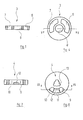
- the base disk 3 is drawn out in FIGS. 4 and 5. It comprises two annular segment-shaped water passage openings 6, 7 as well as a middle circular Passage opening 8, whose meaning clearly below becomes.
- control disk 4 is separate out drawn. It also includes two water passage openings 9, 10, in a circular segment-shaped Open recess 11, which of the base disk. 3 adjacent end side introduced into the control disk 4 is.
- the two water passages 9, 10 mutually separating web 12 has an angular extent, which is slightly larger than the angular extent the water passage opening 9, 10. The reason for this will be clear below.
- a central passage opening 13 of the control disk 4th is equipped with a non-circular cross section; she serves in a manner to be described the twisting the control disk 4 relative to the base disk.
- the stop disk 5 is the fifth the Umstellventils of Figures 1 and 2 separately drawn out.
- This stop disk 5 comprises a total of five Water passage openings 14, 15, 16, 17, 18, whose Size and shape of the water passage openings 9, 10th the control disk 4 corresponds. The between each two of these water passage openings 14, 15, 16, 17, 18 lying webs 19 correspond in their angular extent the web 12 of the control disk 4th
- the stop disk 5 has a central passage opening 20, with a non-round, in the present Case is provided with a pentagonal cross-section and the rotation of the stop disk 5 relative to the control disk 4 serves in a manner to be described.
- the base disk is 3 is applied to a step of the housing part 2a and by a suitable positive connection with the housing part 2a secured against rotation.
- the housing part 2a contains two water channels 21, 22, which point to the water passages 6, 7 of the base plate 3 are aligned, the have the same cross-sectional shape as this and parallel to Axle of the housing 2a, 2b to two side outlets 23, 24 lead, offset in the axial direction against each other are.
- the outlets 23, 24 communicate via an outer housing, which is not shown in the drawing and in which the described changeover device is used is, as well as over appropriate lines with the Head and side showers of a shower cubicle.
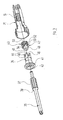
- the mechanism over which the control disk 4 opposite the stationary base plate 3 are rotated can, comprises a valve stem 25, which in the Figures 1 and 2 right housing part 2b coaxially interspersed, is guided in this rotatable and axially displaceable and on the outer head 26 an unrepresented Operating handle can be fixed in a known manner.
- the Valve spindle 25 expands on its inside End, approximately in the transition region between the two housing parts 2a, 2b, to an enlarged diameter apron 27, on its outer circumferential surface an external toothing 28 has.
- the external toothing 28 meshes with a Internal toothing 30 of a cup-shaped rotating insert 29, with its open side in Figures 1 and 2 right shows.
- the "bottom" of the cup-shaped rotating insert 29 is penetrated by a step bore 31 coaxial with the valve axis.
- the larger diameter portion of the stepped bore 31, which points to the left in Figures 1 and 2, carries an internal toothing 32, which cooperates with an external toothing 34 of a hollow shaft 33.
- the hollow shaft 33 extends coaxially to the valve axis through a bore of the housing part 2a, through the central passage opening 8 of the base disk 3 and ends in the central passage opening 13 of the control disk 4th Its local end is designed to be complementary to the shape of the passage opening 13, so that the latter can be rotated by turning the valve spindle 25 due to positive closures between the valve stem 25, the turning insert 29, the hollow shaft 33 and the control disk 4 relative to the base disk 3.
- the recess 11 of the control disk 4 can be brought into overlap with one of the two passage openings 6, 7 of the base disk 3.
- valve stem 25 can of accompanied by an axial movement, as the one inside the other gripping teeth 28 and 30 on the skirt 27 of the Valve stem 25 or on the rotary insert 29 in axial Direction can slide past each other without the rotation to lose.
- This axial degree of freedom of movement the valve stem 25 becomes, as will become clear later, needed to rotate the stop disk 5.
- a complementary spline 40 of a link part 39th postponed On the spline 37 of the stub shaft 35 is a complementary spline 40 of a link part 39th postponed.
- the gate part 39 is part of a gate mechanism, with the axial movement of the valve stem 25 in a rotational movement of the stub shaft 35 and thus the stop disk 5 can be implemented.
- the link member 39 can be compared to the stub shaft 35 axially be moved, with the rotary joint between the Sliding member 39 and the stub shaft 35 due to each other gripping splines 37, 39 is maintained.
- annular collar 41 On the outer circumference of the outer contour otherwise essentially cylindrical slide member 39 is a radially projecting annular collar 41 integrally formed. In mounted State extends, as Figure 1 shows, between the annular collar 41 of the gate part 39 and the "bottom" the turning insert 29, a first compression spring 42; a second, smaller diameter compression spring 43 is supported on the one hand at the bottom of the turning insert 29 and on the other on the annular shoulder 38 of the stub shaft 35 from.
- the link counter 47 is the second part of the above mentioned scenery mechanism. It has a cylindrical Area 48 on, in a corresponding hole the gate part 39 is guided, and a link structure 49, which has the same diameter as the tongues 44 of the gate part 39 and with the tongues 44 cooperates.
- the link structure 49 initially has on its outer circumferential surface ten axially parallel grooves 50, so twice as many grooves 50 as the slide member 39 tongues 44 has. These grooves 50 act in the assembled state with a corresponding number of ribs 51 on the inner circumferential surface the valve stem 25 together and prevent one Relative rotation between link counter 47 and Valve stem 25, but leave an axial relative movement these parts too.
- the in the direction of the gate part 39 facing end surfaces of the ribs 51 are below it Angle as the tongues 44 of the guide member 39 bevelled.
- the gate part 39 side facing five individual structures 52 which resemble a triangle, one side of which is parallel to the axis.
- the other Triangle side is slightly stepped in the middle, so that here a small, protruding "jagged" 53 arises.
- the link structure 49 of the backdrop opposite part 47 ten points, of which five points 53 in the figures 1 and 3 further right and five prongs 54 further left.
- the inclination of not parallel to Valve axis extending lateral boundary surfaces the slide structure 49 corresponds to the inclination of the bevelled End faces 45 of the tongues 44 of the gate part 39th
- the described changeover device is in the above mentioned outer housing installed so that in the Figures 1 and 2 left front side of the stopper disk 5 with the inflow of water communicates and their water passages 14 to 18 represent the inlet into the housing 2.
- valve spindle 25 moves inside the housing 2 inwards until they meet with the every other of the ribs 51 at the tongues 44 of the gate part 39 abuts; the intermediate ribs 51 protrude in each case a recess 46 between two tongues 44 of the Part of the gate into it. This movement becomes one Compression spring 61 compressed between the outer End face of the link counterpart 47 and the end face the bore of the valve stem 25 extends.
Landscapes
- Engineering & Computer Science (AREA)
- General Engineering & Computer Science (AREA)
- Mechanical Engineering (AREA)
- Multiple-Way Valves (AREA)
- Endoscopes (AREA)
- Bathtubs, Showers, And Their Attachments (AREA)
Applications Claiming Priority (2)
| Application Number | Priority Date | Filing Date | Title |
|---|---|---|---|
| DE10137611 | 2001-08-01 | ||
| DE10137611A DE10137611C1 (de) | 2001-08-01 | 2001-08-01 | Umstellvorrichtung für eine Sanitäreinrichtung mit mindestens zwei Wasserverbrauchern |
Publications (3)
| Publication Number | Publication Date |
|---|---|
| EP1281899A2 true EP1281899A2 (fr) | 2003-02-05 |
| EP1281899A3 EP1281899A3 (fr) | 2003-12-10 |
| EP1281899B1 EP1281899B1 (fr) | 2006-08-02 |
Family
ID=7693938
Family Applications (1)
| Application Number | Title | Priority Date | Filing Date |
|---|---|---|---|
| EP02014492A Expired - Lifetime EP1281899B1 (fr) | 2001-08-01 | 2002-06-29 | Dispositif de changement de régime pour dispositif sanitaire avec au moins deux utilisateurs |
Country Status (3)
| Country | Link |
|---|---|
| EP (1) | EP1281899B1 (fr) |
| AT (1) | ATE335150T1 (fr) |
| DE (2) | DE10137611C1 (fr) |
Cited By (7)
| Publication number | Priority date | Publication date | Assignee | Title |
|---|---|---|---|---|
| CN106763904A (zh) * | 2016-12-22 | 2017-05-31 | 厦门建霖工业有限公司 | 带暂停水三向分流器 |
| CN107178125A (zh) * | 2017-07-14 | 2017-09-19 | 侯文博 | 一体双路调节淋浴装置 |
| EP3457010A1 (fr) * | 2017-09-15 | 2019-03-20 | Hansgrohe SE | Dériveur de fluide |
| WO2021204518A1 (fr) * | 2020-04-09 | 2021-10-14 | Neoperl Gmbh | Dispositif inverseur, série de dispositifs inverseurs et utilisation d'une interface commune pour fixer différentes variantes de dispositifs inverseurs |
| EP3945230A1 (fr) * | 2020-07-31 | 2022-02-02 | Xiamen Solex High-Tech Industries Co., Ltd. | Soupape de commande multifonction et douche comprenant ladite soupape |
| CN114017517A (zh) * | 2021-09-28 | 2022-02-08 | 福建西河卫浴科技有限公司 | 一种阀芯、龙头和厨卫器具 |
| CN114017518A (zh) * | 2021-09-28 | 2022-02-08 | 福建西河卫浴科技有限公司 | 一种阀芯、龙头和厨卫器具 |
Families Citing this family (8)
| Publication number | Priority date | Publication date | Assignee | Title |
|---|---|---|---|---|
| DE102007026828A1 (de) | 2007-06-06 | 2008-12-11 | Grohe Ag | Absperr- und/oder Umschaltventil |
| DE102009008194B4 (de) * | 2009-02-02 | 2011-07-28 | Hansgrohe AG, 77761 | Sanitäres Abschalt- beziehungsweise Umschaltventil |
| DE102011003050B4 (de) * | 2011-01-24 | 2014-11-27 | Hansgrohe Se | Sanitäres Abschalt- bzw. Umschaltventil |
| DE102015216180A1 (de) * | 2015-08-25 | 2017-03-02 | Hansgrohe Se | Sanitäre Umschalteinrichtung und Sanitärarmatur |
| CN206567112U (zh) * | 2017-01-06 | 2017-10-20 | 厦门建霖工业有限公司 | 一种具有双按键的过水结构 |
| DE102019202273A1 (de) * | 2019-02-20 | 2020-08-20 | Hansgrohe Se | Umstellventilvorrichtung |
| HUP1900114A1 (hu) | 2019-04-05 | 2020-10-28 | Kerox Ipari Es Kereskedelmi Kft | Vezérelt dugattyús szelep |
| HUP1900162A1 (hu) | 2019-05-16 | 2020-11-30 | Kerox Ipari Es Kereskedelmi Kft | Nyomógombos szeleppel vezérelt kartus víz keverésére és/vagy víznek egy vagy több beömlés egy vagy több kiömléshez történõ továbbítására |
Family Cites Families (8)
| Publication number | Priority date | Publication date | Assignee | Title |
|---|---|---|---|---|
| NL6514563A (fr) * | 1965-11-10 | 1967-05-11 | ||
| US4286623A (en) * | 1978-11-10 | 1981-09-01 | Moschoula Spanides | Faucet control device |
| DE4035838A1 (de) * | 1990-11-10 | 1992-07-23 | Grohe Armaturen Friedrich | Wasserventil fuer sanitaere anlagen |
| US5546983A (en) * | 1994-11-03 | 1996-08-20 | Friedrich Grohe Aktiengesellschaft | Shut-off valve |
| US5741005A (en) * | 1996-03-15 | 1998-04-21 | Fleck Controls, Inc. | Rotary disk control valve for a water conditioning system |
| DE19614653A1 (de) * | 1996-04-13 | 1997-10-16 | Grohe Armaturen Friedrich | Ventil |
| CN1182452C (zh) * | 1999-05-07 | 2004-12-29 | 马斯科公司 | 恒温混合阀 |
| US6799604B1 (en) * | 2000-01-19 | 2004-10-05 | Newteam Limited | Selector valve arrangement |
-
2001
- 2001-08-01 DE DE10137611A patent/DE10137611C1/de not_active Expired - Fee Related
-
2002
- 2002-06-29 DE DE50207692T patent/DE50207692D1/de not_active Expired - Lifetime
- 2002-06-29 AT AT02014492T patent/ATE335150T1/de active
- 2002-06-29 EP EP02014492A patent/EP1281899B1/fr not_active Expired - Lifetime
Non-Patent Citations (1)
| Title |
|---|
| None |
Cited By (11)
| Publication number | Priority date | Publication date | Assignee | Title |
|---|---|---|---|---|
| CN106763904A (zh) * | 2016-12-22 | 2017-05-31 | 厦门建霖工业有限公司 | 带暂停水三向分流器 |
| CN106763904B (zh) * | 2016-12-22 | 2023-08-08 | 厦门建霖健康家居股份有限公司 | 带暂停水三向分流器 |
| CN107178125A (zh) * | 2017-07-14 | 2017-09-19 | 侯文博 | 一体双路调节淋浴装置 |
| CN107178125B (zh) * | 2017-07-14 | 2023-01-24 | 侯文博 | 一体双路调节淋浴装置 |
| EP3457010A1 (fr) * | 2017-09-15 | 2019-03-20 | Hansgrohe SE | Dériveur de fluide |
| CN109506007A (zh) * | 2017-09-15 | 2019-03-22 | 汉斯格罗欧洲公司 | 流体切换装置 |
| US10794500B2 (en) | 2017-09-15 | 2020-10-06 | Hansgrohe Se | Fluid switch-over device |
| WO2021204518A1 (fr) * | 2020-04-09 | 2021-10-14 | Neoperl Gmbh | Dispositif inverseur, série de dispositifs inverseurs et utilisation d'une interface commune pour fixer différentes variantes de dispositifs inverseurs |
| EP3945230A1 (fr) * | 2020-07-31 | 2022-02-02 | Xiamen Solex High-Tech Industries Co., Ltd. | Soupape de commande multifonction et douche comprenant ladite soupape |
| CN114017517A (zh) * | 2021-09-28 | 2022-02-08 | 福建西河卫浴科技有限公司 | 一种阀芯、龙头和厨卫器具 |
| CN114017518A (zh) * | 2021-09-28 | 2022-02-08 | 福建西河卫浴科技有限公司 | 一种阀芯、龙头和厨卫器具 |
Also Published As
| Publication number | Publication date |
|---|---|
| ATE335150T1 (de) | 2006-08-15 |
| DE10137611C1 (de) | 2003-04-30 |
| EP1281899A3 (fr) | 2003-12-10 |
| DE50207692D1 (de) | 2006-09-14 |
| EP1281899B1 (fr) | 2006-08-02 |
Similar Documents
| Publication | Publication Date | Title |
|---|---|---|
| EP1281899B1 (fr) | Dispositif de changement de régime pour dispositif sanitaire avec au moins deux utilisateurs | |
| EP0732147B1 (fr) | Pomme de douche multifonction | |
| EP2796205B1 (fr) | Pomme de douche à mouvement rotatif pouvant être bloqué par une came de commande | |
| DE102009008194B4 (de) | Sanitäres Abschalt- beziehungsweise Umschaltventil | |
| EP0242675B1 (fr) | Vanne mélangeuse | |
| DE4415785C2 (de) | Brausekopf mit Umsteller | |
| DE3790206C2 (de) | Einhebelmischventil | |
| EP2988876B1 (fr) | Pomme de douche à disque de commande rotatif | |
| EP3457010B1 (fr) | Dériveur de fluide | |
| DE102018206354B3 (de) | Misch- und Absperrventilvorrichtung sowie sanitäre Misch- und Absperrarmatur | |
| EP0485841A1 (fr) | Robinet sanitaire | |
| EP1736695A1 (fr) | Vanne, notamment pour une robinetterie sanitaire | |
| DE60022787T2 (de) | Mehrwegventil | |
| EP1061300B1 (fr) | Actionneur | |
| DE4330535C1 (de) | Sanitäres Einhebel-Mischventil | |
| DE102011003050B4 (de) | Sanitäres Abschalt- bzw. Umschaltventil | |
| EP1022634A1 (fr) | Cartouche pour robinetterie sanitaire | |
| DE102016211645B3 (de) | Brauseumstellventil und Sanitärbrause | |
| CH671078A5 (fr) | ||
| EP1319144A1 (fr) | Cartouche pour robinetterie sanitaire | |
| EP2251578B1 (fr) | Poignée rotative pour une armature sanitaire | |
| DE202018104944U1 (de) | Brauseumstellventil und Sanitärbrause | |
| DE60215545T2 (de) | Brauseschlauch mit einem zweiwegeventil und zweiwegenventil für brauseschlauch | |
| DE3441468C2 (fr) | ||
| EP0855545A2 (fr) | Poignée pour robinet sanitaire |
Legal Events
| Date | Code | Title | Description |
|---|---|---|---|
| PUAI | Public reference made under article 153(3) epc to a published international application that has entered the european phase |
Free format text: ORIGINAL CODE: 0009012 |
|
| AK | Designated contracting states |
Designated state(s): AT BE CH CY DE DK ES FI FR GB GR IE IT LI LU MC NL PT SE TR |
|
| AX | Request for extension of the european patent |
Extension state: AL LT LV MK RO SI |
|
| PUAL | Search report despatched |
Free format text: ORIGINAL CODE: 0009013 |
|
| AK | Designated contracting states |
Kind code of ref document: A3 Designated state(s): AT BE CH CY DE DK ES FI FR GB GR IE IT LI LU MC NL PT SE TR |
|
| AX | Request for extension of the european patent |
Extension state: AL LT LV MK RO SI |
|
| 17P | Request for examination filed |
Effective date: 20040416 |
|
| 17Q | First examination report despatched |
Effective date: 20040513 |
|
| AKX | Designation fees paid |
Designated state(s): AT CH DE FR LI NL |
|
| GRAP | Despatch of communication of intention to grant a patent |
Free format text: ORIGINAL CODE: EPIDOSNIGR1 |
|
| GRAC | Information related to communication of intention to grant a patent modified |
Free format text: ORIGINAL CODE: EPIDOSCIGR1 |
|
| GRAS | Grant fee paid |
Free format text: ORIGINAL CODE: EPIDOSNIGR3 |
|
| GRAA | (expected) grant |
Free format text: ORIGINAL CODE: 0009210 |
|
| AK | Designated contracting states |
Kind code of ref document: B1 Designated state(s): AT CH DE FR LI NL |
|
| PG25 | Lapsed in a contracting state [announced via postgrant information from national office to epo] |
Ref country code: NL Free format text: LAPSE BECAUSE OF FAILURE TO SUBMIT A TRANSLATION OF THE DESCRIPTION OR TO PAY THE FEE WITHIN THE PRESCRIBED TIME-LIMIT Effective date: 20060802 |
|
| REG | Reference to a national code |
Ref country code: CH Ref legal event code: EP |
|
| REF | Corresponds to: |
Ref document number: 50207692 Country of ref document: DE Date of ref document: 20060914 Kind code of ref document: P |
|
| REG | Reference to a national code |
Ref country code: CH Ref legal event code: NV Representative=s name: FREI PATENTANWALTSBUERO |
|
| NLV1 | Nl: lapsed or annulled due to failure to fulfill the requirements of art. 29p and 29m of the patents act | ||
| ET | Fr: translation filed | ||
| PLBE | No opposition filed within time limit |
Free format text: ORIGINAL CODE: 0009261 |
|
| STAA | Information on the status of an ep patent application or granted ep patent |
Free format text: STATUS: NO OPPOSITION FILED WITHIN TIME LIMIT |
|
| 26N | No opposition filed |
Effective date: 20070503 |
|
| REG | Reference to a national code |
Ref country code: FR Ref legal event code: PLFP Year of fee payment: 15 |
|
| PGFP | Annual fee paid to national office [announced via postgrant information from national office to epo] |
Ref country code: CH Payment date: 20160620 Year of fee payment: 15 |
|
| REG | Reference to a national code |
Ref country code: FR Ref legal event code: PLFP Year of fee payment: 16 |
|
| REG | Reference to a national code |
Ref country code: CH Ref legal event code: PL |
|
| PG25 | Lapsed in a contracting state [announced via postgrant information from national office to epo] |
Ref country code: CH Free format text: LAPSE BECAUSE OF NON-PAYMENT OF DUE FEES Effective date: 20170630 Ref country code: LI Free format text: LAPSE BECAUSE OF NON-PAYMENT OF DUE FEES Effective date: 20170630 |
|
| REG | Reference to a national code |
Ref country code: FR Ref legal event code: PLFP Year of fee payment: 17 |
|
| PGFP | Annual fee paid to national office [announced via postgrant information from national office to epo] |
Ref country code: FR Payment date: 20190628 Year of fee payment: 18 |
|
| PGFP | Annual fee paid to national office [announced via postgrant information from national office to epo] |
Ref country code: AT Payment date: 20190701 Year of fee payment: 18 Ref country code: DE Payment date: 20190628 Year of fee payment: 18 |
|
| REG | Reference to a national code |
Ref country code: DE Ref legal event code: R119 Ref document number: 50207692 Country of ref document: DE |
|
| REG | Reference to a national code |
Ref country code: AT Ref legal event code: MM01 Ref document number: 335150 Country of ref document: AT Kind code of ref document: T Effective date: 20200629 |
|
| PG25 | Lapsed in a contracting state [announced via postgrant information from national office to epo] |
Ref country code: FR Free format text: LAPSE BECAUSE OF NON-PAYMENT OF DUE FEES Effective date: 20200630 |
|
| PG25 | Lapsed in a contracting state [announced via postgrant information from national office to epo] |
Ref country code: DE Free format text: LAPSE BECAUSE OF NON-PAYMENT OF DUE FEES Effective date: 20210101 Ref country code: AT Free format text: LAPSE BECAUSE OF NON-PAYMENT OF DUE FEES Effective date: 20200629 |