EP1281344A2 - Mop cover and wiping system with mop cover and stretching frame - Google Patents
Mop cover and wiping system with mop cover and stretching frame Download PDFInfo
- Publication number
- EP1281344A2 EP1281344A2 EP02405664A EP02405664A EP1281344A2 EP 1281344 A2 EP1281344 A2 EP 1281344A2 EP 02405664 A EP02405664 A EP 02405664A EP 02405664 A EP02405664 A EP 02405664A EP 1281344 A2 EP1281344 A2 EP 1281344A2
- Authority
- EP
- European Patent Office
- Prior art keywords
- mop cover
- band
- frame
- mop
- tenter
- Prior art date
- Legal status (The legal status is an assumption and is not a legal conclusion. Google has not performed a legal analysis and makes no representation as to the accuracy of the status listed.)
- Withdrawn
Links
Images


Classifications
-
- A—HUMAN NECESSITIES
- A47—FURNITURE; DOMESTIC ARTICLES OR APPLIANCES; COFFEE MILLS; SPICE MILLS; SUCTION CLEANERS IN GENERAL
- A47L—DOMESTIC WASHING OR CLEANING; SUCTION CLEANERS IN GENERAL
- A47L13/00—Implements for cleaning floors, carpets, furniture, walls, or wall coverings
- A47L13/10—Scrubbing; Scouring; Cleaning; Polishing
- A47L13/20—Mops
- A47L13/24—Frames for mops; Mop heads
- A47L13/254—Plate frames
- A47L13/258—Plate frames of adjustable or foldable type
-
- A—HUMAN NECESSITIES
- A47—FURNITURE; DOMESTIC ARTICLES OR APPLIANCES; COFFEE MILLS; SPICE MILLS; SUCTION CLEANERS IN GENERAL
- A47L—DOMESTIC WASHING OR CLEANING; SUCTION CLEANERS IN GENERAL
- A47L13/00—Implements for cleaning floors, carpets, furniture, walls, or wall coverings
- A47L13/10—Scrubbing; Scouring; Cleaning; Polishing
- A47L13/20—Mops
Definitions
- the invention relates to a mop cover according to the preamble of claim 1 and a Wiping system according to the preamble of claim 14.
- Mop covers for use with a stenter have been known for a long time.
- Such Mop covers have a holder on the back, in which a clamping frame can intervene.
- the mop cover is stretched onto the tenter frame.
- the holder is usually formed by two mutually oriented and in Pockets spaced apart.
- the tenter in turn usually exists from two pivotally connected frame parts or wings, the Ends can be inserted into the pockets.
- the two inserted into the pockets Frame parts can be spread apart and fixed in the flat position become.
- the mop cover stretched on the clamping frame can be used to damp or dry floor cleaning can be used.
- Mop covers with which the floor is cleaned with a damp cloth, have to be changed from time to time are moistened and freed of adhering dirt. For this, the mop cover is in swirled and wrung out in a wash bucket filled with water. Known Mop covers must be removed from the stenter to wring them out. This is cumbersome and time consuming.
- DE-A-40 22 36 discloses a mop cover with two opposite one another Bags into which the ends of a collapsible mop holder can be inserted.
- a tab is attached to the inside of the bag on only one side.
- At the top of the Two straps are formed with ring-shaped eyelets. The straps with the eyelets can be attached to the end thickening of the transverse axis of the mop holder become. If the mop holder spanning the mop cover is folded up, so the mop cover still hangs on one narrow side of the mop holder and can be used raised, rinsed in a bucket and wrung out in a vertical press become.
- EP-A-0 111 820 shows a mop cover which has detachable fastening means having.
- the fasteners are formed by a tab with push buttons, which can be placed around a strap of the mop holder.
- the Fasteners allow the mop cover to hang freely from a press or a Keep container with cleaning liquid.
- a disadvantage of the known mop covers is that they are when folded Hang the mop holder swinging freely on one narrow side. Free swinging mop covers cannot be easily inserted into a bucket or press. Another disadvantage is that the mop holder - due to the length of the stretched mop cover - is wide must be raised so that the mop cover does not touch the floor.
- the object of the present invention is to provide a mop cover which can easily be wrung out.
- the mop cover should also be designed that he no longer has to be held in his hands to wring it out.
- Another one The aim is to provide a wiping system consisting of a wiping cover and stenter frame enables a quick installation of the mop cover on the stenter frame.
- Another goal is to provide a tenter or mop cover holder with which a Mop cover quickly and conveniently.
- connection and Spacer for releasable and spaced connection of the mop cover at least two places with the pivotable clamping frame parts one Tenter frames are provided.
- the connection and spacing means are preferably in the area of the bags provided on the narrow sides of the mop cover or fixable.
- This new type of mop cover has the advantage that it can also be opened of the tenter via the connecting and spacing means on at least two in Places spaced from each other remains connected to the tenter.
- This has the advantage that the mop cover is folded at the same time when it is lifted.
- the raised mop cover hangs folded up on the tenter frame and can be used e.g.
- connection and Distance means at least one band, a cord or the like.
- the tape resp. the Cord means, e.g. have a hook, carabiner or the like, so the mop cover can be coupled to the tenter frame parts.
- this is at least one band or the at least one cord, in particular symmetrically with respect to a central plane, arranged on the back that the mop cover when lifting with the stenter approximately in the middle collapses. This allows effective wringing out in a suitable press.
- connection and spacing means are advantageously designed in this way and with the Tenter connectable that the tenter at least partially can be folded without the mop cover being folded. So there is preferably only a loose connection via flexible connection and spacing means between the mop cover and the stenter. Conveniently they have Connection and distance means such a length that the raised mop cover too the folded stenter ends is spaced. This is important otherwise there is a risk that the clamping frame parts when pressing the Mop covers are also recorded by the press.
- the tape or cord is advantageously detachable on the back of the mop cover arranged.
- This can be achieved, for example, in that the one end of the Bands fixed, e.g. is secured by a seam and the other second end is detachable, e.g. can be fastened by means of a Velcro fastener or other known connecting means is.
- the band preferably consists of two band sections, the first ends of the Band sections on the back of the mop cover, especially at a distance from the short side edges, are fixed and a detachable closure, e.g. Velcro fastener, for connecting the second ends of the two band sections is provided.
- a detachable closure e.g. Velcro fastener
- the length of the band respectively. the two band sections longer than the distance between the joints of the first tape ends with the back of the flat mop cover. Accordingly, it can Band resp. the interconnected band sections form a loose loop.
- the Connection and spacing means have at least such a length that the to Wring out raised mop cover is spaced from the open stenter.
- the raised mop cover is preferably more than 1 cm and preferably more than 5 Centimeters from the stenter ends. But it can also be more than 10 cm, for example, be suspended 30 cm from the stenter.
- Additional detachable fastening means can expediently be provided for Attachment of the tape respectively. the tape sections on the back of the mop cover. This has the advantage that the band can be fixed to the mop cover if it is not should be used.
- the first ends of the band are advantageously fixed in the area of the pockets on the back.
- the strap ends can also be used to attach the pockets be sewn to the back.
- the additional tape parts can be attached without significant additional manufacturing effort. Expediently are at a distance from the longitudinal edges on the back of the Mop cover longitudinal beads are provided, which act as guides for the stenter can serve. If the wrung-out mop cover is placed on the floor, you need just make sure that the free ends of the clamping frame parts inside the longitudinal beads come to rest. When unfolded, the remains Tensioning frame guided through the longitudinal beads between the longitudinal beads. That’s it Inserting the tenter into the pockets covering the longitudinal beads is essential facilitated.
- the present invention also relates to a wiping system with a wiping cover according to one of claims 1 to 14 and a stenter with at least two mutually pivotally connected clamping frame parts for clamping the Mop cover and a swivel mount provided on the stenter for attaching a stem.
- the distal ends of the clamping frame parts in the collapsed are advantageous State symmetrically arranged with respect to an imaginary central plane.
- This has the Advantage that the ends of the clamping frame parts open when the clamping frame is raised are at the same height (horizontal), and the mop cover is even on Stenter hangs.
- both short longitudinal edges of the Tension frame parts on the mop cover evenly when the tension frame is open the mop cover is removed.
- the pivot axis of the interconnected tenter frame parts runs approximately in the middle. This has the advantage that the mop cover when lifting by means of the The stretcher folds the hinges in the middle, causing a wringing out a press relieved.
- the stenter has one formed from a strong wire Frame. This is an inexpensive construction. However, it is also conceivable to have one To manufacture stenter from plastic. to use. It is preferable to the opposite ends of the tenter provided a guide for the tape. This has the advantage that the tape is not loose and is annoying when cleaning.
- the guide is expediently a slot which is separated by a strut arranged on the narrow side of the frame.
- the tape is particularly preferred passed through the slot from below. This has the advantage that when the Mop the narrow edges of the tenter frame on the belt and this when unfolding the tensioning frame parts to form a loop stretch. It is conceivable to provide several slots through which the tape loops can be. If two slots are used, the band sections can be under the stenter are connected to each other.
- the tape advantageously consists of two tape sections of approximately the same length and the Closure is a Velcro.
- the Velcro fastener is on each other adjacent second band ends provided. Because the Velcro fastener is stiffened Point of the belt, it does not slide over the bracket when lifting the mop cover of the stenter and remains in the middle. This always causes the mop cover collapses in the middle and evenly on the collapsed stenter is hung.
- the narrow Tenter frame rolling means may be provided.
- the rolling stock has the purpose of Folding apart and inserting the tenter into the pockets easier.
- the frame can be narrow A tubular sleeve must be placed on the clamping frame side. Thanks to the rotatable tube sleeve you can the stenter parts on the belt resp. Roll off the mop cover. It is conceivable especially with plastic versions of the stenter, instead of a tubular sleeve to provide one or more roles. The roles can be by means of Dovetail connections can be plugged together.
- Longitudinal beads are provided, which serve as positive guides for the stenter can.
- the positive guides allow the stenter to be in the pockets to introduce without having to bend down.
- the present invention also relates to a tenter frame for a mop cover with two clamping frame parts which can be pivoted relative to one another and which extend from one unfolded, extended position, in which a mop cover through the ends the clamping frame parts are clamped in a folded position are pivotable, characterized in that at the ends of the clamping frame parts Roll means are provided.
- the rolling means have the advantage that the clamping frame parts only with little rolling resistance in the opposite pockets of one Mop covers are insertable. In contrast, it works with the known Tensioning frame between the ends of the tensioning frame parts and the Mop cover surface a friction resistance, which the insertion of the Tension frame ends in the pockets of the mop cover much more difficult. Further Advantages of the tenter frame according to the invention are in the dependent Device claims defined.
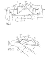
- Figures 1 to 3 show a mop cover 11 according to the invention, which for Use on a clamping frame 13 can be clamped ( Figures 4 to 6).
- the mop cover 11 has a cleaning side 15 facing the surface to be cleaned and one of the The cleaning side 15 is facing away from the rear side 17 pockets 19 arranged from one another are provided, which accommodate the reception of the Serve frame 13.
- the mop cover 11 With the help of a arranged on the back 17, from the In both belt sections 21a and 21b of existing belt 21, the mop cover 11 is detachable can be connected or coupled to the tenter frame 13.
- the mop cover 11 thus remains with the Tenter connected, and can be lifted with this ( Figure 6). This enables the mop cover to be inserted into a press and wrung out without it would have to be taken into your hands.
- the mop cover 11 is made of a cleaning textile, not shown in detail, which has a trim of cleaning fibers or threads 23 on one side.
- the Cleaning threads 23 preferably consist of a large number of microfibers Thickness of at most 30 dtex, preferably less than 20 dtex and particularly preferred less than 10 dtex. Microfibers have the advantage of being contaminated with them Surfaces cleaned mechanically and without the use of chemical agents can be.
- the mop cover 11 has an edge 25 on the back 17, which also has Cleaning fibers 23 is occupied.
- 25a is the edge of the broadside
- 25b the Inscribed on the edge of the narrow side of the mop cover.
- the edges 25a, 25b can by single or double folding of the one-sided with cleaning fibers Cleaning textile and sewing it with the back.
- a longitudinal bead 27 is formed on the edge 25a of the broad side. This Longitudinal bead 27 can be produced by appropriately sewing the folded over Cleaning textile and edging the formed bead with a textile strip.
- the pockets 19 adjoin the edges 25a, 25b of the narrow sides. You are educated by a preferably reinforced plastic band, which is over the other opposite longitudinal beads 27 and below the folded edges 25a, 25b extends. Seams 29a, 29b, not shown, which run parallel to the edges connect the folded edges 25a, 25b and the pockets 19 to the back 17 of the Mop cover 11.
- the belt 21 consists of the belt sections 21a and 21b, which have a first end are fixed on the back 17 of the mop cover.
- the Band sections 21a, 21b between the longitudinal beads 27 and in the pockets 19. They are preferably attached to the bottom of the bag.
- the first ends of the band sections 21a, 21b can also with the seams 29b with the back 17 of the mop cover be connected.
- Detachable fastening means 33 are provided, with which the band sections 21a, 21b can be detached are interconnectable.
- the closure means 33 are preferably a textile Surface fastener, e.g. a Velcro with hooks that work together 33a and stitches 33b.
- a second Velcro fastener 33c may be provided on the belt section 21b. Act the cooperating adhesive portions 33a and 33c together, so the Band sections close to the back 17. It is conceivable that the top of the Band section 21b has meshes of a Velcro fastener over the entire surface, so that section 33a can be ascertained at any point on band section 21b. Are the Band sections 21a, 21b placed around the tenter frame 13, so the mop cover 11 remains with the tenter frame 13 connected to the latter.
- the two Belt sections can be connected to each other or independently of each other band section on the stenter, e.g. on a strut provided on the bracket, be fixable.
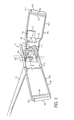
- the tenter frame 11 has two hinged wings or Frame parts 35a and 35b.
- a frame part 35a On a frame part 35a is a receptacle 37 for a handle 39 provided.
- the receptacle 37 is in the middle section of an S-shaped, in Longitudinal direction of the tenter frame 11 extending axis 41 pivotable arranged.
- the pivot axis 43 running through the central section thus runs essentially transverse to the longitudinal extension of the tenter 11.
- the axis 41 in turn is free from the frame part 35a upwardly projecting webs 45 about an axis of rotation 48 rotatably mounted. Due to this construction, the stem 39 is free on all sides flexible, which allows the greatest freedom in floor cleaning.
- the webs 45 are formed on a base plate 47, on which a first U-shaped one Bracket 49a of the first frame part 35a is fixed. Another U-shaped Bracket 49b is on the underside of the base plate 47 in the middle of the flat stenter hinged.
- a mounting plate 52 arranged on the bracket 49b one is upward protruding metal spring 51 arranged so that the terminal edge 53 of the base plate 47b can snap into a bulge in the spring 51.
- the metal spring 51 has one flat pawl 55, which can be operated with one foot. The pawl 55 is down pressed, the two frame parts can be pivoted and out of the pockets 19 withdrawn ( Figures 4 and 6).
- Struts 59 are spaced apart from the base sections 57a, 57b of the brackets 49a, 49b intended.
- the struts 59 together with the base portions 57a, 57b define one Passage or slot 61 through which the belt sections 21a and 21b are guided can be.
- the band 31, respectively. are the band sections 21a, 21b longer than the distance between those at the rear of the flat mop cover set first ends. To open the mop cover 11 the band sections 21a, 21b from below or from above through the slits 61 guided and the ends of which are releasably connected to the Velcro fastener (FIG. 4).
- bracket 49a, 49b these are first on the back 17 between the Longitudinal beads 27 supported and then spread apart. If the tape sections 49a, 49b are guided through the slots from below, the base sections 57a, 57b rest volume 21. When the frame parts 35a, 35b are spread apart, the band 21 folded and stretched in the area of the pockets. The band 21 is therefore not loose, but substantially stretched when the tenter 13 is inserted into the pockets 19.
- a tubular sleeve 63 is provided.
- the tubular sleeve 63 is freely rotatable so that the brackets 49a, 49b for insertion into the pockets 29 on the belt 21 can roll.
- rollers can also be provided. these can for example made of plastic and clipped together.
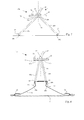
- the second exemplary embodiment of a clamping frame 11a according to FIGS. 7 to 10 has a holding plate 65, on which two clamping frame parts 66a, 66b are articulated.
- the tenter frame parts 66a, 66b are spaced apart by two Swivel axes 67a, 67b pivotable.
- On the holding plate 65 is a receptacle 37 for a stem not shown in the figures.
- the receptacle 37 is by means of a universal joint 69 connected to the holding plate 65.
- Detachable locking means serve the clamping frame parts 66a, 66b in the stretched state with the holding plate 65 to connect.
- the locking means can, for example, by means of a Spring biased latch 72 or locking bolt formed on the Holding plate 65 received in guides, not shown, and relative to Holding plate 65 is slidable.
- tenter frame parts 66a, 66b provided after Protrusions 73 projecting from above with undercuts 75 act with the latch 72 stretched frame parts 66a, 66b together and place the frame parts 66a, 66b to the holding plate 65.
- a movable actuator 71 acts with the bolt 72 together and pushes it against actuation against a spring preload a locking position in a release position.
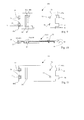
- the rolling means 77 are preferably two at a distance from one another arranged rollers, which in a recess 79 in the clamping frame parts 66a, 66b are rotatably arranged.
- the rollers 77 are not in the recesses 79 by means of a Axles shown in more detail rotatably mounted.
- ears 81 are formed at the proximal end of the stenter parts 66a, 66b.
- the ears 81 have a round hole 83 for receiving a further axis for the articulated connection of the clamping frame parts 66a, 66b with the Holding plate 65.
- Recess 84 is provided, which through a roller 87 in two slots 85a and 85b is divided. Through the slots 85a, 85b, the band 21 can be used to connect the Mop cover 11 are looped to the tenter frame 11a. As from FIGS. 7 and 8 can be seen, the clamping frame 11a is symmetrical with respect to a central plane 86. As a result, the mop cover, when the stenter is released and if this is raised, automatically folded in the middle.
- the exemplary embodiment according to FIG. 11 differs from the example according to FIGS 9 and 10 in that no roller 87 is provided in the recess 84. Accordingly, the band sections 21a, 21b from above, respectively. outside through the Recesses 84 guided and releasably connected to each other (see. Fig. 8).
- a mop cover for a collapsible stenter 13 has one Cleaning fibers, threads or the like having cleaning side 15 and one of the Cleaning side 15 facing away from the back 17 with two spaced apart arranged and mutually oriented pockets 19.
- the pockets 19 serve the Inclusion of a clamping frame 13.
- Connecting and spacing means 21 preferably a flexible band or cord, for detachable and spaced connection of the mop cover to the tensioning frame 13 intended.
Abstract
Description
Die Erfindung betrifft ein Wischbezug gemäss Oberbegriff von Anspruch 1 sowie ein Wischsystem gemäss Oberbegriff von Anspruch 14.The invention relates to a mop cover according to the preamble of claim 1 and a Wiping system according to the preamble of claim 14.
Wischbezüge zum Gebrauch mit einem Spannrahmen sind seit langem bekannt. Derartige Wischbezüge weisen auf der Rückseite eine Halterung auf, in welche ein Spannrahmen eingreifen kann. Zum Putzen wird der Wischbezug auf den Spannrahmen aufgespannt. Üblicherweise ist die Halterung gebildet durch zwei gegeneinander orientierte und in Abstand voneinander angeordnete Taschen. Der Spannrahmen seinerseits besteht meist aus zwei verschwenkbar miteinander verbundenen Rahmenteilen oder Flügeln, deren Enden in die Taschen eingeführt werden können. Die beiden in die Taschen eingeführten Rahmenteile können auseinandergespreizt und in der flachen Position festgestellt werden. Der auf den Spannrahmen aufgespannte Wischbezug kann zur feuchten oder trockenen Bodenreinigung verwendet werden.Mop covers for use with a stenter have been known for a long time. such Mop covers have a holder on the back, in which a clamping frame can intervene. For cleaning, the mop cover is stretched onto the tenter frame. The holder is usually formed by two mutually oriented and in Pockets spaced apart. The tenter in turn usually exists from two pivotally connected frame parts or wings, the Ends can be inserted into the pockets. The two inserted into the pockets Frame parts can be spread apart and fixed in the flat position become. The mop cover stretched on the clamping frame can be used to damp or dry floor cleaning can be used.
Wischbezüge, mit welchen der Boden feucht gereinigt wird, müssen von Zeit zu Zeit neu befeuchtet und vom anhaftenden Schmutz befreit werden. Dazu wird der Wischbezug in einem mit Wasser gefüllten Wascheimer geschwenkt und ausgewrungen. Bekannte Wischbezüge müssen zum Auswringen vom Spannrahmen genommen werden. Dies ist umständlich und zeitraubend.Mop covers, with which the floor is cleaned with a damp cloth, have to be changed from time to time are moistened and freed of adhering dirt. For this, the mop cover is in swirled and wrung out in a wash bucket filled with water. Known Mop covers must be removed from the stenter to wring them out. This is cumbersome and time consuming.
Die DE-A-40 22 36 offenbart einen Wischbezug mit zwei einander gegenüberliegenden Taschen, in welche die Enden eines zusammenklappbaren Mophalters einführbar sind. Auf lediglich einer Seite ist innerhalb der Tasche eine Lasche befestigt. An der Spitze der Lasche sind zwei Bänder mit ringförmigen Ösen angeformt. Die Bänder mit den Ösen können an den endseitigen Verdickungen der Querachse des Mophalters festgelegt werden. Wird der den Wischbezug aufspannende Mophalter zusammengeklappt, so hängt der Wischbezug weiterhin an der einen Schmalseite am Mophalter und kann mit diesem angehoben, in einem Eimer gespült und in einer Vertikalpresse ausgewrungen werden. DE-A-40 22 36 discloses a mop cover with two opposite one another Bags into which the ends of a collapsible mop holder can be inserted. A tab is attached to the inside of the bag on only one side. At the top of the Two straps are formed with ring-shaped eyelets. The straps with the eyelets can be attached to the end thickening of the transverse axis of the mop holder become. If the mop holder spanning the mop cover is folded up, so the mop cover still hangs on one narrow side of the mop holder and can be used raised, rinsed in a bucket and wrung out in a vertical press become.
Die EP-A-0 111 820 zeigt einen Mopbezug, welcher einseitig lösbare Befestigungsmittel aufweist. Die Befestigungsmittel sind gebildet duch eine Lasche mit Druckknöpfen, welche um einen Bügelsteg des Mophalters herumgelegt werden kann. Die Befestigungsmittel erlauben, den Mopbezug frei hängend zu einer Presse oder einem Behältnis mit Reinigungsflüssigkeit zu führen.EP-A-0 111 820 shows a mop cover which has detachable fastening means having. The fasteners are formed by a tab with push buttons, which can be placed around a strap of the mop holder. The Fasteners allow the mop cover to hang freely from a press or a Keep container with cleaning liquid.
Nachteilig an den bekannten Mopbezügen ist, dass diese bei zusammengeklapptem Mophalter frei pendelnd an der einen Schmalseite hängen. Frei pendelnde Mopbezüge lassen sich jedoch nicht leicht in einen Eimer oder Presse einführen. Weiter ist nachteilig, dass der Mophalter - bedingt durch die Länge des gestreckten Mopbezugs - weit angehoben werden muss, damit der Mopbezug nicht am Boden streift.A disadvantage of the known mop covers is that they are when folded Hang the mop holder swinging freely on one narrow side. Free swinging mop covers cannot be easily inserted into a bucket or press. Another disadvantage is that the mop holder - due to the length of the stretched mop cover - is wide must be raised so that the mop cover does not touch the floor.
Aufgabe der vorliegenden Erfindung ist es, einen Wischbezug bereitzustellen, welcher einfach ausgewrungen werden kann. Der Wischbezug sollte zudem so konzipiert sein, dass er zum Auswringen nicht mehr in die Hände genommen werden muss. Ein weiteres Ziel ist es, ein Wischsystem aus Wischbezug und Spannrahmen bereitzustellen, welches ein rasches Aufziehen des Wischbezugs auf den Spannrahmen ermöglicht. Noch ein Ziel ist es, einen Spannrahmen oder Wischbezughalter bereitzustellen, mit welchem sich ein Wischbezug rasch und möglichst bequem aufziehen lässt.The object of the present invention is to provide a mop cover which can easily be wrung out. The mop cover should also be designed that he no longer has to be held in his hands to wring it out. Another one The aim is to provide a wiping system consisting of a wiping cover and stenter frame enables a quick installation of the mop cover on the stenter frame. Another goal is to provide a tenter or mop cover holder with which a Mop cover quickly and conveniently.
Erfindungsgemäss wird die Aufgabe dadurch gelöst, dass auf der Rückseite in Abstand von einander gegenüberliegenden Seitenrändern mindestens je ein Verbindungs- und Distanzmittel zur lösbaren und beabstandeten Verbindung des Wischbezugs an wenigstens zwei Stellen mit den verschwenkbaren Spannrahmenteilen eines Spannrahmens vorgesehen sind. Vorzugsweise sind die Verbindungs- und Distanzmittel im Bereich der Taschen resp. der Schmalseiten des Wischbezugs vorgesehen oder befestigbar. Dieser neuartige Wischbezug hat den Vorteil, dass er auch nach dem Öffnen des Spannrahmens über die Verbindungs- und Distanzmittel an wenigstens zwei in Abstand voneinander angeordneten Stellen mit dem Spannrahmen verbunden bleibt. Dies hat den Vorteil, dass der Wischbezug beim Anheben gleichzeitig gefaltet wird. Der angehobene Wischbezug hängt zusammengefaltet am Spannrahmen und kann so z.B. in eine bekannte Presse zum Auswringen des Wischbezugs eingelegt werden. Im Unterschied zum eingangs beschriebenen Stand der Technik braucht der Wischbezug weniger stark angehoben werden, da er gefaltet ist. Auch kann er leichter in einen Eimer oder eine Presse getaucht werden, weil der an zwei Stellen aufgehängte Wischbezug nicht zum Pendeln neigt.According to the invention the object is achieved in that on the back at a distance from opposite side edges at least one connection and Spacer for releasable and spaced connection of the mop cover at least two places with the pivotable clamping frame parts one Tenter frames are provided. The connection and spacing means are preferably in the area of the bags provided on the narrow sides of the mop cover or fixable. This new type of mop cover has the advantage that it can also be opened of the tenter via the connecting and spacing means on at least two in Places spaced from each other remains connected to the tenter. This has the advantage that the mop cover is folded at the same time when it is lifted. The raised mop cover hangs folded up on the tenter frame and can be used e.g. in a known press can be inserted to wring out the mop cover. in the The mop cover needs to be different from the prior art described at the beginning be lifted less because it is folded. It can also be put in a bucket more easily or a press, because the mop cover hanging in two places is not tends to commute.
Zweckmässigerweise sind zur Verbindung des Wischbezugs mit dem Spannrahmen die Verbindungs- und Distanzmittel mit der Rückseite des Wischbezugs zu einer Schlaufe geschlossen. Der durch die Verbindungs- und Distanzmittel gebildete Teil der Schlaufe kann dabei durch Schlitze an den Spannrahmenteilen geführt sein. Dies ist eine einfache und leicht herzustellende Verbindung. Vorzugsweise sind die Verbindungs- und Distanzmittel wenigstens ein Band, eine Schnur oder dergleichen. Das Band resp. die Schnur können Mittel, z.B. einen Haken, Karabiner oder dergleichen, aufweisen, damit der Wischbezug an den Spannrahmenteilen angekoppelt werden kann. Zweckmässigerweise sind das wenigstens eine Band oder die wenigstens eine Schnur so, insbesondere bezüglich einer Mittelebene symmetrisch, an der Rückseite angeordnet, dass der Wischbezug beim Anheben mit dem Spannrahmen ungefähr in der Mitte zusammenklappt. Dies erlaubt ein effektives Auswringen in einer dazu geeigneten Presse.Are expedient for connecting the mop cover to the stenter Lanyard and spacer with the back of the mop cover in a loop closed. The part of the loop formed by the connecting and spacing means can be guided through slots on the clamping frame parts. This is an easy one and easy to connect. Preferably, the connection and Distance means at least one band, a cord or the like. The tape resp. the Cord means, e.g. have a hook, carabiner or the like, so the mop cover can be coupled to the tenter frame parts. Expediently, this is at least one band or the at least one cord, in particular symmetrically with respect to a central plane, arranged on the back that the mop cover when lifting with the stenter approximately in the middle collapses. This allows effective wringing out in a suitable press.
Vorteilhaft sind die Verbindungs- und Distanzmittel derart ausgebildet und mit dem Spannrahmen verbindbar, dass der Spannrahmen wenigstens teilweise zusammenklappbar ist, ohne dass der Wischbezug gefaltet wird. Es besteht also vorzugsweise über flexible Verbindungs- und Distanzmittel nur eine lose Verbindung zwischen dem Wischbezug und dem Spannrahmen. Zweckmässigerweise besitzen die Verbindungs- und Distanzmittel eine solche Länge, dass der angehobene Wischbezug zu den zusammengeklappten Spannrahmenenden beabstandet ist. Dies ist von Bedeutung, da ansonsten die Gefahr bestünde, dass die Spannrahmenteile beim Auspressen des Wischbezugs von der Presse miterfasst werden.The connection and spacing means are advantageously designed in this way and with the Tenter connectable that the tenter at least partially can be folded without the mop cover being folded. So there is preferably only a loose connection via flexible connection and spacing means between the mop cover and the stenter. Conveniently they have Connection and distance means such a length that the raised mop cover too the folded stenter ends is spaced. This is important otherwise there is a risk that the clamping frame parts when pressing the Mop covers are also recorded by the press.
Vorteilhaft ist das Band oder die Schnur lösbar an der Rückseite des Wischbezugs angeordnet. Dies kann beispielsweise dadurch realisiert sein, dass das eine erste Ende des Bands fix, z.B. durch eine Naht, festgemacht ist und das andere zweite Ende lösbar, z.B. mittels eines Klettenverschlusses oder anderer bekannter Verbindungsmittel, befestigbar ist. Vorzugsweise besteht das Band aus zwei Bandabschnitten, wobei die ersten Enden der Bandabschnitte an der Rückseite des Wischbezugs, insbesondere in Abstand zu den kurzen Seitenkanten, fix angeordnet sind und ein lösbarer Verschluss, z.B. Klettenverschluss, zum Verbinden der zweiten Enden der beiden Bandabschnitte vorgesehen ist. Dies hat den Vorteil, dass der Verschluss gut zugänglich ist. Gemäss einer besonders bevorzugten Ausführungsform sind das Band oder die Bandabschnitte bezüglich einer Längs- und Quermittelebene symmetrisch angeordnet. Das Band hat vorzugsweise wenigstens die halbe Breite der Taschen für die Aufnahme der Spannrahmenteile.The tape or cord is advantageously detachable on the back of the mop cover arranged. This can be achieved, for example, in that the one end of the Bands fixed, e.g. is secured by a seam and the other second end is detachable, e.g. can be fastened by means of a Velcro fastener or other known connecting means is. The band preferably consists of two band sections, the first ends of the Band sections on the back of the mop cover, especially at a distance from the short side edges, are fixed and a detachable closure, e.g. Velcro fastener, for connecting the second ends of the two band sections is provided. This has the advantage that the lock is easily accessible. According to one particularly preferred embodiment are the band or the band sections arranged symmetrically with respect to a longitudinal and transverse median plane. The tape has preferably at least half the width of the pockets for receiving the Clamping frame parts.
Gemäss einer besonders bevorzugten Ausführungsform ist die Länge des Bands resp. der beiden Bandabschnitte länger als der Abstand zwischen den Verbindungsstellen der ersten Bandenden mit der Rückseite des flachen Wischbezugs. Entsprechend kann das Band resp. die miteinander verbundenen Bandabschnitte eine lose Schlaufe bilden. Die Verbindungs- und Distanzmittel haben dabei wenigstens eine solche Länge, dass der zum Auswringen angehobene Wischbezug zum geöffneten Spannrahmen beabstandet ist. Der angehobene Wischbezug ist vorzugsweise mehr als 1 cm und vorzugsweise mehr als 5 Zentimeter von den Spannrahmenenden entfernt. Er kann aber auch mehr als 10 cm, beispielsweise 30 cm vom Spannrahmen abgehängt sein.According to a particularly preferred embodiment, the length of the band, respectively. the two band sections longer than the distance between the joints of the first tape ends with the back of the flat mop cover. Accordingly, it can Band resp. the interconnected band sections form a loose loop. The Connection and spacing means have at least such a length that the to Wring out raised mop cover is spaced from the open stenter. The raised mop cover is preferably more than 1 cm and preferably more than 5 Centimeters from the stenter ends. But it can also be more than 10 cm, for example, be suspended 30 cm from the stenter.
Zweckmässigerweise können zusätzliche lösbare Befestigungsmittel vorgesehen sein zur Befestigung des Bandes resp. der Bandabschnitte an der Rückseite des Wischbezugs. Dies hat den Vorteil, dass das Band am Wischbezug fixiert werden kann, wenn es nicht gebraucht werden sollte.Additional detachable fastening means can expediently be provided for Attachment of the tape respectively. the tape sections on the back of the mop cover. This has the advantage that the band can be fixed to the mop cover if it is not should be used.
Vorteilhaft sind die ersten Bandenden im Bereich der Taschen an der Rückseite fixiert. Insbesondere können mit der Nahtstelle zur Befestigung der Taschen auch die Bandenden mit der Rückseite vernäht sein. Dies hat den Vorteil, dass das zusätzliche Band resp. die zusätzlichen Bandteile ohne wesentlichen Herstellungsmehraufwand anbringbar sind. Zweckmässigerweise sind in Abstand zu den Längskanten auf der Rückseite des Wischbezugs Längswulste vorgesehen sind, welche als Führungen für den Spannrahmen dienen können. Wird der ausgewrungene Wischbezug auf den Boden gelegt, so braucht lediglich darauf geachtet werden, dass die freien Enden der Spannrahmenteile innerhalb der Längswulste zu liegen kommen. Beim Auseinanderklappen verbleibt der Spannrahmen durch die Längswulste geführt zwischen den Längswulsten. Damit ist das Einführen des Spannrahmens in die die Längswulste überdeckenden Taschen wesentlich erleichtert.The first ends of the band are advantageously fixed in the area of the pockets on the back. In particular, the strap ends can also be used to attach the pockets be sewn to the back. This has the advantage that the additional tape. the additional tape parts can be attached without significant additional manufacturing effort. Expediently are at a distance from the longitudinal edges on the back of the Mop cover longitudinal beads are provided, which act as guides for the stenter can serve. If the wrung-out mop cover is placed on the floor, you need just make sure that the free ends of the clamping frame parts inside the longitudinal beads come to rest. When unfolded, the remains Tensioning frame guided through the longitudinal beads between the longitudinal beads. That’s it Inserting the tenter into the pockets covering the longitudinal beads is essential facilitated.
Gegenstand der vorliegenden Erfindung ist auch ein Wischsystem mit einem Wischbezug gemäss einem der Ansprüche 1 bis 14 und einem Spannrahmen mit mindestens zwei miteinander verschwenkbar verbundenen Spannrahmenteilen zum Aufspannen des Wischbezugs sowie einer am Spannrahmen vorgesehenen verschwenkbaren Aufnahme zur Befestigung eines Stiels.The present invention also relates to a wiping system with a wiping cover according to one of claims 1 to 14 and a stenter with at least two mutually pivotally connected clamping frame parts for clamping the Mop cover and a swivel mount provided on the stenter for attaching a stem.
Vorteilhaft sind die distalen Enden der Spannrahmenteile im zusammengeklappten Zustand bezüglich einer gedachten Mittelebene symmetrisch angeordnet. Dies hat den Vorteil, dass die Enden der Spannrahmenteile bei angehobenem Spannrahmen auf gleicher Höhe (Waagrechten) befinden, und der Wischbezug gleichmässig am Spannrahmen hängt. Ausserdem stützen sich beide kurzen Längskanten der Spannrahmenteile auf dem Wischbezug gleichmässig ab, wenn der Spannrahmen auf dem Wischbezug abgelegt wird. Gemäss einer besonders bevorzugten Ausführungsform verläuft die Schwenkachse der miteinander verbundenen Spannrahmenteile ungefähr in der Mitte. Dies hat den Vorteil, dass der Wischbezug beim Anheben mittels der um den Spannrahmen gelegten Bänder in der Mitte zusammenklappt, was ein Auswringen in einer Presse erleichtert. Denkbar ist, die Distanz- und Verbindungsmittel an den Spannrahmenteilen anzuordnen und lösbare, miteinander zusammenwirkende Befestigungsmittel zur lösbaren Verbindung der Verbindungsmittel mit der Rückseite des Wischbezugs in Abstand von den Seitenrändern vorzusehen.The distal ends of the clamping frame parts in the collapsed are advantageous State symmetrically arranged with respect to an imaginary central plane. This has the Advantage that the ends of the clamping frame parts open when the clamping frame is raised are at the same height (horizontal), and the mop cover is even on Stenter hangs. In addition, both short longitudinal edges of the Tension frame parts on the mop cover evenly when the tension frame is open the mop cover is removed. According to a particularly preferred embodiment the pivot axis of the interconnected tenter frame parts runs approximately in the middle. This has the advantage that the mop cover when lifting by means of the The stretcher folds the hinges in the middle, causing a wringing out a press relieved. It is conceivable that the means of distance and connection to the Arrange stenter parts and releasable, interacting Fastening means for releasably connecting the connecting means to the back of the Mop cover to be provided at a distance from the side edges.
Zweckmässigerweise hat der Spannrahmen einen aus einem starken Draht gebildeten Rahmen. Dies ist eine kostengünstige Konstruktion. Es ist jedoch ebenso denkbar, einen Spannrahmen aus Kunststoff herzustellen resp. zu verwenden. Vorzugsweise ist an den gegenüberliegenden Enden des Spannrahmens je eine Führung für das Band vorgesehen. Dies hat den Vorteil, dass das Band nicht lose ist und beim Putzen stört.Conveniently, the stenter has one formed from a strong wire Frame. This is an inexpensive construction. However, it is also conceivable to have one To manufacture stenter from plastic. to use. It is preferable to the opposite ends of the tenter provided a guide for the tape. This has the advantage that the tape is not loose and is annoying when cleaning.
Zweckmässigerweise ist die Führung ein Schlitz ist, welcher durch eine in Abstand von der schmalen Rahmenseite angeordnete Strebe gebildet. Besonders bevorzugt ist das Band von unten her durch den Schlitz geführt. Dies hat den Vorteil, dass beim Aufspannen des Wischbezugs die schmalen Kanten des Spannrahmens sich auf dem Band abstützen und dieses beim Auseinanderklappen der Spannrahmenteile unter Bildung einer Schlaufe strecken. Denkbar ist, mehrere Schlitze vorzusehen, durch welche das Band geschlauft werden kann. Werden je zwei Schlitze verwendet, so können die Bandabschnitte unter dem Spannrahmen miteinander verbunden werden.The guide is expediently a slot which is separated by a strut arranged on the narrow side of the frame. The tape is particularly preferred passed through the slot from below. This has the advantage that when the Mop the narrow edges of the tenter frame on the belt and this when unfolding the tensioning frame parts to form a loop stretch. It is conceivable to provide several slots through which the tape loops can be. If two slots are used, the band sections can be under the stenter are connected to each other.
Vorteilhaft besteht das Band aus zwei ungefähr gleich langen Bandabschnitten und der Verschluss ist ein Klettenverschluss. Der Klettenverschluss ist an den einander benachbarten zweiten Bandenden vorgesehen. Da der Klettenverschluss eine versteifte Stelle des Bandes ist, gleitet diese beim Anheben des Wischbezugs nicht über den Bügel des Spannrahmens und verbleibt in der Mitte. Dies bewirkt, dass der Wischbezug immer in der Mitte zusammenklappt und gleichmässig am zusammenklappten Spannrahmen aufgehängt ist.The tape advantageously consists of two tape sections of approximately the same length and the Closure is a Velcro. The Velcro fastener is on each other adjacent second band ends provided. Because the Velcro fastener is stiffened Point of the belt, it does not slide over the bracket when lifting the mop cover of the stenter and remains in the middle. This always causes the mop cover collapses in the middle and evenly on the collapsed stenter is hung.
Damit der Spannrahmen leicht in die Taschen einführbar ist, können an den schmalen Spannrahmenseiten Rollmittel vorgesehen sein. Die Rollmittel haben den Zweck, das Auseinanderklappen und Einführen des Spannrahmens in die Taschen zu erleichtern. Gemäss einer bevorzugten Ausführungsform kann auf den Rahmen der schmalen Spannrahmenseite eine Rohrhülse aufgesetzt sein. Dank der drehbaren Rohrhülse können die Spannrahmenteile auf dem Band resp. Wischbezug abrollen. Es ist denkbar, insbesondere bei Kunststoffausführungen des Spannrahmens, anstelle einer Rohrhülse eine oder mehrere Rollen vorzusehen. Die Rollen können mittels Schwalbenschwanzverbindungen zusammensteckbar sein.So that the stenter can be easily inserted into the pockets, the narrow Tenter frame rolling means may be provided. The rolling stock has the purpose of Folding apart and inserting the tenter into the pockets easier. According to a preferred embodiment, the frame can be narrow A tubular sleeve must be placed on the clamping frame side. Thanks to the rotatable tube sleeve you can the stenter parts on the belt resp. Roll off the mop cover. It is conceivable especially with plastic versions of the stenter, instead of a tubular sleeve to provide one or more roles. The roles can be by means of Dovetail connections can be plugged together.
Vorzugsweise sind in Abstand zu den Längskanten auf der Rückseite des Wischbezugs Längswulste vorgesehen, welche als Zwangsführungen für den Spannrahmen dienen können. Die Zwangsführungen ermöglichen, den Spannrahmen in die Taschen einzuführen, ohne dass man sich dazu bücken müsste.Are preferably at a distance from the longitudinal edges on the back of the mop cover Longitudinal beads are provided, which serve as positive guides for the stenter can. The positive guides allow the stenter to be in the pockets to introduce without having to bend down.
Gegenstand der vorliegenden Erfindung ist auch ein Spannrahmen für einen Wischbezug mit zwei relativ zueinander verschwenkbaren Spannrahmenteilen, welche von einer auseinanergeklappten, gestreckten Position, in welcher ein Wischbezug durch die Enden der Spannrahmenteile aufgespannt ist, in eine zusammengeklappte Position verschwenkbar sind, dadurch gekennzeichnet, dass an den Enden der Spannrahmenteile Rollmittel vorgesehen sind. Die Rollmittel haben den Vorteil, dass die Spannrahmenteile nur mit geringem Rollwiderstand in die einander gegenüberliegenden Taschen eines Wischbezugs einführbar sind. Im Unterschied dazu wirkt bei den bekannten Spannrahmen zwischen den Enden der Spannrahmenteile und der Wischbezugsoberfläche ein Reibwiderstand, welcher das Einführen des Spannrahmenenden in die Taschen des Wischbezugs wesentlich erschwert. Weiter Vorteile des erfindungsgemässen Spannrahmens sind in den abhängigen Vorrichtungsansprüchen definiert.The present invention also relates to a tenter frame for a mop cover with two clamping frame parts which can be pivoted relative to one another and which extend from one unfolded, extended position, in which a mop cover through the ends the clamping frame parts are clamped in a folded position are pivotable, characterized in that at the ends of the clamping frame parts Roll means are provided. The rolling means have the advantage that the clamping frame parts only with little rolling resistance in the opposite pockets of one Mop covers are insertable. In contrast, it works with the known Tensioning frame between the ends of the tensioning frame parts and the Mop cover surface a friction resistance, which the insertion of the Tension frame ends in the pockets of the mop cover much more difficult. Further Advantages of the tenter frame according to the invention are in the dependent Device claims defined.
Nachfolgend wird die Erfindung unter Bezugnahme auf die Figuren beispielhaft näher erläutert. Es zeigt:
- Figur 1:
- eine perspektivische Ansicht eines erfindungsgemässen Wischbezugs mit geöffnetem Band von oben;
- Figur 2:
- eine Teilansicht des Wischbezugs von Fig. 1 in vergrössertem Massstab;
- Figur 3:
- einen Spannrahmen zum Aufspannen des Wischbezugs;
- Figur 4:
- ebenfalls perspektivisch, ausschnittsweise den Spannrahmen von Fig. 3 beim Aufspannen des Wischbezugs von Fig. 1;
- Figur 5:
- der Spannrahmen von Fig. 4 mit dem Wischbezug von Fig. 1;
- Figur 6:
- der geöffnete Spannrahmen mit dem am Band hängenden Wischbezug;
- Figur 7:
- schematisch eine Seitenansicht eines zweiten Ausführungsbeispiels eines Spannrahmens mit zwei an einer Halteplatte angeordneten, verschwenkbaren Spannrahmenteilen in teilweise zusammengeklappter Position;
- Figur 8:
- der Spannrahmen von Figur 7 in zusammengeklappter Position mit daran angeordnetem Wischbezug;
- Figur 9:
- eine Draufsicht auf ein einzelnes Spannrahmenteil;
- Figur 10:
- das Spannrahmenteil im Längsschnitt entlang der Linie X-X von Fig. 9;
- Figur 11:
- eine Draufsicht auf ein modifiziertes Spannrahmenteil mit einem Schlitz zum Durchschlaufen eines Befestigungsbandes.
- Figure 1:
- a perspective view of an inventive mop cover with the tape open from above;
- Figure 2:
- a partial view of the mop cover of Figure 1 on an enlarged scale.
- Figure 3:
- a tenter for stretching the mop cover;
- Figure 4:
- likewise in perspective, in sections, the clamping frame from FIG. 3 when the wiping cover from FIG. 1 is being opened;
- Figure 5:
- 4 with the mop cover of FIG. 1;
- Figure 6:
- the open stenter with the mop cover hanging on the belt;
- Figure 7:
- schematically shows a side view of a second embodiment of a tenter frame with two pivotable tenter frame parts arranged on a holding plate in a partially folded position;
- Figure 8:
- the clamping frame of Figure 7 in the folded position with a mop cover arranged thereon;
- Figure 9:
- a plan view of a single stenter part;
- Figure 10:
- the clamping frame part in longitudinal section along the line XX of Fig. 9;
- Figure 11:
- a plan view of a modified stenter part with a slot for looping through a fastening strap.
Die Figuren 1 bis 3 zeigen einen erfindungsgemässen Wischbezug 11, welcher zum
Gebrauch auf einen Spannrahmen 13 aufspannbar ist (Figuren 4 bis 6). Der Wischbezug
11 hat eine der zu reinigenden Oberfläche zugekehrte Reinigungsseite 15 und eine der
Reinigungsseite 15 abgewandte Rückseite 17. Auf der Rückseite 17 sind zwei in Abstand
voneinander angeordnete Taschen 19 vorgesehen, welche der Aufnahme des
Spannrahmens 13 dienen. Mit Hilfe eines an der Rückseite 17 angeordneten, aus den
beiden Bandabschnitten 21a und 21b bestehenden Bandes 21 ist der Wischbezug 11 lösbar
mit dem Spannrahmen 13 verbind- oder ankoppelbar. Bei aus den Taschen 19
zurückgezogenem Spannrahmen 13 bleibt der Wischbezug 11 somit mit dem
Spannrahmen verbunden, und kann mit diesem angehoben werden (Figur 6). Dies
ermöglicht es, den Wischbezug in eine Presse einzulegen und auszuwringen, ohne dass er
dazu in die Hände genommen werden müsste.Figures 1 to 3 show a
Der Wischbezug 11 ist aus einem nicht näher gezeigten Reinigungstextil hergestellt,
welches auf einer Seite einen Besatz aus Reinigungsfasern oder -fäden 23 aufweist. Die
Reinigungsfäden 23 bestehen vorzugweise aus einer Vielzahl von Mikrofasern einer
Stärke von maximal 30 dtex, vorzugsweise weniger als 20 dtex und besonders bevorzugt
weniger als 10 dtex. Mikrofasern haben den Vorteil, dass mit diesen verunreinigte
Oberflächen mechanisch und ohne die Verwendung von chemischen Mitteln gereinigt
werden können.The
Der Wischbezug 11 besitzt auf der Rückseite 17 einen Rand 25, welcher ebenfalls mit
Reinigungsfasern 23 besetzt ist. Mit 25a ist dabei der Rand der Breitseite, mit 25b der
Rand der Schmalseite des Wischbezugs bezeichnet. Der Ränder 25a,25b können durch
einfaches oder doppeltes Umlegen des einseitig mit Reinigungsfasern besetzten
Reinigungstextils und Vernähen desselben mit der Rückseite hergestellt sein.
Anschliessend an den Rand 25a der Breitseite ist ein Längswulst 27 ausgebildet. Dieser
Längswulst 27 ist herstellbar durch entsprechendes Abnähen des umgeschlagenen
Reinigungstextils und Einfassen des gebildeten Wulstes mit einem Textilstreifen.The
Die Taschen 19 schliessen an den Rand 25a,25b der Schmalseiten an. Sie sind gebildet
durch ein vorzugsweise verstärktes Kunststoffband, welches sich über die einander
gegenüberliegenden Längswulste 27 und unterhalb der umgelegten Ränder 25a,25b
erstreckt. Nicht näher gezeigte, parallel zu den Kanten verlaufende Nähte 29a,29b
verbinden die umgelegten Ränder 25a,25b und die Taschen 19 mit der Rückseite 17 des
Wischbezugs 11. The
Das Band 21 besteht aus den Bandabschnitten 21a und 21b, welche mit einem ersten Ende
an der Rückseite 17 des Wischbezugs festgelegt sind. Vorzugsweise erstrecken sich die
Bandabschnitte 21a,21b zwischen den Längswulsten 27 und in den Taschen 19. Sie sind
vorzugsweise am Taschenboden festgemacht. Die ersten Enden der Bandabschnitte
21a,21b können ebenfalls mit den Nähten 29b mit der Rückseite 17 des Wischbezugs
verbunden sein. An den zweiten freiliegenden Enden der Bandabschnitte 21a,21b sind
lösbare Befestigungsmittel 33 vorgesehen, mit welchen die Bandabschnitte 21a,21b lösbar
miteinander verbindbar sind. Die Verschlussmittel 33 sind vorzugsweise ein textiler
Flächenhaftverschluss, z.B. ein Klettverschluss mit miteinander zusammenwirken Haken
33a und Maschen 33b. Auf dem Bandabschnitt 21b kann in Abstand vom
Klettenhaftverschluss 33b ein zweiter Klettenhaftverschluss 33c vorgesehen sein. Wirken
die zusammenwirkenden Haftabschnitte 33a und 33c zusammen, so liegen die
Bandabschnitte eng an der Rückseite 17 an. Denkbar ist, dass die Oberseite des
Bandabschnitts 21b ganzflächig Maschen eines Klettenhaftverschlusses aufweist, sodass
der Abschnitt 33a an beliebigen Stellen des Bandabschnittes 21b feststellbar ist. Sind die
Bandabschnitte 21a,21b um den Spannrahmen 13 gelegt, so bleibt der Wischbezug 11 auch
bei zusammengeklapptem Spannrahmen 13 mit dem diesem verbunden. Die beiden
Bandabschnitte können miteinander verbindbar sein oder unabhängig vom jeweils
anderen Bandabschnitt am Spannrahmen, z.B. an einer am Bügel vorgesehen Strebe,
fixierbar sein.The belt 21 consists of the
Der Spannrahmen 11 hat zwei schwenkbar miteinander verbundene Flügel oder
Rahmenteile 35a und 35b. Am einen Rahmenteil 35a ist eine Aufnahme 37 für einen Stiel
39 vorgesehen. Die Aufnahme 37 ist im Mittelabschnitt einer S-förmigen, in
Längsrichtung des Spannrahmens 11 sich erstreckenden Achse 41 schwenkbar
angeordnet. Die durch den Mittelabschnitt verlaufende Schwenkachse 43 verläuft somit
im wesentlichen quer zur Längserstreckung des Spannrahmens 11. Die Achse 41 ihrerseits
ist vom Rahmenteil 35a nach oben abstehenden Stegen 45 um eine Drehachse 48 frei
drehbar gelagert. Durch diese Konstruktion ist der Stiel 39 nach allen Seiten frei
beweglich, was grösste Freiheit bei der Bodenreinigung ermöglicht. The
Die Stege 45 sind an einer Grundplatte 47ausgebildet, an welcher auch ein erster U-förmiger
Bügel 49a des ersten Rahmenteils 35a fix angeordnet ist. Ein zweiter U-förmiger
Bügel 49b ist an der Unterseite der Grundplatte 47 in der Mitte des flachen Spannrahmens
angelenkt. An einer am Bügel 49b angeordneten Montageplatte 52 ist eine nach oben
abstehende Metallfeder 51 so angeordnet, dass die endständige Kante 53 der Grundplatte
47b an einer Ausbuchtung der Feder 51 einrasten kann. Die Metallfeder 51 besitzt eine
flache Klinke 55, welche mit einem Fuss betätigbar ist. Wird die Klinke 55 nach unten
gedrückt, so können die beiden Rahmenteile verschwenkt und aus den Taschen 19
zurückgezogen werden (Figuren 4 und 6).The
In Abstand zu den Basisabschnitten 57a,57b der Bügel 49a, 49b sind Streben 59
vorgesehen. Die Streben 59 definieren zusammen mit den Basisabschnitten 57a,57b einen
Durchgang oder Schlitz 61, durch welchen die Bandabschnitte 21a und 21b geführt
werden können. Gemäss einer bevorzugten Ausführungsform ist das Band 31 resp. sind
die Bandabschnitte 21a,21b länger als der Abstand zwischen den an der Rückseite des
flachen Wischbezugs festgelegten ersten Enden. Zum Aufspannen des Wischbezugs 11
werden die Bandabschnitte 21a,21b von unten oder von oben her durch den Schlitze 61
geführt und deren Enden mit dem Klettverschluss lösbar verbunden (Figur 4). Beim
Einführen der Bügel 49a, 49b werden diese zuerst auf der Rückseite 17 zwischen den
Längswulsten 27 abgestützt und sodann auseinandergespreizt. Wenn die Bandabschnitte
49a,49b von unten durch die Schlitze geführt sind, liegen die Basisabschnitte 57a,57b auf
dem Band 21 auf. Beim Auseinanderspreizen der Rahmenteile 35a,35b wird das Band 21
im Bereich der Taschen gefaltet und gestreckt. Das Band 21 ist somit nicht lose, sondern
im wesentlichen gestreckt, wenn der Spannrahmen 13 in die Taschen 19 eingeführt ist.
Um das Einführen der Bügel 49a,49b des Spannrahmens 13 zu erleichtern, ist an der Basis
57a,57b der U-förmigen Bügel 49a,49b eine Rohrhülse 63 vorgesehen. Die Rohrhülse 63 ist
frei drehbar sodass die Bügel 49a,49b zum Einführen in die Taschen 29 auf dem Band 21
abrollen können. Anstelle einer Hülse können auch Rollen vorgesehen sein. Diese können
beispielsweise aus Kunststoff hergestellt und zusammenklipsbar sein.To facilitate the insertion of the
Das zweite Ausführungsbeispiel eines Spannrahmens 11a gemäss den Figuren 7 bis 10
besitzt eine Halteplatte 65, an welcher zwei Spannrahmenteile 66a, 66b angelenkt sind. The second exemplary embodiment of a clamping frame 11a according to FIGS. 7 to 10
has a holding
Die Spannrahmenteile 66a, 66b sind um zwei in Abstand voneinander angeordnete
Schwenkachsen 67a,67b verschwenkbar. Auf der Halteplatte 65 ist eine Aufnahme 37 für
einen in den Figuren nicht dargestellten Stiel vorgesehen. Die Aufnahme 37 ist mittels
eines Kreuzgelenks 69 mit der Halteplatte 65 verbunden. Lösbare Verrastungsmittel
dienen dazu, die Spannrahmenteile 66a, 66b im gestreckten Zustand mit der Halteplatte
65 zu verbinden. Die Verrastungsmittel können beispielsweise durch einen mittels einer
Feder vorgespannten Riegel 72 oder Arretierbolzen gebildet sein, welcher an der
Halteplatte 65 in nicht näher gezeigten Führungen aufgenommen und relativ zur
Halteplatte 65 verschiebbar ist. Auf den Spannrahmenteile 66a, 66b vorgesehene, nach
oben abstehende Vorsprünge 73 mit Hinterschneidungen 75 wirken mit dem Riegel 72 bei
gestreckten Spannrahmenteilen 66a, 66b zusammen und legen die Spannrahmenteile 66a,
66b an der Halteplatte 65 fest. Ein bewegliches Betätigungsorgan 71 wirkt mit dem Riegel
72 zusammen und schiebt diesen bei Betätigung entgegen einer Federvorspannung von
einer Arretierstellung in eine Auslösestellung.The
An den freien Enden 68a,68b der Spannrahmenteile 66a, 66b sind Rollmittel 77
vorgesehen. Die Rollmittel 77 sind vorzugsweise zwei in Abstand voneinander
angeordnete Rollen, welche in einer Aussparung 79 in den Spannrahmenteilen 66a, 66b
drehbar angeordnet sind. Die Rollen 77 sind in den Aussparungen 79 mittels einer nicht
näher gezeigten Achsen drehbar montiert. Am proximalen Ende der Spannrahmenteile
66a, 66b sind Ohren 81 angeformt. Die Ohren 81 haben ein Rundloch 83 zur Aufnahme
einer weiteren Achse zur gelenkigen Verbindung der Spannrahmenteile 66a, 66b mit der
Halteplatte 65.At the
Im Abstand zum distalen Ende 68a resp. 68b der Spannrahmenteile 66a, 66b ist eine
Ausnehmung 84 vorgesehen, welche durch eine Rolle 87 in zwei Schlitze 85a und 85b
unterteilt ist. Durch die Schlitze 85a,85b kann das Band 21 zur Anbindung des
Wischbezugs 11 an den Spannrahmen 11a geschlauft werden. Wie aus den Fig. 7 und 8
ersichtlich, ist der Spannrahmen 11a symmetrisch bezüglich einer Mittelebene 86.
Infolgedessen wird der Wischbezug, bei gelöstem Spannrahmen und wenn dieser
angehoben wird, automatisch in der Mitte gefaltet. At a distance from the
Das Ausführungsbeispiel gemäss Figur 11 unterscheidet sich vom Beispiel gemäss den
Fig. 9 und 10 dadurch, dass in der Ausnehmung 84 keine Rolle 87 vorgesehen ist.
Entsprechend werden die Bandabschnitte 21a,21b von oben resp. aussen durch die
Ausnehmungen 84 geführt und miteinander lösbar verbunden (vgl. dazu Fig. 8).The exemplary embodiment according to FIG. 11 differs from the example according to FIGS
9 and 10 in that no
Ein Wischbezug für einen zusammenklappbaren Spannrahmen 13 hat eine
Reinigungsfasern, -fäden oder dergleichen aufweisenden Reinigungsseite 15 und eine der
Reinigungsseite 15 abgewandten Rückseite 17 mit zwei in Abstand voneinander
angeordneten und gegeneinander orientierten Taschen 19. Die Taschen 19 dienen der
Aufnahme eines Spannrahmens 13. Auf der Rückseite 17 des Wischbezugs 11 sind
Verbindungs- und Distanzmittel 21, vorzugsweise ein flexibles Band oder eine Schnur,
zur lösbaren und beabstandeten Verbindung des Wischbezugs mit dem Spannrahmen 13
vorgesehen. Mittels der Verbindungsmittel kann bei zusammengeklapptem Spannrahmen
13 der Wischbezug angehoben und gefaltet und in eine Presse zum Auswringen des Putzund
Spülwasser gegeben werden, ohne dass die Gefahr bestünde, dass der Spannrahmen
von der Presse miterfasst wird.A mop cover for a
Legende:Legend:
- 1111
- WischbezugWischbezug
- 1313
- Spannrahmententer
- 1515
- Reinigungsseitecleaning page
- 1717
- Rückseite des WischbezugsBack of the mop cover
- 1919
- TaschenBags
- 21,21a,21b21,21a, 21b
-
Band, resp. Bandabschnitte 21a und 21bBand, resp.
Band sections - 2323
- Reinigungsfasern oder -fädenCleaning fibers or threads
- 2525
- Randedge
- 2727
- Längswulstlongitudinal bead
- 29a,29b29a, 29b
- Nähteseams
- 3131
- Bandtape
- 3333
- lösbare Befestigungsmittel, z.B. Klettverschlussreleasable fasteners, e.g. velcro fastener
- 35a,35b35a, 35b
- Spannrahmenteile oder FlügelTenter frame parts or sash
- 3737
- Aufnahme für einen StielHolder for a stem
- 3939
- Stielstalk
- 4141
- Achseaxis
- 4343
- nach oben abstehende Stegewebs protruding upwards
- 4545
- StegeStege
- 47 resp. 47a,47b47 resp. 47a, 47b
- Grundplatte, resp. Teile der GrundplatteBase plate, respectively. Parts of the base plate
- 4848
-
Drehachse der Achse 41Axis of rotation of
axis 41 - 49a, 49b49a, 49b
- U-förmige Bügel des ersten und zweiten RahmenteilsU-shaped bracket of the first and second frame parts
- 5050
-
Schwenkachse des Bügels 49b Swivel axis of the
bracket 49b - 5151
- Metallfedermetal spring
- 5252
- Montageplattemounting plate
- 5353
- endständige Kante der Grundplatte 47terminal edge of the base plate 47
- 5454
- Ausbuchtung FederBulge spring
- 5555
- Klinkepawl
- 57a,57b57a, 57b
-
Basis der U-förmigen Bügel 49a, 49bBase of the
U-shaped brackets - 5959
- Strebenpursuit
- 6161
- Schlitzslot
- 6363
- Rohrhülsetubular sleeve
- 6565
- HalteplatteRetaining plate
- 66a,66b66a, 66b
- Spannrahmenteile des 2. AusführungsbeispielsTenter frame parts of the second embodiment
- 67a,67b67a, 67b
- Schwenkachsen der Spannrahmenteile des 2. AusführungsbeispielsSwivel axes of the clamping frame parts of the second embodiment
- 68a,68b68a, 68b
-
freien Enden der Spannrahmenteile 66a,66bfree ends of the clamping
frame parts - 6969
- KreuzgelenkUniversal joint
- 7171
- bewegliches Betätigungsorganmovable actuator
- 7272
- Riegelbars
- 7373
- Vorsprünge der VerrastungsmittelProjections of the locking means
- 7777
- Rollmittelrolling means
- 7979
- Aussparung in den SpannrahmenteilenCut-out in the clamping frame parts
- 8181
- Ohren zur Anlenkung der Spannrahmenteile an der HalteplatteEars for articulating the tensioning frame parts on the holding plate
- 8383
- Rundloch in den OhrenRound hole in the ears
- 8484
- Ausnehmungrecess
- 85a,85b85a, 85b
- Schlitzeslots
- 8686
- Mittelebene des SpannrahmensMiddle plane of the stenter
- 8787
- Rollerole
Claims (24)
sowie mindestens einem an der Rückseite angeordneten Distanz- und Verbindungsmittel zur Verbindung des Wischbezugs (11) mit einem Spannrahmen (13,13a),
and at least one spacing and connecting means arranged on the rear for connecting the mop cover (11) to a tensioning frame (13, 13a),
mindestens zwei relativ zueinander verschwenkbaren Spannrahmenteilen (35a,35b;66a,66b), welche von einer auseinander geklappten, gestreckten Position, in welcher ein Wischbezug durch die Enden (68a,68b) der Spannrahmenteile (35a,35b;66a,66b) aufgespannt ist, in eine zusammengeklappte Position verschwenkbar sind,
dadurch gekennzeichnet, dass an den Enden der Spannrahmenteile Rollmittel vorgesehen sind.Tension frame for mop cover with
at least two clamping frame parts (35a, 35b; 66a, 66b) which can be pivoted relative to one another and which are stretched from an expanded, extended position in which a mop cover is stretched through the ends (68a, 68b) of the clamping frame parts (35a, 35b; 66a, 66b) , can be swiveled into a folded position,
characterized in that rolling means are provided at the ends of the tenter frame parts.
Applications Claiming Priority (2)
| Application Number | Priority Date | Filing Date | Title |
|---|---|---|---|
| CH14142001 | 2001-07-30 | ||
| CH14142001 | 2001-07-30 |
Publications (2)
| Publication Number | Publication Date |
|---|---|
| EP1281344A2 true EP1281344A2 (en) | 2003-02-05 |
| EP1281344A3 EP1281344A3 (en) | 2004-11-03 |
Family
ID=4565456
Family Applications (1)
| Application Number | Title | Priority Date | Filing Date |
|---|---|---|---|
| EP02405664A Withdrawn EP1281344A3 (en) | 2001-07-30 | 2002-07-30 | Mop cover and wiping system with mop cover and stretching frame |
Country Status (1)
| Country | Link |
|---|---|
| EP (1) | EP1281344A3 (en) |
Cited By (4)
| Publication number | Priority date | Publication date | Assignee | Title |
|---|---|---|---|---|
| WO2006027046A1 (en) * | 2004-09-03 | 2006-03-16 | Carl Freudenberg Kg | Sweeping cover |
| CN103417169A (en) * | 2012-05-24 | 2013-12-04 | 张强 | Multifunctional floor cleaning device |
| US10028634B1 (en) * | 2013-07-25 | 2018-07-24 | Carl Freudenberg Kg | Cleaning device, cloth and holder |
| WO2019073250A1 (en) * | 2017-10-13 | 2019-04-18 | Scot Young Research Limited | Head for a cleaning device |
Citations (5)
| Publication number | Priority date | Publication date | Assignee | Title |
|---|---|---|---|---|
| US1178069A (en) * | 1915-10-18 | 1916-04-04 | Alexander Wink Grant | Mop. |
| GB2007089A (en) * | 1977-10-27 | 1979-05-16 | Ibing Gmbh Co | Cleaning implement |
| EP0111820A2 (en) * | 1982-12-14 | 1984-06-27 | Salmon GmbH & Co. Vermietungs- und Verpachtungs-KG | Mop cover |
| EP0249353A1 (en) * | 1986-05-28 | 1987-12-16 | Scot Young Research Limited | Sweep mop pad holder |
| DE4022326A1 (en) * | 1990-07-13 | 1992-01-16 | Henkel Kgaa | Mop for wet cleaning of floors - has two pivoted lockable wings which insert into pockets on rear face of mop head and strap between handle socket and one pocket |
-
2002
- 2002-07-30 EP EP02405664A patent/EP1281344A3/en not_active Withdrawn
Patent Citations (5)
| Publication number | Priority date | Publication date | Assignee | Title |
|---|---|---|---|---|
| US1178069A (en) * | 1915-10-18 | 1916-04-04 | Alexander Wink Grant | Mop. |
| GB2007089A (en) * | 1977-10-27 | 1979-05-16 | Ibing Gmbh Co | Cleaning implement |
| EP0111820A2 (en) * | 1982-12-14 | 1984-06-27 | Salmon GmbH & Co. Vermietungs- und Verpachtungs-KG | Mop cover |
| EP0249353A1 (en) * | 1986-05-28 | 1987-12-16 | Scot Young Research Limited | Sweep mop pad holder |
| DE4022326A1 (en) * | 1990-07-13 | 1992-01-16 | Henkel Kgaa | Mop for wet cleaning of floors - has two pivoted lockable wings which insert into pockets on rear face of mop head and strap between handle socket and one pocket |
Cited By (4)
| Publication number | Priority date | Publication date | Assignee | Title |
|---|---|---|---|---|
| WO2006027046A1 (en) * | 2004-09-03 | 2006-03-16 | Carl Freudenberg Kg | Sweeping cover |
| CN103417169A (en) * | 2012-05-24 | 2013-12-04 | 张强 | Multifunctional floor cleaning device |
| US10028634B1 (en) * | 2013-07-25 | 2018-07-24 | Carl Freudenberg Kg | Cleaning device, cloth and holder |
| WO2019073250A1 (en) * | 2017-10-13 | 2019-04-18 | Scot Young Research Limited | Head for a cleaning device |
Also Published As
| Publication number | Publication date |
|---|---|
| EP1281344A3 (en) | 2004-11-03 |
Similar Documents
| Publication | Publication Date | Title |
|---|---|---|
| EP0500581B1 (en) | Mop head with a pouch and a strap | |
| EP2353904B1 (en) | Side curtain for a commercial vehicle structure | |
| DE19724457A1 (en) | Device for attaching an object to luggage | |
| CH621931A5 (en) | ||
| DE69818019T2 (en) | FOLDABLE MOP | |
| EP0111820A2 (en) | Mop cover | |
| EP1281344A2 (en) | Mop cover and wiping system with mop cover and stretching frame | |
| DE2553834C3 (en) | Device for transporting and storing made-up curtains or drapes | |
| DE3505973A1 (en) | Cleaning implement for floors or the like | |
| EP0846438B1 (en) | Appliance for wiping wet floors | |
| WO2017045770A1 (en) | Drying racks or laundry airers | |
| DE4022326C2 (en) | Device for wet or wet wiping of floors | |
| EP0282957B1 (en) | Roman shade | |
| DE3745013C2 (en) | Mop holder | |
| DE2850036A1 (en) | FOLDING DRAPE HOOKS FOR CURTAINS | |
| DE4141803C2 (en) | Laundry screen with protective jacket | |
| DE2746344A1 (en) | FOLDING BED | |
| DE10310320B4 (en) | cleaning device | |
| DE19805953B4 (en) | Wipe for a floor wiper | |
| DE4439363A1 (en) | Textile covering for floor covering appliances | |
| DE4418468C1 (en) | Interchangeable rectangular textile covering for damp cleaning equipment | |
| DE10126358C1 (en) | Cover, for mop-holder has textile cleaner, adhesive part, ridged edges with cords and two main surfaces | |
| DE2358144C2 (en) | Portable and collapsible clothes dryer | |
| DE3320033C2 (en) | ||
| DE2246237C3 (en) | Can be shortened |
Legal Events
| Date | Code | Title | Description |
|---|---|---|---|
| PUAI | Public reference made under article 153(3) epc to a published international application that has entered the european phase |
Free format text: ORIGINAL CODE: 0009012 |
|
| AK | Designated contracting states |
Designated state(s): AT BE BG CH CY CZ DE DK EE ES FI FR GB GR IE IT LI LU MC NL PT SE SK TR |
|
| AX | Request for extension of the european patent |
Extension state: AL LT LV MK RO SI |
|
| PUAL | Search report despatched |
Free format text: ORIGINAL CODE: 0009013 |
|
| AK | Designated contracting states |
Kind code of ref document: A3 Designated state(s): AT BE BG CH CY CZ DE DK EE ES FI FR GB GR IE IT LI LU MC NL PT SE SK TR |
|
| AX | Request for extension of the european patent |
Extension state: AL LT LV MK RO SI |
|
| 17P | Request for examination filed |
Effective date: 20050503 |
|
| AKX | Designation fees paid |
Designated state(s): AT BE BG CH CY CZ DE DK EE ES FI FR GB GR IE IT LI LU MC NL PT SE SK TR |
|
| RAP1 | Party data changed (applicant data changed or rights of an application transferred) |
Owner name: HANS RAAB UMWELTSTIFTUNG |
|
| 17Q | First examination report despatched |
Effective date: 20071227 |
|
| STAA | Information on the status of an ep patent application or granted ep patent |
Free format text: STATUS: THE APPLICATION IS DEEMED TO BE WITHDRAWN |
|
| 18D | Application deemed to be withdrawn |
Effective date: 20080201 |