EP1280167A1 - Semiconductive screen for power cable - Google Patents
Semiconductive screen for power cable Download PDFInfo
- Publication number
- EP1280167A1 EP1280167A1 EP02291796A EP02291796A EP1280167A1 EP 1280167 A1 EP1280167 A1 EP 1280167A1 EP 02291796 A EP02291796 A EP 02291796A EP 02291796 A EP02291796 A EP 02291796A EP 1280167 A1 EP1280167 A1 EP 1280167A1
- Authority
- EP
- European Patent Office
- Prior art keywords
- layer
- screen
- semiconductor
- injected
- layers
- Prior art date
- Legal status (The legal status is an assumption and is not a legal conclusion. Google has not performed a legal analysis and makes no representation as to the accuracy of the status listed.)
- Granted
Links
Images
Classifications
-
- H—ELECTRICITY
- H01—ELECTRIC ELEMENTS
- H01B—CABLES; CONDUCTORS; INSULATORS; SELECTION OF MATERIALS FOR THEIR CONDUCTIVE, INSULATING OR DIELECTRIC PROPERTIES
- H01B9/00—Power cables
- H01B9/02—Power cables with screens or conductive layers, e.g. for avoiding large potential gradients
- H01B9/027—Power cables with screens or conductive layers, e.g. for avoiding large potential gradients composed of semi-conducting layers
Definitions
- the present invention relates to a semiconductor screen for power cable. It relates more particularly to such a screen intended for use in a medium, high and very high voltage direct current energy cable.
- the electrical insulation layer is generally made of polyethylene, high or low density, crosslinked or non-crosslinked.
- Semiconductor screens for their part, generally consist of a polar matrix, that is to say comprising polar groups such as hydrophilic groups, such as for example a copolymer of ethylene and acrylate d 'alkyl, charged by means of an electrically conductive charge, for example carbon black.
- polar groups such as hydrophilic groups, such as for example a copolymer of ethylene and acrylate d 'alkyl
- an electrically conductive charge for example carbon black.
- the injection of space charges into the insulation and the amount of space charges thus injected depend on both the nature of the insulation and that of the semiconductors (the electrode), and more precisely the nature of the matrix of semiconductor screens, the nature and the rate of the conductive charge in this matrix, as well as the interaction between these constituents.
- document EP-0 644 558 proposes to replace the polar matrix of semiconductor screens with an apolar matrix. In this case, the accumulation of space charges in the electrical insulation layer close to the interface of the latter with semiconductor screens is effectively reduced, but problems of compatibility between the charge and the matrix.
- this solution limits the conductivity of semiconductor screens, necessary for electrical continuity with the cable core and allowing the insulation to resist lightning strikes.
- the object of the present invention is therefore to develop a semiconductor screen making it possible to limit the injection of space charges into the adjacent electrical insulation layer during the application of an electric field, while ensuring the usual electrical functions.
- the present invention provides for this purpose a semiconductor screen for power cable comprising two layers, each of said layers comprising a polymer matrix in which a conductive filler is dispersed, a first of said layers having a longitudinal electrical volume conductivity greater than 0.1 S / m between 20 and 90 ° C, characterized in that the second of said layers is intended to be placed in contact with an electrically insulating layer of said power cable and is such that the amount of space charges capable of being injected from said second layer into said insulation layer is weak, so that the amount of space charges that can be injected from said semiconductor screen in said insulation layer is less than the amount of space charges that can be injected from said second layer alone in said electrical insulation layer, said second layer forming a barrier limiting the injection of space charges into said electrical insulation layer.
- the overall electrical properties of the semiconductor screen are preserved, that is to say an electrical conductivity sufficient to play its role of screen by homogenizing the distribution of the electric field inside the cable, while reducing the amount of space charges that can be injected into the electrical insulation layer thanks to the presence of a semiconductor layer of low injection of space charges directly in contact with the layer d electrical insulation.
- the invention is based on the satisfaction of two constraints considered contradictory until now, namely the limitation of the injection of space charges into the electrical insulation layer and the good electrical conductivity of the semiconductor screen. .
- the invention makes it possible to choose the material of the first layer intended to come into contact with the conductive core or a metal screen of an energy cable, without constraint as to the quantity of loads of space it is likely to inject into the cable insulation. This therefore opens the way to materials with interesting electrical properties but not used until now due to the too large injection of space charges which they entailed in the insulation.
- the amount of space charges capable of being injected from the semiconductor screen into the insulation layer is less than 200 nC between 25 and 70 ° C.
- the amount of space charges capable of being injected from the second layer alone into the electrical insulation layer is less than 250 nC between 25 and 70 ° C.
- the longitudinal volume electrical conductivity of the first layer will be chosen to be greater than 5 S / m between 20 and 90 ° C. This allows in particular to withstand the shock stresses to which the cable may be subjected during its operation.
- the longitudinal volume electrical conductivity of said second layer will be chosen between 10 -4 and 10 -1 S / m between 20 and 90 ° C. This has the advantage of reducing the constraints compared to the choice of the type and / or the rate of the conductive load.
- the first layer may comprise a matrix chosen from copolymers of ethylene and of alkyl acrylate or mixtures of these copolymers with polyolefins, and a conductive filler dispersed in this matrix.
- this first layer any material known for conventional semiconductor screens, in particular based on a polar matrix.
- the second layer may comprise a polymer matrix chosen from polyethylene, polypropylene, polystyrene and their copolymers, alloys of polymers chosen from polyethylene, polypropylene, polystyrene and their copolymers, and mixtures of compounds chosen from polyethylene, polypropylene, polystyrene, their copolymer and the preceding alloys, and a conductive filler dispersed in this matrix.
- a polymer matrix chosen from polyethylene, polypropylene, polystyrene and their copolymers, alloys of polymers chosen from polyethylene, polypropylene, polystyrene and their copolymers, and mixtures of compounds chosen from polyethylene, polypropylene, polystyrene, their copolymer and the preceding alloys, and a conductive filler dispersed in this matrix.
- the second layer may comprise a polymer matrix chosen from polyolefinic thermoplastic elastomers and their mixtures.
- the polymer matrix can consist of a mixture comprising polyethylene and a hydrogenated block copolymer of styrene, chosen from copolymers of styrene and butadiene and of styrene and isoprene.
- the filler can be chosen from carbon blacks, such as, for example, acetylene black.
- the present invention also relates to an energy cable comprising at least one semiconductor screen as defined above.
- a cable according to the invention may further comprise, between the outer semiconductor screen and the outer protective sheath, a metallic protective screen.
- the invention applies very particularly to direct current power cables.
- the interior semiconductor screen 3 is a composite which comprises (see FIG. 2) a layer 31 of high longitudinal volumetric electrical conductivity, typically greater than 0.1 S / m between 20 and 90 ° C, and preferably greater than 5 S / m at these temperatures, in contact with the conductive core 1, and a layer 32 capable of injecting a small amount of space charges into the insulation layer 4 after polarization, so that the amount of space charges injected from the screen 3 in the electrical insulation layer 4 is typically less than 200 nC between 25 and 70 ° C, the layer 32 being in contact with the electrical insulation layer 4.
- the outer semiconductor screen 5 is a composite which comprises a layer 51 of high volume electrical conductivity, typically greater than 0.1 S / m between 20 and 90 ° C, and preferably greater than 5 S / m at these temperatures, the layer 51 being in contact with the metal screen 6, and a layer 52 capable of injecting a small amount of space charges into the insulation layer 4 after polarization, so that the amount of space charges injected from the screen 5 into the electrical insulation layer 4 is typically less than 200 nC between 25 and 70 ° C, the layer 52 being in contact with the electrical insulation layer 4.
- the semiconductor screens 3 and 5 according to the invention allow both to obtain a satisfactory electrical conductivity in the vicinity of the conductive elements of the cable 10 in order to perform the function of homogenizing the distribution of the field. electric, and to limit the injection of space charges into the electrical insulation layer 4 since the layers 32 and 52 of the semiconductor screens 3 and 5 in contact with the latter inject a small amount of space charges after polarization.
- Each of these samples comprises an electrically insulating layer I of thickness 0.8 mm placed between two semiconductor layers SC1 and SC2 of identical compositions.
- the two layers SC1 and SC2 are composite semiconductor screens according to the invention each consisting of a layer of a material of Composition 1 given below, capable of inducing a large amount of charges d space and a layer of a material of Composition 2 given below, inducing a small amount of space charges in the electrically insulating layer I with which it is in contact.
- the two layers SC1 and SC2 consist only of a material of Composition 2 above.
- the two layers SC1 and SC2 consist solely of a material of Composition 1 above.
- compositions 1 and 2 above were chosen in order to be able to carry out comparisons of quantities of space charges injected, and this independently of their electrical conductivity.
- the test implemented consists in sending the beam of a YAG laser onto the test sample, each semiconductor screen of which constitutes an electrode (+) and (-).
- This beam absorbed on the surface of the electrode (-) decomposes this surface by pyrolysis, and the gases emitted cause a pressure wave which crosses the sample, causing a displacement of space charges and the appearance of image charges at the electrodes. , giving rise to the measured signal.
- the processing of this signal gives an indication of the distribution of the electric field and of the volume charge density in the sample.
- Table 1 below gives the results obtained outside the applied field, after polarization of the samples for 4 hours under a continuous electrical voltage of +40 kV at room temperature (25 ° C).
- Table 1 Sample D + (C / m 3 ) D - (C / m 3 ) Q T (nC) AT 0,019 0.03 5 B 0.9 0.05 76 VS 1.8 0.5 98
- Table 2 gives the results obtained after polarization of the samples for 4 hours under a continuous electrical voltage of +40 kV at 70 ° C.
- Table 2 Sample D + (C / m 3 ) D - (C / m 3 ) Q T (nC) AT 0.15 0.19 48 B 1.1 0.6 126 VS 2.5 1.8 196
- Table 2 shows that the results obtained at room temperature are also valid at high temperature.
- the two layers SC1 and SC2 are composite semiconductor screens according to the invention each consisting of a layer of a material of Composition 3 given below, capable of inducing a large amount of charges d space, and a layer of a material of Composition 4 given below, inducing a small amount space charges in the electrically insulating layer I with which it is in contact.
- the two layers SC1 and SC2 consist only of a material of Composition 4 above.
- the two layers SC1 and SC2 consist only of a material of Composition 3 above
- the two layers SC1 and SC2 consist solely of a semiconductor material with high injection of space charges and high commercial electrical conductivity, based on a mixture of polyethylene and copolymer of ethylene and vinyl acetate.
- compositions 3 to 5 above have been chosen in order to be able to carry out comparisons of quantities of space charges injected, and this independently of their electrical conductivity.
- Table 3 gives the results obtained outside the applied field, after polarization of the samples for 4 hours under a continuous electrical voltage of +40 kV at room temperature (25 ° C).
- Table 3 Sample D + (C / m 3 ) D - (C / m 3 ) Q T (nC) D 0.09 0.04 5 E 1.05 0.21 43 F 1.95 0.69 80 G 1.68 0.85 235
- Table 4 gives the results obtained after polarization of the samples for 4 hours under a continuous electrical voltage of +40 kV at 70 ° C.
- Table 4 Sample D + (C / m 3 ) D - (C / m 3 ) Q T (nC) D 0.52 0.3 53 E 1.25 0.65 102 F 2.82 1.91 422 G 1.15 0.98 205
- a screen according to the invention can be obtained by co-extrusion of its two constituent layers in a suitable device, well known to those skilled in the art.
- an energy cable according to the invention may comprise only a semiconductor screen according to the invention, for example the interior semiconductor screen only or the exterior semiconductor screen only.
- the cable according to the invention may include other types of metallic protective screens, for example a laminated or welded aluminum screen.
- the protective structure which comprises the metal screen and the outer sheath may also include other protective elements such as in particular a swelling protective strip in the presence of water.
- a protective strip can be interposed between the outer semiconductor screen and the metal protective screen. It provides itself or is associated with conductive means ensuring electrical continuity between the outer semiconductor screen and the metal screen.
Abstract
Description
La présente invention concerne un écran semi-conducteur pour câble d'énergie. Elle concerne plus particulièrement un tel écran destiné à être utilisé dans un câble d'énergie moyenne, haute et très haute tension à courant continu.The present invention relates to a semiconductor screen for power cable. It relates more particularly to such a screen intended for use in a medium, high and very high voltage direct current energy cable.
Un câble d'énergie de ce type comprend de manière connue les éléments suivants, disposés de manière coaxiale de l'intérieur vers l'extérieur du câble :
- une âme conductrice, comprenant par exemple des fils de cuivre
- un écran semi-conducteur dit intérieur en contact avec l'âme du câble
- une couche d'isolation électrique
- un écran semi-conducteur dit extérieur en contact avec la couche d'isolation électrique
- de manière optionnelle, un écran métallique de protection
- une gaine extérieure de protection.
- a conductive core, for example comprising copper wires
- a so-called interior semiconductor screen in contact with the cable core
- a layer of electrical insulation
- a so-called external semiconductor screen in contact with the electrical insulation layer
- optionally, a metal protective screen
- an outer protective sheath.
La couche d'isolation électrique est généralement constituée de polyéthylène, haute ou basse densité, réticulé ou non réticulé. Les écrans semi-conducteurs, quant à eux, sont en général constitués d'une matrice polaire, c'est-à-dire comprenant des groupements polaires tels que des groupements hydrophiles, comme par exemple un copolymère d'éthylène et d'acrylate d'alkyl, chargée au moyen d'une charge électriquement conductrice, par exemple du noir de carbone. Le choix d'une matrice polaire est guidé par la nécessité de rendre la charge compatible avec la matrice afin d'assurer une meilleure interaction entre ces deux constituants.The electrical insulation layer is generally made of polyethylene, high or low density, crosslinked or non-crosslinked. Semiconductor screens, for their part, generally consist of a polar matrix, that is to say comprising polar groups such as hydrophilic groups, such as for example a copolymer of ethylene and acrylate d 'alkyl, charged by means of an electrically conductive charge, for example carbon black. The choice of a polar matrix is guided by the need to make the charge compatible with the matrix in order to ensure better interaction between these two constituents.
Lors du fonctionnement d'un tel câble en courant continu, notamment à haute et très haute tension, un champ électrique très élevé apparaît entre l'âme conductrice et l'écran semi-conducteur intérieur, ainsi qu'entre l'écran d'aluminium et l'écran semi-conducteur extérieur. Ce champ électrique provoque la diffusion (on parle dans ce cas d'injection) de charges électriques depuis l'écran semi-conducteur dans la couche d'isolation électrique. Ces charges électriques sont alors piégées dans la couche d'isolation électrique.During the operation of such a direct current cable, especially at high and very high voltage, a very high electric field appears between the conductive core and the inner semiconductor screen, as well as between the aluminum screen. and the outer semiconductor screen. This electric field causes the diffusion (we speak in this case of injection) of electric charges from the semiconductor screen in the insulation layer electric. These electrical charges are then trapped in the electrical insulation layer.
Or les phénomènes de claquage et de vieillissement des câbles d'énergie, notamment des câbles haute tension et très haute tension, sont dus au renforcement du champ électrique dans des zones localisées de ces câbles. Sous tension continue, ce renforcement de champ est induit par une distribution particulière de charges d'espace, fonction de la nature et de la densité de celles-ci.However, the breakdown and aging phenomena of energy cables, in particular high voltage and very high voltage cables, are due to the strengthening of the electric field in localized areas of these cables. Under continuous tension, this reinforcement of field is induced by a particular distribution of space charges, function of the nature and the density of these.
Ainsi, l'injection de charges d'espace dans l'isolation et la quantité de charges d'espace ainsi injectées sont fonction à la fois de la nature de l'isolation et de celle des semi-conducteurs (l'électrode), et plus précisément de la nature de la matrice des écrans semi-conducteur, de la nature et du taux de la charge conductrice dans cette matrice, ainsi que de l'interaction entre ces constituants.Thus, the injection of space charges into the insulation and the amount of space charges thus injected depend on both the nature of the insulation and that of the semiconductors (the electrode), and more precisely the nature of the matrix of semiconductor screens, the nature and the rate of the conductive charge in this matrix, as well as the interaction between these constituents.
Pour limiter le phénomène d'injection de charges d'espace, le document EP-0 644 558 propose de remplacer la matrice polaire des écrans semi-conducteurs par une matrice apolaire. Dans ce cas, on réduit effectivement l'accumulation de charges d'espace dans la couche d'isolation électrique à proximité de l'interface de cette dernière avec les écrans semi-conducteurs, mais on rencontre des problèmes de compatibilité entre la charge et la matrice.To limit the phenomenon of space charge injection, document EP-0 644 558 proposes to replace the polar matrix of semiconductor screens with an apolar matrix. In this case, the accumulation of space charges in the electrical insulation layer close to the interface of the latter with semiconductor screens is effectively reduced, but problems of compatibility between the charge and the matrix.
En outre, cette solution limite la conductivité des écrans semi-conducteurs, nécessaire à la continuité électrique avec l'âme du câble et permettant à l'isolation de résister aux chocs de foudre.In addition, this solution limits the conductivity of semiconductor screens, necessary for electrical continuity with the cable core and allowing the insulation to resist lightning strikes.
Le but de la présente invention est donc de mettre au point un écran semi-conducteur permettant de limiter l'injection de charges d'espace dans la couche d'isolation électrique adjacente lors de l'application d'un champ électrique, tout en assurant les fonctions électriques d'usage.The object of the present invention is therefore to develop a semiconductor screen making it possible to limit the injection of space charges into the adjacent electrical insulation layer during the application of an electric field, while ensuring the usual electrical functions.
La présente invention propose à cet effet un écran semi-conducteur pour câble d'énergie comprenant deux couches, chacune desdites couches comportant une matrice polymère dans laquelle est dispersée une charge conductrice, une première desdites couches ayant une conductivité électrique volumique longitudinale supérieure à 0 ,1 S/m entre 20 et 90°C,
caractérisé en ce que la deuxième desdites couches est destinée à être placée au contact d'une couche d'isolation électrique dudit câble d'énergie et est telle que la quantité de charges d'espace susceptibles d'être injectées depuis ladite deuxième couche dans ladite couche d'isolation est faible, de sorte que la quantité de charges d'espace susceptibles d'être injectées depuis ledit écran semi-conducteur dans ladite couche d'isolation est inférieure à la quantité de charges d'espace susceptibles d'être injectées depuis ladite deuxième couche seule dans ladite couche d'isolation électrique, ladite deuxième couche formant une barrière limitant l'injection de charges d'espace dans ladite couche d'isolation électrique.The present invention provides for this purpose a semiconductor screen for power cable comprising two layers, each of said layers comprising a polymer matrix in which a conductive filler is dispersed, a first of said layers having a longitudinal electrical volume conductivity greater than 0.1 S / m between 20 and 90 ° C,
characterized in that the second of said layers is intended to be placed in contact with an electrically insulating layer of said power cable and is such that the amount of space charges capable of being injected from said second layer into said insulation layer is weak, so that the amount of space charges that can be injected from said semiconductor screen in said insulation layer is less than the amount of space charges that can be injected from said second layer alone in said electrical insulation layer, said second layer forming a barrier limiting the injection of space charges into said electrical insulation layer.
Grâce à l'invention, on conserve les propriétés électriques globales de l'écran semi-conducteur, c'est-à-dire une conductivité électrique suffisante pour jouer son rôle d'écran en homogénéisant la répartition du champ électrique à l'intérieur du câble, tout en réduisant la quantité de charges d'espace susceptibles d'être injectées dans la couche d'isolation électrique grâce à la présence d'une couche semi-conductrice de faible injection de charges d'espace directement en contact avec la couche d'isolation électrique.Thanks to the invention, the overall electrical properties of the semiconductor screen are preserved, that is to say an electrical conductivity sufficient to play its role of screen by homogenizing the distribution of the electric field inside the cable, while reducing the amount of space charges that can be injected into the electrical insulation layer thanks to the presence of a semiconductor layer of low injection of space charges directly in contact with the layer d electrical insulation.
L'invention repose sur la satisfaction de deux contraintes considérées comme contradictoires jusqu'à présent, à savoir la limitation de l'injection de charges d'espace dans la couche d'isolation électrique et la bonne conductivité électrique de l'écran semi-conducteur.The invention is based on the satisfaction of two constraints considered contradictory until now, namely the limitation of the injection of space charges into the electrical insulation layer and the good electrical conductivity of the semiconductor screen. .
En outre, il est important de noter que l'invention permet de choisir le matériau de la première couche destinée à venir en contact avec l'âme conductrice ou un écran métallique d'un câble d'énergie, sans contrainte quant à la quantité de charges d'espace qu'il est susceptible d'injecter dans l'isolation du câble. Cela ouvre donc la voie à des matériaux ayant des propriétés électriques intéressantes mais non utilisés jusqu'à présent du fait de l'injection trop importante charges d'espace qu'ils entraînaient dans, l'isolation.In addition, it is important to note that the invention makes it possible to choose the material of the first layer intended to come into contact with the conductive core or a metal screen of an energy cable, without constraint as to the quantity of loads of space it is likely to inject into the cable insulation. This therefore opens the way to materials with interesting electrical properties but not used until now due to the too large injection of space charges which they entailed in the insulation.
De manière très avantageuse, la quantité de charges d'espace susceptibles d'être injectées depuis l'écran semi-conducteur dans la couche d'isolation est inférieure à 200 nC entre 25 et 70°C.Very advantageously, the amount of space charges capable of being injected from the semiconductor screen into the insulation layer is less than 200 nC between 25 and 70 ° C.
Selon l'invention, la quantité de charges d'espace susceptibles d'être injectées depuis la deuxième couche seule dans la couche d'isolation électrique est inférieure à 250 nC entre 25 et 70°C.According to the invention, the amount of space charges capable of being injected from the second layer alone into the electrical insulation layer is less than 250 nC between 25 and 70 ° C.
A noter que lorsque l'on parle de quantité de charges d'espace injectées, celle-ci est mesurée par la méthode de l'onde de pression, qui sera décrite en détail plus loin.Note that when talking about the amount of space charges injected, this is measured by the pressure wave method, which will be described in detail below.
De préférence, la conductivité électrique volumique longitudinale de la première couche sera choisie supérieure à 5 S/m entre 20 et 90°C. Ceci permet notamment la tenue aux contraintes de choc auxquelles le câble peut être soumis lors de son fonctionnement.Preferably, the longitudinal volume electrical conductivity of the first layer will be chosen to be greater than 5 S / m between 20 and 90 ° C. This allows in particular to withstand the shock stresses to which the cable may be subjected during its operation.
De préférence également, on choisira la conductivité électrique volumique longitudinale de ladite deuxième couche entre 10-4 et 10-1 S/m entre 20 et 90°C. Ceci a l'avantage de réduire les contraintes par rapport au choix du type et/ou du taux de la charge conductrice.Preferably also, the longitudinal volume electrical conductivity of said second layer will be chosen between 10 -4 and 10 -1 S / m between 20 and 90 ° C. This has the advantage of reducing the constraints compared to the choice of the type and / or the rate of the conductive load.
De manière avantageuse, la première couche peut comporter une matrice choisie parmi les copolymères d'éthylène et d'acrylate d'alkyle ou les mélanges de ces copolymères avec des polyoléfines, et une charge conductrice dispersée dans cette matrice.Advantageously, the first layer may comprise a matrix chosen from copolymers of ethylene and of alkyl acrylate or mixtures of these copolymers with polyolefins, and a conductive filler dispersed in this matrix.
En fait, on peut choisir pour cette première couche tout matériau connu pour les écrans semi-conducteurs classiques, notamment à base de matrice polaire.In fact, one can choose for this first layer any material known for conventional semiconductor screens, in particular based on a polar matrix.
De manière avantageuse encore, selon une première variante de réalisation, la deuxième couche peut comporter une matrice polymère choisie parmi le polyéthylène, le polypropylène, le polystyrène et leurs copolymères, les alliages de polymères choisis parmi le polyéthylène, le polypropylène, le polystyrène et leurs copolymères, et les mélanges de composés choisis parmi le polyéthylène, le polypropylène, le polystyrène, leurs copolymère et les alliages précédents, et une charge conductrice dispersée dans cette matrice.Advantageously also, according to a first alternative embodiment, the second layer may comprise a polymer matrix chosen from polyethylene, polypropylene, polystyrene and their copolymers, alloys of polymers chosen from polyethylene, polypropylene, polystyrene and their copolymers, and mixtures of compounds chosen from polyethylene, polypropylene, polystyrene, their copolymer and the preceding alloys, and a conductive filler dispersed in this matrix.
Selon une deuxième variante, la deuxième couche peut comporter une matrice polymère choisie parmi les élastomères thermoplastiques polyoléfiniques et leurs mélanges.According to a second variant, the second layer may comprise a polymer matrix chosen from polyolefinic thermoplastic elastomers and their mixtures.
Plus spécifiquement, la matrice polymère peut être constituée d'un mélange comprenant du polyéthylène et un copolymère séquencé hydrogéné de styrène, choisi parmi les copolymères de styrène et butadiène et de styrène et isoprène.More specifically, the polymer matrix can consist of a mixture comprising polyethylene and a hydrogenated block copolymer of styrene, chosen from copolymers of styrene and butadiene and of styrene and isoprene.
La charge peut être choisie parmi les noirs de carbone, comme par exemple le noir d'acétylène.The filler can be chosen from carbon blacks, such as, for example, acetylene black.
La présente invention concerne également un câble d'énergie comprenant au moins un écran semi-conducteur tel que défini précédemment.The present invention also relates to an energy cable comprising at least one semiconductor screen as defined above.
Plus précisément, un câble d'énergie selon l'invention comprend, disposés coaxialement et de l'intérieur vers l'extérieur :
- une âme conductrice
- un écran semi-conducteur intérieur
- une couche d'isolation électrique
- un écran semi-conducteur extérieur
- une gaine de protection extérieure
les deuxièmes couches des écrans semi-conducteurs intérieur et extérieur étant en contact avec la couche d'isolation électrique.More specifically, an energy cable according to the invention comprises, arranged coaxially and from the inside to the outside:
- a conductive soul
- an interior semiconductor screen
- a layer of electrical insulation
- an external semiconductor screen
- an outer protective sheath
the second layers of the interior and exterior semiconductor screens being in contact with the electrical insulation layer.
Un câble selon l'invention peut comprendre en outre, entre l'écran semi-conducteur extérieur et la gaine de protection extérieure, un écran métallique de protection.A cable according to the invention may further comprise, between the outer semiconductor screen and the outer protective sheath, a metallic protective screen.
L'invention s'applique tout particulièrement aux câbles d'énergie à courant continu.The invention applies very particularly to direct current power cables.
D'autres caractéristiques et avantages de la présente invention apparaîtront dans la description suivante d'un mode de réalisation de l'invention, donnée à titre illustratif et nullement limitatif.Other characteristics and advantages of the present invention will appear in the following description of an embodiment of the invention, given by way of illustration and in no way limitative.
Dans les figures suivantes :
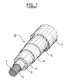
- la figure 1 est une vue en perspective éclatée d'un câble d'énergie incorporant deux écrans semi-conducteurs selon l'invention
- la figure 2 est une vue en coupe transversale du câble de la figure 1
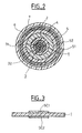
- la figure 3 est une vue en coupe d'un échantillon servant à effectuer l'essai dit de l'onde de pression.
- Figure 1 is an exploded perspective view of an energy cable incorporating two semiconductor screens according to the invention
- Figure 2 is a cross-sectional view of the cable of Figure 1
- Figure 3 is a sectional view of a sample for performing the so-called pressure wave test.
La figure 1 montre un câble 10 comprenant, disposés coaxialement de l'intérieur vers l'extérieur :
- une âme conductrice 1 formée d'un toron de conducteurs de cuivre 2
- un écran semi-conducteur intérieur 3 en contact
avec l'âme conductrice 1 - une couche d'isolation électrique 4 en un matériau diélectrique tel que le polyéthylène haute ou basse densité, le polyéthylène réticulé ou le terpolymère d'éthylène-propylène-diène à chaîne principale méthylène (EPDM)
- un écran semi-conducteur extérieur 5 en contact avec la couche d'isolation électrique 4
- un écran métallique de
protection 6, optionnel, constitué d'un ruban d'aluminium - une gaine extérieure de
protection 7 en un matériau tel que le polychlorure de vinyle, le polyéthylène ou un mélange de polymère et de charges ignifugeantes.
- a
conductive core 1 formed of a strand ofcopper conductors 2 - an
interior semiconductor screen 3 in contact with theconductive core 1 - an
electrical insulation layer 4 made of a dielectric material such as high or low density polyethylene, crosslinked polyethylene or ethylene-propylene-diene terpolymer with methylene main chain (EPDM) - an
external semiconductor screen 5 in contact with theelectrical insulation layer 4 - an optional
protective metal screen 6, consisting of an aluminum tape - an outer
protective sheath 7 made of a material such as polyvinyl chloride, polyethylene or a mixture of polymer and flame retardant fillers.
Selon l'invention, l'écran semi-conducteur intérieur 3 est un composite qui comprend (voir figure 2) une couche 31 de conductivité électrique volumique longitudinale élevée, typiquement supérieure à 0,1 S/m entre 20 et 90°C, et de préférence supérieure à 5 S/m à ces températures, en contact avec l'âme conductrice 1, et une couche 32 susceptible d'injecter une faible quantité de charges d'espace dans la couche d'isolation 4 après polarisation, de sorte que la quantité de charges d'espace injectées depuis l'écran 3 dans la couche d'isolation électrique 4 est typiquement inférieure à 200 nC entre 25 et 70°C, la couche 32 étant en contact avec la couche d'isolation électrique 4.According to the invention, the
Toujours selon l'invention, l'écran semi-conducteur extérieur 5 est un composite qui comprend une couche 51 de conductivité électrique volumique élevée, typiquement supérieure à 0,1 S/m entre 20 et 90°C, et de préférence supérieure à 5 S/m à ces températures, la couche 51 étant en contact avec l'écran métallique 6, et une couche 52 susceptible d'injecter une faible quantité de charges d'espace dans la couche d'isolation 4 après polarisation, de sorte que la quantité de charges d'espace injectées depuis l'écran 5 dans la couche d'isolation électrique 4 est typiquement inférieure à 200 nC entre 25 et 70°C, la couche 52 étant en contact avec la couche d'isolation électrique 4.Still according to the invention, the
Comme mentionné plus haut, les écrans semi-conducteurs 3 et 5 selon l'invention permettent à la fois d'obtenir une conductivité électrique satisfaisante au voisinage des éléments conducteurs du câble 10 afin d'assurer la fonction d'homogénéisation de la répartition du champ électrique, et de limiter l'injection de charges d'espace dans la couche d'isolation électrique 4 puisque les couches 32 et 52 des écrans semi-conducteurs 3 et 5 en contact avec cette dernière injectent une faible quantité de charges d'espace après polarisation.As mentioned above, the
Afin de montrer l'efficacité de l'invention, on a procédé à des mesures de charges d'espace par la méthode de l'onde de pression, en tant que telle connue, sur trois échantillons différents A, B et C, dont la structure de base est montrée en figure 3. Les épaisseurs des couches SC1 et SC2 de l'échantillon A sont doubles de celles des couches SC1 et SC2 des échantillons B et C.In order to show the effectiveness of the invention, space charge measurements were carried out by the pressure wave method, as known, on three different samples A, B and C, the basic structure is shown in figure 3. The thicknesses of the layers SC1 and SC2 of the sample A are double those of the layers SC1 and SC2 of the samples B and C.
Chacun de ces échantillons comprend une couche électriquement isolante I d'épaisseur 0,8 mm placée entre deux couches semi-conductrices SC1 et SC2 de compositions identiques.Each of these samples comprises an electrically insulating layer I of thickness 0.8 mm placed between two semiconductor layers SC1 and SC2 of identical compositions.
Dans l'échantillon A, les deux couches SC1 et SC2 sont des écrans semi-conducteurs composites selon l'invention constitués chacun d'une couche en un matériau de Composition 1 donnée ci-dessous, susceptible d'induire une forte quantité de charges d'espace et d'une couche en un matériau de Composition 2 donnée ci-dessous, induisant une faible quantité de charges d'espace dans la couche électriquement isolante I avec laquelle elle est en contact.In sample A, the two layers SC1 and SC2 are composite semiconductor screens according to the invention each consisting of a layer of a material of
- Polyéthylène basse densité (0,919 g/cm3) ayant un Melt Flow Index de 2 et une masse molaire moyenne en poids de 126 500 g/mol : 100 partsLow density polyethylene (0.919 g / cm 3 ) having a Melt Flow Index of 2 and a weight average molar mass of 126,500 g / mol: 100 parts
- SBS hydrogéné (copolymère séquencé, hydrogéné de styrène et de butadiène) : 20 partsHydrogenated SBS (block, hydrogenated copolymer of styrene and butadiene): 20 parts
- Noir au four ENSACO 250 G : 39 partsBlack in oven ENSACO 250 G: 39 parts
- Antioxydant : 0,25 partAntioxidant: 0.25 part
- Polyéthylène basse densité (0,919 g/cm3) ayant un Melt Flow Index de 2 et une masse molaire moyenne en poids de 126 500 g/mol : 100 partsLow density polyethylene (0.919 g / cm 3 ) having a Melt Flow Index of 2 and a weight average molar mass of 126,500 g / mol: 100 parts
- SBS hydrogéné : 20 partsSBS hydrogenated: 20 parts
- Noir d'acétylène DENKA : 39 partsDENKA acetylene black: 39 parts
- Antioxydant : 0,25 partAntioxidant: 0.25 part
Dans l'échantillon B, les deux couches SC1 et SC2 sont constituées uniquement d'un matériau de Composition 2 ci-dessus.In sample B, the two layers SC1 and SC2 consist only of a material of
Dans l'échantillon C, les deux couches SC1 et SC2 sont constituées uniquement d'un matériau de Composition 1 ci-dessus.In sample C, the two layers SC1 and SC2 consist solely of a material of
Il est important d'insister sur le fait que les compositions 1 et 2 ci-dessus ont été choisies afin de pouvoir effectuer des comparaisons de quantités de charges d'espace injectées, et ce indépendamment de leur conductivité électrique.It is important to insist on the fact that the
L'essai mis en oeuvre, dit essai de l'onde de pression, consiste à envoyer le faisceau d'un laser YAG sur l'échantillon testé, dont chaque écran semi-conducteur constitue une électrode (+) et (-). Ce faisceau absorbé en surface de l'électrode (-) décompose cette surface par pyrolyse, et les gaz émis provoquent une onde de pression qui traverse l'échantillon, provoquant un déplacement de charges d'espace et l'apparition de charges images aux électrodes, donnant lieu au signal mesuré. Le traitement de ce signal donne une indication sur la répartition du champ électrique et sur la densité de charge volumique dans l'échantillon.The test implemented, called the pressure wave test, consists in sending the beam of a YAG laser onto the test sample, each semiconductor screen of which constitutes an electrode (+) and (-). This beam absorbed on the surface of the electrode (-) decomposes this surface by pyrolysis, and the gases emitted cause a pressure wave which crosses the sample, causing a displacement of space charges and the appearance of image charges at the electrodes. , giving rise to the measured signal. The processing of this signal gives an indication of the distribution of the electric field and of the volume charge density in the sample.
Les valeurs mises en évidence lors de cet essai sur les échantillons testés sont la densité maximale D+ de charges positives dans la couche isolante I, la densité maximale D- de charges négatives dans la couche isolante I et la quantité totale QT de charges dans la couche isolante I (en fait son image).The values highlighted during this test on the samples tested are the maximum density D + of positive charges in the insulating layer I, the maximum density D - of negative charges in the insulating layer I and the total quantity Q T of charges in the insulating layer I (in fact its image).
Le Tableau 1 ci-dessous donne les résultats obtenus hors champ appliqué, après polarisation des échantillons durant 4 heures sous une tension électrique continue de +40 kV à température ambiante (25°C).
Ce tableau met en évidence le fait que, à température ambiante, un écran semi-conducteur selon l'invention injecte 19 fois moins de charges d'espace que la couche entraînant la plus forte injection seule (échantillon C), mais également 15 fois moins que celle présentant la plus faible injection de charges d'espace seule (échantillon B). Ce résultat est donc tout à fait surprenant.This table highlights the fact that, at room temperature, a semiconductor screen according to the invention injects 19 times less space charges than the layer causing the highest injection alone (sample C), but also 15 times less than the one with the lowest injection of space charges alone (sample B). This result is therefore quite surprising.
Il montre que l'on peut choisir pour la première couche d'un écran semi-conducteur selon l'invention, un matériau à forte, moyenne ou faible injection de charges d'espace, du moment que ses caractéristiques de conductivité électrique sont satisfaisantes.It shows that one can choose for the first layer of a semiconductor screen according to the invention, a material with high, medium or low injection of space charges, as long as its electrical conductivity characteristics are satisfactory.
Le Tableau 2 ci-dessous donne les résultats obtenus après polarisation des échantillons durant 4 heures sous une tension électrique continue de +40 kV à 70°C.
Le Tableau 2 montre que les résultats obtenus à température ambiante sont également valables à température élevée.Table 2 shows that the results obtained at room temperature are also valid at high temperature.
On a procédé à d'autres mesures, dans les mêmes conditions que celles décrites ci-dessus, sur des échantillons D, E, F et G, dont la structure de base est également celle de la figure 3.Other measurements were carried out, under the same conditions as those described above, on samples D, E, F and G, the basic structure of which is also that of FIG. 3.
Dans l'échantillon D, les deux couches SC1 et SC2 sont des écrans semi-conducteurs composites selon l'invention constitués chacun d'une couche en un matériau de Composition 3 donnée ci-dessous, susceptible d'induire une forte quantité de charges d'espace, et d'une couche en un matériau de Composition 4 donnée ci-dessous, induisant une faible quantité de charges d'espace dans la couche électriquement isolante I avec laquelle elle est en contact.In sample D, the two layers SC1 and SC2 are composite semiconductor screens according to the invention each consisting of a layer of a material of
- Polyéthylène basse densité (0,920 g/cm3) ayant un Melt Flow Index de 2 et une masse molaire moyenne en poids de 212 000 g/mol : 100 partsLow density polyethylene (0.920 g / cm 3 ) having a Melt Flow Index of 2 and a weight average molar mass of 212,000 g / mol: 100 parts
- SBS hydrogéné : 20 partsSBS hydrogenated: 20 parts
- Noir au four ENSACO 250G : 39 partsENSACO 250G baked black: 39 parts
- Antioxydant : 0,25 partAntioxidant: 0.25 part
- Polyéthylène basse densité (0,920 g/cm3) ayant un Melt Flow Index de 2 et une masse molaire moyenne en poids de 212 000 g/mol : 100 partsLow density polyethylene (0.920 g / cm 3 ) having a Melt Flow Index of 2 and a weight average molar mass of 212,000 g / mol: 100 parts
-
SBS hydrogéné : 20 parts ( A expliciter par les inventeurs) Hydrogenated SBS: 20 parts (
 To be explained by the inventors)
 - Noir d'acétylène DENKA : 39 partsDENKA acetylene black: 39 parts
- Antioxydant : 0,25 partAntioxidant: 0.25 part
Dans l'échantillon E, les deux couches SC1 et SC2 sont constituées uniquement d'un matériau de Composition 4 ci-dessus.In sample E, the two layers SC1 and SC2 consist only of a material of
Dans l'échantillon F, les deux couches SC1 et SC2 sont constituées uniquement d'un matériau de Composition 3 ci-dessusIn sample F, the two layers SC1 and SC2 consist only of a material of
Dans l'échantillon G, les deux couches SC1 et SC2 sont constituées uniquement d'un matériau semi-conducteur à forte injection de charges d'espace et conductivité électrique élevée du commerce, à base d'un mélange de polyéthylène et de copolymère d'éthylène et d'acétate de vinyl.In sample G, the two layers SC1 and SC2 consist solely of a semiconductor material with high injection of space charges and high commercial electrical conductivity, based on a mixture of polyethylene and copolymer of ethylene and vinyl acetate.
A noter que pour tous les échantillons D à G, les épaisseurs des couches SC1 et SC2 sont identiques.Note that for all samples D to G, the thicknesses of the layers SC1 and SC2 are identical.
Ici encore, il est important d'insister sur le fait que les compositions 3 à 5 ci-dessus ont été choisies afin de pouvoir effectuer des comparaisons de quantités de charges d'espace injectées, et ce indépendamment de leur conductivité électrique.Here again, it is important to insist on the fact that the
Le Tableau 3 ci-dessous donne les résultats obtenus hors champ appliqué, après polarisation des échantillons durant 4 heures sous une tension électrique continue de +40 kV à température ambiante (25°C).
Les résultats montrés au Tableau 3 amènent aux mêmes conclusions qualitatives que ceux du Tableau 1.The results shown in Table 3 lead to the same qualitative conclusions as those of Table 1.
Le Tableau 4 ci-dessous donne les résultats obtenus après polarisation des échantillons durant 4 heures sous une tension électrique continue de +40 kV à 70°C.
Les résultats montrés au Tableau 4 amènent aux mêmes conclusions qualitatives que ceux du Tableau 2.The results shown in Table 4 lead to the same qualitative conclusions as those of Table 2.
On ne rentrera pas ici dans les détails du procédé de fabrication d'un câble selon l'invention. On indique simplement qu'un écran selon l'invention peut être obtenu par co-extrusion de ses deux couches constitutives dans un dispositif adapté, bien connu de l'homme de l'art.We will not go into the details of the process for manufacturing a cable according to the invention here. It is simply indicated that a screen according to the invention can be obtained by co-extrusion of its two constituent layers in a suitable device, well known to those skilled in the art.
Bien entendu, l'invention n'est pas limitée au mode de réalisation qui vient d'être décrit.Of course, the invention is not limited to the embodiment which has just been described.
De même, la structure de câble d'énergie décrite ne l'est qu'à titre d'exemple, et un câble d'énergie selon l'invention peut ne comprendre qu'un écran semi-conducteur selon l'invention, par exemple l'écran semi-conducteur intérieur seulement ou l'écran semi-conducteur extérieur seulement. En outre, le câble selon l'invention peut comprendre d'autres types d'écrans métalliques de protection, par exemple un écran en aluminium contrecollé ou soudé.Similarly, the energy cable structure described is only for example, and an energy cable according to the invention may comprise only a semiconductor screen according to the invention, for example the interior semiconductor screen only or the exterior semiconductor screen only. In addition, the cable according to the invention may include other types of metallic protective screens, for example a laminated or welded aluminum screen.
En outre, la structure de protection qui comporte l'écran métallique et la gaine extérieure peut également comporter d'autres éléments de protection tels que notamment une bande de protection gonflante en présence d'eau. Une telle bande de protection peut être interposée entre l'écran semi-conducteur extérieur et l'écran métallique de protection. Elle assure elle-même ou est associée à des moyens conducteurs assurant la continuité électrique entre l'écran semi-conducteur extérieur et l'écran métallique.In addition, the protective structure which comprises the metal screen and the outer sheath may also include other protective elements such as in particular a swelling protective strip in the presence of water. Such a protective strip can be interposed between the outer semiconductor screen and the metal protective screen. It provides itself or is associated with conductive means ensuring electrical continuity between the outer semiconductor screen and the metal screen.
Par ailleurs, les matériaux indiqués pour les différents éléments des câbles selon l'invention le sont à titre indicatif, et peuvent bien entendu être remplacés par des matériaux équivalents qui sont à la portée de l'homme de l'art.Furthermore, the materials indicated for the various elements of the cables according to the invention are for information only, and can of course be replaced by equivalent materials which are within the reach of those skilled in the art.
Ainsi notamment, l'homme du métier pourra faire varier les compositions données plus haut à titre d'exemple, de la manière suivante :
- la teneur massique en styrène dans la matrice polymère peut être de 0,1 à 20 %, préférentiellement de 1 à 10 %,
- la charge conductrice peut être du noir de carbone, de préférence du type « acétylène » qui est plus propre que les noirs de carbone du type « furnace » (ou noirs au four),
- la teneur massique en noir de carbone (par rapport à la matrice) peut être de 15 à 40% préférentiellement de 20 à 30 %,
- l'anti-oxydant utilisé est l'Irganox 1010 ; la teneur massique en antioxydant est de 0,1 à 0,2 %, préférentiellement de 0,15 %.
- the mass content of styrene in the polymer matrix can be from 0.1 to 20%, preferably from 1 to 10%,
- the conductive filler can be carbon black, preferably of the “acetylene” type which is cleaner than carbon blacks of the “furnace” type (or oven blacks),
- the mass content of carbon black (relative to the matrix) may be from 15 to 40%, preferably from 20 to 30%,
- the antioxidant used is Irganox 1010; the mass content of antioxidant is 0.1 to 0.2%, preferably 0.15%.
Enfin, on pourra remplacer tout moyen par un moyen équivalent sans sortir du cadre de l'invention.Finally, any means can be replaced by equivalent means without departing from the scope of the invention.
Claims (14)
caractérisé en ce que la deuxième desdites couches (32, 52) est destinée à être placée au contact d'une couche d'isolation électrique (4) dudit câble d'énergie et est telle que la quantité de charges d'espace susceptibles d'être injectées depuis ladite deuxième couche (32, 52) dans ladite couche d'isolation électrique (4) est faible, de sorte que la quantité de charges d'espace susceptibles d'être injectées depuis ledit écran semi-conducteur (3, 5) dans ladite couche d'isolation (4) est inférieure à la quantité de charges d'espace susceptibles d'être injectées depuis ladite deuxième couche (32, 52) seule dans ladite couche d'isolation électrique (4), ladite deuxième couche (32, 52) formant une barrière limitant l'injection de charges d'espace dans ladite couche d'isolation électrique (4).Semiconductor screen (3, 5) for power cable comprising two layers (31, 32; 51, 52), each of said layers comprising a polymer matrix in which a conductive filler is dispersed, a first of said layers (31, 51 ) having a longitudinal volume electrical conductivity greater than 0.1 S / m between 20 and 90 ° C,
characterized in that the second of said layers (32, 52) is intended to be placed in contact with an electrically insulating layer (4) of said power cable and is such that the amount of space charges capable of be injected from said second layer (32, 52) into said electrical insulation layer (4) is low, so that the amount of space charges that can be injected from said semiconductor screen (3, 5) in said insulation layer (4) is less than the amount of space charges capable of being injected from said second layer (32, 52) alone in said electrical insulation layer (4), said second layer (32 , 52) forming a barrier limiting the injection of space charges into said layer of electrical insulation (4).
lesdites deuxièmes couches (32, 52) desdits écrans semi-conducteurs intérieur et extérieur (3, 5) étant en contact avec ladite couche d'isolation électrique (4).Power cable according to Claim 11, characterized in that it comprises, arranged coaxially and from the inside to the outside:
said second layers (32, 52) of said interior and exterior semiconductor screens (3, 5) being in contact with said electrical insulation layer (4).
Applications Claiming Priority (2)
| Application Number | Priority Date | Filing Date | Title |
|---|---|---|---|
| FR0110045A FR2827999B1 (en) | 2001-07-25 | 2001-07-25 | SEMICONDUCTOR SCREEN FOR ENERGY CABLE |
| FR0110045 | 2001-07-25 |
Publications (2)
| Publication Number | Publication Date |
|---|---|
| EP1280167A1 true EP1280167A1 (en) | 2003-01-29 |
| EP1280167B1 EP1280167B1 (en) | 2009-01-07 |
Family
ID=8865972
Family Applications (1)
| Application Number | Title | Priority Date | Filing Date |
|---|---|---|---|
| EP02291796A Expired - Lifetime EP1280167B1 (en) | 2001-07-25 | 2002-07-17 | Semiconductive screen for power cable |
Country Status (7)
| Country | Link |
|---|---|
| EP (1) | EP1280167B1 (en) |
| JP (1) | JP4630519B2 (en) |
| AT (1) | ATE420443T1 (en) |
| DE (1) | DE60230698D1 (en) |
| DK (1) | DK1280167T3 (en) |
| ES (1) | ES2320202T3 (en) |
| FR (1) | FR2827999B1 (en) |
Cited By (5)
| Publication number | Priority date | Publication date | Assignee | Title |
|---|---|---|---|---|
| US8361606B2 (en) * | 2004-07-02 | 2013-01-29 | Ticona Gmbh | Composite comprising at least one hard component and at least one soft component |
| CN103093868A (en) * | 2013-01-28 | 2013-05-08 | 东莞市瀛通电线有限公司 | Alloy filler tensile earphone wire |
| WO2013182829A1 (en) * | 2012-06-08 | 2013-12-12 | Nexans | Device comprising a space charge trapping layer |
| CN103915201A (en) * | 2013-09-25 | 2014-07-09 | 安徽省高沟电缆有限公司 | Control power cable used for petrochemical industry |
| CN107077918A (en) * | 2014-10-17 | 2017-08-18 | 3M创新有限公司 | Dielectric substance with enhanced breakdown strength |
Families Citing this family (2)
| Publication number | Priority date | Publication date | Assignee | Title |
|---|---|---|---|---|
| KR101161360B1 (en) * | 2010-07-13 | 2012-06-29 | 엘에스전선 주식회사 | DC Power Cable Having Reduced Space Charge Effect |
| CN105023637B (en) * | 2015-08-15 | 2017-05-31 | 国网新疆电力公司塔城供电公司 | The high-tension cable of electromagnetism interference |
Citations (2)
| Publication number | Priority date | Publication date | Assignee | Title |
|---|---|---|---|---|
| GB2165689A (en) * | 1984-10-08 | 1986-04-16 | Ass Elect Ind | High voltage cables |
| GB2252866A (en) * | 1991-01-03 | 1992-08-19 | Phillips Cables Ltd | Flexible electrically insulated electric conductor |
Family Cites Families (12)
| Publication number | Priority date | Publication date | Assignee | Title |
|---|---|---|---|---|
| JPS50116983A (en) * | 1974-02-28 | 1975-09-12 | ||
| JPS53137676U (en) * | 1977-04-05 | 1978-10-31 | ||
| JPS6063813A (en) * | 1983-09-19 | 1985-04-12 | 日立電線株式会社 | Semiconductive composition for power cable |
| JPS636707A (en) * | 1986-06-27 | 1988-01-12 | 昭和電線電纜株式会社 | Crosslinked polyolefin insulated cable |
| JPS6424307A (en) * | 1987-07-21 | 1989-01-26 | Fujikura Ltd | Dc power cable |
| JPS6424308A (en) * | 1987-07-21 | 1989-01-26 | Fujikura Ltd | Dc power cable |
| DK0507676T3 (en) * | 1991-04-02 | 1996-08-05 | Alcatel Cable | Semiconductor shielding material |
| FR2710183B3 (en) * | 1993-09-17 | 1995-10-13 | Alcatel Cable | Power cable with improved dielectric strength. |
| JPH08306243A (en) * | 1995-05-08 | 1996-11-22 | Fujikura Ltd | Power cable and connecting tape |
| JPH1079205A (en) * | 1996-09-04 | 1998-03-24 | Fujikura Ltd | Power cable and power equipment |
| JPH10255561A (en) * | 1997-03-06 | 1998-09-25 | Showa Electric Wire & Cable Co Ltd | Dc power cable |
| JPH11260158A (en) * | 1998-03-09 | 1999-09-24 | Showa Electric Wire & Cable Co Ltd | Dc power cable |
-
2001
- 2001-07-25 FR FR0110045A patent/FR2827999B1/en not_active Expired - Fee Related
-
2002
- 2002-07-17 EP EP02291796A patent/EP1280167B1/en not_active Expired - Lifetime
- 2002-07-17 DK DK02291796T patent/DK1280167T3/en active
- 2002-07-17 AT AT02291796T patent/ATE420443T1/en not_active IP Right Cessation
- 2002-07-17 ES ES02291796T patent/ES2320202T3/en not_active Expired - Lifetime
- 2002-07-17 DE DE60230698T patent/DE60230698D1/en not_active Expired - Lifetime
- 2002-07-24 JP JP2002215399A patent/JP4630519B2/en not_active Expired - Fee Related
Patent Citations (2)
| Publication number | Priority date | Publication date | Assignee | Title |
|---|---|---|---|---|
| GB2165689A (en) * | 1984-10-08 | 1986-04-16 | Ass Elect Ind | High voltage cables |
| GB2252866A (en) * | 1991-01-03 | 1992-08-19 | Phillips Cables Ltd | Flexible electrically insulated electric conductor |
Cited By (9)
| Publication number | Priority date | Publication date | Assignee | Title |
|---|---|---|---|---|
| US8361606B2 (en) * | 2004-07-02 | 2013-01-29 | Ticona Gmbh | Composite comprising at least one hard component and at least one soft component |
| WO2013182829A1 (en) * | 2012-06-08 | 2013-12-12 | Nexans | Device comprising a space charge trapping layer |
| FR2991808A1 (en) * | 2012-06-08 | 2013-12-13 | Nexans | DEVICE COMPRISING A TRAPPER LAYER OF SPACE LOADS |
| US9748758B2 (en) | 2012-06-08 | 2017-08-29 | Nexans | Device comprising a space charge trapping layer |
| CN103093868A (en) * | 2013-01-28 | 2013-05-08 | 东莞市瀛通电线有限公司 | Alloy filler tensile earphone wire |
| CN103915201A (en) * | 2013-09-25 | 2014-07-09 | 安徽省高沟电缆有限公司 | Control power cable used for petrochemical industry |
| CN107077918A (en) * | 2014-10-17 | 2017-08-18 | 3M创新有限公司 | Dielectric substance with enhanced breakdown strength |
| US20170250008A1 (en) * | 2014-10-17 | 2017-08-31 | 3M Innovative Properties Company | Dielectric material with enhanced breakdown strength |
| US10121570B2 (en) * | 2014-10-17 | 2018-11-06 | 3M Innovative Properties Company | Dielectric material with enhanced breakdown strength |
Also Published As
| Publication number | Publication date |
|---|---|
| ES2320202T3 (en) | 2009-05-20 |
| DE60230698D1 (en) | 2009-02-26 |
| JP2003051218A (en) | 2003-02-21 |
| JP4630519B2 (en) | 2011-02-09 |
| ATE420443T1 (en) | 2009-01-15 |
| EP1280167B1 (en) | 2009-01-07 |
| DK1280167T3 (en) | 2009-05-04 |
| FR2827999B1 (en) | 2003-10-17 |
| FR2827999A1 (en) | 2003-01-31 |
Similar Documents
| Publication | Publication Date | Title |
|---|---|---|
| EP1128395B1 (en) | High and extra-high voltage d.c. power cable | |
| EP2224459B1 (en) | High voltage electrical cable | |
| EP0068307B1 (en) | Electrochemical generators comprising a solid electrolyte constituted by a cation conducting vitreous composition | |
| WO2011039474A1 (en) | Medium- or high-voltage electric cable | |
| FR2501897A1 (en) | HIGH VOLTAGE ISOLATED CABLE | |
| CA2521447A1 (en) | Electrical cables | |
| FR2980622A1 (en) | ELECTRIC ELEMENT COMPRISING A LAYER OF A POLYMERIC MATERIAL WITH A GRADIENT OF ELECTRICAL CONDUCTIVITY | |
| EP2765581B1 (en) | Electric cable resistant to partial discharges | |
| EP0660483B1 (en) | Device for joining power cables | |
| EP1280167B1 (en) | Semiconductive screen for power cable | |
| EP2136376B1 (en) | High-voltage power cable | |
| EP0644558B1 (en) | Câble insulative structure | |
| EP0645781B1 (en) | Power cable with improved dielectric strength | |
| EP3764372A1 (en) | Cable comprising a fire-resistant layer | |
| WO2019086685A1 (en) | Cable end and corresponding manufacturing method | |
| JPH103823A (en) | Direct current power cable insulated by cross-linked polyethylene | |
| EP2535901B1 (en) | Medium- or high-voltage cable with polyolefin sheath containing mineral fillers | |
| EP2498264B1 (en) | Medium- or high-voltage electrical cable | |
| EP4092689A1 (en) | Electric cable limiting partial discharges | |
| EP3671768A1 (en) | Electric cable resistant to water trees | |
| FR2601184A1 (en) | Electrical safety (security) cable which is fire-resistant and does not propagate fire, and the process for manufacturing it | |
| EP3544025A1 (en) | Electric cable including an easily peelable polymer layer | |
| FR2654867A1 (en) | Electrical cable capable of providing a minimum electrical service during a fire, even when directly exposed to a flame | |
| FR2508239A2 (en) | Electrochemical cell with cation conductive vitreous electrolyte - formed by powder compaction on cathode with lithium disc superimposed | |
| EP3503125A1 (en) | Cable comprising at least one metallic layer of carbon material |
Legal Events
| Date | Code | Title | Description |
|---|---|---|---|
| PUAI | Public reference made under article 153(3) epc to a published international application that has entered the european phase |
Free format text: ORIGINAL CODE: 0009012 |
|
| AK | Designated contracting states |
Designated state(s): AT BE BG CH CY CZ DE DK EE ES FI FR GB GR IE IT LI LU MC NL PT SE SK TR |
|
| AX | Request for extension of the european patent |
Extension state: AL LT LV MK RO SI |
|
| 17P | Request for examination filed |
Effective date: 20030729 |
|
| AKX | Designation fees paid |
Designated state(s): AT BE BG CH CY CZ DE DK EE ES FI FR GB GR IE IT LI LU MC NL PT SE SK TR |
|
| REG | Reference to a national code |
Ref country code: SE Ref legal event code: TRGR |
|
| GRAP | Despatch of communication of intention to grant a patent |
Free format text: ORIGINAL CODE: EPIDOSNIGR1 |
|
| GRAS | Grant fee paid |
Free format text: ORIGINAL CODE: EPIDOSNIGR3 |
|
| GRAA | (expected) grant |
Free format text: ORIGINAL CODE: 0009210 |
|
| AK | Designated contracting states |
Kind code of ref document: B1 Designated state(s): AT BE BG CH CY CZ DE DK EE ES FI FR GB GR IE IT LI LU MC NL PT SE SK TR |
|
| REG | Reference to a national code |
Ref country code: GB Ref legal event code: FG4D Free format text: NOT ENGLISH |
|
| REG | Reference to a national code |
Ref country code: CH Ref legal event code: EP |
|
| REG | Reference to a national code |
Ref country code: IE Ref legal event code: FG4D Free format text: LANGUAGE OF EP DOCUMENT: FRENCH |
|
| REF | Corresponds to: |
Ref document number: 60230698 Country of ref document: DE Date of ref document: 20090226 Kind code of ref document: P |
|
| REG | Reference to a national code |
Ref country code: DK Ref legal event code: T3 |
|
| REG | Reference to a national code |
Ref country code: ES Ref legal event code: FG2A Ref document number: 2320202 Country of ref document: ES Kind code of ref document: T3 |
|
| PG25 | Lapsed in a contracting state [announced via postgrant information from national office to epo] |
Ref country code: NL Free format text: LAPSE BECAUSE OF FAILURE TO SUBMIT A TRANSLATION OF THE DESCRIPTION OR TO PAY THE FEE WITHIN THE PRESCRIBED TIME-LIMIT Effective date: 20090107 |
|
| NLV1 | Nl: lapsed or annulled due to failure to fulfill the requirements of art. 29p and 29m of the patents act | ||
| PG25 | Lapsed in a contracting state [announced via postgrant information from national office to epo] |
Ref country code: FI Free format text: LAPSE BECAUSE OF FAILURE TO SUBMIT A TRANSLATION OF THE DESCRIPTION OR TO PAY THE FEE WITHIN THE PRESCRIBED TIME-LIMIT Effective date: 20090107 |
|
| REG | Reference to a national code |
Ref country code: IE Ref legal event code: FD4D |
|
| PG25 | Lapsed in a contracting state [announced via postgrant information from national office to epo] |
Ref country code: AT Free format text: LAPSE BECAUSE OF FAILURE TO SUBMIT A TRANSLATION OF THE DESCRIPTION OR TO PAY THE FEE WITHIN THE PRESCRIBED TIME-LIMIT Effective date: 20090107 Ref country code: PT Free format text: LAPSE BECAUSE OF FAILURE TO SUBMIT A TRANSLATION OF THE DESCRIPTION OR TO PAY THE FEE WITHIN THE PRESCRIBED TIME-LIMIT Effective date: 20090608 |
|
| PG25 | Lapsed in a contracting state [announced via postgrant information from national office to epo] |
Ref country code: EE Free format text: LAPSE BECAUSE OF FAILURE TO SUBMIT A TRANSLATION OF THE DESCRIPTION OR TO PAY THE FEE WITHIN THE PRESCRIBED TIME-LIMIT Effective date: 20090107 Ref country code: CZ Free format text: LAPSE BECAUSE OF FAILURE TO SUBMIT A TRANSLATION OF THE DESCRIPTION OR TO PAY THE FEE WITHIN THE PRESCRIBED TIME-LIMIT Effective date: 20090107 Ref country code: IE Free format text: LAPSE BECAUSE OF FAILURE TO SUBMIT A TRANSLATION OF THE DESCRIPTION OR TO PAY THE FEE WITHIN THE PRESCRIBED TIME-LIMIT Effective date: 20090107 |
|
| PLBE | No opposition filed within time limit |
Free format text: ORIGINAL CODE: 0009261 |
|
| STAA | Information on the status of an ep patent application or granted ep patent |
Free format text: STATUS: NO OPPOSITION FILED WITHIN TIME LIMIT |
|
| PG25 | Lapsed in a contracting state [announced via postgrant information from national office to epo] |
Ref country code: SK Free format text: LAPSE BECAUSE OF FAILURE TO SUBMIT A TRANSLATION OF THE DESCRIPTION OR TO PAY THE FEE WITHIN THE PRESCRIBED TIME-LIMIT Effective date: 20090107 |
|
| 26N | No opposition filed |
Effective date: 20091008 |
|
| PG25 | Lapsed in a contracting state [announced via postgrant information from national office to epo] |
Ref country code: BG Free format text: LAPSE BECAUSE OF FAILURE TO SUBMIT A TRANSLATION OF THE DESCRIPTION OR TO PAY THE FEE WITHIN THE PRESCRIBED TIME-LIMIT Effective date: 20090407 |
|
| BERE | Be: lapsed |
Owner name: NEXANS Effective date: 20090731 |
|
| PG25 | Lapsed in a contracting state [announced via postgrant information from national office to epo] |
Ref country code: MC Free format text: LAPSE BECAUSE OF NON-PAYMENT OF DUE FEES Effective date: 20090731 |
|
| PG25 | Lapsed in a contracting state [announced via postgrant information from national office to epo] |
Ref country code: BE Free format text: LAPSE BECAUSE OF NON-PAYMENT OF DUE FEES Effective date: 20090731 |
|
| PG25 | Lapsed in a contracting state [announced via postgrant information from national office to epo] |
Ref country code: GR Free format text: LAPSE BECAUSE OF FAILURE TO SUBMIT A TRANSLATION OF THE DESCRIPTION OR TO PAY THE FEE WITHIN THE PRESCRIBED TIME-LIMIT Effective date: 20090408 |
|
| PG25 | Lapsed in a contracting state [announced via postgrant information from national office to epo] |
Ref country code: LU Free format text: LAPSE BECAUSE OF NON-PAYMENT OF DUE FEES Effective date: 20090717 |
|
| PG25 | Lapsed in a contracting state [announced via postgrant information from national office to epo] |
Ref country code: TR Free format text: LAPSE BECAUSE OF FAILURE TO SUBMIT A TRANSLATION OF THE DESCRIPTION OR TO PAY THE FEE WITHIN THE PRESCRIBED TIME-LIMIT Effective date: 20090107 |
|
| PG25 | Lapsed in a contracting state [announced via postgrant information from national office to epo] |
Ref country code: CY Free format text: LAPSE BECAUSE OF FAILURE TO SUBMIT A TRANSLATION OF THE DESCRIPTION OR TO PAY THE FEE WITHIN THE PRESCRIBED TIME-LIMIT Effective date: 20090107 |
|
| PGFP | Annual fee paid to national office [announced via postgrant information from national office to epo] |
Ref country code: ES Payment date: 20110726 Year of fee payment: 10 |
|
| REG | Reference to a national code |
Ref country code: ES Ref legal event code: FD2A Effective date: 20131021 |
|
| PG25 | Lapsed in a contracting state [announced via postgrant information from national office to epo] |
Ref country code: ES Free format text: LAPSE BECAUSE OF NON-PAYMENT OF DUE FEES Effective date: 20120718 |
|
| PGFP | Annual fee paid to national office [announced via postgrant information from national office to epo] |
Ref country code: CH Payment date: 20130719 Year of fee payment: 12 Ref country code: DK Payment date: 20130719 Year of fee payment: 12 |
|
| PGFP | Annual fee paid to national office [announced via postgrant information from national office to epo] |
Ref country code: GB Payment date: 20130719 Year of fee payment: 12 |
|
| REG | Reference to a national code |
Ref country code: DK Ref legal event code: EBP Effective date: 20140731 |
|
| REG | Reference to a national code |
Ref country code: CH Ref legal event code: PL |
|
| GBPC | Gb: european patent ceased through non-payment of renewal fee |
Effective date: 20140717 |
|
| PG25 | Lapsed in a contracting state [announced via postgrant information from national office to epo] |
Ref country code: CH Free format text: LAPSE BECAUSE OF NON-PAYMENT OF DUE FEES Effective date: 20140731 Ref country code: LI Free format text: LAPSE BECAUSE OF NON-PAYMENT OF DUE FEES Effective date: 20140731 |
|
| PG25 | Lapsed in a contracting state [announced via postgrant information from national office to epo] |
Ref country code: GB Free format text: LAPSE BECAUSE OF NON-PAYMENT OF DUE FEES Effective date: 20140717 |
|
| REG | Reference to a national code |
Ref country code: FR Ref legal event code: PLFP Year of fee payment: 14 |
|
| PG25 | Lapsed in a contracting state [announced via postgrant information from national office to epo] |
Ref country code: DK Free format text: LAPSE BECAUSE OF NON-PAYMENT OF DUE FEES Effective date: 20140731 |
|
| PGFP | Annual fee paid to national office [announced via postgrant information from national office to epo] |
Ref country code: FR Payment date: 20150626 Year of fee payment: 14 |
|
| PGFP | Annual fee paid to national office [announced via postgrant information from national office to epo] |
Ref country code: DE Payment date: 20150721 Year of fee payment: 14 |
|
| PGFP | Annual fee paid to national office [announced via postgrant information from national office to epo] |
Ref country code: SE Payment date: 20150721 Year of fee payment: 14 |
|
| PGFP | Annual fee paid to national office [announced via postgrant information from national office to epo] |
Ref country code: IT Payment date: 20150727 Year of fee payment: 14 |
|
| REG | Reference to a national code |
Ref country code: DE Ref legal event code: R119 Ref document number: 60230698 Country of ref document: DE |
|
| REG | Reference to a national code |
Ref country code: SE Ref legal event code: EUG |
|
| PG25 | Lapsed in a contracting state [announced via postgrant information from national office to epo] |
Ref country code: DE Free format text: LAPSE BECAUSE OF NON-PAYMENT OF DUE FEES Effective date: 20170201 Ref country code: FR Free format text: LAPSE BECAUSE OF NON-PAYMENT OF DUE FEES Effective date: 20160801 Ref country code: SE Free format text: LAPSE BECAUSE OF NON-PAYMENT OF DUE FEES Effective date: 20160718 |
|
| REG | Reference to a national code |
Ref country code: FR Ref legal event code: ST Effective date: 20170331 |
|
| PG25 | Lapsed in a contracting state [announced via postgrant information from national office to epo] |
Ref country code: IT Free format text: LAPSE BECAUSE OF NON-PAYMENT OF DUE FEES Effective date: 20160717 |