EP1279914B1 - Verfahren zur Vorbereitung von im Elektroofen zuzuführenden Eisenschrott und Vorrichtung zur Durchführung des Verfahrens - Google Patents
Verfahren zur Vorbereitung von im Elektroofen zuzuführenden Eisenschrott und Vorrichtung zur Durchführung des Verfahrens Download PDFInfo
- Publication number
- EP1279914B1 EP1279914B1 EP20010117639 EP01117639A EP1279914B1 EP 1279914 B1 EP1279914 B1 EP 1279914B1 EP 20010117639 EP20010117639 EP 20010117639 EP 01117639 A EP01117639 A EP 01117639A EP 1279914 B1 EP1279914 B1 EP 1279914B1
- Authority
- EP
- European Patent Office
- Prior art keywords
- gases
- chamber
- scrap
- reheating chamber
- reheating
- Prior art date
- Legal status (The legal status is an assumption and is not a legal conclusion. Google has not performed a legal analysis and makes no representation as to the accuracy of the status listed.)
- Expired - Lifetime
Links
- 238000000034 method Methods 0.000 title claims abstract description 36
- XEEYBQQBJWHFJM-UHFFFAOYSA-N Iron Chemical compound [Fe] XEEYBQQBJWHFJM-UHFFFAOYSA-N 0.000 title claims abstract description 18
- 238000009628 steelmaking Methods 0.000 title claims abstract description 16
- 229910052742 iron Inorganic materials 0.000 title claims abstract description 9
- 239000007789 gas Substances 0.000 claims abstract description 71
- 238000003303 reheating Methods 0.000 claims abstract description 57
- 230000001172 regenerating effect Effects 0.000 claims abstract description 16
- UGFAIRIUMAVXCW-UHFFFAOYSA-N Carbon monoxide Chemical compound [O+]#[C-] UGFAIRIUMAVXCW-UHFFFAOYSA-N 0.000 claims abstract description 7
- 239000003546 flue gas Substances 0.000 claims abstract description 7
- 238000012544 monitoring process Methods 0.000 claims description 6
- 239000000463 material Substances 0.000 claims description 5
- 238000009825 accumulation Methods 0.000 claims description 4
- 238000009826 distribution Methods 0.000 claims description 4
- 239000000428 dust Substances 0.000 claims description 4
- 230000014759 maintenance of location Effects 0.000 claims description 2
- 238000001514 detection method Methods 0.000 claims 2
- 238000004868 gas analysis Methods 0.000 claims 1
- 230000000717 retained effect Effects 0.000 abstract 1
- 238000004519 manufacturing process Methods 0.000 description 12
- 239000003344 environmental pollutant Substances 0.000 description 6
- 231100000719 pollutant Toxicity 0.000 description 6
- 238000010438 heat treatment Methods 0.000 description 5
- 238000002844 melting Methods 0.000 description 5
- 230000008018 melting Effects 0.000 description 5
- 229910000831 Steel Inorganic materials 0.000 description 4
- 238000005259 measurement Methods 0.000 description 4
- 239000010959 steel Substances 0.000 description 4
- 238000010891 electric arc Methods 0.000 description 3
- 239000000446 fuel Substances 0.000 description 3
- 238000005201 scrubbing Methods 0.000 description 3
- 238000012986 modification Methods 0.000 description 2
- 230000004048 modification Effects 0.000 description 2
- 230000009467 reduction Effects 0.000 description 2
- 239000000126 substance Substances 0.000 description 2
- 238000012546 transfer Methods 0.000 description 2
- 150000004945 aromatic hydrocarbons Chemical class 0.000 description 1
- 230000015556 catabolic process Effects 0.000 description 1
- 239000000567 combustion gas Substances 0.000 description 1
- 238000002485 combustion reaction Methods 0.000 description 1
- 238000007796 conventional method Methods 0.000 description 1
- 238000001816 cooling Methods 0.000 description 1
- 150000002013 dioxins Chemical class 0.000 description 1
- 229920001971 elastomer Polymers 0.000 description 1
- 230000008030 elimination Effects 0.000 description 1
- 238000003379 elimination reaction Methods 0.000 description 1
- 238000000605 extraction Methods 0.000 description 1
- 239000003517 fume Substances 0.000 description 1
- 230000000670 limiting effect Effects 0.000 description 1
- 238000012423 maintenance Methods 0.000 description 1
- 239000003921 oil Substances 0.000 description 1
- 239000004033 plastic Substances 0.000 description 1
- 229920003023 plastic Polymers 0.000 description 1
- 230000003134 recirculating effect Effects 0.000 description 1
- 239000005060 rubber Substances 0.000 description 1
- 230000003068 static effect Effects 0.000 description 1
- 238000003860 storage Methods 0.000 description 1
Images
Classifications
-
- C—CHEMISTRY; METALLURGY
- C21—METALLURGY OF IRON
- C21C—PROCESSING OF PIG-IRON, e.g. REFINING, MANUFACTURE OF WROUGHT-IRON OR STEEL; TREATMENT IN MOLTEN STATE OF FERROUS ALLOYS
- C21C5/00—Manufacture of carbon-steel, e.g. plain mild steel, medium carbon steel or cast steel or stainless steel
- C21C5/56—Manufacture of steel by other methods
- C21C5/562—Manufacture of steel by other methods starting from scrap
- C21C5/565—Preheating of scrap
-
- C—CHEMISTRY; METALLURGY
- C21—METALLURGY OF IRON
- C21C—PROCESSING OF PIG-IRON, e.g. REFINING, MANUFACTURE OF WROUGHT-IRON OR STEEL; TREATMENT IN MOLTEN STATE OF FERROUS ALLOYS
- C21C5/00—Manufacture of carbon-steel, e.g. plain mild steel, medium carbon steel or cast steel or stainless steel
- C21C5/52—Manufacture of steel in electric furnaces
- C21C5/527—Charging of the electric furnace
-
- F—MECHANICAL ENGINEERING; LIGHTING; HEATING; WEAPONS; BLASTING
- F27—FURNACES; KILNS; OVENS; RETORTS
- F27D—DETAILS OR ACCESSORIES OF FURNACES, KILNS, OVENS OR RETORTS, IN SO FAR AS THEY ARE OF KINDS OCCURRING IN MORE THAN ONE KIND OF FURNACE
- F27D13/00—Apparatus for preheating charges; Arrangements for preheating charges
- F27D13/002—Preheating scrap
-
- F—MECHANICAL ENGINEERING; LIGHTING; HEATING; WEAPONS; BLASTING
- F27—FURNACES; KILNS; OVENS; RETORTS
- F27D—DETAILS OR ACCESSORIES OF FURNACES, KILNS, OVENS OR RETORTS, IN SO FAR AS THEY ARE OF KINDS OCCURRING IN MORE THAN ONE KIND OF FURNACE
- F27D17/00—Arrangements for using waste heat; Arrangements for using, or disposing of, waste gases
- F27D17/30—Arrangements for extraction or collection of waste gases; Hoods therefor
-
- F—MECHANICAL ENGINEERING; LIGHTING; HEATING; WEAPONS; BLASTING
- F27—FURNACES; KILNS; OVENS; RETORTS
- F27D—DETAILS OR ACCESSORIES OF FURNACES, KILNS, OVENS OR RETORTS, IN SO FAR AS THEY ARE OF KINDS OCCURRING IN MORE THAN ONE KIND OF FURNACE
- F27D19/00—Arrangements of controlling devices
-
- Y—GENERAL TAGGING OF NEW TECHNOLOGICAL DEVELOPMENTS; GENERAL TAGGING OF CROSS-SECTIONAL TECHNOLOGIES SPANNING OVER SEVERAL SECTIONS OF THE IPC; TECHNICAL SUBJECTS COVERED BY FORMER USPC CROSS-REFERENCE ART COLLECTIONS [XRACs] AND DIGESTS
- Y02—TECHNOLOGIES OR APPLICATIONS FOR MITIGATION OR ADAPTATION AGAINST CLIMATE CHANGE
- Y02P—CLIMATE CHANGE MITIGATION TECHNOLOGIES IN THE PRODUCTION OR PROCESSING OF GOODS
- Y02P10/00—Technologies related to metal processing
- Y02P10/20—Recycling
Definitions
- the present invention relates to a method for preparing scrap iron to be fed to steelmaking electric furnaces and to an apparatus for carrying out the method.
- the conventional steelmaking method which uses electric furnaces consists in charging the furnace, in one or more steps, with scrap iron and in melting it by heat energy generated by the electric arc produced by the electrodes.
- Another problem is constituted by the very high noise levels, mainly due to the difference between the temperature of the electric arc and the temperature of the scrap when its heating begins. In order to reduce noise emission, it is necessary to provide huge structures, with consequent considerable investments.
- Another problem is constituted by the polluting emissions, which must be contained by resorting to huge flue gas aspiration systems in order to follow the discontinuous production cycle step by step.
- One of the most interesting innovative processes is unquestionably the production process that consists in continuously charging the electric furnace with scrap which is gradually heated by using both the flue gas produced by the furnace and the thermal energy produced by burners.
- This process substantially consists in preheating the scrap, contained in charging baskets, by using the flue gas of the furnace or the gases generated by means of a burner inside a reheating chamber.
- the unburned gases released by the scrap upon its preheating are returned to the reheating chamber in order to be burned completely before being sent to a gas scrubbing unit which discharges them into the atmosphere.
- this process achieves additional advantages such as a significant reduction in polluting emissions and the possibility to use it even in conventional production apparatuses by committing relatively modest investments.
- reheating performed with a conventional burner has a low efficiency.
- EP-A-0871004 discloses a gas recirculating furnace including an out-of-furnace circulating path for tasking combustion gas in the inner space of the furnace to the outside of the furnace and flowing it back to the inside of the furnace from a different position. At opposite ends of the furnace there are provided a pair of heating chambers each provided with a respective regenerative burner, and flow switching means are provided for inverting a flow direction of the gas current in the furnace.
- the aim of the present invention is to solve the above-mentioned problems, by providing a method for preparing scrap iron to be fed to steelmaking electric furnaces which allows to preheat the scrap and remove pollutants therefrom very efficiently, thus reducing production costs and maintaining the atmospheric emissions of the steel production apparatus within the limits prescribed by atmospheric pollution standards.
- an object of the invention is to provide a method which can be performed, with relatively small investments, both in new production and in existing apparatuses.
- Another object of the invention is to provide a method which significantly reduces the amount of electric power required for the operation of the furnace.
- Another object of the invention is to provide a method which also allows to reduce the noise emitted by the furnace during its operation, thus also reducing the investments required in order to reduce the noise pollution of the steel production apparatus.
- Another object of the invention is to provide an apparatus for carrying out the method according to the invention which is structurally simple and requires relatively modest investments.
- the apparatus for carrying out the method according to the invention is completely independent of the apparatus for disposal of the flue gas of the steelmaking furnace that it is designed to serve.
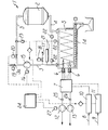
- the apparatus according to the invention comprises at least one container 2 for the scrap to be fed to the steelmaking furnace.
- the apparatus comprises a duct 3 for conveying gases at a preset temperature into the container 2, and a discharge duct 4 which collects the gases after they have passed through the scrap placed in the container 2 and the gaseous products released from the scrap owing to its heating performed by the gases.
- the duct 4 is connected to a reheating chamber 5, in which regenerative burners 6 are arranged in order to maintain a preset temperature inside the reheating chamber 2.
- the duct 3 can be connected to a combustion chamber or to a gas generation chamber, in which the gases to be conveyed to the container 2 are produced and which is separate from the reheating chamber 5; however, the duct 3 is preferably connected to said reheating chamber 5 so as to use, in order to preheat the scrap placed in the container 2, the same gases produced in the reheating chamber 5.
- the chamber for generating the gases to be used to preheat the scrap and the reheating chamber 5 are preferably constituted by a same chamber.
- the reheating chamber 5 is served by at least two regenerative burners 6, which are operated alternately so that while one is activated the other one aspirates gases from the reheating chamber 5. This produces, inside the reheating chamber 5, an intense turbulence which ensures excellent temperature uniformity and achieves maximum efficiency in heating the gases that pass through the reheating chamber 5.
- the regenerative burners 6, which are preferably constituted by high-efficiency burners, for example of the type disclosed in Italian patent no. 1,301,583 , are supplied by means of a fuel-air distribution unit 7 which is connected to a duct 8 for fuel supply and a duct 9 for pressurized air supply with corresponding controllable valves 10 and 11.
- the distribution unit 7 is further connected to an exhauster 12, which aspirates the gases from the reheating chamber 5 through the thermal accumulation material of the regenerative burners 6, and to an electric fan 13, which supplies comburent air to the regenerative burners through said thermal accumulation material in order to achieve preheating of the comburent air at the expense of the heat removed earlier from the gases extracted from the reheating chamber 5.
- an electromechanical scroll (14) for extracting and removing the dust released by the gases from the reheating chamber 5.
- the exhauster 15 is preferably actuated by means of a variable-speed motor 16 in order to vary, according to requirements and particularly according to the intended retention time of the gases inside the reheating chamber 5, the flow-rate of the gases along said circuit.
- an air intake duct 17 which is controlled by a controllable valve 18 in order to safeguard the integrity of the exhauster 15 by lowering the temperature of the gases if it is too high by supplying cold air through the duct 17.
- the duct 3 has, between the exhauster 15 and the container 2, a branch 3a which is controlled by a controllable valve, and downstream of said branch 3a the duct 3 is controlled by another controllable valve 20.
- a branch 3a which is controlled by a controllable valve
- another controllable valve 20 downstream of said branch 3a the duct 3 is controlled by another controllable valve 20.
- temperature sensing devices 22 are provided in the reheating chamber 5, along the duct 3 and along the duct 4.
- a device 23 for measuring the flow-rate of the gases that flow in the duct 3 is further arranged along the duct 3.
- the temperature sensors 22, the flow-rate measurement device 23 and the gas analyzer 21 are connected to a control and monitoring unit 24 of the electronic type which supervises the operation of the entire apparatus according to preset programs.
- Flow-rate measurement devices 25 and 26 are provided also along the gas extraction duct and along the comburent air supply duct, on which the exhauster 12 and the electric fan 13 used by the regenerative burners 6 are arranged; such measurement devices are also connected to the control and monitoring unit 24.
- the control and monitoring unit 24 is operatively connected to the motor 16 that drives the exhauster 15, to the motor 27 that drives the exhauster 12 and the electric fan 13, to the valves 10 and 11 that control the supply of fuel and comburent air to the burners 6, and to the controllable valves 18, 19 and 20.
- the control and monitoring unit 24 ensures the correct operation of the apparatus and particularly ensures that a preset temperature, preferably between 1100 and 1200 °C, is maintained inside the reheating chamber 5, ensures that the gases remain inside the reheating chamber 5 for a preset time, preferably 1.5 seconds or more, and ensures that the scrap placed in the container 2 is heated by gases which have a preset temperature, preferably between 1000 and 1100 °C.
- the apparatus 1 can also be installed in a region of the steelworks that is distant from the melting furnace, for example close to the scrap storage area.
- the hot gases which preferably arrive from the reheating chamber 5 itself, at a temperature which is preferably between 1000 and 1100 °C, flow through the scrap iron placed in the container 2 and heat it.
- the pollutants contained in the scrap such as plastics, rubbers, and oils, become gaseous in the form of chlorated aromatic hydrocarbons and dioxins, and are included in the gases that enter the reheating chamber 5 through the duct 4.
- the temperature of the fumes or gases that arrive from the scrap is increased to a temperature preferably between 1100 and 1200 °C and transit time of the gases through the reheating chamber 5 is at least equal to 1.5 seconds.
- the intense turbulence ensured by the regenerative burners 6 allows to obtain an excellent temperature uniformity inside the reheating chamber 5.
- Said high temperature and dwell time ensure breakdown of the pollutants removed from the scrap until at the output of the reheating chamber 5 said substances are reduced below the levels set by standards against atmospheric pollution.
- a fraction of the gases is extracted from the reheating chamber 5 through the regenerative burners 6 and transfers heat to the thermal accumulation material of said burners. This heat transfer achieves a rapid cooling of the gases which avoids recomposition of the pollutants. For this reason, the gases extracted from the reheating chamber 5 through the regenerative burners can be discharged into the atmosphere without further treatment.
- the combustible pollutants extracted from the scrap by means of the gases burn in the reheating chamber 5, thus cooperating with the burners 6 in raising the temperature inside said chamber, and also reducing the amount of fuel to be fed to the burners 6.
- the scrap which is preferably heated to a temperature of approximately 800-1000 °C and is freed of its pollutants, is then conveyed, preferably by means of the same container 2, into the electric furnace.
- the electric power required to achieve scrap melting is reduced considerably and the operation of the furnace is truly environment-friendly.
- the high temperature of the scrap introduced in the furnace achieves improved ionization of the electric arc generated by the electrodes, with consequent reductions in voltage fluctuations and flicker, with advantages also for the electric power supply network.
- Preheating of the scrap as performed with the method according to the invention eliminates the need to perform preheating in the furnace by means of additional burners, thus simplifying the structure, the operation and the maintenance of the furnace.
- noise emissions of the furnace during melting are also reduced, eliminating or in any case reducing the size of the investment required to provide structures aimed at reducing said noise emissions.
- Another advantage of the method according to the invention is that it does not require expensive gas scrubbing units or dust elimination units.
- the method according to the invention and the apparatus for carrying out it owing to the fact that they do not entail significant modifications to the conventional electric furnace, can be adopted both in new production units and in already-operating production units.
- the apparatus for carrying out the method according to the invention entails investments which are distinctly smaller than those required by innovative apparatuses that provide heating with continuous feeding of the scrap or in any case an in-line preheating which directly affects the operation of the electric furnace.
- the materials used, as well as the dimensions, may be any according to requirements and to the state of the art.
Landscapes
- Engineering & Computer Science (AREA)
- Chemical & Material Sciences (AREA)
- Mechanical Engineering (AREA)
- General Engineering & Computer Science (AREA)
- Materials Engineering (AREA)
- Manufacturing & Machinery (AREA)
- Metallurgy (AREA)
- Organic Chemistry (AREA)
- Environmental & Geological Engineering (AREA)
- Refinement Of Pig-Iron, Manufacture Of Cast Iron, And Steel Manufacture Other Than In Revolving Furnaces (AREA)
- Waste-Gas Treatment And Other Accessory Devices For Furnaces (AREA)
- Furnace Details (AREA)
- Vertical, Hearth, Or Arc Furnaces (AREA)
Claims (13)
- Verfahren zum Vorbereiten von Eisenschrott, der Elektroöfen zur Stahlherstellung zugeführt werden soll, umfassend die Schritte:Erzeugen von Heißgasen in einer Kammer zur Gaserzeugung, getrennt von dem Rauchgasableitungssystem des Stahlwerksofens,Fördern der Heißgase, so dass sie durch den dem Stahlwerksofen zuzuführenden Schrott strömen, um den Schrott vorzuwärmen,Fördern der zum Vorwärmen des Schrotts verwendeten Gase in eine Wiederaufheizungskammer, die auf einer gesteuerten Temperatur von im Wesentlichen zwischen 1100 und 1200°C durch mindestens zwei Regenerativbrenner gehalten wird, die beide für die Wiederaufheizungskammer vorgesehen sind und mittels einer Brennstoff-Luft-Verteilungseinheit abwechselnd arbeiten, so dass, während ein Brenner aktiviert ist, der andere Brenner Gase aus der Wiederaufheizungskammer absaugt,Halten der Gase in der genannten Wiederaufheizungskammer für eine vorgegebene Zeit von mindestens 1,5 Sekunden, ehe sie zurückgeführt werden, um den Schrott vorzuwärmen, oder in die Atmosphäre ausgestoßen werden, undExtrahieren und Beseitigen von Staub aus der Wiederaufheizungskammer.
- Verfahren nach Anspruch 1, dadurch gekennzeichnet, dass die Gaserzeugungskammer und die Wiederaufheizungskammer von ein und derselben Kammer gebildet sind.
- Verfahren nach einem oder mehr der vorhergehenden Ansprüche, dadurch gekennzeichnet, dass der Schrott mittels der Gase auf eine Temperatur vorgewärmt wird, die im Wesentlichen zwischen 1000 und 1100°C liegt.
- Verfahren nach einem oder mehr der vorhergehenden Ansprüche, dadurch gekennzeichnet, dass ein Bruchteil der in der Wiederaufheizungskammer enthaltenen Gase dazu verwendet wird, das Wärmespeichermaterial der Regenerativbrenner zu erwärmen, um die Brennluft vorzuwärmen, die den Regenerativbrennern zugeführt wird.
- Verfahren nach einem oder mehr der vorhergehenden Ansprüche, dadurch gekennzeichnet, dass der vorzuwärmende Schrott in mindestens einem Korb angeordnet ist, durch den die genannten Gase strömen.
- Vorrichtung zum Vorbereiten von Eisenschrott, der Elektroöfen zur Stahlherstellung zugeführt werden soll, wobei die Vorrichtung getrennt von der Vorrichtung zum Ableiten der Rauchgase des Stahlwerksofens angeordnet ist und eine Heißgas-Erzeugungskammer umfasst, die über einen Gasfördereinlasskanal (3) mit einem Behälter (2) für den dem Stahlwerksofen zuzuführenden Schrott verbunden ist, wobei der Behälter (2) wiederum über einen Gasauslasskanal (4) mit einer Wiederaufheizungskammer (5) verbunden ist, die mit mindestens zwei Brennern (6) versehen ist, um eine gesteuerte Temperatur in der Wiederaufheizungskammer (5) aufrechtzuerhalten, wobei die Brenner durch Regenerativbrenner (6) gebildet sind, die beide für die Wiederaufheizungskammer (5) vorgesehen sind und mittels einer Brennstoff-Luft-Verteilungseinheit (7) abwechselnd arbeiten, so dass, während ein Brenner aktiviert ist, der andere Brenner Gase aus der Wiederaufheizungskammer (5) absaugt, und wobei in der Wiederaufheizungskammer (5) ferner eine Förderschnecke (14) vorgesehen ist, um Staub aus der Wiederaufheizungskammer (5) zu extrahieren und zu beseitigen.
- Vorrichtung nach Anspruch 6, dadurch gekennzeichnet, dass die Gaserzeugungskammer und die Wiederaufheizungskammer von ein und derselben Kammer (5) gebildet sind.
- Vorrichtung nach den Ansprüchen 6 und 7, dadurch gekennzeichnet, dass Gasanalysemittel (21) entlang dem Gasförderkanal (3) angeordnet sind, am Ausgang der Wiederaufheizungskammer (5).
- Vorrichtung nach einem oder mehr der vorhergehenden Ansprüche 6-8, dadurch gekennzeichnet, dass sie Mittel (22) zum Erfassen der Temperatur in der Wiederaufheizungskammer (5) umfasst.
- Vorrichtung nach einem oder mehr der vorhergehenden Ansprüche 6-9, dadurch gekennzeichnet, dass sie Mittel (22) zum Erfassen der Temperatur der Gase entlang den Kanälen (3, 4) umfasst.
- Vorrichtung nach einem oder mehr der vorhergehenden Ansprüche 6-10, dadurch gekennzeichnet, dass sie Mittel (23) zum Erfassen der Durchflussrate der zu dem Schrottbehälter (2) geförderten Gase umfasst.
- Vorrichtung nach einem oder mehr der vorhergehenden Ansprüche 6-11, dadurch gekennzeichnet, dass sie Mittel (15) für die Zirkulation der Gase in dem Kreislauf umfasst, der aus der Wiederaufheizungskammer (5), dem Förderkanal (3), dem Schrottbehälter (2) und dem Auslasskanal (4) gebildet ist.
- Vorrichtung nach einem oder mehr der vorhergehenden Ansprüche 6-12, dadurch gekennzeichnet, dass sie eine elektronische Steuer- und Überwachungseinheit (24) umfasst, deren Eingang mit den Temperaturerfassungsmitteln (22), den Gasanalysemitteln (21) und den Durchflussratenerfassungsmitteln (23) verbunden ist, wobei die Steuer- und Überwachungseinheit (24) die Regenerativbrenner (6) und die Gaszirkulationsmittel (15) steuert, um eine vorgegebene Temperatur in der Wiederaufheizungskammer (5) aufrechtzuerhalten und den Rückhalt der Gase in der Wiederaufheizungskammer (5) für eine vorgegebene Zeit zu gewährleisten.
Priority Applications (3)
| Application Number | Priority Date | Filing Date | Title |
|---|---|---|---|
| AT01117639T ATE377741T1 (de) | 2001-07-24 | 2001-07-24 | Verfahren zur vorbereitung von im elektroofen zuzuführenden eisenschrott und vorrichtung zur durchführung des verfahrens |
| DE2001631269 DE60131269T2 (de) | 2001-07-24 | 2001-07-24 | Verfahren zur Vorbereitung von im Elektroofen zuzuführenden Eisenschrott und Vorrichtung zur Durchführung des Verfahrens |
| EP20010117639 EP1279914B1 (de) | 2001-07-24 | 2001-07-24 | Verfahren zur Vorbereitung von im Elektroofen zuzuführenden Eisenschrott und Vorrichtung zur Durchführung des Verfahrens |
Applications Claiming Priority (1)
| Application Number | Priority Date | Filing Date | Title |
|---|---|---|---|
| EP20010117639 EP1279914B1 (de) | 2001-07-24 | 2001-07-24 | Verfahren zur Vorbereitung von im Elektroofen zuzuführenden Eisenschrott und Vorrichtung zur Durchführung des Verfahrens |
Publications (2)
| Publication Number | Publication Date |
|---|---|
| EP1279914A1 EP1279914A1 (de) | 2003-01-29 |
| EP1279914B1 true EP1279914B1 (de) | 2007-11-07 |
Family
ID=8178096
Family Applications (1)
| Application Number | Title | Priority Date | Filing Date |
|---|---|---|---|
| EP20010117639 Expired - Lifetime EP1279914B1 (de) | 2001-07-24 | 2001-07-24 | Verfahren zur Vorbereitung von im Elektroofen zuzuführenden Eisenschrott und Vorrichtung zur Durchführung des Verfahrens |
Country Status (3)
| Country | Link |
|---|---|
| EP (1) | EP1279914B1 (de) |
| AT (1) | ATE377741T1 (de) |
| DE (1) | DE60131269T2 (de) |
Families Citing this family (2)
| Publication number | Priority date | Publication date | Assignee | Title |
|---|---|---|---|---|
| FI20061123A7 (fi) * | 2006-12-15 | 2008-06-16 | Outotec Oyj | Menetelmä sulatusuuniin syötettävän materiaalin esikäsittelemiseksi ja etukuumennusjärjestelmä |
| EP2792984B8 (de) | 2013-04-17 | 2021-04-21 | Gf-Elti S.R.L. | Verfahren zur Herstellung und Zuführung von Metallschrott an einen elektrischen Schmelzofen zur Herstellung von Stahl |
Family Cites Families (4)
| Publication number | Priority date | Publication date | Assignee | Title |
|---|---|---|---|---|
| SE440145B (sv) * | 1981-12-01 | 1985-07-15 | Asea Ab | Skrotforvermare |
| TW221462B (de) * | 1991-06-28 | 1994-03-01 | Stein Atkinson Strody Ltd | |
| JPH09133476A (ja) * | 1995-11-02 | 1997-05-20 | Ishikawajima Harima Heavy Ind Co Ltd | スクラップ予熱設備 |
| JP3719616B2 (ja) * | 1995-12-28 | 2005-11-24 | 日本ファーネス工業株式会社 | 気流炉 |
-
2001
- 2001-07-24 AT AT01117639T patent/ATE377741T1/de not_active IP Right Cessation
- 2001-07-24 EP EP20010117639 patent/EP1279914B1/de not_active Expired - Lifetime
- 2001-07-24 DE DE2001631269 patent/DE60131269T2/de not_active Expired - Lifetime
Also Published As
| Publication number | Publication date |
|---|---|
| ATE377741T1 (de) | 2007-11-15 |
| DE60131269T2 (de) | 2008-03-06 |
| EP1279914A1 (de) | 2003-01-29 |
| DE60131269D1 (de) | 2007-12-20 |
Similar Documents
| Publication | Publication Date | Title |
|---|---|---|
| RU2086869C1 (ru) | Способ непрерывного предварительного нагрева шихтовых материалов для сталеплавильной печи и установка для его осуществления | |
| JP2791985B2 (ja) | 廃棄物熱処理設備並びにその設備の運転方法 | |
| CN101120221B (zh) | 用于将电弧炉排出的气体预热废钢的设备和方法 | |
| CN111321272A (zh) | 一种连续预热废钢的炼钢装置及工艺 | |
| CA1134139A (en) | Energy efficient heat-treating furnace system | |
| US3837794A (en) | Billet heating | |
| JP2009287863A (ja) | 加熱処理装置 | |
| EP1279914B1 (de) | Verfahren zur Vorbereitung von im Elektroofen zuzuführenden Eisenschrott und Vorrichtung zur Durchführung des Verfahrens | |
| US4812117A (en) | Method and device for pre-heating waste metal for furnaces | |
| JP2005226157A (ja) | 連続焼鈍炉の炉温制御方法および炉温制御装置 | |
| US5000425A (en) | Method of preheating scrap | |
| KR101567866B1 (ko) | 전기 아크로 및 전기 아크로의 스크랩 예열 방법 | |
| JP2009155691A (ja) | 直火型ローラーハース式連続熱処理炉 | |
| CN109797268B (zh) | 利用电弧炉消纳废弃物的炼钢装置和方法 | |
| CN102778133A (zh) | 台车式燃气热处理炉进风系统 | |
| WO2004038315A1 (ja) | 連続式焼成炉 | |
| JP6203998B2 (ja) | 加熱装置 | |
| JP2002301459A (ja) | 廃棄物処理方法及び処理装置 | |
| KR20210072917A (ko) | 가열로 배가스 재순환 장치 및 방법 | |
| CN218155450U (zh) | 一种宽体辊道窑 | |
| JPS62290825A (ja) | 連続加熱炉における排ガス利用方法 | |
| KR101558440B1 (ko) | 배가스 분기방식을 이용한 스크랩 예열장치, 예열방법, 그 예열장치를 갖는 전기 아크로 및 그 전기 아크로의 작동방법 | |
| CN202770245U (zh) | 具有辅助燃烧功能的炭素焙烧炉控制系统 | |
| KR101462465B1 (ko) | 배가스 부분 재순환 스크랩 예열장치, 예열방법, 그 예열장치를 갖는 전기 아크로 및 그 전기 아크로의 작동방법 | |
| RU2575890C2 (ru) | Нагревательное устройство |
Legal Events
| Date | Code | Title | Description |
|---|---|---|---|
| PUAI | Public reference made under article 153(3) epc to a published international application that has entered the european phase |
Free format text: ORIGINAL CODE: 0009012 |
|
| AK | Designated contracting states |
Designated state(s): AT BE CH CY DE DK ES FI FR GB GR IE IT LI LU MC NL PT SE TR |
|
| AX | Request for extension of the european patent |
Extension state: AL LT LV MK RO SI |
|
| 17P | Request for examination filed |
Effective date: 20030701 |
|
| AKX | Designation fees paid |
Designated state(s): AT BE CH CY DE DK ES FI FR GB GR IE IT LI LU MC NL PT SE TR |
|
| 17Q | First examination report despatched |
Effective date: 20050615 |
|
| GRAP | Despatch of communication of intention to grant a patent |
Free format text: ORIGINAL CODE: EPIDOSNIGR1 |
|
| GRAS | Grant fee paid |
Free format text: ORIGINAL CODE: EPIDOSNIGR3 |
|
| GRAA | (expected) grant |
Free format text: ORIGINAL CODE: 0009210 |
|
| AK | Designated contracting states |
Kind code of ref document: B1 Designated state(s): AT BE CH CY DE DK ES FI FR GB GR IE IT LI LU MC NL PT SE TR |
|
| REG | Reference to a national code |
Ref country code: GB Ref legal event code: FG4D |
|
| REG | Reference to a national code |
Ref country code: IE Ref legal event code: FG4D |
|
| REG | Reference to a national code |
Ref country code: CH Ref legal event code: EP |
|
| REF | Corresponds to: |
Ref document number: 60131269 Country of ref document: DE Date of ref document: 20071220 Kind code of ref document: P |
|
| REG | Reference to a national code |
Ref country code: CH Ref legal event code: NV Representative=s name: E. BLUM & CO. AG PATENT- UND MARKENANWAELTE VSP |
|
| PG25 | Lapsed in a contracting state [announced via postgrant information from national office to epo] |
Ref country code: ES Free format text: LAPSE BECAUSE OF FAILURE TO SUBMIT A TRANSLATION OF THE DESCRIPTION OR TO PAY THE FEE WITHIN THE PRESCRIBED TIME-LIMIT Effective date: 20080218 Ref country code: SE Free format text: LAPSE BECAUSE OF FAILURE TO SUBMIT A TRANSLATION OF THE DESCRIPTION OR TO PAY THE FEE WITHIN THE PRESCRIBED TIME-LIMIT Effective date: 20080207 Ref country code: NL Free format text: LAPSE BECAUSE OF FAILURE TO SUBMIT A TRANSLATION OF THE DESCRIPTION OR TO PAY THE FEE WITHIN THE PRESCRIBED TIME-LIMIT Effective date: 20071107 |
|
| NLV1 | Nl: lapsed or annulled due to failure to fulfill the requirements of art. 29p and 29m of the patents act | ||
| PG25 | Lapsed in a contracting state [announced via postgrant information from national office to epo] |
Ref country code: AT Free format text: LAPSE BECAUSE OF FAILURE TO SUBMIT A TRANSLATION OF THE DESCRIPTION OR TO PAY THE FEE WITHIN THE PRESCRIBED TIME-LIMIT Effective date: 20071107 |
|
| ET | Fr: translation filed | ||
| PG25 | Lapsed in a contracting state [announced via postgrant information from national office to epo] |
Ref country code: DK Free format text: LAPSE BECAUSE OF FAILURE TO SUBMIT A TRANSLATION OF THE DESCRIPTION OR TO PAY THE FEE WITHIN THE PRESCRIBED TIME-LIMIT Effective date: 20071107 |
|
| PG25 | Lapsed in a contracting state [announced via postgrant information from national office to epo] |
Ref country code: BE Free format text: LAPSE BECAUSE OF FAILURE TO SUBMIT A TRANSLATION OF THE DESCRIPTION OR TO PAY THE FEE WITHIN THE PRESCRIBED TIME-LIMIT Effective date: 20071107 |
|
| PLBE | No opposition filed within time limit |
Free format text: ORIGINAL CODE: 0009261 |
|
| STAA | Information on the status of an ep patent application or granted ep patent |
Free format text: STATUS: NO OPPOSITION FILED WITHIN TIME LIMIT |
|
| PG25 | Lapsed in a contracting state [announced via postgrant information from national office to epo] |
Ref country code: PT Free format text: LAPSE BECAUSE OF FAILURE TO SUBMIT A TRANSLATION OF THE DESCRIPTION OR TO PAY THE FEE WITHIN THE PRESCRIBED TIME-LIMIT Effective date: 20080407 |
|
| 26N | No opposition filed |
Effective date: 20080808 |
|
| PG25 | Lapsed in a contracting state [announced via postgrant information from national office to epo] |
Ref country code: GR Free format text: LAPSE BECAUSE OF FAILURE TO SUBMIT A TRANSLATION OF THE DESCRIPTION OR TO PAY THE FEE WITHIN THE PRESCRIBED TIME-LIMIT Effective date: 20080208 |
|
| PG25 | Lapsed in a contracting state [announced via postgrant information from national office to epo] |
Ref country code: FI Free format text: LAPSE BECAUSE OF FAILURE TO SUBMIT A TRANSLATION OF THE DESCRIPTION OR TO PAY THE FEE WITHIN THE PRESCRIBED TIME-LIMIT Effective date: 20071107 |
|
| PG25 | Lapsed in a contracting state [announced via postgrant information from national office to epo] |
Ref country code: MC Free format text: LAPSE BECAUSE OF NON-PAYMENT OF DUE FEES Effective date: 20080731 |
|
| PG25 | Lapsed in a contracting state [announced via postgrant information from national office to epo] |
Ref country code: CY Free format text: LAPSE BECAUSE OF FAILURE TO SUBMIT A TRANSLATION OF THE DESCRIPTION OR TO PAY THE FEE WITHIN THE PRESCRIBED TIME-LIMIT Effective date: 20071107 Ref country code: IE Free format text: LAPSE BECAUSE OF NON-PAYMENT OF DUE FEES Effective date: 20080724 |
|
| PG25 | Lapsed in a contracting state [announced via postgrant information from national office to epo] |
Ref country code: LU Free format text: LAPSE BECAUSE OF NON-PAYMENT OF DUE FEES Effective date: 20080724 |
|
| PG25 | Lapsed in a contracting state [announced via postgrant information from national office to epo] |
Ref country code: TR Free format text: LAPSE BECAUSE OF FAILURE TO SUBMIT A TRANSLATION OF THE DESCRIPTION OR TO PAY THE FEE WITHIN THE PRESCRIBED TIME-LIMIT Effective date: 20071107 |
|
| REG | Reference to a national code |
Ref country code: DE Ref legal event code: R082 Ref document number: 60131269 Country of ref document: DE Representative=s name: SCHAUMBURG & PARTNER PATENTANWAELTE GBR, DE Ref country code: DE Ref legal event code: R082 Ref document number: 60131269 Country of ref document: DE Representative=s name: SCHAUMBURG UND PARTNER PATENTANWAELTE MBB, DE |
|
| REG | Reference to a national code |
Ref country code: FR Ref legal event code: PLFP Year of fee payment: 16 |
|
| REG | Reference to a national code |
Ref country code: FR Ref legal event code: PLFP Year of fee payment: 17 |
|
| REG | Reference to a national code |
Ref country code: FR Ref legal event code: PLFP Year of fee payment: 18 |
|
| PGFP | Annual fee paid to national office [announced via postgrant information from national office to epo] |
Ref country code: CH Payment date: 20200626 Year of fee payment: 20 |
|
| PGFP | Annual fee paid to national office [announced via postgrant information from national office to epo] |
Ref country code: DE Payment date: 20200728 Year of fee payment: 20 Ref country code: GB Payment date: 20200720 Year of fee payment: 20 Ref country code: FR Payment date: 20200728 Year of fee payment: 20 |
|
| PGFP | Annual fee paid to national office [announced via postgrant information from national office to epo] |
Ref country code: IT Payment date: 20200701 Year of fee payment: 20 |
|
| REG | Reference to a national code |
Ref country code: DE Ref legal event code: R071 Ref document number: 60131269 Country of ref document: DE |
|
| REG | Reference to a national code |
Ref country code: CH Ref legal event code: PL |
|
| REG | Reference to a national code |
Ref country code: GB Ref legal event code: PE20 Expiry date: 20210723 |
|
| PG25 | Lapsed in a contracting state [announced via postgrant information from national office to epo] |
Ref country code: GB Free format text: LAPSE BECAUSE OF EXPIRATION OF PROTECTION Effective date: 20210723 |