EP1279895A1 - Tête de combustion d'un brûleur comprenant une zone de pré-vaporisation du combustible liquide - Google Patents
Tête de combustion d'un brûleur comprenant une zone de pré-vaporisation du combustible liquide Download PDFInfo
- Publication number
- EP1279895A1 EP1279895A1 EP01420170A EP01420170A EP1279895A1 EP 1279895 A1 EP1279895 A1 EP 1279895A1 EP 01420170 A EP01420170 A EP 01420170A EP 01420170 A EP01420170 A EP 01420170A EP 1279895 A1 EP1279895 A1 EP 1279895A1
- Authority
- EP
- European Patent Office
- Prior art keywords
- liquid fuel
- injecting
- front compartment
- combustion head
- compartment
- Prior art date
- Legal status (The legal status is an assumption and is not a legal conclusion. Google has not performed a legal analysis and makes no representation as to the accuracy of the status listed.)
- Withdrawn
Links
Images
Classifications
-
- F—MECHANICAL ENGINEERING; LIGHTING; HEATING; WEAPONS; BLASTING
- F23—COMBUSTION APPARATUS; COMBUSTION PROCESSES
- F23D—BURNERS
- F23D11/00—Burners using a direct spraying action of liquid droplets or vaporised liquid into the combustion space
- F23D11/36—Details, e.g. burner cooling means, noise reduction means
- F23D11/44—Preheating devices; Vaporising devices
- F23D11/441—Vaporising devices incorporated with burners
- F23D11/443—Vaporising devices incorporated with burners heated by the main burner flame
- F23D11/445—Vaporising devices incorporated with burners heated by the main burner flame the flame and the vaporiser not coming into direct contact
-
- F—MECHANICAL ENGINEERING; LIGHTING; HEATING; WEAPONS; BLASTING
- F23—COMBUSTION APPARATUS; COMBUSTION PROCESSES
- F23D—BURNERS
- F23D11/00—Burners using a direct spraying action of liquid droplets or vaporised liquid into the combustion space
- F23D11/36—Details, e.g. burner cooling means, noise reduction means
- F23D11/40—Mixing tubes or chambers; Burner heads
- F23D11/404—Flame tubes
-
- F—MECHANICAL ENGINEERING; LIGHTING; HEATING; WEAPONS; BLASTING
- F23—COMBUSTION APPARATUS; COMBUSTION PROCESSES
- F23C—METHODS OR APPARATUS FOR COMBUSTION USING FLUID FUEL OR SOLID FUEL SUSPENDED IN A CARRIER GAS OR AIR
- F23C2202/00—Fluegas recirculation
- F23C2202/10—Premixing fluegas with fuel and combustion air
-
- F—MECHANICAL ENGINEERING; LIGHTING; HEATING; WEAPONS; BLASTING
- F23—COMBUSTION APPARATUS; COMBUSTION PROCESSES
- F23C—METHODS OR APPARATUS FOR COMBUSTION USING FLUID FUEL OR SOLID FUEL SUSPENDED IN A CARRIER GAS OR AIR
- F23C2900/00—Special features of, or arrangements for combustion apparatus using fluid fuels or solid fuels suspended in air; Combustion processes therefor
- F23C2900/09002—Specific devices inducing or forcing flue gas recirculation
Definitions
- the invention relates to a combustion head of a burner with liquid fuel and gaseous oxidizer, and more particularly to a combustion head comprising a front compartment and a rear compartment separated by a separation disc and means for injecting respectively liquid fuel and gaseous oxidant from the rear compartment in a mixing zone of the front compartment.
- a combustion head of this type is known from documents DE-A-4,209,220 and DE-A-3,430,010.
- the means for injecting the liquid fuel comprises a nozzle arranged in the rear compartment and opening into the front compartment through a central opening of the separation disc.
- the means for injecting the gaseous oxidant comprises openings formed in the separation disc and disposed peripherally relative to the central opening.
- the liquid fuel and the gaseous oxidizer are injected into a mixing zone of the front compartment delimited by a mixing tube.
- the latter is provided with openings to allow burnt gases resulting from the combustion of the fuel and of the oxidant to recirculate in the mixing zone. The recirculation of the burnt gases makes it possible to reduce the quantity of polluting emission from the combustion head.
- the recirculation openings formed in the mixing tube are arranged downstream relative to the injection openings of the gaseous oxidant.
- the means for injecting the liquid fuel and the gaseous oxidizer both open into the front compartment instead of the combustion head separation disc.
- a combustion head of the type recalled above is also known from document EP-A-386 732.
- the means for injecting the gaseous oxidizer comprises tubes fixed to the separation disc, open on the one hand on the rear compartment and opening out from elsewhere in the front compartment upstream from the liquid fuel injection nozzle.
- the tubes are separated from each other to form recirculation paths of the burnt gases around the nozzle for injecting the liquid fuel.
- the liquid fuel is gradually vaporized as it is mixed with the gaseous oxidizer and with the burnt gases recirculating in the mixing zone.
- the presence in this zone of the liquid fuel reduces the homogeneity of the mixture with the gaseous oxidizer and affects the combustion efficiency of the combustion head as well as the proportion of polluting emissions.
- a combustion head of a liquid fuel and gaseous oxidant burner comprising a front compartment and a rear compartment separated by a separating disc and means for injecting respectively a liquid fuel and a gaseous oxidant from the rear compartment into an area mixing the front compartment, the means for injecting the gaseous oxidant opening into the front compartment downstream relative to the means for injecting the liquid fuel is known from document WO-A-88 03 249.
- the means for injecting the gaseous oxidant comprises a double annular shell fixed to the separation disc, open on the one hand on the rear compartment and opening on the other hand on the front compartment.
- the outer wall of the double annular shell is closed to the recirculation of the burnt gases to promote heat exchange with the gaseous oxidant and thus preheat the latter before it is mixed with the liquid fuel in the mixing zone.
- This arrangement again leads to vaporization of the liquid fuel in the mixing zone itself and consequently to incomplete homogeneity in the gas phase of the mixture.
- One of the aims of the invention is to design a combustion head of a burner with liquid fuel and with gaseous oxidizer making it possible to increase the homogeneity in the gas phase of the fuel and of the oxidant in order to increase the combustion efficiency of the head and to reduce polluting emissions.
- the subject of the invention is a combustion head of a burner with liquid fuel and with gaseous oxidizer, comprising a front compartment and a rear compartment separated by a separation disc and means for injecting respectively a liquid fuel and oxidant gas from the rear compartment in a mixing zone of the front compartment, passages being provided in the means for injecting the gaseous oxidizer to allow burnt gases resulting from the combustion of the fuel and the oxidant to recirculate in the mixing zone, characterized in that the means for injecting the gaseous oxidant opens into the front compartment downstream relative to the means of injecting the liquid fuel to create upstream of the zone of mixing with the gaseous oxidizer a zone of vaporization by the burnt gases recirculating the injected liquid fuel.
- the vaporization of the liquid fuel upstream of the mixing zone makes it possible to increase the gas homogeneity of the mixture. This results in an increase in combustion efficiency and a decrease in polluting emissions.
- the means for injecting the gaseous oxidizer comprises a flame stabilization member fixed at its mouth in the front compartment of the combustion head.
- the stabilization member fixed to the mouth of the means for injecting the gaseous oxidant into the front compartment makes it possible to stabilize the flame with respect to variations in the rate of injection of the liquid fuel or of the gaseous oxidant.
- the stabilization of the flame results in a reduction in pressure variations in the front compartment of the combustion head and consequently in a reduction in the noise level of the combustion head in operation.
- the recirculation of the burnt gases favorable to the reduction of polluting emissions, generally results in an increase in pressure variations in the front compartment and as a result of the operating noise level.
- the advantageous form of the invention which has just been described is all the more advantageous since it makes it possible both to reduce the operating noise level and the polluting emissions from the combustion head.
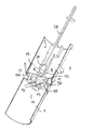
- FIG. 1 shows a mixed view in section and in perspective of a combustion head according to the invention.
- a combustion head of a liquid fuel and gaseous oxidizer burner comprises, FIG. 1, a front compartment 1 and a rear compartment 3 separated by a separation disc 5.
- the two front and rear compartments are formed in a cylindrical tube.
- Means 7 for injecting a liquid fuel for example a fuel
- Means 7 for injecting a liquid fuel comprises an injection nozzle 7A supplied by a nozzle line 7B.
- the injection nozzle 7A and the nozzle line 7B are arranged in the axis of the rear compartment 3 by means of support arms not shown.
- the liquid fuel is injected from the rear compartment 3 into the front compartment 1 through a central opening 8 of the separation disc 5.
- the separation disc 5 is carried by the injection means 7 by fixing arms 6.
- the liquid fuel is injected into the front compartment 1 in the form of droplets by an atomizer not shown, arranged downstream of the injection nozzle 7A.
- a means 9 for injecting a gaseous oxidizer for example air, comprises tubes 9A fixed to the separation disc 5, open on the one hand on the rear compartment 3 and opening on the other hand in the front compartment 1.
- the gaseous oxidizer is injected from the rear compartment 3 into the front compartment 1 for example by a fan (not shown), disposed in the rear compartment 3.
- the gaseous oxidizer and the liquid fuel are injected into the front compartment 1, downstream from the disc separation 5, in a mixing zone 11 where a combustion flame arises.
- the tubes 9A are separated from each other on the separation disc 5 to form recirculation passages in the mixing zone 11 of the burnt gases resulting from the combustion of the fuel and of the oxidant.
- the tubes 9A of the injection means 9 of the gaseous oxidizer open into the front compartment 1 downstream relative to the injection nozzle 7A of the liquid fuel.
- the mouth 9B of these tubes 9A thus creates upstream of the mixing zone 11 a zone 12 where the burnt gases recirculating through the passages 13 formed between the tubes 9A provide the thermal energy necessary for the vaporization of the droplets of the liquid fuel injected by the injection nozzle 7A.
- the vaporization upstream of the mixing zone 11, of the liquid fuel injected by the recirculating gases makes it possible to homogenize in the gas phase the mixture of the fuel and of the oxidizer.
- the tubes 9A of the injection means 9 are replaced by a double annular shell fixed to the separation disc 5, open on the one hand on the rear compartment 3 and opening out to on the other hand on the front compartment 1 downstream relative to the injection nozzle 7A and provided with through channels for the recirculation of the burnt gases in the vaporization zone 12.
- the means for injecting the gaseous oxidant 9 comprises a flame stabilization member 15 fixed at its mouth in the front compartment 1.
- the stabilization is an annular plate 15 fixed to the mouth 9B of the tubes 9A of the injection means 9 of the gaseous oxidizer and pierced with openings 15A allowing the injection of the gaseous oxidizer.
- this advantageous form of the invention is all the more advantageous since it makes it possible both to reduce the operating noise level and the polluting emissions from the combustion head.
- the burnt gases can not only recirculate internally in the front compartment 1 of the combustion head but also externally by recirculation openings 17 formed in the front compartment 1 downstream of the disc of separation 5.
- the external recirculation openings 17 are provided upstream of the mouth 9B of the tubes 9A of the injection means 9 of the gaseous oxidizer to allow the gases recirculating externally to the front compartment 1 to penetrate in the vaporization zone 12.
- the injection means 7 and 9 respectively of the liquid fuel and of the gaseous oxidizer form with the separation disc 5 a movable assembly in sliding contiguous with respect to the rear compartment 3 for more or less sealing off the external recirculation openings 17 of the burnt gases.
- the contiguous sliding is ensured, in the example of FIG. 1, by a ring 19 comprising annular grooves for accommodating elastic segments or O-rings 21.
Landscapes
- Engineering & Computer Science (AREA)
- Chemical & Material Sciences (AREA)
- Combustion & Propulsion (AREA)
- Mechanical Engineering (AREA)
- General Engineering & Computer Science (AREA)
Abstract
Description
- L'invention se rapporte à une tête de combustion d'un brûleur à combustible liquide et à comburant gazeux, et plus particulièrement à une tête de combustion comprenant un compartiment avant et un compartiment arrière séparés par un disque de séparation et des moyens pour injecter respectivement un combustible liquide et un comburant gazeux depuis le compartiment arrière dans une zone de mélange du compartiment avant.
- Une tête de combustion de ce type est connue des documents DE-A-4 209 220 et DE-A-3 430 010. Le moyen pour injecter le combustible liquide comprend une buse disposée dans le compartiment arrière et débouchant dans le compartiment avant par une ouverture centrale du disque de séparation. Le moyen pour injecter le comburant gazeux comprend des ouvertures formées dans le disque de séparation et disposées de façon périphérique par rapport à l'ouverture centrale. Le combustible liquide et le comburant gazeux sont injectés dans une zone de mélange du compartiment avant délimitée par un tube de mélange. Ce dernier est muni d'ouvertures pour permettre à des gaz brûlés résultant de la combustion du combustible et du comburant de recirculer dans la zone de mélange. La recirculation des gaz brûlés permet de diminuer la quantité d'émission polluante de la tête de combustion. Il convient de noter que dans ces documents, les ouvertures de recirculation ménagées dans le tube de mélange sont disposées en aval par rapport aux ouvertures d'injection du comburant gazeux. De surcroît, les moyens d'injection du combustible liquide et du comburant gazeux débouchent l'un et l'autre dans le compartiment avant au lieu même du disque de séparation de la tête de combustion.
- Une tête de combustion du type rappelé précédemment est également connue du document EP-A-386 732. Le moyen d'injection du comburant gazeux comprend des tubes fixés au disque de séparation, ouverts d'une part sur le compartiment arrière et débouchant d'autre part dans le compartiment avant en amont par rapport à la buse d'injection du combustible liquide. De surcroît, les tubes sont séparés les uns des autres pour former des voies de recirculation des gaz brûlés autour de la buse d'injection du combustible liquide. Par la disposition relative de la buse d'injection du combustible liquide et des tubes d'injection du comburant gazeux, ce dernier pénètre dans la zone de mélange et est réchauffé par la recirculation des gaz brûlés en amont de l'injection du combustible liquide.
- Dans ces têtes de combustion connues, le combustible liquide est progressivement vaporisé au fur et mesure de son mélange avec le comburant gazeux et avec les gaz brûlés recirculant dans la zone de mélange. La présence dans cette zone du combustible liquide, par exemple sous forme de gouttelettes, diminue l'homogénéité du mélange avec le comburant gazeux et affecte le rendement de combustion de la tête de combustion ainsi que la proportion des émissions polluantes.
- Une tête de combustion d'un brûleur à combustible liquide et à comburant gazeux, comprenant un compartiment avant et un compartiment arrière séparés par un disque de séparation et des moyens pour injecter respectivement un combustible liquide et un comburant gazeux depuis le compartiment arrière dans une zone de mélange du compartiment avant, le moyen d'injection du comburant gazeux débouchant dans le compartiment avant en aval par rapport au moyen d'injection du combustible liquide est connue du document WO-A-88 03 249. Le moyen pour injecter le comburant gazeux comprend une double coque annulaire fixée au disque de séparation, ouverte d'une part sur le compartiment arrière et débouchant d'autre part sur le compartiment avant. Toutefois, la paroi extérieure de la double coque annulaire est fermée à la recirculation des gaz brûlés pour favoriser un échange thermique avec le comburant gazeux et ainsi préchauffer ce dernier avant son mélange avec le combustible liquide dans la zone de mélange. Cet agencement conduit là encore à une vaporisation du combustible liquide dans la zone même de mélange et par voie de conséquence à une homogénéité incomplète en phase gazeuse du mélange.
- L'un des buts de l'invention est de concevoir une tête de combustion d'un brûleur à combustible liquide et à comburant gazeux permettant d'augmenter l'homogénéité en phase gazeuse du combustible et du comburant pour augmenter le rendement de combustion de la tête et pour diminuer les émissions polluantes.
- A cet effet, l'invention a pour objet une tête de combustion d'un brûleur à combustible liquide et à comburant gazeux, comprenant un compartiment avant et un compartiment arrière séparés par un disque de séparation et des moyens pour injecter respectivement un combustible liquide et un comburant gazeux depuis le compartiment arrière dans une zone de mélange du compartiment avant, des passages étant ménagés dans le moyen d'injection du comburant gazeux pour permettre à des gaz brûlés résultant de la combustion du combustible et du comburant de recirculer dans la zone de mélange, caractérisée en ce que le moyen d'injection du comburant gazeux débouche dans le compartiment avant en aval par rapport au moyen d'injection du combustible liquide pour créer en amont de la zone de mélange avec le comburant gazeux une zone de vaporisation par les gaz brûlés recirculant du combustible liquide injecté.
- La vaporisation du combustible liquide en amont de la zone de mélange permet d'augmenter l'homogénéité gazeuse du mélange. D'où il résulte une augmentation du rendement de combustion et une diminution des émissions polluantes.
- Selon une conception avantageuse de l'invention, le moyen d'injection du comburant gazeux comprend un organe de stabilisation de flamme fixé à son embouchure dans le compartiment avant de la tête de combustion.
- L'organe de stabilisation fixé à l'embouchure du moyen d'injection du comburant gazeux dans le compartiment avant permet de stabiliser la flamme par rapport à des variations de débit d'injection du combustible liquide ou du comburant gazeux. La stabilisation de la flamme résulte en une diminution des variations de pression dans le compartiment avant de la tête de combustion et par voie de conséquence en une diminution du niveau sonore de la tête de combustion en fonctionnement. Il convient de noter que la recirculation des gaz brûlés, favorable à la réduction des émissions polluantes, entraîne généralement une augmentation des variations de pression dans le compartiment avant et par suite du niveau sonore de fonctionnement. La forme avantageuse de l'invention qui vient d'être décrite présente d'autant plus d'intérêt qu'elle permet à la fois de réduire le niveau sonore de fonctionnement et les émissions polluantes de la tête de combustion.
- D'autres avantages de l'invention apparaîtront à la lecture de la description d'un mode de réalisation illustré par la figure 1 unique montrant une vue mixte en coupe et en perspective d'une tête de combustion selon l'invention.
- Une tête de combustion d'un brûleur à combustible liquide et à comburant gazeux comprend, figure 1, un compartiment avant 1 et un compartiment arrière 3 séparés par un disque de séparation 5. Dans l'exemple de la figure 1, les deux compartiments avant et arrière sont formés dans un tube cylindrique.
- Un moyen 7 pour injecter un combustible liquide, par exemple un fuel, comprend une buse d'injection 7A alimentée par une ligne de gicleur 7B. La buse d'injection 7A et la ligne de gicleur 7B sont disposées dans l'axe du compartiment arrière 3 au moyen de bras de support non représentés. Le combustible liquide est injecté du compartiment arrière 3 dans le compartiment avant 1 à travers une ouverture centrale 8 du disque de séparation 5. Dans l'exemple de la figure 1, le disque de séparation 5 est porté par le moyen d'injection 7 par des bras de fixation 6. Le combustible liquide est injecté dans le compartiment avant 1 sous forme de gouttelettes par un atomiseur non représenté, disposé en aval de la buse d'injection 7A.
- Un moyen 9 pour injecter un comburant gazeux, par exemple de l'air, comprend des tubes 9A fixés au disque de séparation 5, ouverts d'une part sur le compartiment arrière 3 et débouchant d'autre part dans le compartiment avant 1. Le comburant gazeux est injecté depuis le compartiment arrière 3 dans le compartiment avant 1 par exemple par un ventilateur non représenté, disposé dans le compartiment arrière 3. Le comburant gazeux et le combustible liquide sont injectés dans le compartiment avant 1, en aval par rapport au disque de séparation 5, dans une zone de mélange 11 où une flamme de combustion prend naissance. Les tubes 9A sont séparés les uns des autres sur le disque de séparation 5 pour former des passages de recirculation dans la zone de mélange 11 des gaz brûlés résultant de la combustion du combustible et du comburant.
- Selon l'invention, les tubes 9A du moyen d'injection 9 du comburant gazeux débouchent dans le compartiment avant 1 en aval par rapport à la buse d'injection 7A du combustible liquide. L'embouchure 9B de ces tubes 9A crée ainsi en amont de la zone de mélange 11 une zone 12 où les gaz brûlés recirculant à travers les passages 13 ménagés entre les tubes 9A fournissent l'énergie thermique nécessaire à la vaporisation des gouttelettes du combustible liquide injecté par la buse d'injection 7A. Comme indiqué précédemment, la vaporisation en amont de la zone de mélange 11, du combustible liquide injecté par les gaz recirculant permet d'homogénéiser en phase gazeuse le mélange du combustible et du comburant.
- Selon un autre mode d'exécution de l'invention non représenté, les tubes 9A du moyen d'injection 9 sont remplacés par une double coque annulaire fixée au disque de séparation 5, ouverte d'une part sur le compartiment arrière 3 et débouchant d'autre part sur le compartiment avant 1 en aval par rapport à la buse d'injection 7A et pourvue de canaux traversant pour la recirculation des gaz brûlés dans la zone de vaporisation 12.
- Selon une conception avantageuse de l'invention, le moyen d'injection du comburant gazeux 9 comprend un organe de stabilisation de flamme 15 fixé à son embouchure dans le compartiment avant 1. Dans l'exemple illustré par la figure 1, l'organe de stabilisation est une plaque annulaire 15 fixée à l'embouchure 9B des tubes 9A du moyen d'injection 9 du comburant gazeux et percée d'ouvertures 15A permettant l'injection du comburant gazeux.
- Comme indiqué précédemment, cette forme avantageuse de l'invention présente d'autant plus d'intérêt qu'elle permet à la fois de réduire le niveau sonore de fonctionnement et les émissions polluantes de la tête de combustion.
- Dans l'exemple de la figure 1, les gaz brûlés peuvent non seulement recirculer de façon interne au compartiment avant 1 de la tête de combustion mais également de façon externe par des ouvertures de recirculation 17 formées dans le compartiment avant 1 en aval du disque de séparation 5. D'une façon avantageuse, les ouvertures de recirculation externe 17 sont ménagées en amont de l'embouchure 9B des tubes 9A du moyen d'injection 9 du comburant gazeux pour permettre aux gaz recirculant de façon externe au compartiment avant 1 de pénétrer dans la zone de vaporisation 12. De préférence, les moyens d'injection 7 et 9 respectivement du combustible liquide et du comburant gazeux forment avec le disque de séparation 5 un équipage mobile en coulissement jointif par rapport au compartiment arrière 3 pour plus ou moins obturer les ouvertures de recirculation externe 17 des gaz brûlés. Le coulissement jointif est assuré, dans l'exemple de la figure 1, par une bague 19 comprenant des rainures annulaires pour loger des segments élastiques ou des joints toriques 21.
Claims (6)
- Tête de combustion d'un brûleur à combustible liquide et à comburant gazeux, comprenant un compartiment avant (1) et un compartiment arrière (3) séparés par un disque de séparation (5) et des moyens (7,9) pour injecter respectivement un combustible liquide et un comburant gazeux depuis le compartiment arrière dans une zone de mélange (11) du compartiment avant, des passages (13) étant ménagés dans le moyen (9) d'injection du comburant gazeux pour permettre à des gaz brûlés résultant de la combustion du combustible et du comburant de recirculer dans la zone de mélange (11), caractérisée en ce que le moyen (9) d'injection du comburant gazeux débouche dans le compartiment avant en aval par rapport au moyen (7) d'injection du combustible liquide pour créer en amont de la zone de mélange (11) avec le comburant gazeux une zone de vaporisation (12) par les gaz brûlés recirculant du combustible liquide injecté.
- Tête de combustion selon la revendication 1, caractérisée en ce que le moyen (9) d'injection du comburant gazeux comprend une pluralité de tubes (9A) débouchant (9B) dans le compartiment avant en aval par rapport au moyen d'injection du combustible liquide.
- Tête de combustion selon la revendication 1, caractérisée en ce que le moyen d'injection du comburant gazeux comprend une double coque annulaire débouchant dans le compartiment avant en aval par rapport au moyen d'injection du combustible liquide et pourvue de canaux traversants pour la recirculation des gaz brûlés.
- Tête de combustion selon la revendication 2 ou 3, caractérisée en ce que le moyen (9) d'injection du comburant gazeux comprend un organe de stabilisation de flamme (15) fixé à son embouchure (9B) dans le compartiment avant.
- Tête de combustion selon la revendication 4, caractérisée en ce que l'organe de stabilisation (15) est une plaque annulaire percée d'ouvertures(15A) pour l'injection du comburant gazeux.
- Tête de combustion selon la revendication 1, caractérisée en ce que le compartiment avant est pourvu d'ouvertures de recirculation externe (17) disposées en aval du disque de séparation pour déboucher dans la zone de vaporisation (12).
Priority Applications (1)
| Application Number | Priority Date | Filing Date | Title |
|---|---|---|---|
| EP01420170A EP1279895A1 (fr) | 2001-07-25 | 2001-07-25 | Tête de combustion d'un brûleur comprenant une zone de pré-vaporisation du combustible liquide |
Applications Claiming Priority (1)
| Application Number | Priority Date | Filing Date | Title |
|---|---|---|---|
| EP01420170A EP1279895A1 (fr) | 2001-07-25 | 2001-07-25 | Tête de combustion d'un brûleur comprenant une zone de pré-vaporisation du combustible liquide |
Publications (1)
| Publication Number | Publication Date |
|---|---|
| EP1279895A1 true EP1279895A1 (fr) | 2003-01-29 |
Family
ID=8183155
Family Applications (1)
| Application Number | Title | Priority Date | Filing Date |
|---|---|---|---|
| EP01420170A Withdrawn EP1279895A1 (fr) | 2001-07-25 | 2001-07-25 | Tête de combustion d'un brûleur comprenant une zone de pré-vaporisation du combustible liquide |
Country Status (1)
| Country | Link |
|---|---|
| EP (1) | EP1279895A1 (fr) |
Citations (3)
| Publication number | Priority date | Publication date | Assignee | Title |
|---|---|---|---|---|
| DE3430010A1 (de) * | 1984-08-16 | 1986-02-27 | Deutsche Forschungs- und Versuchsanstalt für Luft- und Raumfahrt e.V., 5300 Bonn | Brenner zur heissgaserzeugung |
| EP0386732A2 (fr) * | 1989-03-10 | 1990-09-12 | Oertli Wärmetechnik Ag | Dispositif de combustion pour brûleur à deux combustibles |
| DE19917662A1 (de) * | 1999-04-19 | 2000-11-02 | Elco Kloeckner Heiztech Gmbh | Brenner für flüssigen und/oder gasförmigen Brennstoff |
-
2001
- 2001-07-25 EP EP01420170A patent/EP1279895A1/fr not_active Withdrawn
Patent Citations (3)
| Publication number | Priority date | Publication date | Assignee | Title |
|---|---|---|---|---|
| DE3430010A1 (de) * | 1984-08-16 | 1986-02-27 | Deutsche Forschungs- und Versuchsanstalt für Luft- und Raumfahrt e.V., 5300 Bonn | Brenner zur heissgaserzeugung |
| EP0386732A2 (fr) * | 1989-03-10 | 1990-09-12 | Oertli Wärmetechnik Ag | Dispositif de combustion pour brûleur à deux combustibles |
| DE19917662A1 (de) * | 1999-04-19 | 2000-11-02 | Elco Kloeckner Heiztech Gmbh | Brenner für flüssigen und/oder gasförmigen Brennstoff |
Similar Documents
| Publication | Publication Date | Title |
|---|---|---|
| CA1312816C (fr) | Procede de combustion de combustible liquide avec premelange | |
| CA2478876C (fr) | Systeme d'injection air/carburant ayant des moyens de generation de plasmas froids | |
| EP0565441B1 (fr) | Chambre de combustion munie d'un fond générateur de prémélange | |
| US20040006989A1 (en) | Fully premixed secondary fuel nozzle with dual fuel capability | |
| FR2715460A1 (fr) | Structure de brûleur. | |
| EP1909031B1 (fr) | Injecteur de carburant pour chambre de combustion de moteur à turbine à gaz | |
| JPH0777316A (ja) | 液状及び又はガス状の燃料のための燃料ランス及びそれを運転する方法 | |
| FR2708338A1 (fr) | Brûleur de turbine à gaz. | |
| FR2724447A1 (fr) | Melangeur de carburant double pour chambre de combustion de turbomoteur | |
| JPH0130055B2 (fr) | ||
| FR2553175A1 (fr) | Procede et appareil pour reduire les emissions d'oxyde nitrique d'un foyer a combustible gazeux | |
| GB2449267A (en) | Cool diffusion flame combustion | |
| EP0828804A1 (fr) | Generateur de gaz pour combustion interne | |
| EP3356737B1 (fr) | Turbine a cycle thermodynamique avec récupérateur, pour la production d'énergie électrique | |
| JP2004525335A (ja) | 燃焼室用の、液体燃料を空気流れ中に噴射する装置および方法 | |
| FR2961889A1 (fr) | Ensemble de buse d'injection de combustible | |
| US8465276B2 (en) | Burner for fluid fuels and method for operating such a burner | |
| EP0617779A1 (fr) | Buse de combustion a faible niveau d'emissions s'utilisant sur un moteur de turbine a gaz. | |
| KR910003859B1 (ko) | 액화가스를 사용한 열가공장치 | |
| US7891971B2 (en) | Combustion head and method for combusting fuel | |
| WO1986007434A1 (fr) | Bruleur pour chaudiere a combustible liquide avec circuit de recyclage des gaz de combustion | |
| EP3430316B1 (fr) | Chambre de combustion d'une turbine, notamment d'une turbine a cycle thermodynamique avec recuperateur, pour la production d'energie, en particulier d'energie electrique | |
| FR2706020A1 (fr) | Ensemble de chambre de combustion, notamment pour turbine à gaz; comprenant des zones de combustion et de vaporisation séparées. | |
| EP0404731B1 (fr) | Brûleur à flux torique-cyclonique pour chaudière à combustible liquide et gazeux | |
| FR2608258A1 (fr) | Dispositif de combustion pour un moteur a turbine a gaz |
Legal Events
| Date | Code | Title | Description |
|---|---|---|---|
| PUAI | Public reference made under article 153(3) epc to a published international application that has entered the european phase |
Free format text: ORIGINAL CODE: 0009012 |
|
| AK | Designated contracting states |
Designated state(s): AT BE CH CY DE DK ES FI FR GB GR IE IT LI LU MC NL PT SE TR |
|
| AX | Request for extension of the european patent |
Extension state: AL LT LV MK RO SI |
|
| AKX | Designation fees paid | ||
| REG | Reference to a national code |
Ref country code: DE Ref legal event code: 8566 |
|
| 17P | Request for examination filed |
Effective date: 20031110 |
|
| RBV | Designated contracting states (corrected) |
Designated state(s): AT BE CH CY DE DK ES FI FR GB GR IE IT LI LU MC NL PT SE TR |
|
| GRAP | Despatch of communication of intention to grant a patent |
Free format text: ORIGINAL CODE: EPIDOSNIGR1 |
|
| STAA | Information on the status of an ep patent application or granted ep patent |
Free format text: STATUS: THE APPLICATION IS DEEMED TO BE WITHDRAWN |
|
| 18D | Application deemed to be withdrawn |
Effective date: 20060915 |