EP1277688B1 - Brush brake ring - Google Patents
Brush brake ring Download PDFInfo
- Publication number
- EP1277688B1 EP1277688B1 EP20020015674 EP02015674A EP1277688B1 EP 1277688 B1 EP1277688 B1 EP 1277688B1 EP 20020015674 EP20020015674 EP 20020015674 EP 02015674 A EP02015674 A EP 02015674A EP 1277688 B1 EP1277688 B1 EP 1277688B1
- Authority
- EP
- European Patent Office
- Prior art keywords
- ring
- support element
- bristle
- brush
- carrier
- Prior art date
- Legal status (The legal status is an assumption and is not a legal conclusion. Google has not performed a legal analysis and makes no representation as to the accuracy of the status listed.)
- Expired - Lifetime
Links
- 238000003860 storage Methods 0.000 claims description 15
- 239000004033 plastic Substances 0.000 claims description 8
- 229920003023 plastic Polymers 0.000 claims description 8
- 241000904500 Oxyspora paniculata Species 0.000 claims description 6
- 229920001971 elastomer Polymers 0.000 claims description 5
- 239000002184 metal Substances 0.000 claims description 5
- 239000011888 foil Substances 0.000 claims description 4
- 239000012528 membrane Substances 0.000 claims description 4
- 239000011324 bead Substances 0.000 claims description 3
- 238000007667 floating Methods 0.000 claims description 3
- 239000000806 elastomer Substances 0.000 claims description 2
- 230000000717 retained effect Effects 0.000 claims 1
- 230000000903 blocking effect Effects 0.000 description 9
- 230000000694 effects Effects 0.000 description 8
- 239000000463 material Substances 0.000 description 7
- 239000002985 plastic film Substances 0.000 description 5
- 229920006255 plastic film Polymers 0.000 description 5
- 239000010902 straw Substances 0.000 description 3
- 241000446313 Lamella Species 0.000 description 2
- 241001465754 Metazoa Species 0.000 description 2
- 229910000639 Spring steel Inorganic materials 0.000 description 2
- 238000005516 engineering process Methods 0.000 description 2
- 238000009940 knitting Methods 0.000 description 2
- 230000033001 locomotion Effects 0.000 description 2
- 238000004519 manufacturing process Methods 0.000 description 2
- 230000036316 preload Effects 0.000 description 2
- 239000004753 textile Substances 0.000 description 2
- 230000007704 transition Effects 0.000 description 2
- 241000237942 Conidae Species 0.000 description 1
- 239000004677 Nylon Substances 0.000 description 1
- 238000004140 cleaning Methods 0.000 description 1
- 210000001520 comb Anatomy 0.000 description 1
- 238000010276 construction Methods 0.000 description 1
- 238000005538 encapsulation Methods 0.000 description 1
- 238000005530 etching Methods 0.000 description 1
- 238000001746 injection moulding Methods 0.000 description 1
- 238000003698 laser cutting Methods 0.000 description 1
- 238000010137 moulding (plastic) Methods 0.000 description 1
- 229920001778 nylon Polymers 0.000 description 1
- 238000004080 punching Methods 0.000 description 1
- 238000004804 winding Methods 0.000 description 1
Images

Classifications
-
- D—TEXTILES; PAPER
- D03—WEAVING
- D03D—WOVEN FABRICS; METHODS OF WEAVING; LOOMS
- D03D47/00—Looms in which bulk supply of weft does not pass through shed, e.g. shuttleless looms, gripper shuttle looms, dummy shuttle looms
- D03D47/34—Handling the weft between bulk storage and weft-inserting means
- D03D47/36—Measuring and cutting the weft
- D03D47/361—Drum-type weft feeding devices
- D03D47/364—Yarn braking means acting on the drum
- D03D47/365—Brushes
-
- D—TEXTILES; PAPER
- D04—BRAIDING; LACE-MAKING; KNITTING; TRIMMINGS; NON-WOVEN FABRICS
- D04B—KNITTING
- D04B15/00—Details of, or auxiliary devices incorporated in, weft knitting machines, restricted to machines of this kind
- D04B15/38—Devices for supplying, feeding, or guiding threads to needles
- D04B15/48—Thread-feeding devices
- D04B15/482—Thread-feeding devices comprising a rotatable or stationary intermediate storage drum from which the thread is axially and intermittently pulled off; Devices which can be switched between positive feed and intermittent feed
- D04B15/484—Yarn braking means acting on the drum
Definitions
- the invention relates to a bristle brake ring in the preamble of the claim 1 specified type.
- Bristle brake rings are used in textile technology, for example on yarn feeding devices used to create a certain tension in the windings on the storage drum To produce the yarn delivery device overhead deducted thread.
- the Bristle brake ring is positioned coaxially to the storage body and with its brush either to the front side, the transition from the front to the outer circumference or possibly even brought into contact with the outer periphery of the storage body, with a certain axial preload, around a contact pressure to produce the bristles.
- the withdrawn from turns on the storage body Thread runs inside through the bristle brake ring and runs at the same time around the Memory body, wherein it is braked by the brush.
- the brush consists of individual, usually relatively densely arranged bristles of animal or synthetic nature Material.
- the bristle brake ring for a wire-pulley device known from US Pat. No. 3,701,244 A has an embodiment of a rigid annular disk on, on the outer circumference after Externally projecting bristles are attached.
- the circular disk is between two likewise rigid circular disks are clamped.
- the rounded outer edge of one rigid annular disk forms a brush formed by the bristles concentric Support element that is contacted by the brush on one side when the Bristles are bent.
- the bristles are in one annular retaining member defined between the upper and lower circular plates is clamped.
- the support element is inelastic.
- multi-disc brake rings Another type of brake rings in textile technology are so-called multi-disc brake rings.
- a bristle brush is a conical lamellar ring of a Metal foil fastened in the carrier, whose finger-shaped lamellas through gaps are separated from each other and rest on the storage body.
- a second stationary support ring is provided, which supports the blades near their ends from the outside. Between the Holding area and the support ring are the slats with their insides on the storage body on.
- the multi-disc brake ring can be relatively high thread tensions produce.
- the multi-disc brake ring is mechanical for some yarn qualities too coarse.
- hybrid brake rings have been on the market for more than 20 years the contact pressure is generated by a lamellar ring in the carrier and close to the free ends of the slats is supported stationary, and is the coarse effect of the lamellar ring on the thread by a bristle brush also held in the carrier eliminated, which are pressed by the laminar ring against the storage body, and with which the thread comes into contact exclusively.
- the softness of the bristles is compatible with many thread qualities for which the lamellar ring itself would be too coarse.
- the thread tension that can be generated with such a hybrid brake ring is relatively high and the type of brake ring for sensitive thread qualities or some Multifilament threads not usable.
- the invention is based on the object, a bristle brake ring of the aforementioned To create kind, which has a large application width and with which a set low thread tension over a much longer service life maintained leaves as before.
- the bristles of the bristle brake ring produce a uniform, relatively low Thread tension due to frictional contact with the thread.
- the tendency of the soft Bristles to remain in curved form with increasing service life is however, it is eliminated by the elastic support element that holds the bristles in place in the linear one Thread running direction front outside of the brush is supported.
- the material of the Support element does not tire. It turns out in practice that with the help of the elastic Support element extends the service life of the bristle brake ring considerably is, if necessary, up to the wear caused by the bristles anyway related exchange the bristle brake ring, without the need in relatively short Reposition the bristle brake ring at intervals.
- the bristle brake ring gives the bristle brake ring a greater range of use for thread qualities, which only with a certain Bürstenart are compatible.
- the support element is a lamellar ring of a Metal foil or a plastic film.
- the support element is a circumferentially closed truncated cone shell a plastic film or an elastomer or rubber membrane. These materials ensure that the support element also in the area of the support diameter is sufficiently elastic. In the truncated cone coat could for weight relief or for the purpose of self-cleaning breakthroughs of any shape may be provided.
- the support element has a small diameter Support ring defining the support diameter and an outer, large diameter retaining ring and the two rings connecting spokes, and is a plastic molding.
- the brush is essentially only at the support diameter supported.
- the outside of the brush is a truncated cone jacket with a taper in the linear direction of the thread.
- the support member is formed as a truncated cone mantle, which in its large diameter End region is positioned on or in the support ring.
- the support element is integrated Part of the bristle brake ring, wherein the two cone angles at least can be largely the same, so that the support element always comes into effect, when the truncated cone of the brush is widened. If necessary. the support element is even with supporting bias on the brush.
- the lamellae are formed, for example, approximately radially oriented at the ring area or with an inclination relative to a radial orientation.
- At about radial oriented lamellae can be the bristle brake ring for both directions of rotation of a thread. For slanted slats these should be in the direction of Circumferential movement of the thread in the bristle brake ring be tilted.
- the bristle brake ring is then appropriate for only one direction of rotation of the thread.
- the slats should be rounded Have ends. All ends together form the support diameter of the Support element.
- the lamellar ring is expediently formed from a finely flat lamellar strip, whose ends are connected together. This facilitates the production of the Lamellar ring.
- the support element can adapt during operation and the desired effect the brush on the thread not falsified, the support element should be stored floating be. So it may possibly. Rotate relative to the carrier and / or the brush.
- the support element by means of be positioned on its support blocking ring in its supporting position.
- the Blocking ring can be latched or glued to the support to the support element against falling down to itself and transfer the supporting reaction forces into the carrier.
- the carrier is a socket for the large diameter Formed end of the support element and are adjacent to the version several over the circumference of the carrier distributed locking elements for the large diameter end provided the support member positioning blocking ring.
- the support element can be removed at any time or against another support element replace with other elastic properties and / or dimensions. Furthermore allows each of the above-mentioned positioning principles for the support element, To be able to maintain the proven constructions of conventional bristle brake rings.
- the support element could also behind a to the holding portion of the wearer adjacent annular bead be inserted into a socket of the carrier.
- the elasticity The support element can be used to deform the support element engage and position under the torus. A snap fastening is appropriate.
- a bristle brake ring R in particular for a yarn feeding device of a loom or knitting machine, comprises an annular, dimensionally stable support 3, e.g. a plastic injection molding, in whose inner diameter an annular brush B fixed is.
- the carrier 3 and the brush B have a common center axis X.
- the Brush brake ring R is used to generate a predetermined yarn tension in one Thread Y, which passes through the bristle brake ring R in the inner diameter, while in linear direction 1 runs and simultaneously rotates in the direction of an arrow and the Brush B contacted.
- the bristle brake ring R usually on a storage body K generally cylindrical shape of the yarn feeding device coaxial with the axis of the storage body is positioned so that the Brush B in a contact area P with a predetermined axial bias either the front side area of the storage body or its transition (deduction margin) contacted from the front side area in the outer circumference or the outer circumference.
- the yarn Y is circulated between the storage body K and the brush B. subtracted and braked.
- a circumferential support member S is arranged on the the brush B is supported in a deformation, or if necessary. Basically lighter Preload is supported.
- the brush B is as a truncated cone formed, which projects from the plane of the carrier 3 in Fig. 1 to the right.
- the support element S also has a frusto-conical shape and is e.g. through a Blocking L positioned, which is fixed to either the carrier 3, or to the Locking projections 4.
- the support element S extends only so far inside, that an inner part of the brush B (the bristle tips) adjacent to the inner diameter remains free.
- the support element S should be approximately in alignment with the Abutment area P (brake gap) free.
- the individual parts of the bristle brake ring R of Fig. 1 are in Fig. 2 prior to assembly recognizable.
- the carrier 3 is a preformed with the brush B and the locking projections 4 Part.
- the brush B consists of a plurality of elastic bristles 5, e.g. natural Hair or animal bristles or synthetic bristles such as nylon bristles or the like, whose free bristle tips 6 have a e.g. conical inner surface of the Define brush B.
- the bristles 5 are with their roots 16 (in Fig. 3) in a holding area 17 of the carrier 3 fixed.
- the support element S is for example a lamellar ring 8 made of a metal or plastic film of small thickness (for example, from a spring steel sheet with a Thickness between 0.1 and 0.8 mm) and has the large-diameter end one circumferentially closed ring portion 9, of which is with the inclination of the ring section 9 extend finger-like lamellae 10 cantilevered away, whose ends are denoted by 11.
- the ends 11 may be convexly rounded.
- the slats 10 are separated from each other by gaps 13 and individually bendable.
- the tips 11 of the blades define a support diameter D, within of which the outside A1 of the brush B remains free up to the bristle tips 6, as this is indicated in Fig. 1.
- the blocking ring can be made of plastic or metal. He is at the shown Embodiment a plastic ring 14 with approximately rectangular cross-section.
- in the Carrier 3 is adjacent to the holding portion 17 of the brush B is a circumferential socket 15 shaped for the large diameter end of the support element S, in front of the Blocking ring L is set.
- the blocking ring L is locked either in the socket 15 or glued, or on the front side of the carrier 3 and / or with the locking projections 4 locked to the support member S in the position shown in Fig. 1 set.
- the support element is floating in order to adapt Proper motions, e.g. Twist, relative to the carrier 3 and / or the brush B perform to be able to.
- Fig. 3 it can be seen how the bristles 5 of the brush B with their roots 16 in the holding area 17 are defined in the carrier 3.
- the support element S is located, e.g. full surface, on the outside A1 of the brush B, expediently with a support surface F, the extends up to the support diameter D.
- the support diameter D leaves a inside part of the brush B up to the bristle tips 6 free.
- a Ring bead 14 'formed which serves as a blocking ring L, and behind the large diameter End 18 of the support element S, e.g. of the laminated ring 8 of Fig. 2, snapped is.
- the blocking ring L is in the form of the plastic ring 14 of Fig. 2 fixed to the front side of the carrier 3, e.g. glued or locked, to set the support element S in the version 15.
- the brush B is a truncated cone with a cone angle ⁇ with respect to the plane of Carrier 3 is formed such that the brush B in the linear direction of the thread 1 protruding from the plane of the ring of the carrier 3, i. in Fig. 4 to the right.
- the in the linear yarn direction front outer side A1 is relative to a cone angle ⁇ 1 inclined to the plane of the carrier 3.
- This cone angle ⁇ 1 corresponds at least in about the cone angle ⁇ 2 of the Stützelemens.
- the support element S has the form here a truncated cone mantle, which may rest on the outside A1, if necessary. With bias, and which is positioned in the socket 15.
- the brush B is an approximately radial annulus in the carrier 3, i.e., the brush extends substantially in the plane of the carrier 3.
- the linear direction of travel 1 of the yarn Y is indicated by an arrow.
- the support elements S is in the carrier 3rd positioned and extends from the holding range of the brush B in the carrier 3 to the support diameter D.
- the supporting elements S together with the brush B positioned in the carrier 3, for example by encapsulation.
- the brush is frustoconical, as well as the support element S.
- the support element S is a continuous truncated cone casing made of a plastic film or an elastomeric or rubber ring membranes, i. Made of a material that works in the direction of Arrows 1 yields elastically, but the brush B resiliently supported and durable resets.
- the brush B in the carrier 3 is frusto-conical.
- the support element S is a Circular ring parallel approximately to the plane of the carrier 3 and with its large diameter End 18 positioned in the carrier 3, such that it is the brush B substantially only with his support diameter D acted upon.
- the support element S could here continuous truncated cone jacket (plastic film or elastic ring membrane) or a lamellar ring 8 as in FIGS. 1 and 2.
- the support member S is composed of a small diameter Support ring 21, which defines the support diameter D, and a large diameter Retaining ring 19.
- the two rings 19, 21 are connected to each other via spokes 20.
- This support element S is for example a plastic molded part and by means of latching projections 4 'of the carrier 3 positioned at this.
- the Brush B essentially supported only in the support diameter D.
Description
Die Erfindung betrifft einen Borstenbremsring der im Oberbegriff des Patentanspruchs
1 angegebenen Art.The invention relates to a bristle brake ring in the preamble of the
Borstenbremsringe werden in der Textiltechnik beispielsweise an Fadenliefergeräten verwendet, um eine bestimmte Spannung in dem aus den Windungen auf der Speichertrommel des Fadenliefergeräts überkopf abgezogenen Faden zu erzeugen. Der Borstenbremsring wird koaxial zum Speicherkörper positioniert und mit seiner Bürste entweder an die Stirnseite, den Übergang von der Stirnseite zum Außenumfang oder gegebenenfalls sogar in Kontakt mit dem Außenumfang des Speicherkörpers gebracht, und zwar mit einer bestimmten axialen Vorspannung, um einen Kontaktdruck der Borsten zu erzeugen. Der aus Windungen auf dem Speicherkörper abgezogene Faden läuft innen durch den Borstenbremsring und läuft dabei gleichzeitig um den Speicherkörper um, wobei er durch die Bürste gebremst wird. Die Bürste besteht aus einzelnen, meist relativ dicht angeordneten Borsten tierischer Natur oder aus synthetischem Material. In vielen Anwendungsfällen wird eine sehr niedrige, jedoch konstante Fadenspannung angestrebt, die sich nur mit weichen Borsten erzielen lässt. Dies kann insbesondere an Strickmaschinen oder auch an Webmaschinen der Fall sein. Durch den Reibkontakt des Fadens an den Borsten werden diese gebogen, wobei sich die Borsten bei noch neuem Borstenbremsring selbsttätig wieder geradestellen, mit zunehmender Einsatzdauer jedoch mehr und mehr verbogen werden, wodurch die Bremswirkung und die Fadenspannung nachlassen. Diese Verschleißerscheinung erfordert es, den Borstenbremsring häufig nachzustellen oder auszutauschen. Nachgestellt wird durch Axialverschieben des Trägers, um den Kontaktdruck der Bürste zu erhöhen. Jedoch führt dies bei weichen Borsten, die zum Fadenmaterial passen, oft wegen der Weichheit der Borsten gar nicht zum erwünschten Spannungsanstieg. Andere, steifere Borsten passen jedoch nicht mehr zum Fadenmaterial, so dass die Einsatzbreite solcher Borstenbremsringe materialbedingt eingeschränkt ist. Bristle brake rings are used in textile technology, for example on yarn feeding devices used to create a certain tension in the windings on the storage drum To produce the yarn delivery device overhead deducted thread. Of the Bristle brake ring is positioned coaxially to the storage body and with its brush either to the front side, the transition from the front to the outer circumference or possibly even brought into contact with the outer periphery of the storage body, with a certain axial preload, around a contact pressure to produce the bristles. The withdrawn from turns on the storage body Thread runs inside through the bristle brake ring and runs at the same time around the Memory body, wherein it is braked by the brush. The brush consists of individual, usually relatively densely arranged bristles of animal or synthetic nature Material. In many applications, a very low, but constant Tension desired, which can be achieved only with soft bristles. This may be the case in particular on knitting machines or looms. By the frictional contact of the thread to the bristles they are bent, wherein the bristles automatically straighten up again with a new bristle brake ring, However, with increasing service life more and more bent, causing the Decrease braking effect and the thread tension. This wear phenomenon requires the bristle brake ring often adjust or replace. readjusted This is done by axially displacing the carrier to increase the contact pressure of the brush increase. However, this often leads to soft bristles that match the thread material because of the softness of the bristles not to the desired voltage increase. Other, Stiffer bristles, however, no longer match the thread material, so that the Use width of such bristle brake rings is limited due to the material.
Der aus US 3 701 244 A bekannte Borstenbremsring für ein Drahtspulgerät weist in einer Ausführungsform eine starre Kreisringscheibe auf, an deren Außenumfang nach außen auskragende Borsten befestigt sind. Die Kreisringscheibe ist zwischen zwei ebenfalls starren Kreisringscheiben eingeklemmt. Der gerundete Außenrand der einen starren Kreisringscheibe bildet ein zur von den Borsten gebildeten Bürste konzentrisches Stützelement, das von der Bürste an einer Seite kontaktiert wird, wenn die Borsten gebogen sind. Bei einer anderen Ausführungsform sind die Borsten in einem ringförmigem Halteglied festgelegt, das zwischen oberen und unteren runden Platten eingespannt ist. Das Stützelement ist unelastisch.The bristle brake ring for a wire-pulley device known from US Pat. No. 3,701,244 A has an embodiment of a rigid annular disk on, on the outer circumference after Externally projecting bristles are attached. The circular disk is between two likewise rigid circular disks are clamped. The rounded outer edge of one rigid annular disk forms a brush formed by the bristles concentric Support element that is contacted by the brush on one side when the Bristles are bent. In another embodiment, the bristles are in one annular retaining member defined between the upper and lower circular plates is clamped. The support element is inelastic.
Eine andere Art von Bremsringen in der Textiltechnik sind sogenannte Lamellenbremsringe. Anstelle einer Bürste aus Borsten ist ein konischer Lamellenring aus einer Metallfolie im Träger befestigt, dessen fingerförmige Lamellen durch Zwischenräume voneinander getrennt sind und am Speicherkörper anliegen. Zusätzlich zum Haltebereich des Lamellenrings im Träger ist ein zweiter stationärer Stützring vorgesehen, der die Lamellen nahe ihren Enden von außen her abstützt. Zwischen dem Haltebereich und dem Stützring liegen die Lamellen mit ihren Innenseiten am Speicherkörper auf. Mit dem Lamellenbremsring lassen sich relativ hohe Fadenspannungen erzeugen. Jedoch ist der Lamellenbremsring für manche Fadenqualitäten mechanisch zu grob.Another type of brake rings in textile technology are so-called multi-disc brake rings. Instead of a bristle brush is a conical lamellar ring of a Metal foil fastened in the carrier, whose finger-shaped lamellas through gaps are separated from each other and rest on the storage body. In addition to Holding region of the laminated ring in the carrier, a second stationary support ring is provided, which supports the blades near their ends from the outside. Between the Holding area and the support ring are the slats with their insides on the storage body on. With the multi-disc brake ring can be relatively high thread tensions produce. However, the multi-disc brake ring is mechanical for some yarn qualities too coarse.
Seit mehr als 20 Jahren sind schließlich Hybridbremsringe auf dem Markt, bei denen der Anpressdruck durch einen Lamellenring erzeugt wird, der im Träger und nahe den freien Enden der Lamellen stationär abgestützt ist, und ist die grobe Wirkung des Lamellenrings auf den Faden durch eine ebenfalls im Träger gehalterte Bürste aus Borsten beseitigt, die von dem Lamellenring gegen den Speicherkörper gedrückt werden, und mit denen der Faden ausschließlich in Kontakt kommt. Die Weichheit der Borsten ist mit vielen Fadenqualitäten kompatibel, für die der Lamellenring selbst zu grob wäre. Jedoch ist die mit einem solchen Hybrid-Bremsring erzeugbare Fadenspannung relativ hoch und die Art des Bremsrings für empfindliche Fadenqualitäten oder manche Multifilamentfäden nicht brauchbar. Finally, hybrid brake rings have been on the market for more than 20 years the contact pressure is generated by a lamellar ring in the carrier and close to the free ends of the slats is supported stationary, and is the coarse effect of the lamellar ring on the thread by a bristle brush also held in the carrier eliminated, which are pressed by the laminar ring against the storage body, and with which the thread comes into contact exclusively. The softness of the bristles is compatible with many thread qualities for which the lamellar ring itself would be too coarse. However, the thread tension that can be generated with such a hybrid brake ring is relatively high and the type of brake ring for sensitive thread qualities or some Multifilament threads not usable.
Aus DE-A-25 55 802 ist es bekannt, zwei sogenannte Stroh-Ringe in Fadenabzugsrichtung unmittelbar hintereinander zu setzen, wobei die Spitzen der Finger des einen Stroh-Rings die Spitzen der Finger des anderen Stroh-Rings nicht berühren. Auf diese Weise wird die Bremswirkung mathematisch verdoppelt. Stroh-Ringe sind jedoch ähnlich kreisförmigen Kämmen mit aus Kunststoff gebildeten, schräggestellten Kammzähnen ausgebildet und in der Wirkung mit natürlichen Borsten von Borstenbremsringen nicht vergleichbar.From DE-A-25 55 802 it is known, two so-called straw rings in the yarn withdrawal direction to put one after another, with the tips of the fingers of one Do not touch Straw Rings the tips of the fingers of the other Straw Ring. To this Way, the braking effect is mathematically doubled. Straw rings, however, are similar circular combs formed with plastic, slanted comb teeth formed and in effect with natural bristles of bristle brake rings not comparable.
Der Erfindung liegt die Aufgabe zugrunde, einen Borstenbremsring der eingangs genannten Art zu schaffen, der eine große Einsatzbreite hat und mit dem sich eine eingestellte geringe Fadenspannung über eine wesentlich längere Einsatzdauer aufrechterhalten lässt als bisher.The invention is based on the object, a bristle brake ring of the aforementioned To create kind, which has a large application width and with which a set low thread tension over a much longer service life maintained leaves as before.
Die gestellte Aufgabe wird mit den Merkmalen des Anspruchs 1 gelöst.The stated object is achieved with the features of
Die Borsten des Borstenbremsringes erzeugen eine gleichmäßige, relativ niedrige Fadenspannung durch den Reibkontakt mit dem Faden. Die Tendenz der weichen Borsten, mit zunehmender Gebrauchsdauer in gebogener Form zu verbleiben, wird jedoch durch das elastische Stützelement beseitigt, das die Borsten an der in der linearen Fadenlaufrichtung vorderen Außenseite der Bürste abstützt. Das Material des Stützelements ermüdet nicht. Es erweist sich in der Praxis, dass mit Hilfe des elastischen Stützelementes die Einsatzdauer des Borstenbremsringes erheblich verlängert wird, gegebenenfalls bis zum durch Verschleiß der Borsten ohnedies bedingten Austausch des Borstenbremsringes, und zwar ohne die Notwendigkeit, in relativ kurzen Abständen den Borstenbremsring nachzustellen. Das nur am Träger abgestützte, nach innen jedoch frei auskragende Stützelement, ist in seinem Angriff an der Bürste weich und nimmt physikalisch keinen spürbaren Einfluss auf die zwischen der Bürste und dem Faden stattfindende Fadenbremsung. Es stellt hauptsächlich die weichen Borsten zurück, die dazu allein nicht in der Lage wären. Zusätzlich hat das vom Träger ausgehende, frei auskragende und bei seinem Stützdurchmesser sehr elastische Stützelement die Wirkung, die Kontaktdruck-Kennlinie des Borstenbremsringes steiler zu machen als es mit den Borsten alleine möglich ist. Daraus ergibt sich, dass bei einer Nachstellung des Borstenbremsringes, d.h. beim Verschieben des Trägers in Richtung zum Speicherkörper hin, eine deutlichere Zunahme der Fadenspannung erzielbar ist als ohne das Stützelement. Dadurch erhält der Borstenbremsring eine größere Einsatzbreite für Fadenqualitäten, die nur mit einer bestimmten Bürstenart kompatibel sind. In der Praxis sind nämlich nur bestimmte, meist weiche Borsten für bestimmte Fadenqualitäten geeignet. Mit diesen Borsten lässt sich durch Nachstellen des Trägers jedoch die Fadenspannung kaum steigern. Zum Erzielen einer etwas höheren Fadenspannung kann auch ein Borstenbremsring mit einer anderen Borstenart benutzt werden, weil die andere Borstenart nicht mehr zu der Fadenqualität passt. Durch das Stützelement und die steilere Kennlinie lässt sich nun für eine an sich weiche Borstenart durch Nachstellen die Fadenspannung so erhöhen, wie dies mit dieser Borstenart bisher nicht möglich war. Das Stützelement ist ein Lamellenring aus einer Metallfolie oder einer Kunststofffolie. Beispielsweise besteht er aus einer 0,1 bis 0,8 mm starken Federstahlfolie. Im Lamellenring ist beim großdurchmessrigen Ende ein in Umfangsrichtung durchgehender Ringbereich vorgesehen, von dem nach innen fingerförmige und durch Zwischenräume getrennte Lamellen frei auskragend abstehend. Die Lamellen bilden die an der Außenseite der Bürste anliegende Stützfläche. Die Lamellen können durch Ätzen, Stanzen oder Laserschneiden geformt sein. Alternativ ist das Stützelement ein in Umfangsrichtung geschlossener Kegelstumpfmantel aus einer Kunststofffolie oder einer Elastomer- oder Gummimembrane sein. Diese Materialien gewährleisten, dass das Stützelement auch im Bereich des Stützdurchmessers genügend elastisch ist. In dem Kegelstumpfmantel könnten zur Gewichtserleichterung oder zwecks Selbstreinigung Durchbrüche beliebiger Form vorgesehen sein. Diese Durchbrüche könnten auch die Elastizität des Stützelementes in gewünschter Weise mitbestimmen. Bei einer weiteren Altemative weist das Stützelement einen kleindurchmessrigen Stützring, der den Stützdurchmesser definiert, und einen äußeren, großdurchmessrigen Haltering und die beiden Ringe verbindende Speichen auf, und ist ein Kunststoffformteil. Hierbei wird die Bürste im Wesentlichen nur am Stützdurchmesser abgestützt.The bristles of the bristle brake ring produce a uniform, relatively low Thread tension due to frictional contact with the thread. The tendency of the soft Bristles to remain in curved form with increasing service life is however, it is eliminated by the elastic support element that holds the bristles in place in the linear one Thread running direction front outside of the brush is supported. The material of the Support element does not tire. It turns out in practice that with the help of the elastic Support element extends the service life of the bristle brake ring considerably is, if necessary, up to the wear caused by the bristles anyway related exchange the bristle brake ring, without the need in relatively short Reposition the bristle brake ring at intervals. The only supported on the carrier, but inwardly cantilevered support element is in attack on the brush soft and physically no noticeable effect on the between the brush and the thread taking thread braking. It mainly represents the soft ones Bristles back, which would not be able to do so alone. In addition, that has from the carrier outgoing, cantilevered and very elastic at its support diameter Supporting the effect, the contact pressure characteristic of the bristle brake ring steeper to make as it is possible with the bristles alone. It follows that at an adjustment of the bristle brake ring, i. when moving the carrier in Towards the storage body, a more pronounced increase in yarn tension is achievable as without the support element. This gives the bristle brake ring a greater range of use for thread qualities, which only with a certain Bürstenart are compatible. In practice, only certain, usually soft bristles for certain thread qualities suitable. With these bristles can be adjusted by adjusting However, the carrier hardly increase the thread tension. To achieve a little higher Thread tension can also be a bristle brake ring with a different Borstenart be used because the other bristle type no longer fits the thread quality. Due to the support element and the steeper characteristic can now be for a soft on itself Bristle type by adjusting the thread tension increase as with this Bristle was previously not possible. The support element is a lamellar ring of a Metal foil or a plastic film. For example, it consists of a 0.1 to 0.8 mm thick spring steel foil. In the lamellar ring is the large diameter end of a in Circumferentially circumferential ring area provided from the inwardly finger-shaped and separated by gaps separate lamellas projecting freely projecting. The lamellae form the contact surface on the outside of the brush. The Slats can be formed by etching, punching or laser cutting. alternative the support element is a circumferentially closed truncated cone shell a plastic film or an elastomer or rubber membrane. These materials ensure that the support element also in the area of the support diameter is sufficiently elastic. In the truncated cone coat could for weight relief or for the purpose of self-cleaning breakthroughs of any shape may be provided. These Breakthroughs could also the elasticity of the support element in the desired manner participate. In another alternative, the support element has a small diameter Support ring defining the support diameter and an outer, large diameter retaining ring and the two rings connecting spokes, and is a plastic molding. In this case, the brush is essentially only at the support diameter supported.
Bei einer zweckmäßigen Ausführungsform ist die Außenseite der Bürste ein Kegelstumpfmantel mit einer Kegelneigung in der linearen Laufrichtung des Fadens. Auch das Stützelement ist als Kegelstumpfmantel ausgebildet, der in seinem großdurchmessrigen Endbereich an oder im Tragring positioniert ist. Das Stützelement ist integrierter Bestandteil des Borstenbremsrings, wobei die beiden Konuswinkel zumindest weitgehend gleich sein können, so dass das Stützelement stets zur Wirkung kommt, wenn der Kegelstumpf der Bürste aufgeweitet wird. Ggfs. liegt das Stützelement sogar mit stützender Vorspannung an der Bürste an.In an expedient embodiment, the outside of the brush is a truncated cone jacket with a taper in the linear direction of the thread. Also the support member is formed as a truncated cone mantle, which in its large diameter End region is positioned on or in the support ring. The support element is integrated Part of the bristle brake ring, wherein the two cone angles at least can be largely the same, so that the support element always comes into effect, when the truncated cone of the brush is widened. If necessary. the support element is even with supporting bias on the brush.
Die Lamellen sind beispielsweise in etwa radial orientiert am Ringbereich angeformt oder mit einer Schrägstellung gegenüber einer radialen Orientierung. Bei in etwa radial orientierten Lamellen lässt sich der Borstenbremsring für beide Umlaufrichtungen eines Fadens verwenden. Bei schräggestellten Lamellen sollten diese in Richtung der Umlaufbewegung des Fadens im Borstenbremsring schräggestellt sein. Der Borstenbremsring ist dann für nur eine Umlaufrichtung des Fadens zweckmäßig.The lamellae are formed, for example, approximately radially oriented at the ring area or with an inclination relative to a radial orientation. At about radial oriented lamellae can be the bristle brake ring for both directions of rotation of a thread. For slanted slats these should be in the direction of Circumferential movement of the thread in the bristle brake ring be tilted. The bristle brake ring is then appropriate for only one direction of rotation of the thread.
Zur Schonung der Borsten an der Außenseite der Bürste sollten die Lamellen gerundete Enden aufweisen. Alle Enden bilden miteinander den Stützdurchmesser des Stützelements.To protect the bristles on the outside of the brush, the slats should be rounded Have ends. All ends together form the support diameter of the Support element.
Zweckmäßig ist der Lamellenring aus einem endlichen ebenen Lamellenstreifen gebildet, dessen Enden miteinander verbunden sind. Dies erleichtert die Herstellung des Lamellenringes.The lamellar ring is expediently formed from a finely flat lamellar strip, whose ends are connected together. This facilitates the production of the Lamellar ring.
Damit sich das Stützelement im Betrieb anpassen kann und die gewünschte Wirkung der Bürste auf den Faden nicht verfälscht, sollte das Stützelement schwimmend gelagert sein. So kann es sich ggfs. relativ zum Träger und/oder der Bürste verdrehen.So that the support element can adapt during operation and the desired effect the brush on the thread not falsified, the support element should be stored floating be. So it may possibly. Rotate relative to the carrier and / or the brush.
Zur einfachen Herstellung des Borstenbremsringes kann das Stützelement mittels eines am Träger festgelegten Blockierringes in seiner Stützlage positioniert sein. Der Blockierring kann am Träger verrastet oder festgeklebt sein, um das Stützelement gegen Herabfallen zu sichem und die Stütz-Reaktionskräfte in den Träger überzuleiten.For easy production of the bristle brake ring, the support element by means of be positioned on its support blocking ring in its supporting position. Of the Blocking ring can be latched or glued to the support to the support element against falling down to itself and transfer the supporting reaction forces into the carrier.
Bei einer weiteren Alternative ist am Träger eine Fassung für das großdurchmessrige Ende des Stützelementes geformt und sind angrenzend an die Fassung mehrere über den Umfang des Trägers verteilte Rastelemente für den das großdurchmessrige Ende des Stützelementes positionierenden Blockierring vorgesehen. In dieser Ausbildung lässt sich das Stützelement jederzeit entfernen oder gegen ein anderes Stützelement mit anderen elastischen Eigenschaften und/oder Abmessungen ersetzen. Außerdem ermöglicht es jedes der vorerwähnten Positionierungsprinzipien für das Stützelement, bewährte Konstruktionen herkömmlicher Borstenbremsringe beibehalten zu können.In a further alternative, the carrier is a socket for the large diameter Formed end of the support element and are adjacent to the version several over the circumference of the carrier distributed locking elements for the large diameter end provided the support member positioning blocking ring. In this training the support element can be removed at any time or against another support element replace with other elastic properties and / or dimensions. Furthermore allows each of the above-mentioned positioning principles for the support element, To be able to maintain the proven constructions of conventional bristle brake rings.
Alternativ könnte das Stützelement auch hinter einen an den Haltebereich des Trägers angrenzenden Ringwulst in eine Fassung des Trägers eingesetzt sein. Die Elastizität des Stützelementes lässt sich nutzen, um das Stützelement durch Verformen unter den Ringwulst einzurasten und zu positionieren. Eine Schnapp-Befestigung ist zweckmäßig.Alternatively, the support element could also behind a to the holding portion of the wearer adjacent annular bead be inserted into a socket of the carrier. The elasticity The support element can be used to deform the support element engage and position under the torus. A snap fastening is appropriate.
Anhand der Zeichnung werden Ausführungsformen des Erfindungsgegenstandes erläutert. Es zeigen:
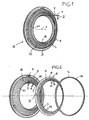
- Fig. 1
- eine Perspektivansicht einer Ausführungsform eines Borstenbremsringes,
- Fiq. 2
- eine Explosionsdarstellung des Borstenbremsrings von Fig. 1 vor dem Zusammenbau,
- Fig. 3
- eine Perspektivteilansicht einer Ausführungsvariante,
- Fig. 4
- eine Perspektivteilansicht einer weiteren Ausführungsvariante,
- Fig. 5
- einen Achsteilschnitt einer weiteren Ausführungsform,
- Fig. 6
- einen Achsteilschnitt einer weiteren Ausführungsform,
- Fig. 7
- einen Achsteilschnitt einer weiteren Ausführungsform, und
- Fig. 8
- eine Frontalansicht eines Teils einer weiteren Ausführungsform eines Borstenbremsrings.
- Fig. 1
- a perspective view of an embodiment of a bristle brake ring,
- Fiq. 2
- an exploded view of the bristle brake ring of Fig. 1 prior to assembly,
- Fig. 3
- a partial perspective view of an embodiment variant,
- Fig. 4
- a partial perspective view of another embodiment,
- Fig. 5
- an axle section of a further embodiment,
- Fig. 6
- an axle section of a further embodiment,
- Fig. 7
- an axle section of another embodiment, and
- Fig. 8
- a frontal view of a portion of another embodiment of a bristle brake ring.
Ein Borstenbremsring R, insbesondere für ein Fadenliefergerät einer Webmaschine
oder Strickmaschine, weist einen ringartigen, formstabilen Träger 3, z.B. ein Kunststoff-Spritzformteil,
auf, in dessen Innendurchmesser eine kreisringartige Bürste B fixiert
ist. Der Träger 3 und die Bürste B haben eine gemeinsame Mittelachse X. Der
Bürstenbremsring R dient zum Erzeugen einer vorbestimmten Fadenspannung in einem
Faden Y, der den Borstenbremsring R im Innendurchmesser durchsetzt, dabei in
linearer Richtung 1 läuft und gleichzeitig in Richtung eines Pfeils umläuft und die
Bürste B kontaktiert.A bristle brake ring R, in particular for a yarn feeding device of a loom
or knitting machine, comprises an annular, dimensionally
Der Ordnung halber wird darauf hingewiesen, dass (Fig. 3) der Borstenbremsring R üblicherweise an einem Speicherkörper K allgemein zylindrischer Form des Fadenliefergeräts koaxial mit der Achse des Speicherkörpers so positioniert ist, dass die Bürste B in einem Anlagebereich P mit vorbestimmter axialer Vorspannung entweder den Frontseitenbereich des Speicherkörpers oder dessen Übergang (Abzugsrand) vom Frontseitenbereich in den Außenumfang oder auch den Außenumfang kontaktiert. Der Faden Y wird zwischen dem Speicherkörper K und der Bürste B umlaufend abgezogen und dabei gebremst.For the sake of order, it is pointed out that (FIG. 3) the bristle brake ring R usually on a storage body K generally cylindrical shape of the yarn feeding device coaxial with the axis of the storage body is positioned so that the Brush B in a contact area P with a predetermined axial bias either the front side area of the storage body or its transition (deduction margin) contacted from the front side area in the outer circumference or the outer circumference. The yarn Y is circulated between the storage body K and the brush B. subtracted and braked.
Im Träger 3 ist an der in der linearen Laufrichtung 1 des Fadens Y vorneliegenden
Außenseite A1 der Bürste B ein umlaufendes Stützelement S angeordnet, an dem
sich die Bürste B bei einer Verformung abstützt, oder ggfs. grundsätzlich mit leichter
Vorspannung gestützt wird. Bei der gezeigten Ausführungsform sind am Träger 3 in
Umfangsrichtung verteilte Rastelemente 4 angeformt, die beispielsweise zum Fixieren
des Trägers 3 in einer nicht gezeigten Halterung dienen. Die Bürste B ist als Kegelstumpf
ausgebildet, der von der Ebene des Trägers 3 in Fig. 1 nach rechts vorsteht.
Das Stützelement S hat ebenfalls kegelstumpfförmige Gestalt und wird z.B. durch einen
Blockierring L positioniert, der entweder am Träger 3 festgelegt ist, oder an den
Rastvorsprüngen 4.In the
Bei der Ausführungsform in Fig. 1 erstreckt sich das Stützelement S nur so weit nach innen, dass ein innerer Teil der Bürste B (die Borstenspitzen) angrenzend an den Innendurchmesser frei bleibt. Das Stützelement S sollte in etwa in Ausrichtung auf den Anlagebereich P (Bremsspalt) frei enden.In the embodiment in Fig. 1, the support element S extends only so far inside, that an inner part of the brush B (the bristle tips) adjacent to the inner diameter remains free. The support element S should be approximately in alignment with the Abutment area P (brake gap) free.
Die Einzelteile des Borstenbremsringes R von Fig. 1 sind in Fig. 2 vor der Montage
erkennbar. Der Träger 3 ist mit der Bürste B und den Rastvorsprüngen 4 ein vorgeformter
Teil. Die Bürste B besteht aus einer Vielzahl elastischer Borsten 5, z.B. natürlichen
Haaren oder tierischer Borsten oder auch synthetischer Borsten wie Nylonborsten
oder dgl., deren freie Borstenspitzen 6 eine z.B. konische Innenfläche der
Bürste B definieren. Die Borsten 5 sind mit ihren Wurzeln 16 (in Fig. 3) in einem Haltebereich
17 des Trägers 3 festgelegt.The individual parts of the bristle brake ring R of Fig. 1 are in Fig. 2 prior to assembly
recognizable. The
Die Außenseite A1, an der das Stützelement S angeordnet ist, weist in Fig. 2 nach
rechts. Das Stützelement S ist beispielsweise ein Lamellenring 8 aus einer Metall-
oder Kunststofffolie geringer Dicke (beispielsweise aus einem Federstahlblech mit einer
Dicke zwischen 0,1 und 0,8 mm) und besitzt beim großdurchmessrigen Ende einen
in Umfangsrichtung geschlossenen Ringabschnitt 9, von dem sich mit der Neigung
des Ringabschnittes 9 fingerartige Lamellen 10 frei auskragend wegerstrecken,
deren Enden mit 11 bezeichnet sind. Die Enden 11 können konvex abgerundet sein.
Die Lamellen 10 sind durch Zwischenräume 13 voneinander getrennt und individuell
biegbar. Die Spitzen 11 der Lamellen definieren einen Stützdurchmesser D, innerhalb
dessen die Außenseite A1 der Bürste B bis zu den Borstenspitzen 6 frei bleibt, wie
dies in Fig. 1 angedeutet ist.The outside A1, on which the support element S is arranged, follows in FIG. 2
right. The support element S is for example a
Der Blockierring kann aus Kunststoff oder Metall bestehen. Er ist bei der gezeigten
Ausführungsform ein Kunststoffring 14 mit annähernd rechteckigem Querschnitt. Im
Träger 3 ist angrenzend an den Haltebereich 17 der Bürste B eine umlaufende Fassung
15 für das großdurchmessrige Ende des Stützelementes S geformt, vor die der
Blockierring L gesetzt wird. Der Blockierring L wird entweder in der Fassung 15 verrastet
oder festgeklebt, oder an der Frontseite des Trägers 3 oder/und mit den Rastvorsprüngen
4 verrastet, um das Stützelement S in der in Fig. 1 gezeigten Position
festzulegen. Zeckmäßig ist das Stützelement schwimmend gelagert, um anpassende
Eigenbewegungen, z.B. Verdrehen, relativ zum Träger 3 und/oder der Bürste B ausführen
zu können.The blocking ring can be made of plastic or metal. He is at the shown
Embodiment a
In Fig. 3 ist zu erkennen, wie die Borsten 5 der Bürste B mit ihren Wurzeln 16 im Haltebereich
17 im Träger 3 festgelegt sind. Das Stützelement S liegt, z.B. vollflächig, an
der Außenseite A1 der Bürste B an, zweckmäßigerweise mit einer Stützfläche F, die
sich bis zu dem Stützdurchmesser D erstreckt. Der Stützdurchmesser D lässt einen
innenliegenden Teil der Bürste B bis zu den Borstenspitzen 6 frei. Am Träger 3 ist ein
Ringwulst 14' angeformt, der als Blockierring L dient, und hinter den das großdurchmessrige
Ende 18 des Stützelementes S, z.B. des Lamellenrings 8 von Fig. 2, eingeschnappt
ist.In Fig. 3 it can be seen how the
Bei der Ausführungsform in Fig. 4 ist der Blockierring L in Form des Kunststoffringes
14 von Fig. 2 an der Frontseite des Trägers 3 festgelegt, z.B. festgeklebt oder verrastet,
um das Stützelement S in der Fassung 15 festzulegen.In the embodiment in Fig. 4, the blocking ring L is in the form of the
Die Bürste B ist als Kegelstumpf mit einem Kegelwinkel α bezüglich der Ebene des
Trägers 3 derart ausgebildet, dass die Bürste B in der linearen Laufrichtung 1 des Fadens
aus der Ringebene des Trägers 3 vorsteht, d.h. in Fig. 4 nach rechts. Die in der
linearen Fadenlaufrichtung vordere Außenseite A1 ist mit einem Kegelwinkel α1 relativ
zur Ebene des Trägers 3 geneigt. Dieser Kegelwinkel α1 entspricht zumindest in
etwa dem Kegelwinkel α2 des Stützelemens. Das Stützelement S hat hier die Form
eines Kegelstumpfmantels, der an der Außenseite A1 anliegen kann, ggfs. mit Vorspannung,
und der in der Fassung 15 positioniert ist.The brush B is a truncated cone with a cone angle α with respect to the plane of
In Fig. 5 ist die Bürste B ein annähernd radialer Kreisring im Träger 3, d.h., die Bürste
erstreckt sich im Wesentlichen in der Ebene des Trägers 3. Die lineare Laufrichtung 1
des Fadens Y ist durch einen Pfeil angedeutet. Das Stützelemente S ist im Träger 3
positioniert und reicht vom Haltebereich der Bürste B im Träger 3 bis zum Stützdurchmesser
D.In Fig. 5, the brush B is an approximately radial annulus in the
In der Ausführungsform in Fig. 6 ist das Stützelemente S zusammen mit der Bürste B
im Träger 3 beispielsweise durch Umspritzen positioniert. Die Bürste ist kegelstumpfförmig,
wie auch das Stützelement S. Gegebenenfalls ist das Stützelement S ein
durchgehender Kegelstumpfmantel aus einer Kunststofffolie oder eine Elastomer-
oder Gummiringmembrane, d.h. aus einem Material hergestellt, das in Richtung des
Pfeiles 1 elastisch nachgibt, jedoch die Bürste B nachgiebig abstützt und dauerhaft
rückstellt.In the embodiment in Fig. 6, the supporting elements S together with the brush B
positioned in the
In Fig. 7 ist die Bürste B im Träger 3 kegelstumpfförmig. Das Stützelement S ist ein
Kreisring parallel in etwa zur Ebene des Trägers 3 und mit seinem großdurchmessrigen
Ende 18 im Träger 3 positioniert, derart, dass es die Bürste B im Wesentlichen
nur mit seinem Stützdurchmesser D beaufschlagt. Das Stützelement S könnte hier ein
durchgehender Kegelstumpfmantel sein (Kunststofffolie oder elastische RingMembrane)
oder ein Lamellenring 8 wie in Fig. 1 und 2.In Fig. 7, the brush B in the
In Fig. 8 ist das Stützelement S zusammengesetzt aus einem kleindurchmessrigen
Stützring 21, der den Stützdurchmesser D definiert, und einem großdurchmessrigen
Haltering 19. Die beiden Ringe 19, 21 sind über Speichen 20 miteinander verbunden.
Dieses Stützelement S ist beispielsweise ein Kunststoffformteil und mittels Rastvorsprüngen
4' des Trägers 3 an diesem positioniert. In dieser Ausführungsform wird die
Bürste B im Wesentlichen nur im Stützdurchmesser D abgestützt.In Fig. 8, the support member S is composed of a small diameter
Support ring 21, which defines the support diameter D, and a large
Grundsätzlich ist es wichtig, dass die Weichheit und Elastizität der Borsten zum
Bremsen nutzbar bleibt, und das Stützelement in den Borstenbremsring baulich möglichst
einfach so eingegliedert wird, dass es die Tendenz der Borsten verhindert, sich
mit zunehmender Gebrauchsdauer bleibend zu verformen, indem die Bürste zumindest
von der in der linearen Fadenlaufrichtung vorderen Außenseite her zurückgestellt
bzw. die Borsten nahe ihren Borstenspitzen wieder aufgerichtet werden, bzw. die freie
Biegelänge der Borsten so verkürzt wird, dass ihre Bremsleistung nicht nachlässt.
Außerdem resultiert aus dem Stützelement S eine steilere Federkennlinie des Borstenbremsringes
R als sie nur mit der Bürste B erzielbar wäre. Eine Nachstellung des
Trägers 3 in Achsrichtung des Speicherkörpers K (Fig. 3) weiter über den Speicherkörper
K erhöht den Kontaktdruck der Bürste dann deutlicher und führt mit denselben
Borsten zu einer höheren Fadenspannung, die mit diesen Borsten ansonsten nicht erzielbar
wäre. Dadurch wird die Einatzbreite des Borstenbremsringes mit nur für bestimmte
Fadenqualitäten, z.B. Multifilamentfäden, geeigneter Borstenart erweitert.Basically it is important that the softness and elasticity of the bristles for
Brakes remains usable, and the support element in the bristle brake ring structurally possible
is simply incorporated so that it prevents the tendency of the bristles themselves
to deform with increasing service life by the brush at least
set back from the front in the direction of the linear yarn running outside
or the bristles are erected near their bristle tips, or the free
Bend length of the bristles is shortened so that their braking performance does not deteriorate.
In addition, results from the support member S, a steeper spring characteristic of the bristle brake ring
R as they would be achievable only with the brush B. A reenactment of the
Claims (10)
- Bristle brake ring (R) for a thread (Y) travelling in linear fashion through the bristle brake ring and circulating internally in the bristle brake ring at the same time, in particular for the storage body of a thread delivery device, with an annular carrier (3) in which the roots (16) of a plurality of elastic bristles (5) are retained in a retaining region (17), which bristles project inwards from the retaining region (7) in overhanging fashion and form a circular ring-shaped, optionally conical brush (B) comprising first and second outer faces (A1, A2), and with an elastic encircling support element (S) which is disposed at the front outside (A1), viewed in the linear thread travel direction (1), of the brush (B) and is concentric with the brush, characterised in that the support element (S) is supported at the actual carrier (3) only at least in the vicinity of the retaining region (17) and extends in overhanging fashion as far as the bristle tips (6) at most, and that the support element (S) is either
a multidisc ring (8) which consists of a metal foil or plastics film and comprises at the large-diameter end a ring region (9), which is continuous in the circumferential direction, and finger-shaped discs (10) which extend freely inwards from the ring region (9) and are separated by interspaces (13),
or a truncated-cone envelope, which is closed in the circumferential direction, of a plastics film or an elastomer or rubber ring membrane,
or a small-diameter support ring (21), a large-diameter retaining ring (19) and spokes (20) connecting the rings (21, 19). - Bristle brake ring according to Claim 1, characterised in that the outside (A1) of the brush (B) is a truncated-cone envelope, and that the support element (S) is also formed as a truncated-cone envelope.
- Bristle brake ring according to Claim 2, characterised in that the cone angle (α1, α2) of the two truncated cones are at least largely identical.
- Bristle brake ring according to Claim 1, characterised in that the discs (10) of the multidisc ring (8) are disposed approximately radially or at an inclination, preferably at an inclination in the direction of circulation (2) of the thread (Y).
- Bristle brake ring according to Claim 1, characterised in that the discs of the multidisc ring comprise rounded ends (11).
- Bristle brake ring according to Claim 1, characterised in that the multidisc ring (8) is formed from an open-ended strip, the ends (12) of which are connected together.
- Bristle brake ring according to Claim 1, characterised in that the support element (S) is disposed in floating fashion at the carrier (3).
- Bristle brake ring according to Claim 1, characterised in that the support element (S) is positioned by means of a locking ring (L) which is secured to the carrier (3).
- Bristle brake ring according to Claim 8, characterised in that a mount (15) for the large-diameter end region (18) of the support element (S) is formed at the carrier (3), and that detent elements (4, 4') are provided for the locking ring (L) in or adjacent to the mount (15), preferably for a releasable snap-action fastening of the locking ring (L).
- Bristle brake ring according to Claim 1, characterised in that the support element (S) is inserted behind an annular bead (14'), adjacent to the retaining region (7), of the carrier (3).
Applications Claiming Priority (2)
| Application Number | Priority Date | Filing Date | Title |
|---|---|---|---|
| DE10135628 | 2001-07-20 | ||
| DE2001135628 DE10135628A1 (en) | 2001-07-20 | 2001-07-20 | Bristle brake ring |
Publications (3)
| Publication Number | Publication Date |
|---|---|
| EP1277688A2 EP1277688A2 (en) | 2003-01-22 |
| EP1277688A3 EP1277688A3 (en) | 2003-04-16 |
| EP1277688B1 true EP1277688B1 (en) | 2005-10-05 |
Family
ID=7692663
Family Applications (1)
| Application Number | Title | Priority Date | Filing Date |
|---|---|---|---|
| EP20020015674 Expired - Lifetime EP1277688B1 (en) | 2001-07-20 | 2002-07-17 | Brush brake ring |
Country Status (2)
| Country | Link |
|---|---|
| EP (1) | EP1277688B1 (en) |
| DE (2) | DE10135628A1 (en) |
Families Citing this family (2)
| Publication number | Priority date | Publication date | Assignee | Title |
|---|---|---|---|---|
| DE102004045497A1 (en) * | 2004-09-20 | 2006-03-30 | Iro Ab | Yarn feeder |
| DE102006001125A1 (en) * | 2006-01-09 | 2007-07-12 | Iro Ab | Yarn feeding device and brake body |
Family Cites Families (5)
| Publication number | Priority date | Publication date | Assignee | Title |
|---|---|---|---|---|
| DE2036040A1 (en) * | 1970-07-21 | 1972-02-03 | Glanzstoff AG, 5600 Wuppertal | Device for applying a wire helix to a thin wire rope |
| DE2555802A1 (en) * | 1975-12-11 | 1977-06-23 | Lawson Hemphill | Yarn tensioner for yarn storage drum - has two or more tensioning rings arranged axially over one another around drum |
| IT1133910B (en) * | 1980-10-15 | 1986-07-24 | Roy Electrotex Spa | Yarn feeder and tensioner |
| DE9015048U1 (en) * | 1990-11-02 | 1992-02-27 | Sobrevin Societe De Brevets Industriels-Etablissement, Vaduz, Li | |
| IT1295624B1 (en) * | 1997-10-15 | 1999-05-24 | Roj Electrotex Nuova Srl | BRAKING DEVICE FOR YARN IN WEFT FEEDERS AND BRAKING ELEMENT FOR SAID DEVICE |
-
2001
- 2001-07-20 DE DE2001135628 patent/DE10135628A1/en not_active Withdrawn
-
2002
- 2002-07-17 DE DE50204437T patent/DE50204437D1/en not_active Expired - Fee Related
- 2002-07-17 EP EP20020015674 patent/EP1277688B1/en not_active Expired - Lifetime
Also Published As
| Publication number | Publication date |
|---|---|
| DE10135628A1 (en) | 2003-02-06 |
| DE50204437D1 (en) | 2005-11-10 |
| EP1277688A3 (en) | 2003-04-16 |
| EP1277688A2 (en) | 2003-01-22 |
Similar Documents
| Publication | Publication Date | Title |
|---|---|---|
| EP0963335A1 (en) | Thread delivery device and thread brake | |
| DE112012002293B4 (en) | Cord length adjustment device | |
| DE2803925C2 (en) | Opening roller for open-end spinning machines | |
| DE102005007842A1 (en) | Yarn braking device | |
| DE2841926A1 (en) | DEVICE FOR CONTROLLING THE PULL-OFF TENSION OF THE YARN OR THREAD FROM A SUPPORTING BODY | |
| DE3431335C2 (en) | ||
| EP1277688B1 (en) | Brush brake ring | |
| DE102004038165B4 (en) | Use of a roller for spreading a running web | |
| DE2612475A1 (en) | DEVICE FOR UNWINDING WIRE OR THREAD FROM A SPOOL | |
| DE2131128C3 (en) | Ribbon take-up device | |
| DE3205450A1 (en) | Automatic positively controlled yarn-feed device for use in a knitting machine | |
| DD268488A5 (en) | THREAD DELIVERY DEVICE FOR KNITTING MACHINES | |
| DE2047214A1 (en) | Adjustable holder for spools of thread | |
| EP0396216B1 (en) | Guiding device for guiding webs, paricularly textile webs | |
| DE2155292C3 (en) | Device for suppressing undesired changes in shape of magnetic disks during the operation of a magnetic disk storage | |
| EP1121318B1 (en) | Yarn tension device and yarn feeding apparatus with a yarn tension device | |
| DE3147966A1 (en) | Friction false twister | |
| DE2827814C3 (en) | Drainage aid for pulling threads from spools of all kinds | |
| DE3043039C2 (en) | Pen-shaped writing insert | |
| CH306338A (en) | Double wire spindle. | |
| EP0889843B1 (en) | Thread feed | |
| DE102004045497A1 (en) | Yarn feeder | |
| CH643189A5 (en) | Running roller | |
| EP0291731B1 (en) | Presser for affixing a metal foil to bottle neck and head, in a labelling machine | |
| DE2255607C3 (en) |
Legal Events
| Date | Code | Title | Description |
|---|---|---|---|
| PUAI | Public reference made under article 153(3) epc to a published international application that has entered the european phase |
Free format text: ORIGINAL CODE: 0009012 |
|
| AK | Designated contracting states |
Kind code of ref document: A2 Designated state(s): AT BE BG CH CY CZ DE DK EE ES FI FR GB GR IE IT LI LU MC NL PT SE SK TR |
|
| AX | Request for extension of the european patent |
Free format text: AL;LT;LV;MK;RO;SI |
|
| PUAL | Search report despatched |
Free format text: ORIGINAL CODE: 0009013 |
|
| AK | Designated contracting states |
Designated state(s): AT BE BG CH CY CZ DE DK EE ES FI FR GB GR IE IT LI LU MC NL PT SE SK TR |
|
| AX | Request for extension of the european patent |
Extension state: AL LT LV MK RO SI |
|
| 17P | Request for examination filed |
Effective date: 20031015 |
|
| AKX | Designation fees paid |
Designated state(s): BE CH DE IT LI TR |
|
| 17Q | First examination report despatched |
Effective date: 20040716 |
|
| GRAP | Despatch of communication of intention to grant a patent |
Free format text: ORIGINAL CODE: EPIDOSNIGR1 |
|
| GRAS | Grant fee paid |
Free format text: ORIGINAL CODE: EPIDOSNIGR3 |
|
| GRAA | (expected) grant |
Free format text: ORIGINAL CODE: 0009210 |
|
| AK | Designated contracting states |
Kind code of ref document: B1 Designated state(s): BE CH DE IT LI TR |
|
| REG | Reference to a national code |
Ref country code: CH Ref legal event code: EP |
|
| REF | Corresponds to: |
Ref document number: 50204437 Country of ref document: DE Date of ref document: 20051110 Kind code of ref document: P |
|
| PG25 | Lapsed in a contracting state [announced via postgrant information from national office to epo] |
Ref country code: LI Free format text: LAPSE BECAUSE OF NON-PAYMENT OF DUE FEES Effective date: 20060731 Ref country code: BE Free format text: LAPSE BECAUSE OF NON-PAYMENT OF DUE FEES Effective date: 20060731 Ref country code: CH Free format text: LAPSE BECAUSE OF NON-PAYMENT OF DUE FEES Effective date: 20060731 |
|
| PLBE | No opposition filed within time limit |
Free format text: ORIGINAL CODE: 0009261 |
|
| STAA | Information on the status of an ep patent application or granted ep patent |
Free format text: STATUS: NO OPPOSITION FILED WITHIN TIME LIMIT |
|
| 26N | No opposition filed |
Effective date: 20060706 |
|
| PG25 | Lapsed in a contracting state [announced via postgrant information from national office to epo] |
Ref country code: DE Free format text: LAPSE BECAUSE OF NON-PAYMENT OF DUE FEES Effective date: 20070201 |
|
| REG | Reference to a national code |
Ref country code: CH Ref legal event code: PL |
|
| BERE | Be: lapsed |
Owner name: IROPA A.G. Effective date: 20060731 |
|
| PG25 | Lapsed in a contracting state [announced via postgrant information from national office to epo] |
Ref country code: TR Free format text: LAPSE BECAUSE OF FAILURE TO SUBMIT A TRANSLATION OF THE DESCRIPTION OR TO PAY THE FEE WITHIN THE PRESCRIBED TIME-LIMIT Effective date: 20051005 |
|
| PGFP | Annual fee paid to national office [announced via postgrant information from national office to epo] |
Ref country code: IT Payment date: 20190723 Year of fee payment: 18 |
|
| PG25 | Lapsed in a contracting state [announced via postgrant information from national office to epo] |
Ref country code: IT Free format text: LAPSE BECAUSE OF NON-PAYMENT OF DUE FEES Effective date: 20200717 |