EP1277621A1 - Stossfänger für ein Kraftfahrzeug - Google Patents
Stossfänger für ein Kraftfahrzeug Download PDFInfo
- Publication number
- EP1277621A1 EP1277621A1 EP01117242A EP01117242A EP1277621A1 EP 1277621 A1 EP1277621 A1 EP 1277621A1 EP 01117242 A EP01117242 A EP 01117242A EP 01117242 A EP01117242 A EP 01117242A EP 1277621 A1 EP1277621 A1 EP 1277621A1
- Authority
- EP
- European Patent Office
- Prior art keywords
- bumper
- cross member
- motor vehicle
- reinforcing component
- shell section
- Prior art date
- Legal status (The legal status is an assumption and is not a legal conclusion. Google has not performed a legal analysis and makes no representation as to the accuracy of the status listed.)
- Granted
Links
- 230000003014 reinforcing effect Effects 0.000 claims description 19
- 239000003351 stiffener Substances 0.000 abstract 4
- 230000002787 reinforcement Effects 0.000 description 20
- 230000009467 reduction Effects 0.000 description 4
- 238000003466 welding Methods 0.000 description 4
- 239000006096 absorbing agent Substances 0.000 description 3
- 238000004519 manufacturing process Methods 0.000 description 3
- 238000000034 method Methods 0.000 description 3
- 229910000831 Steel Inorganic materials 0.000 description 2
- 230000008878 coupling Effects 0.000 description 2
- 238000010168 coupling process Methods 0.000 description 2
- 238000005859 coupling reaction Methods 0.000 description 2
- 238000005304 joining Methods 0.000 description 2
- 239000004033 plastic Substances 0.000 description 2
- 230000008569 process Effects 0.000 description 2
- 239000010959 steel Substances 0.000 description 2
- 239000011358 absorbing material Substances 0.000 description 1
- 238000004026 adhesive bonding Methods 0.000 description 1
- 238000000418 atomic force spectrum Methods 0.000 description 1
- 230000004888 barrier function Effects 0.000 description 1
- 238000005452 bending Methods 0.000 description 1
- 238000010276 construction Methods 0.000 description 1
- 238000005516 engineering process Methods 0.000 description 1
- 239000000835 fiber Substances 0.000 description 1
- 230000007935 neutral effect Effects 0.000 description 1
- 230000035515 penetration Effects 0.000 description 1
- 239000002984 plastic foam Substances 0.000 description 1
- 230000008439 repair process Effects 0.000 description 1
- 230000007480 spreading Effects 0.000 description 1
- 238000003892 spreading Methods 0.000 description 1
- 230000001131 transforming effect Effects 0.000 description 1
Images
Classifications
-
- B—PERFORMING OPERATIONS; TRANSPORTING
- B60—VEHICLES IN GENERAL
- B60R—VEHICLES, VEHICLE FITTINGS, OR VEHICLE PARTS, NOT OTHERWISE PROVIDED FOR
- B60R19/00—Wheel guards; Radiator guards, e.g. grilles; Obstruction removers; Fittings damping bouncing force in collisions
- B60R19/02—Bumpers, i.e. impact receiving or absorbing members for protecting vehicles or fending off blows from other vehicles or objects
- B60R19/18—Bumpers, i.e. impact receiving or absorbing members for protecting vehicles or fending off blows from other vehicles or objects characterised by the cross-section; Means within the bumper to absorb impact
-
- B—PERFORMING OPERATIONS; TRANSPORTING
- B60—VEHICLES IN GENERAL
- B60R—VEHICLES, VEHICLE FITTINGS, OR VEHICLE PARTS, NOT OTHERWISE PROVIDED FOR
- B60R19/00—Wheel guards; Radiator guards, e.g. grilles; Obstruction removers; Fittings damping bouncing force in collisions
- B60R19/02—Bumpers, i.e. impact receiving or absorbing members for protecting vehicles or fending off blows from other vehicles or objects
- B60R19/24—Arrangements for mounting bumpers on vehicles
-
- B—PERFORMING OPERATIONS; TRANSPORTING
- B60—VEHICLES IN GENERAL
- B60R—VEHICLES, VEHICLE FITTINGS, OR VEHICLE PARTS, NOT OTHERWISE PROVIDED FOR
- B60R19/00—Wheel guards; Radiator guards, e.g. grilles; Obstruction removers; Fittings damping bouncing force in collisions
- B60R19/02—Bumpers, i.e. impact receiving or absorbing members for protecting vehicles or fending off blows from other vehicles or objects
- B60R19/18—Bumpers, i.e. impact receiving or absorbing members for protecting vehicles or fending off blows from other vehicles or objects characterised by the cross-section; Means within the bumper to absorb impact
- B60R2019/1806—Structural beams therefor, e.g. shock-absorbing
- B60R2019/1813—Structural beams therefor, e.g. shock-absorbing made of metal
Definitions
- the invention relates to a bumper for a motor vehicle according to the Features in the preamble of claim 1.
- Bumpers are located across the front and rear of a motor vehicle between the the plastic casing and the frame of the Motor vehicle arranged. They are designed to help keep the vehicle structure no damage in the event of a low-speed impact it bears. Often there are still between the cross member and the side members Impact absorbers, so-called crash boxes switched. Absorb the crash boxes the energy resulting from an impact by transforming it into work is converted.
- DE 44 13 641 C1 makes a bumper part of the prior art with a cross member designed as an energy absorber.
- the cross member is formed in two parts and has a back part with a C-profile for attachment on the vehicle body and a flat covering the back part Closing part.
- An impact body is arranged on the front of the cross member in the form of an extending over the length of the cross member Full profile made of an energy absorbing material, which is preferably made of Plastic foam or a honeycomb structure made of plastic.
- DE 196 43 049 A1 discloses a bumper, the cross member of which a hollow profile constructed from two U-shaped profiled half-shells is. As reinforcement, inserts are arranged in the half shells the neutral fiber is provided with side cuts. additionally reinforcement angle strips are arranged at the fastening points.
- the different bumpers perform their functions differently well. to Limitation of damage in accidents with low speed serve in reinforcements integrated into the crossmember. These support e.g. at a Impact at 4 km / h in tests against a pendulum or against a barrier No damage to the crossmember and the vehicle.
- the object of the invention is based on the prior art based on a bumper with a stiffness and strength behavior to create improved cross member, which in particular Use in rear bumpers allows damage limitation.
- a reinforcing component preferably consists of sheet steel.
- the production is economically and cost-effectively possible in the course of mass production.
- the cross member and the reinforcement components can be made in separate manufacturing processes getting produced. Then the reinforcement components positioned in the cross member and joined with this.
- the geometrical Configuration in terms of section modulus as well as strength and Stiffness behavior of the reinforcement components can depend on the respective Use in the crossmember. Depending on the vehicle requirements can have several reinforcement components on the vehicle technically required positions are integrated.
- the geometry of the reinforcement components can be of various types. For the In practice, oval, round or rectangular cylinder cross sections are conceivable. she are partially integrated into the crossmember and enable targeted Adjustment regarding the stiffness and strength behavior as well as the Bending course on impact. The basic concept remains with different ones Vehicle types the same. An adjustment of the load behavior is done by coordinating the number, geometry and position of the reinforcement components.
- the reinforcement components run in combination with the cross member shell to double and increase the wall thickness on partially critical Positioning the bumper and thus for a targeted coordination of the overall system on the force profiles to be expected in the operational load case.
- the shell portion of the cross member a central web with two legs, the reinforcing component a configuratively adapted to the web of the shell section Has end wall that contacts the web.
- the reinforcement component joined with the web on the inside of the shell section be, for example, welding technology.
- the reinforcing member can Make partial or full contact with the bar. As particularly advantageous in practice becomes a full-surface contact of the end face of the reinforcing component viewed on the jetty.
- the contacting surfaces are in their Contour coordinated.
- FIG. 3 An advantageous embodiment of the inventive concept characterized Claim 3, wherein the shell portion has flanges and on Reinforcing component a collar is provided, which is joined to the flanges is.
- the joining can be realized by means of spot welding or seam welding his. Other joining techniques such as gluing or clinching are also conceivable.
- the flanges are preferably at the ends of the legs to the outside directed. Basically, the flanges can also with respect to the Shell body to be directed towards each other inwards.
- the reinforcement component can be tempered after the deep-drawing process (Claim 4). This is particularly the case with high loads or demands the crash behavior as in the pile test advantageous.
- the local attachment of the reinforcement components leads to a pile test a reduction in the depth of penetration of the pile on impact.
- the invention The bumper has a load-bearing and functional function Construction of the cross member. A redirection of the forces from the cross member on the impact absorbers / crash boxes is guaranteed. This leads to a Reduction of damage and ultimately to reduce any repair costs. Furthermore, a reduction in the weight of the cross member can be achieved. As the reinforcement components increase the resistance a reduction in wall thickness on other components of the bumper arrangement possible, which can be advantageous in terms of weight. moreover the reinforcement components take on the function of a striking plate for the bowl-shaped configured cross member, so that opening or spreading the leg to the outside is avoided in the event of an impact.
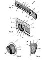
- FIG. 1 shows a section of a bumper 1 for a motor vehicle in a view from behind, that is seen from the motor vehicle.
- the bumper 1 comprises a transverse to the longitudinal beams of the Motor vehicle definable cross member 2, the essential part its length is a shell section configured approximately U-shaped in cross section 3 has.
- the shell section 3 has a central web 4 two legs 5, 6 and adjoining them, in the exemplary embodiment outward flanges 7, 8.
- connection area 11 can be seen in FIG. 1 to the crash box or a side member.
- the connection area 11 includes a bolt-like coupling member 12 and a stop plate 13 which with the Cross member 2 is screwed.
- the connection area 11 In the connection area 11 are the upper and lower leg 5, 6 retracted, which supports stability.
- a cup-shaped deep-drawn reinforcing component 14 incorporated (see also Figure 2).
- the reinforcement component is a deep-drawn sheet steel product, which has been tempered after the deep-drawing process.
- the reinforcement component 14 has a round cylinder section 15 with a configurative to the Web 4 of the shell section 3 adapted end wall 16 ( Figures 3 and 4).
- the reinforcing component 14 is toward the web 4 through the end wall 16 closed, whereas it is open at the motor vehicle end 17 and has a circumferential radially outwardly directed collar 18.
- the End wall 16 contacts the web 4 over the entire surface and is welded to it together. It can be seen in particular from FIG. 4 that the End wall 16 runs obliquely backwards in the image plane from top to bottom.
- the reinforcing component 14 lies with the upper section 19 and the lower Section 20 of the collar 18 on the flanges 7 and 8 respectively preferably specified there by welding. That way it takes over the reinforcing member 14 acts as a striker and prevents in the event of an impact, the legs 5, 6 are spread apart.
- the reinforcing component 14 integrated in the shell section 3 leads to a partial reinforcement of the cross member 2 in critical areas.
- the cross member 2 has an improved rigidity and strength behavior on, so that the bumper 1 overall reduces the Damage to the motor vehicle in the event of an impact can contribute.
Landscapes
- Engineering & Computer Science (AREA)
- Mechanical Engineering (AREA)
- Body Structure For Vehicles (AREA)
- Vibration Dampers (AREA)
- Arrangement Or Mounting Of Propulsion Units For Vehicles (AREA)
- Reciprocating, Oscillating Or Vibrating Motors (AREA)
Abstract
Description
- Figur 1
- in perspektivischer Darstellungsweise ein Teilstück eines Querträgers;
- Figur 2
- vergrößert einen Ausschnitt aus dem Querträger mit der Darstellung eines Verstärkungsbauteils;
- Figur 3
- die perspektivische Darstellung eines Verstärkungsbauteils und
- Figur 4
- das Verstärkungsbauteil gemäß Figur 3 in der Seitenansicht.
- 1 -
- Stoßfänger
- 2 -
- Querträger
- 3 -
- Schalenabschnitt
- 4 -
- Steg
- 5 -
- Schenkel
- 6 -
- Schenkel
- 7 -
- Flansch
- 8 -
- Flansch
- 9 -
- Ende v. 2
- 10 -
- Schließblech
- 11 -
- Anbindungsbereich
- 12 -
- Koppelglied
- 13 -
- Anschlagplatte
- 14 -
- Verstärkungsbauteil
- 15 -
- Zylinderabschnitt
- 16 -
- Stirnwand
- 17-
- Ende v. 14
- 18 -
- Kragen
- 19 -
- Abschnitt v. 18
- 20 -
- Abschnitt v. 18
Claims (4)
- Stoßfänger für ein Kraftfahrzeug mit einem quer zu den Längsträgern des Kraftfahrzeugrahmens festlegbaren Querträger (2), welcher zumindest über einen wesentlichen Teil seiner Länge einen Schalenabschnitt (3) aufweist, dadurch gekennzeichnet, dass in den Schalenabschnitt (3) zumindest ein napfartig gestaltetes tiefgezogenes Verstärkungsbauteil (14) eingegliedert ist.
- Stoßfänger nach Anspruch 1, dadurch gekennzeichnet, dass der Schalenabschnitt (3) einen zentralen Steg (4) mit zwei Schenkeln (5, 6) aufweist und das Verstärkungsbauteil (14) eine konfigurativ an den Steg (4) des Schalenabschnitt (3) angepasste Stirnwand (16) besitzt, die den Steg (4) kontaktiert.
- Stoßfänger nach Anspruch 1 oder 2, dadurch gekennzeichnet, dass der Schalenabschnitt (3) Flansche (7, 8) aufweist und am Verstärkungsbauteil (14) ein Kragen (18) vorgesehen ist, der mit den Flanschen (7, 8) gefügt ist.
- Stoßfänger nach einem der Ansprüche 1 bis 4, dadurch gekennzeichnet,dass das Verstärkungsbauteil (14) vergütet ist.
Priority Applications (5)
| Application Number | Priority Date | Filing Date | Title |
|---|---|---|---|
| DE50101004T DE50101004D1 (de) | 2001-07-17 | 2001-07-17 | Stossfänger für ein Kraftfahrzeug |
| EP01117242A EP1277621B1 (de) | 2001-07-17 | 2001-07-17 | Stossfänger für ein Kraftfahrzeug |
| AT01117242T ATE254549T1 (de) | 2001-07-17 | 2001-07-17 | Stossfänger für ein kraftfahrzeug |
| CZ20013252A CZ296869B6 (cs) | 2001-07-17 | 2001-09-10 | Nárazník pro motorové vozidlo |
| US09/978,884 US6623055B2 (en) | 2001-07-17 | 2001-10-16 | Bumper for a motor vehicle |
Applications Claiming Priority (1)
| Application Number | Priority Date | Filing Date | Title |
|---|---|---|---|
| EP01117242A EP1277621B1 (de) | 2001-07-17 | 2001-07-17 | Stossfänger für ein Kraftfahrzeug |
Publications (2)
| Publication Number | Publication Date |
|---|---|
| EP1277621A1 true EP1277621A1 (de) | 2003-01-22 |
| EP1277621B1 EP1277621B1 (de) | 2003-11-19 |
Family
ID=8178054
Family Applications (1)
| Application Number | Title | Priority Date | Filing Date |
|---|---|---|---|
| EP01117242A Expired - Lifetime EP1277621B1 (de) | 2001-07-17 | 2001-07-17 | Stossfänger für ein Kraftfahrzeug |
Country Status (5)
| Country | Link |
|---|---|
| US (1) | US6623055B2 (de) |
| EP (1) | EP1277621B1 (de) |
| AT (1) | ATE254549T1 (de) |
| CZ (1) | CZ296869B6 (de) |
| DE (1) | DE50101004D1 (de) |
Families Citing this family (7)
| Publication number | Priority date | Publication date | Assignee | Title |
|---|---|---|---|---|
| WO2005043373A1 (en) * | 2003-10-31 | 2005-05-12 | Koninklijke Philips Electronics, N.V. | Method and system for organizing content on a time axis |
| DE102007040942A1 (de) * | 2007-08-30 | 2009-03-05 | GM Global Technology Operations, Inc., Detroit | Aufprallbegrenzungssystem eines Fahrzeugs |
| US7866716B2 (en) | 2008-04-08 | 2011-01-11 | Flex-N-Gate Corporation | Energy absorber for vehicle |
| DE102011051965A1 (de) | 2011-07-20 | 2013-01-24 | Benteler Automobiltechnik Gmbh | Verfahren zur Herstellung eines rohrförmigen Strukturbauteils für ein Kraftfahrzeug und Strukturbauteil |
| US10065587B2 (en) | 2015-11-23 | 2018-09-04 | Flex|N|Gate Corporation | Multi-layer energy absorber |
| US20190034841A1 (en) * | 2017-07-31 | 2019-01-31 | Accenture Global Solutions Limited | Determining digital value of a digital technology initiative |
| USD1022814S1 (en) * | 2022-03-31 | 2024-04-16 | Zoox, Inc. | Grille assembly |
Citations (6)
| Publication number | Priority date | Publication date | Assignee | Title |
|---|---|---|---|---|
| DE4307836A1 (de) * | 1992-03-25 | 1993-09-30 | Volkswagen Ag | Träger zur Energieabsorption bei quer zu seiner Längsrichtung erfolgenden Stößen |
| DE4413641C1 (de) | 1994-04-20 | 1995-06-29 | Daimler Benz Ag | Stoßfänger für Kraftfahrzeuge |
| DE19643049A1 (de) | 1996-10-18 | 1998-04-23 | Daimler Benz Ag | Stoßfänger und Unterfahrschutz für ein Kraftfahrzeug, insbesondere ein Nutzkraftfahrzeug |
| DE19849358A1 (de) * | 1998-10-27 | 2000-05-11 | Benteler Werke Ag | Stoßfänger für Kraftfahrzeuge |
| US6179355B1 (en) * | 1998-12-18 | 2001-01-30 | Ford Global Technologies, Inc. | Automotive vehicle bumper assembly |
| US6199937B1 (en) * | 1999-02-01 | 2001-03-13 | Visteon Global Technologies, Inc. | Energy absorbing pocket member |
Family Cites Families (10)
| Publication number | Priority date | Publication date | Assignee | Title |
|---|---|---|---|---|
| US3897095A (en) * | 1973-12-07 | 1975-07-29 | Ford Motor Co | Resilient bumper assembly |
| DE3419165A1 (de) * | 1984-05-23 | 1985-11-28 | Boge Gmbh, 5208 Eitorf | Pralldaempfer mit zwei ineinander schieblichen rohren |
| JPS62128852A (ja) * | 1985-11-29 | 1987-06-11 | Honda Motor Co Ltd | 自動車用合成樹脂製バンパ |
| DE68907880T2 (de) * | 1988-12-24 | 1993-11-04 | Minoru Sangyo | Stossstange aus kunststoff. |
| US5031947A (en) * | 1990-01-05 | 1991-07-16 | Chen Ming Tang | Vehicular bumper assembly with multibuffer construction |
| JP2596056Y2 (ja) * | 1993-01-25 | 1999-06-07 | 富士重工業株式会社 | 車両のフロントエンド部モジュールキャリア構造 |
| DE19511868A1 (de) * | 1995-03-31 | 1996-10-02 | Daimler Benz Ag | Stoßstange |
| FR2777615B1 (fr) * | 1998-04-15 | 2000-12-29 | Plastic Omnium Cie | Absorbeur de chocs a section ondulee et pare-chocs muni d'un tel absorbeur de chocs |
| DE10002379B4 (de) * | 2000-01-20 | 2006-01-19 | Benteler Ag | Stoßfänger |
| US6406079B2 (en) * | 2000-07-14 | 2002-06-18 | Kyoraku Co., Ltd. | Automobile bumper core |
-
2001
- 2001-07-17 AT AT01117242T patent/ATE254549T1/de not_active IP Right Cessation
- 2001-07-17 DE DE50101004T patent/DE50101004D1/de not_active Expired - Fee Related
- 2001-07-17 EP EP01117242A patent/EP1277621B1/de not_active Expired - Lifetime
- 2001-09-10 CZ CZ20013252A patent/CZ296869B6/cs not_active IP Right Cessation
- 2001-10-16 US US09/978,884 patent/US6623055B2/en not_active Expired - Fee Related
Patent Citations (6)
| Publication number | Priority date | Publication date | Assignee | Title |
|---|---|---|---|---|
| DE4307836A1 (de) * | 1992-03-25 | 1993-09-30 | Volkswagen Ag | Träger zur Energieabsorption bei quer zu seiner Längsrichtung erfolgenden Stößen |
| DE4413641C1 (de) | 1994-04-20 | 1995-06-29 | Daimler Benz Ag | Stoßfänger für Kraftfahrzeuge |
| DE19643049A1 (de) | 1996-10-18 | 1998-04-23 | Daimler Benz Ag | Stoßfänger und Unterfahrschutz für ein Kraftfahrzeug, insbesondere ein Nutzkraftfahrzeug |
| DE19849358A1 (de) * | 1998-10-27 | 2000-05-11 | Benteler Werke Ag | Stoßfänger für Kraftfahrzeuge |
| US6179355B1 (en) * | 1998-12-18 | 2001-01-30 | Ford Global Technologies, Inc. | Automotive vehicle bumper assembly |
| US6199937B1 (en) * | 1999-02-01 | 2001-03-13 | Visteon Global Technologies, Inc. | Energy absorbing pocket member |
Also Published As
| Publication number | Publication date |
|---|---|
| EP1277621B1 (de) | 2003-11-19 |
| ATE254549T1 (de) | 2003-12-15 |
| CZ296869B6 (cs) | 2006-07-12 |
| DE50101004D1 (de) | 2003-12-24 |
| US6623055B2 (en) | 2003-09-23 |
| CZ20013252A3 (cs) | 2003-03-12 |
| US20030015880A1 (en) | 2003-01-23 |
Similar Documents
| Publication | Publication Date | Title |
|---|---|---|
| DE102007035483B4 (de) | Crasheinrichtung | |
| DE10314905B4 (de) | Stoßfängersystem für engen Bauraum | |
| DE102004039592B4 (de) | Crashbox | |
| DE102009004827B4 (de) | Stoßfänger | |
| DE102013111189B4 (de) | Stoßfängerquerträger für ein Kraftfahrzeug | |
| WO2020035397A1 (de) | Stossfänger für ein kraftfahrzeug | |
| DE102007030929B9 (de) | Achsträger für Kraftfahrzeuge | |
| DE102021102366B4 (de) | Stoßfängeranordnung für ein Kraftfahrzeug | |
| DE4340033C2 (de) | Seitenaufprallträger | |
| DE102008059748A1 (de) | Stoßfänger | |
| DE102020104097B4 (de) | Kraftfahrzeug-Stoßfänger | |
| DE10108279A1 (de) | Aufprallabsorbierende Struktur eines Fahrzeuges | |
| DE102013001668B4 (de) | Karosseriestruktur eines Kraftfahrzeugs und Kraftfahrzeug mit einer derartigen Karosseriestruktur | |
| DE10048902C1 (de) | Stossfängeranordnung | |
| DE202008017596U1 (de) | Formbauteil aus Stahlblech | |
| EP1277621B1 (de) | Stossfänger für ein Kraftfahrzeug | |
| DE102006041092A1 (de) | Knautschzone einer Karosserie eines Kraftwagens | |
| DE19637243A1 (de) | Träger für ein Kraftfahrzeug | |
| DE102009021964A1 (de) | Hohlprofil für eine Fahrzeugkarosserie | |
| EP4357203B1 (de) | Stossfängeranordnung mit doppelquerträger und abschleppöse | |
| DE10226756B4 (de) | Stoßfänger für ein Kraftfahrzeug | |
| DE102021126164B4 (de) | Stoßfängerquerträger für ein Fahrzeug | |
| DE102004046585B4 (de) | Stoßfängervorrichtung | |
| DE10108352B4 (de) | Strukturbauelement für den Fahrzeugbau | |
| EP4342741A1 (de) | Stossfängeranordnung für ein kraftfahrzeug |
Legal Events
| Date | Code | Title | Description |
|---|---|---|---|
| PUAI | Public reference made under article 153(3) epc to a published international application that has entered the european phase |
Free format text: ORIGINAL CODE: 0009012 |
|
| 17P | Request for examination filed |
Effective date: 20020109 |
|
| AK | Designated contracting states |
Kind code of ref document: A1 Designated state(s): AT BE CH CY DE DK ES FI FR GB GR IE IT LI LU MC NL PT SE TR |
|
| AX | Request for extension of the european patent |
Free format text: AL;LT;LV;MK;RO;SI |
|
| GRAH | Despatch of communication of intention to grant a patent |
Free format text: ORIGINAL CODE: EPIDOS IGRA |
|
| GRAS | Grant fee paid |
Free format text: ORIGINAL CODE: EPIDOSNIGR3 |
|
| RAP1 | Party data changed (applicant data changed or rights of an application transferred) |
Owner name: BENTELER AUTOMOBILTECHNIK GMBH |
|
| GRAA | (expected) grant |
Free format text: ORIGINAL CODE: 0009210 |
|
| AKX | Designation fees paid |
Designated state(s): AT BE CH CY DE DK ES FI FR GB GR IE IT LI LU MC NL PT SE TR |
|
| AK | Designated contracting states |
Kind code of ref document: B1 Designated state(s): AT BE CH CY DE DK ES FI FR GB GR IE IT LI LU MC NL PT SE TR |
|
| PG25 | Lapsed in a contracting state [announced via postgrant information from national office to epo] |
Ref country code: CY Free format text: LAPSE BECAUSE OF FAILURE TO SUBMIT A TRANSLATION OF THE DESCRIPTION OR TO PAY THE FEE WITHIN THE PRESCRIBED TIME-LIMIT Effective date: 20031119 Ref country code: TR Free format text: LAPSE BECAUSE OF FAILURE TO SUBMIT A TRANSLATION OF THE DESCRIPTION OR TO PAY THE FEE WITHIN THE PRESCRIBED TIME-LIMIT Effective date: 20031119 Ref country code: GB Free format text: LAPSE BECAUSE OF FAILURE TO SUBMIT A TRANSLATION OF THE DESCRIPTION OR TO PAY THE FEE WITHIN THE PRESCRIBED TIME-LIMIT Effective date: 20031119 Ref country code: IE Free format text: LAPSE BECAUSE OF FAILURE TO SUBMIT A TRANSLATION OF THE DESCRIPTION OR TO PAY THE FEE WITHIN THE PRESCRIBED TIME-LIMIT Effective date: 20031119 Ref country code: NL Free format text: LAPSE BECAUSE OF FAILURE TO SUBMIT A TRANSLATION OF THE DESCRIPTION OR TO PAY THE FEE WITHIN THE PRESCRIBED TIME-LIMIT Effective date: 20031119 Ref country code: FI Free format text: LAPSE BECAUSE OF FAILURE TO SUBMIT A TRANSLATION OF THE DESCRIPTION OR TO PAY THE FEE WITHIN THE PRESCRIBED TIME-LIMIT Effective date: 20031119 |
|
| REG | Reference to a national code |
Ref country code: GB Ref legal event code: FG4D Free format text: NOT ENGLISH |
|
| REG | Reference to a national code |
Ref country code: CH Ref legal event code: EP |
|
| REF | Corresponds to: |
Ref document number: 50101004 Country of ref document: DE Date of ref document: 20031224 Kind code of ref document: P |
|
| REG | Reference to a national code |
Ref country code: IE Ref legal event code: FG4D Free format text: GERMAN |
|
| PG25 | Lapsed in a contracting state [announced via postgrant information from national office to epo] |
Ref country code: GR Free format text: LAPSE BECAUSE OF FAILURE TO SUBMIT A TRANSLATION OF THE DESCRIPTION OR TO PAY THE FEE WITHIN THE PRESCRIBED TIME-LIMIT Effective date: 20040219 Ref country code: DK Free format text: LAPSE BECAUSE OF FAILURE TO SUBMIT A TRANSLATION OF THE DESCRIPTION OR TO PAY THE FEE WITHIN THE PRESCRIBED TIME-LIMIT Effective date: 20040219 Ref country code: SE Free format text: LAPSE BECAUSE OF FAILURE TO SUBMIT A TRANSLATION OF THE DESCRIPTION OR TO PAY THE FEE WITHIN THE PRESCRIBED TIME-LIMIT Effective date: 20040219 |
|
| PG25 | Lapsed in a contracting state [announced via postgrant information from national office to epo] |
Ref country code: ES Free format text: LAPSE BECAUSE OF FAILURE TO SUBMIT A TRANSLATION OF THE DESCRIPTION OR TO PAY THE FEE WITHIN THE PRESCRIBED TIME-LIMIT Effective date: 20040302 |
|
| NLV1 | Nl: lapsed or annulled due to failure to fulfill the requirements of art. 29p and 29m of the patents act | ||
| GBV | Gb: ep patent (uk) treated as always having been void in accordance with gb section 77(7)/1977 [no translation filed] |
Effective date: 20031119 |
|
| REG | Reference to a national code |
Ref country code: IE Ref legal event code: FD4D |
|
| PG25 | Lapsed in a contracting state [announced via postgrant information from national office to epo] |
Ref country code: AT Free format text: LAPSE BECAUSE OF NON-PAYMENT OF DUE FEES Effective date: 20040717 Ref country code: LU Free format text: LAPSE BECAUSE OF NON-PAYMENT OF DUE FEES Effective date: 20040717 |
|
| PG25 | Lapsed in a contracting state [announced via postgrant information from national office to epo] |
Ref country code: BE Free format text: LAPSE BECAUSE OF NON-PAYMENT OF DUE FEES Effective date: 20040731 Ref country code: MC Free format text: LAPSE BECAUSE OF NON-PAYMENT OF DUE FEES Effective date: 20040731 |
|
| ET | Fr: translation filed | ||
| PLBE | No opposition filed within time limit |
Free format text: ORIGINAL CODE: 0009261 |
|
| STAA | Information on the status of an ep patent application or granted ep patent |
Free format text: STATUS: NO OPPOSITION FILED WITHIN TIME LIMIT |
|
| 26N | No opposition filed |
Effective date: 20040820 |
|
| BERE | Be: lapsed |
Owner name: *BENTELER AUTOMOBILTECHNIK G.M.B.H. Effective date: 20040731 |
|
| PG25 | Lapsed in a contracting state [announced via postgrant information from national office to epo] |
Ref country code: LI Free format text: LAPSE BECAUSE OF NON-PAYMENT OF DUE FEES Effective date: 20050731 Ref country code: CH Free format text: LAPSE BECAUSE OF NON-PAYMENT OF DUE FEES Effective date: 20050731 |
|
| REG | Reference to a national code |
Ref country code: CH Ref legal event code: PL |
|
| BERE | Be: lapsed |
Owner name: *BENTELER AUTOMOBILTECHNIK G.M.B.H. Effective date: 20040731 |
|
| PG25 | Lapsed in a contracting state [announced via postgrant information from national office to epo] |
Ref country code: PT Free format text: LAPSE BECAUSE OF NON-PAYMENT OF DUE FEES Effective date: 20040419 |
|
| PGFP | Annual fee paid to national office [announced via postgrant information from national office to epo] |
Ref country code: FR Payment date: 20090716 Year of fee payment: 9 |
|
| PGFP | Annual fee paid to national office [announced via postgrant information from national office to epo] |
Ref country code: DE Payment date: 20090625 Year of fee payment: 9 |
|
| PGFP | Annual fee paid to national office [announced via postgrant information from national office to epo] |
Ref country code: IT Payment date: 20090728 Year of fee payment: 9 |
|
| REG | Reference to a national code |
Ref country code: FR Ref legal event code: ST Effective date: 20110331 |
|
| PG25 | Lapsed in a contracting state [announced via postgrant information from national office to epo] |
Ref country code: DE Free format text: LAPSE BECAUSE OF NON-PAYMENT OF DUE FEES Effective date: 20110201 |
|
| REG | Reference to a national code |
Ref country code: DE Ref legal event code: R119 Ref document number: 50101004 Country of ref document: DE Effective date: 20110201 |
|
| PG25 | Lapsed in a contracting state [announced via postgrant information from national office to epo] |
Ref country code: IT Free format text: LAPSE BECAUSE OF NON-PAYMENT OF DUE FEES Effective date: 20100717 Ref country code: FR Free format text: LAPSE BECAUSE OF NON-PAYMENT OF DUE FEES Effective date: 20100802 |