EP1276181B1 - Elektrischer Verbinder zum Aufnahme eines Steckers - Google Patents
Elektrischer Verbinder zum Aufnahme eines Steckers Download PDFInfo
- Publication number
- EP1276181B1 EP1276181B1 EP02014775A EP02014775A EP1276181B1 EP 1276181 B1 EP1276181 B1 EP 1276181B1 EP 02014775 A EP02014775 A EP 02014775A EP 02014775 A EP02014775 A EP 02014775A EP 1276181 B1 EP1276181 B1 EP 1276181B1
- Authority
- EP
- European Patent Office
- Prior art keywords
- terminal
- cavity
- plug
- housing
- electrical connector
- Prior art date
- Legal status (The legal status is an assumption and is not a legal conclusion. Google has not performed a legal analysis and makes no representation as to the accuracy of the status listed.)
- Expired - Fee Related
Links
Images


Classifications
-
- H—ELECTRICITY
- H01—ELECTRIC ELEMENTS
- H01R—ELECTRICALLY-CONDUCTIVE CONNECTIONS; STRUCTURAL ASSOCIATIONS OF A PLURALITY OF MUTUALLY-INSULATED ELECTRICAL CONNECTING ELEMENTS; COUPLING DEVICES; CURRENT COLLECTORS
- H01R24/00—Two-part coupling devices, or either of their cooperating parts, characterised by their overall structure
- H01R24/76—Two-part coupling devices, or either of their cooperating parts, characterised by their overall structure with sockets, clips or analogous contacts and secured to apparatus or structure, e.g. to a wall
-
- H—ELECTRICITY
- H01—ELECTRIC ELEMENTS
- H01R—ELECTRICALLY-CONDUCTIVE CONNECTIONS; STRUCTURAL ASSOCIATIONS OF A PLURALITY OF MUTUALLY-INSULATED ELECTRICAL CONNECTING ELEMENTS; COUPLING DEVICES; CURRENT COLLECTORS
- H01R24/00—Two-part coupling devices, or either of their cooperating parts, characterised by their overall structure
- H01R24/58—Contacts spaced along longitudinal axis of engagement
-
- H—ELECTRICITY
- H01—ELECTRIC ELEMENTS
- H01R—ELECTRICALLY-CONDUCTIVE CONNECTIONS; STRUCTURAL ASSOCIATIONS OF A PLURALITY OF MUTUALLY-INSULATED ELECTRICAL CONNECTING ELEMENTS; COUPLING DEVICES; CURRENT COLLECTORS
- H01R2103/00—Two poles
-
- H—ELECTRICITY
- H01—ELECTRIC ELEMENTS
- H01R—ELECTRICALLY-CONDUCTIVE CONNECTIONS; STRUCTURAL ASSOCIATIONS OF A PLURALITY OF MUTUALLY-INSULATED ELECTRICAL CONNECTING ELEMENTS; COUPLING DEVICES; CURRENT COLLECTORS
- H01R2107/00—Four or more poles
Definitions
- This invention generally relates to the art of electrical connectors and, particularly, to a connector for receiving an electrical plug.
- an electrical connector typically includes some form of dielectric housing which mounts a plurality of conductive terminals.
- the terminals may be adapted for terminating a plurality of electrical conductors, or the connector may be adapted for mounting on a printed circuit board with the terminals having tail portions for connection to appropriate circuit traces on the circuit board.
- An electrical connector typically is designed for mating with a complementary second connector or other mating connecting device, whereby the terminals of the respective connectors interengage for establishing electrical connections through the connector interface.
- One type of electrical connector is a receptacle connector designed for receiving an electrical plug.
- Some receptacle connectors are in the form of power jacks and audio or data signal jacks which often are mounted on printed circuit boards for use in a variety of electronic equipment such as telecommunications equipment, computers and the like.
- Such receptacle connectors or jacks are used in cellular telephones, car phones, battery chargers, television equipment and a variety of other applications.
- Such receptacle connectors or jacks include one or more plug-insertion cavities for receiving electrical plugs in an insertion direction.
- receptacle connectors such as power jacks and audio or data signal jacks
- a simple solution might be to remove substantial portions of the terminals away from the cavities so that they are not in line to be deformed by foreign objects inserted into the cavity.
- the present invention is directed to solving these various problems by providing a receptacle connector with terminals of a unique design which provides for adequate contact resiliency yet not being prone to damage by foreign objects.
- An object, therefore, of the invention is to provide a new and improved electrical connector of the character described, for receiving an electrical plug.
- the connector includes a dielectric housing having a plug-insertion cavity for receiving the electrical plug in an insertion direction.
- At least one conductive terminal is mounted on the housing and includes a body portion for fixing the terminal in the housing.
- a spring contact arm of the terminal extends from the body portion toward the plug-insertion cavity.
- a contact portion of the spring arm is exposed in the cavity for engaging the electrical plug.
- the spring contact arm extends generally transversely of the insertion direction, whereby the contact portion is yieldably movable generally perpendicular to the insertion direction.
- the spring contact arm is bowed outwardly of the plug insertion cavity near the periphery thereof, whereby only the contact portion is exposed in the cavity.
- the contact portion of the terminal is convex to present a rounded contact surface exposed in the cavity for engaging the electrical plug.
- the housing includes a mounting slot for receiving the body portion of the terminal in a direction generally transversely of the insertion direction.
- the plug-insertion cavity is elongated, and a plurality of the terminals are spaced longitudinally of the cavity.
- each terminal is stamped and formed of conductive sheet metal material.
- the body portion of the terminal is generally planar.
- the spring contact arm of the terminal has front and rear edges spaced relative to each other in the insertion direction, with the edges being chamfered.
- a contact section of the terminal is generally U-shaped to form a pair of legs. One of the legs defines the body portion of the terminal. The other leg defines the spring contact arm of the terminal.
- the connector housing is adapted for mounting on a printed circuit board.
- the terminal(s) includes a terminating tail portion extending exteriorly of the housing for engaging an appropriate circuit trace on the printed circuit board.
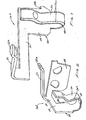
- the invention is embodied in an electrical connector, generally designated 10, for receiving an electrical plug (not shown).
- the connector includes a dielectric housing, generally designated 12, which may be a one-piece structure unitarily molded of plastic material or the like.
- Connector 10 is a receptacle connector, and housing 12 has a plug-insertion cavity 14 for receiving the electrical plug in an insertion direction indicated by arrow "A".
- plug-insertion cavity 14 for receiving the electrical plug in an insertion direction indicated by arrow "A".
- connector 10 also includes a second receptacle 16, with a pair of terminals, generally designated 18, associated with that receptacle.
- receptacle 16 may be provided for receiving a power electrical plug
- receptacle 14 may be provided for receiving an audio or signal plug.
- Connector 10 and housing 12 are adapted for mounting on a printed circuit board.
- the housing includes a board-mounting face 20.
- Terminals 18 include tail portions 22 exposed exteriorly of the housing, with contact ends 24 of the tail portions adapted for engaging circuit traces, such as power circuits, on the printed circuit board.
- the invention herein is centered around plug-insertion cavity 14 and a plurality of terminals mounted on housing 12 spaced longitudinally of the cavity. Specifically, five terminals are shown mounted on housing 12 longitudinally along opposite sides of cavity 14.
- the terminals are generally designated 26A-26E looking front-to-rear in FIG. 1, with front face 28 of connector housing 12 being the mating face of the connector.
- FIGS. 4-8 show the details of terminals 26A-26E, respectively.
- the terminals are substantially identical except for the length of the link arms which join the tail portions to the contact sections of the terminals, as described hereinafter. Therefore, like reference numerals have been applied in FIGS. 4-8 corresponding to like components of the respective terminals.
- third terminal 26C is shown in FIG. 6 to include a contact section, generally designated 28, at one end of a link arm 30 which joins the contact section to a tail portion 32 at the opposite end of the link arm.
- the tail portion includes a raised distal end 32a for engaging an appropriate circuit trace on the printed circuit board, as tail portion 32 is exposed exteriorly of housing 12 as seen in FIG. 1.
- each terminal is generally U-shaped to form a pair of legs, with one leg defining a mounting body portion 34 of the terminal and the other leg defining a spring contact arm 36 of the terminal.
- the terminal is stamped and formed of conductive sheet metal material, and body portion 34 is generally planar.
- the body portion includes a fixing tooth 34a for skiving into the plastic material of housing 12.
- the housing includes a plurality of mounting slots 38 (Fig. 1) for receiving body portions 34 of the terminals in mounting directions generally transversely of insertion direction "A". When the body portions are inserted into the mounting slots, fixing teeth 34a bite into the plastic material of the housing to secure or fix the terminal in position on the housing.
- Spring contact arm 36 of the U-shaped contact section 28 of each terminal extends upwardly from a bight portion 40 of the contact section which joins the spring contact arm to body portion 34.
- the spring contact arm has a contact portion 42 which is in the form of a convex "bump" to present a rounded contact surface for engaging the electrical plug.
- spring contact arm 36 extends generally transversely of insertion direction "A" (Fig. 1) whereby contact portion 42 is yieldably movable in the direction of arrow "B" (Fig. 6) generally perpendicular to the insertion direction. Still further, spring contact arm 36 is bowed outwardly toward body portion 34.
- the spring contact arm effectively is bowed outwardly of plug-insertion cavity 14 (Fig. 1) near the periphery thereof, whereby only contact portion 42 is exposed in the cavity.
- the front and rear edges 36a of spring contact arm 36 are chamfered to further prevent the inserted electrical plug from damaging the terminal, particularly from deforming the spring contact arm.
- terminals 26A, 26B, 26D and 26E shown in FIGS. 4, 5, 7 and 8, respectively are substantially identical except for the length of link arm 30 and the side of body portion 34 from which the link arm extends.
- the structure and function of U-shaped contact sections 28 in all of the terminals are identical.
- FIG. 8 One exception in the similarity of terminal construction is shown in FIG. 8, wherein the fifth terminal 26E has a plate 44 which extends inwardly from link arm 30 outside tail portion 32. This plate simply is formed as a shield to close the rear end of plug-insertion cavity 14 and prevent any foreign objects from being inserted thereinto.
- each spring contact arm 36 essentially is the only portions of the terminals which are exposed within cavity 14.
- a substantial portion of each spring contact arm 36 is disposed outside the cavity so that the spring contact arm cannot be engaged by the inserted electrical plug.
- the majority of each spring contact arm is outwardly removed from the cavity due to the outwardly bowed configuration of the arm as described above and clearly shown in FIGS. 4-8.
- the small portion of the spring contact arm around contact portion 42 is at the most flexible area of the arm and is further protected by the chamfered edges 36A of the arms.
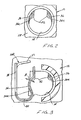
- FIG. 3 shows terminal 26A somewhat schematically in its mounted position within housing 12.
- the outwardly bowed configuration of spring contact arm 36 is clearly visible in relation to the periphery of plug-insertion cavity 14.
- this end elevational view of the terminal it can be understood that, with only body portion 34 of the terminal being fixed in the housing, considerable flexibility is provided through bight portion 40 and spring contact arm 36 of the terminal to give considerable flexibility to contact portion 42 in the direction of double-headed arrow "B" generally perpendicular to insertion direction "A" (Fig. 1) of the electrical plug.
- the terminal configuration is compact and does not extend into cavity 14 due to the outwardly bowed configuration of the spring contact arm, thereby greatly reducing the possibility of damaging the terminal by the insertion of foreign objects into the cavity.
Claims (16)
- Elektrischer Verbinder (10) zur Aufnahme eines elektrischen Steckers, umfassend:ein dielektrisches Gehäuse (12) mit einer Steckereinfügungskammer (14) zur Aufnahme des elektrischen Steckers in einer Einfügungsrichtung (A); undzumindest einen leitfähigen Anschlusskontakt (26A - 26E), der an dem Gehäuse montiert ist und umfasst:einen Rumpfabschnitt (34) zum Befestigen des Anschlusskontakts an dem Gehäuse,einen Federkontaktarm (36), der sich von dem Rumpfabschnitt aus zu der Steckereinfügungskammer hin erstreckt,wobei ein Kontaktabschnitt (42) des Federkontaktarms in der Kammer freiliegt, um an dem elektrischen Stecker in Anlage zu kommen,wobei der Federkontaktarm (36) sich generell quer zu der Einfügungsrichtung (A) erstreckt, wodurch der Kontaktabschnitt (42) generell senkrecht (B) zu der Einfügungsrichtung elastisch beweglich ist,dadurch gekennzeichnet, dassder Federkontaktarm (36) in der Nähe des Randes der Steckereinfügungskammer (14) aus dieser nach außen gebogen ist, wodurch nur der Kontaktabschnitt (42) in der Kammer freiliegt.
- Elektrischer Verbinder nach Anspruch 1, bei welchem der Kontaktabschnitt (42) des Anschlusskontakts konvex ist, sodass er eine gerundete Kontaktoberfläche präsentiert, die in der Kammer (14) zur Anlage an dem elektrischen Stecker freiliegt.
- Elektrischer Verbinder nach Anspruch 1, bei welchem das Gehäuse (12) einen Montageschlitz (38) zur Aufnahme des Rumpfabschnitts (34) des Anschlusskontakts in einer Richtung generell quer zu der Einfügungsrichtung umfasst.
- Elektrischer Verbinder nach Anspruch 1, bei welchem die Steckereinfügungskammer (14) länglich ist und eine Mehrzahl der Anschlusskontakte (26A - 26E) umfasst, die in Längsrichtung der Kammer im Abstand zueinander angeordnet sind.
- Elektrischer Verbinder nach Anspruch 1, bei welchem der Anschlusskontakt (26A - 26E) aus leitfähigem Metallblechmaterial gestanzt und geformt ist und der Rumpfabschnitt (34) des Anschlusskontakts allgemein eben ist.
- Elektrischer Verbinder nach Anspruch 1, bei welchem der Anschlusskontakt (26A - 26E) aus leitfähigem Metallblechmaterial gestanzt und geformt ist und der Federkontaktarm (36) einen vorderen und einen hinteren Rand (36a) aufweist, die in der Einfügungsrichtung voneinander beabstandet sind, wobei die Ränder abgeschrägt sind.
- Elektrischer Verbinder nach Anspruch 1, bei welchem der Anschlusskontakt (26A-26E) einen Anschlussendabschnitt (32) umfasst, der sich außerhalb des Gehäuses erstreckt.
- Elektrischer Verbinder nach Anspruch 1, bei welchem ein Kontaktabschnitt (28) des Anschlusskontakts (26A - 26E) allgemein U-förmig ist, sodass ein Paar Schenkel gebildet sind, wobei einer der Schenkel den Rumpfabschnitt (34) bestimmt und der andere der Schenkel den Federkontaktarm (36) bestimmt.
- Elektrischer Verbinder (10) zur Aufnahme eines elektrischen Steckers, umfassend:ein dielektrisches Gehäuse (12) mit einer länglichen Steckereinfügungskammer (14) zur Aufnahme des elektrischen Steckers in einer Einfügungsrichtung (A); undeine Mehrzahl von leitfähigen Anschlusskontakten (26A - 26E), die an dem Gehäuse in Längsrichtung der Kammer zueinander beabstandet montiert sind, wobei die leitfähigen Anschlusskontakte umfassen:dadurch gekennzeichnet, dasseinen allgemein U-förmigen Kontaktabschnitt (28) der ein Paar Schenkel bildet,einen Anschlussendabschnitt (32), der sich außerhalb des Gehäuses (12) erstreckt,wobei einer der Schenkel (34) einen Rumpfabschnitt zum Befestigen des Anschlusskontakts an dem Gehäuse (12) bestimmt und der andere der Schenkel (36) einen Federkontaktarm bestimmt, der sich von dem Basisabschnitt aus zu der Steckereinfügungskammer hin erstreckt, undwobei ein konvexer Kontaktabschnitt (42) des Federkontaktarms in der Kammer freiliegt, sodass er eine gerundete Kontaktoberfläche zur Anlage an dem elektrischen Stecker präsentiert,wobei der Federkontaktarm (36) sich allgemein quer zu der Einfügungsrichtung (A) erstreckt, wodurch der Kontaktabschnitt (42) allgemein senkrecht (B) zu der Einfügungsrichtung elastisch beweglich ist,
der Federkontaktarm (36) in der Nähe des Randes der Steckereinfügungskammer (14) aus dieser nach außen gebogen ist, wodurch nur der Kontaktabschnitt (42) in der Kammer freiliegt. - Elektrischer Verbinder nach Anspruch 9, bei welchem das Gehäuse (12) einen Montageschlitz (38) zur Aufnahme des Rumpfabschnitts (34) des Anschlusskontakts_in einer Richtung generel1 quer zu der Einfügungsrichtung umfasst.
- Elektrischer Verbinder nach Anspruch 9, bei welchem der Anschlusskontakt (26A - 26E) aus leitfähigem Metallblechmaterial gestanzt und geformt ist und der Rumpfabschnitt (34) des Anschlusskontakts allgemein eben ist.
- Elektrischer Verbinder nach Anspruch 9, bei welchem der Anschlusskontakt (26A - 26E) aus leitfähigem Metallblechmaterial gestanzt und geformt ist und der Federkontaktarm (36) einen vorderen und einen hinteren Rand (36a) aufweist, die in der Einfügungsrichtung voneinander beabstandet sind, wobei die Ränder abgeschrägt sind.
- Elektrischer Verbinder (10) zur Aufnahme eines elektrischen Steckers, umfassend:ein dielektrisches Gehäuse (12) mit einer Montagefläche (20), die zur Montage des Verbinders auf einer gedruckten Schaltungsplatine ausgelegt ist, wobei das Gehäuse eine längliche Steckereinfügungskammer (14) zur Aufnahme des elektrischen Steckers in einer Einfügungsrichtung (A) umfasst; undeine Mehrzahl von leitfähigen Anschlusskontakten (26A - 26E), die an dem Gehäuse in Längsrichtung der Kammer zueinander beabstandet montiert sind, wobei die leitfähigen Anschlusskontakte umfassen:dadurch gekennzeichnet, dasseinen Anschlussendabschnitt (32), der sich außerhalb des Gehäuses (12) erstreckt und zur Anlage an einer geeigneten Leiterbahn auf der gedruckten Schaltungsplatine ausgelegt ist,einen allgemein U-förmigen Kontaktabschnitt (28), der ein Paar Schenkel bildet,wobei einer der Schenkel (34) einen Rumpfabschnitt zur Befestigung des Anschlusskontaktes an dem Gehäuse (12) bestimmt, der andere der Schenkel (36) einen Federkontaktarm bestimmt, der sich von dem Basisabschnitt zu der Steckereinfügungskammer hin erstreckt, undein konvexer Kontaktabschnitt (42) des Federkontaktarms in der Kammer freiliegt, sodass er eine gerundete Kontaktoberfläche zur Anlage an dem elektrischen Stecker präsentiert,wobei der Federkontaktarm (36) sich allgemein quer zu der Einfügungsrichtung (A) erstreckt, wodurch der Kontaktabschnitt (42) allgemein senkrecht (B) zu der Einfügungsrichtung elastisch beweglich ist,
der Federkontaktarm (26) in der Nähe des Randes der Steckereinfügungskammer (14) aus dieser nach außen gebogen ist, wodurch nur der Kontaktabschnitt (42) in der Kammer freiliegt. - Elektrischer Verbinder nach Anspruch 13, bei welchem das Gehäuse (12) einen Montageschlitz (38) zur Aufnahme des Rumpfabschnitts (34) des Anschlusskontakts in einer Richtung generell quer zu der Einfügungsrichtung umfasst.
- Elektrischer Verbinder nach Anspruch 13, bei welchem der Anschlusskontakt (26A - 26E) aus leitfähigem Metallblechmaterial gestanzt und geformt ist und der Rumpfabschnitt (34) des Anschlusskontakts allgemein eben ist.
- Elektrischer Verbinder nach Anspruch 13, bei welchem der Anschlusskontakt (26A - 26E) aus leitfähigem Metallblechmaterial gestanzt und geformt ist und der Federkontaktarm (36) einen vorderen und einen hinteren Rand (36a) aufweist, die in der Einfügungsrichtung voneinander beabstandet sind, wobei die Ränder abgeschrägt sind.
Applications Claiming Priority (2)
| Application Number | Priority Date | Filing Date | Title |
|---|---|---|---|
| US09/901,285 US6478594B1 (en) | 2001-07-09 | 2001-07-09 | Electrical connector for receiving electrical plug |
| US901285 | 2001-07-09 |
Publications (3)
| Publication Number | Publication Date |
|---|---|
| EP1276181A2 EP1276181A2 (de) | 2003-01-15 |
| EP1276181A3 EP1276181A3 (de) | 2003-08-20 |
| EP1276181B1 true EP1276181B1 (de) | 2007-11-07 |
Family
ID=25413870
Family Applications (1)
| Application Number | Title | Priority Date | Filing Date |
|---|---|---|---|
| EP02014775A Expired - Fee Related EP1276181B1 (de) | 2001-07-09 | 2002-07-04 | Elektrischer Verbinder zum Aufnahme eines Steckers |
Country Status (4)
| Country | Link |
|---|---|
| US (1) | US6478594B1 (de) |
| EP (1) | EP1276181B1 (de) |
| CN (1) | CN1311587C (de) |
| DE (1) | DE60223319T2 (de) |
Families Citing this family (11)
| Publication number | Priority date | Publication date | Assignee | Title |
|---|---|---|---|---|
| TW540862U (en) * | 2002-05-24 | 2003-07-01 | Molex Inc | Battery connector |
| US7101230B2 (en) * | 2003-03-21 | 2006-09-05 | Molex Incorporated | Combined connector |
| US20050177199A1 (en) * | 2004-02-09 | 2005-08-11 | Cardiac Pacemakers, Inc. | PSA cable and connector for quadripolar lead terminal |
| US7753696B2 (en) * | 2005-05-12 | 2010-07-13 | Cardiac Pacemakers, Inc. | Lead terminal multi-tool |
| CN2909611Y (zh) * | 2006-03-17 | 2007-06-06 | 富士康(昆山)电脑接插件有限公司 | 插座连接器 |
| TWM300910U (en) * | 2006-06-02 | 2006-11-11 | Advanced Connectek Inc | Socket connector |
| CN200959398Y (zh) * | 2006-08-29 | 2007-10-10 | 富士康(昆山)电脑接插件有限公司 | 电连接器 |
| CN201285958Y (zh) * | 2008-08-27 | 2009-08-05 | 富士康(昆山)电脑接插件有限公司 | 插座连接器 |
| US9461416B2 (en) * | 2013-03-13 | 2016-10-04 | Roche Diabetes Care, Inc. | Low force electrical contact on metalized deformable substrates |
| CN107683553B (zh) * | 2016-04-15 | 2019-08-02 | 松下知识产权经营株式会社 | 插口装置 |
| US11196190B2 (en) | 2018-10-25 | 2021-12-07 | Hubbell Incorporated | Electrical connector |
Family Cites Families (24)
| Publication number | Priority date | Publication date | Assignee | Title |
|---|---|---|---|---|
| US4165147A (en) * | 1978-06-05 | 1979-08-21 | Magnetic Controls Company | Printed circuit board jack |
| US4392708A (en) | 1980-08-04 | 1983-07-12 | Switchcraft, Inc. | Electrical jack |
| US4598970A (en) * | 1983-03-10 | 1986-07-08 | Hosiden Electronics Co., Ltd. | Internally split type jack |
| US4548447A (en) | 1984-04-05 | 1985-10-22 | Magnetic Controls Company | Electrical jack |
| US4655535A (en) | 1985-06-03 | 1987-04-07 | Switchcraft, Inc. | Jack module and jackfield |
| US4820200A (en) | 1987-02-13 | 1989-04-11 | Switchcraft, Inc. | Slab-like jack module |
| JPH02131278U (de) | 1989-04-03 | 1990-10-31 | ||
| JPH0541514Y2 (de) | 1989-10-17 | 1993-10-20 | ||
| US5277628A (en) | 1992-08-27 | 1994-01-11 | Pan-International Industrial Corp. | Auditory jack |
| US5266042A (en) | 1992-08-31 | 1993-11-30 | Eastern Research, Inc. | Electrical jack and patch plug assembly |
| US5338215A (en) | 1993-03-19 | 1994-08-16 | Molex Incorporated | Jack assembly including a contact switching system |
| US5823796A (en) | 1996-04-02 | 1998-10-20 | Itt Manufacturing Enterprises, Inc. | Audio/power jack for IC card |
| JP3232240B2 (ja) * | 1996-04-26 | 2001-11-26 | ヒロセ電機株式会社 | 電気コネクタ |
| GB2314464B (en) | 1996-06-17 | 2000-04-19 | Cliff Electronics Components L | A stackable electrical socket |
| JP3266518B2 (ja) | 1996-08-28 | 2002-03-18 | エスエムケイ株式会社 | プラグとジャックの接続構造 |
| TW430192U (en) | 1998-06-25 | 2001-04-11 | Hon Hai Prec Ind Co Ltd | Connector with a receiving hole |
| TW415673U (en) * | 1998-10-17 | 2000-12-11 | Hon Hai Prec Ind Co Ltd | Electronic connector |
| TW398680U (en) * | 1998-12-22 | 2000-07-11 | Hon Hai Prec Ind Co Ltd | Electrical connector |
| US6126465A (en) | 1999-01-25 | 2000-10-03 | Franks, Jr.; George J. | Electrical connector system having dual purpose jack |
| US6062885A (en) * | 1999-04-23 | 2000-05-16 | Molex Incorporated | Electrical switch assembly |
| TW453528U (en) | 1999-07-02 | 2001-09-01 | Hon Hai Prec Ind Co Ltd | Socket connector |
| TW427559U (en) | 1999-07-06 | 2001-03-21 | Hon Hai Prec Ind Co Ltd | Speech socket electrical connector |
| TW444948U (en) * | 2000-05-25 | 2001-07-01 | Hon Hai Prec Ind Co Ltd | Receptacle connector |
| US6312274B1 (en) * | 2001-01-12 | 2001-11-06 | Advanced Connectek Inc. | Electrical connector |
-
2001
- 2001-07-09 US US09/901,285 patent/US6478594B1/en not_active Expired - Fee Related
-
2002
- 2002-07-04 DE DE60223319T patent/DE60223319T2/de not_active Expired - Fee Related
- 2002-07-04 EP EP02014775A patent/EP1276181B1/de not_active Expired - Fee Related
- 2002-07-08 CN CNB021286159A patent/CN1311587C/zh not_active Expired - Fee Related
Also Published As
| Publication number | Publication date |
|---|---|
| EP1276181A3 (de) | 2003-08-20 |
| DE60223319T2 (de) | 2008-08-28 |
| CN1396679A (zh) | 2003-02-12 |
| DE60223319D1 (de) | 2007-12-20 |
| EP1276181A2 (de) | 2003-01-15 |
| CN1311587C (zh) | 2007-04-18 |
| US6478594B1 (en) | 2002-11-12 |
Similar Documents
| Publication | Publication Date | Title |
|---|---|---|
| US10756466B2 (en) | Connector | |
| US7179126B2 (en) | Electrical connector with improved terminals | |
| US6394823B1 (en) | Connector with terminals having increased capacitance | |
| US5310360A (en) | Circuit board mounted modular phone jack | |
| US5885090A (en) | Electrical connector with stabilized offset spring arm | |
| US5453028A (en) | Electrical connector | |
| US20040259421A1 (en) | Cable connector assembly having improved shield members | |
| WO2006026036A1 (en) | Flat circuit connector | |
| JP3035814B2 (ja) | 表面係合式電気コネクタ | |
| EP0779684A2 (de) | Flachprofil-oberflächenmontierbare elektrische Verbinderanordnung | |
| EP1276181B1 (de) | Elektrischer Verbinder zum Aufnahme eines Steckers | |
| EP0632549B1 (de) | Elektrische Verbinderanordnung | |
| US6361332B1 (en) | Retention system for electrical connectors | |
| WO2005107022A1 (en) | : board mounted electrical connector assembly | |
| US6568963B2 (en) | Electrical connector assembly with improved contacts | |
| EP1315252B1 (de) | Elektrischer Verbinder mit verbessertem System für elektrostatische Entladung | |
| US6224409B1 (en) | Audio jack | |
| EP1380073B1 (de) | Elektrischer steckverbinder zum verbinden von flachen flexiblen schaltungen mit diskreten anschlusstiften | |
| US6186833B1 (en) | Hybrid connector with audio jack | |
| GB2406229A (en) | Memory card connector with side mounting locking means | |
| US20060258219A1 (en) | Electrical connector | |
| US6663444B2 (en) | Electrical connector with highly compliant terminals | |
| US6146172A (en) | Electrical connector | |
| US6793538B2 (en) | Slim modular jack | |
| EP0510264A1 (de) | Verbinderanordnung für Koaxialkabel |
Legal Events
| Date | Code | Title | Description |
|---|---|---|---|
| PUAI | Public reference made under article 153(3) epc to a published international application that has entered the european phase |
Free format text: ORIGINAL CODE: 0009012 |
|
| AK | Designated contracting states |
Kind code of ref document: A2 Designated state(s): AT BE BG CH CY CZ DE DK EE ES FI FR GB GR IE IT LI LU MC NL PT SE SK TR |
|
| AX | Request for extension of the european patent |
Free format text: AL;LT;LV;MK;RO;SI |
|
| PUAL | Search report despatched |
Free format text: ORIGINAL CODE: 0009013 |
|
| RIN1 | Information on inventor provided before grant (corrected) |
Inventor name: O'SULLIVAN, DAMIEN Inventor name: HANNON, DAVE Inventor name: CURTIN, PETER THOMAS |
|
| AK | Designated contracting states |
Designated state(s): AT BE BG CH CY CZ DE DK EE ES FI FR GB GR IE IT LI LU MC NL PT SE SK TR |
|
| AX | Request for extension of the european patent |
Extension state: AL LT LV MK RO SI |
|
| 17P | Request for examination filed |
Effective date: 20040214 |
|
| AKX | Designation fees paid |
Designated state(s): DE FR GB |
|
| GRAP | Despatch of communication of intention to grant a patent |
Free format text: ORIGINAL CODE: EPIDOSNIGR1 |
|
| GRAS | Grant fee paid |
Free format text: ORIGINAL CODE: EPIDOSNIGR3 |
|
| GRAA | (expected) grant |
Free format text: ORIGINAL CODE: 0009210 |
|
| AK | Designated contracting states |
Kind code of ref document: B1 Designated state(s): DE FR GB |
|
| REG | Reference to a national code |
Ref country code: GB Ref legal event code: FG4D |
|
| REF | Corresponds to: |
Ref document number: 60223319 Country of ref document: DE Date of ref document: 20071220 Kind code of ref document: P |
|
| ET | Fr: translation filed | ||
| PLBE | No opposition filed within time limit |
Free format text: ORIGINAL CODE: 0009261 |
|
| STAA | Information on the status of an ep patent application or granted ep patent |
Free format text: STATUS: NO OPPOSITION FILED WITHIN TIME LIMIT |
|
| 26N | No opposition filed |
Effective date: 20080808 |
|
| PGFP | Annual fee paid to national office [announced via postgrant information from national office to epo] |
Ref country code: DE Payment date: 20080829 Year of fee payment: 7 |
|
| PGFP | Annual fee paid to national office [announced via postgrant information from national office to epo] |
Ref country code: FR Payment date: 20080729 Year of fee payment: 7 |
|
| PGFP | Annual fee paid to national office [announced via postgrant information from national office to epo] |
Ref country code: GB Payment date: 20080729 Year of fee payment: 7 |
|
| GBPC | Gb: european patent ceased through non-payment of renewal fee |
Effective date: 20090704 |
|
| REG | Reference to a national code |
Ref country code: FR Ref legal event code: ST Effective date: 20100331 |
|
| PG25 | Lapsed in a contracting state [announced via postgrant information from national office to epo] |
Ref country code: FR Free format text: LAPSE BECAUSE OF NON-PAYMENT OF DUE FEES Effective date: 20090731 |
|
| PG25 | Lapsed in a contracting state [announced via postgrant information from national office to epo] |
Ref country code: GB Free format text: LAPSE BECAUSE OF NON-PAYMENT OF DUE FEES Effective date: 20090704 |
|
| PG25 | Lapsed in a contracting state [announced via postgrant information from national office to epo] |
Ref country code: DE Free format text: LAPSE BECAUSE OF NON-PAYMENT OF DUE FEES Effective date: 20100202 |