EP1275973A2 - Supraleitender Magnet für die magnetische Resonanz mit offenem Aufbau und mit einem konischen Bildgebungsvolumen - Google Patents
Supraleitender Magnet für die magnetische Resonanz mit offenem Aufbau und mit einem konischen Bildgebungsvolumen Download PDFInfo
- Publication number
- EP1275973A2 EP1275973A2 EP02254785A EP02254785A EP1275973A2 EP 1275973 A2 EP1275973 A2 EP 1275973A2 EP 02254785 A EP02254785 A EP 02254785A EP 02254785 A EP02254785 A EP 02254785A EP 1275973 A2 EP1275973 A2 EP 1275973A2
- Authority
- EP
- European Patent Office
- Prior art keywords
- superconducting
- yoke
- imaging volume
- magnet
- patient support
- Prior art date
- Legal status (The legal status is an assumption and is not a legal conclusion. Google has not performed a legal analysis and makes no representation as to the accuracy of the status listed.)
- Withdrawn
Links
Images
Classifications
-
- G—PHYSICS
- G01—MEASURING; TESTING
- G01R—MEASURING ELECTRIC VARIABLES; MEASURING MAGNETIC VARIABLES
- G01R33/00—Arrangements or instruments for measuring magnetic variables
- G01R33/20—Arrangements or instruments for measuring magnetic variables involving magnetic resonance
- G01R33/28—Details of apparatus provided for in groups G01R33/44 - G01R33/64
- G01R33/38—Systems for generation, homogenisation or stabilisation of the main or gradient magnetic field
- G01R33/3808—Magnet assemblies for single-sided MR wherein the magnet assembly is located on one side of a subject only; Magnet assemblies for inside-out MR, e.g. for MR in a borehole or in a blood vessel, or magnet assemblies for fringe-field MR
-
- G—PHYSICS
- G01—MEASURING; TESTING
- G01R—MEASURING ELECTRIC VARIABLES; MEASURING MAGNETIC VARIABLES
- G01R33/00—Arrangements or instruments for measuring magnetic variables
- G01R33/20—Arrangements or instruments for measuring magnetic variables involving magnetic resonance
- G01R33/28—Details of apparatus provided for in groups G01R33/44 - G01R33/64
- G01R33/38—Systems for generation, homogenisation or stabilisation of the main or gradient magnetic field
- G01R33/381—Systems for generation, homogenisation or stabilisation of the main or gradient magnetic field using electromagnets
- G01R33/3815—Systems for generation, homogenisation or stabilisation of the main or gradient magnetic field using electromagnets with superconducting coils, e.g. power supply therefor
Definitions
- This invention relates to an open architecture superconducting magnet assembly for a magnetic resonance imaging system (hereinafter called "MRI"), and more particularly to a magnet assembly utilizing a conical or prism shaped imaging region and suitable for interventional surgical procedures.
- MRI magnetic resonance imaging system
- a superconducting magnet can be made superconducting by placing it in an extremely cold environment, such as by enclosing it in a cryostat or pressure vessel containing liquid helium or other cryogen.
- the extreme cold ensures that the magnet coils are superconducting, such that when a power source is initially connected to the magnet coils for a period (for example, of only ten minutes) to introduce a current flow through the coils, the current will continue to flow through the coils even after power is removed due to the absence of electrical resistance at the superconducting temperature, thereby maintaining a strong magnetic field.
- Superconducting magnets find wide application in the field of MRI.
- a problem encountered in the use of most MRI equipment is that they utilize solenoidal magnets enclosed in cylindrical structures with a central bore opening for patient access.
- the patient is practically enclosed in the warm central bore, which can induce claustrophobia in some patients.
- MRI interventional diagnostic or surgical procedures
- the desirability of an open architecture MRI magnet in which the patient is not essentially totally enclosed has thus long been recognized.
- an open architecture MRI magnet to provide open space about the patient poses a number of additional and unique technical problems and challenges.
- One problem is to provide a suitable superconducting structure which will provide the required magnetic field yet occupies much less space than conventional cylindrical MRI magnet structures, and yet which nevertheless can provide the required strong and homogeneous magnetic field imaging region or imaging volume.
- a typical MRI imaging region is a sphere 15 to 20 inches in diameter, or a cylindrical imaging volume 10 to 15 inches in diameter and 10 to 20 inches long.
- the use of symmetrical or mirror image magnetic components about the imaging volume with magnetic shaping and positionable shimming members have enabled the adjustment or fine tuning of the resultant magnetic field to provide a spherical or cylindrical volume imaging volume with the required magnetic homogeneity.
- a spherical or cylindrical imaging region or volume is not necessary.
- a smaller imaging or viewing region at the point where the surgical procedure or needle insertion begins on the surface of the body of the patient can readily utilize a smaller imaging volume which is not a spherical or cylindrical volume. It may even be desirable for such procedures to have the imaging volume increase as it penetrates into the body away from the point where the surgery begins, that is a generally conical imaging volume. Moreover, it is highly desirable and often necessary to provide a flexible design which facilitates construction while minimizing cost of the MRI equipment.
- an open architecture platform superconducting magnet suitable for interventional procedures includes shaped magnetic yoke and associated magnet coil.
- the yoke and coil are shaped to provide an imaging region in open space above the coil which is tapered, in that the cross section of the imaging volume decreases in the direction remote from the coil.
- the tapered imaging region is in the shape of a frustrum of a right cone or a prism.
- a patient support is positioned above the magnet coil and magnet coil axis.
- the magnetic field may have a monotonic gradient.
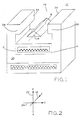
- superconducting magnet 10 includes a plurality of superconducting coils such as 12 in a helium vessel 14 to provide a magnetic field perpendicular to axis 18 between magnet poles 28 in the manner well known in the art.
- FIG. 2 illustrates the imaging axes X, Y and Z of superconducting magnet 10.
- X is vertical axis 22
- Y is horizontal axis 24
- Z is orthogonal axis 18 which extends into space 26 between opposed poles 28 of yoke assembly 30.
- Patient support 54 (shown in FIG. 4) extends parallel to axis Y or axis Z in space 48 between opposed magnet poles 28 such that the patient can lie along either axis depending on convenience or superconducting magnet 10 dimensions.
- yoke assembly 30 includes planar poles 28 and pole surfaces 34.
- magnet coils such as 12 may be wound to form a non-cylindrical coil in order to vary and control the current density or pattern of the current flow through the coils in order to achieve maximum homogeneity at minimum cost.
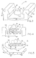
- imaging volume 38 for interventional procedures and surgery is a generally conical or frustrum of a cone shaped imaging volume. This is shown in FIG. 3.
- imaging volume is in the shape of a frustrum of a right cone.
- the imaging region would, of course, be invisible to the eye but for explanation purposes and illustration is shown as a solid volume (as are the imaging regions in the other Figures).
- opposed pole faces 44 are inclined pole faces.
- return magnetic yoke 30 includes lobes 46 on the sides of poles 28 remote or opposite from inclined pole faces 44.
- Lobes 46 and inclined pole face 44 may be utilized with the prism shaped imaging volume 16 of superconducting magnet 10 yoke assembly 30 shown in FIG. 1. These simple and versatile design variables are useful in shaping the taper of the imaging volume in the X direction 22, a taper which increases in cross section from the end adjacent opening 48 toward magnet coil 12 remote from the opening.
- inclined pole faces 144 are shaped or contoured, as is magnetic member 50 positioned at bottom 52 of yoke opening 48.
- the contouring may be provided in either or both of the Y 24 or Z 18 directions (see FIG. 2).
- Magnetic member 50 may be made of superconducting material such as NbTi (niobium titanium), or the contour or profile 51 may be approximated or provided by the wound wire 53 of magnet coil 12.
- Moveable patient support 54 is located just below imaging volume 16, which in this embodiment is a prism shaped volume.
- the axis of magnet coil 12, indicated generally as 49 (see FIG. 4), is below and parallel to patient support 54.
- Patient support 54 is moveable in the X22, Y24 and Z18 directions to position patient 56 (shown dotted) such that the region to be imaged, and/or surgery to be performed on, is properly positioned in imaging volume 16. It is noted that the tapered imaging volume is small or narrow at the upper region at the point where surgery begins or needle insertion begins and increases in cross section as the surgeon moves into the body of patient 56.
- coil windings 60 may be wound with varying thickness as depicted by contoured surface 64 and which is positioned below patient support 54 and patient 56.
- magnetic material such as iron may be used and shaped as member 62.
- Coil windings 60 also pass through saucer shaped magnetic yoke assembly 66 positioned below and separated from superconducting member 62.
- Yoke assembly 66 includes contoured surface 68 on the surface remote from contoured surface 64.
- the shaping of magnetic members 62 and 66 and the positioning of windings 60 are selected to control the current density or pattern, or both, of the imaging side and back side, respectively, of superconducting magnet 10, and provide a magnetic path 70 to optimize magnetic field homogeneity in the imaging volume.
- Tapered imagery volumes 16 and 38 do not have to be a true right cone or prism.
- An oblique or deformed cone or prism is suitable for many interventional procedures.
- the imaging volumes may be "generally applied” that is they generally increase in cross section in the direction inward toward yoke 30 from opening 48 between pole pieces 28 (see FIGs. 1 and 3).
- highly uniform magnetic field homogeneity in imaging volumes 16 and 38 may not be required for certain interventional procedures such that a monotonic field gradient, or gradient in which 5MT/M (five Milli-Tesla per meter), may be acceptable.
- a montonic magnetic field gradient is one in which the magnetic field steadily changes or increased without regions of decrease. The increase, may, for example, be a linear function.
- Superconducting magnet 10 may be aptly termed a platform magnet in that the magnet forms a platform below patient 56 with tapered imaging volume 16, 38 extending above the patient support 54. This provides substantial open space unencumbered with spacers and supports which are required and extend between the double poleface open architecture MRI designs.
- the generation and utilization of a generally tapered imaging volume in a platform superconducting magnet instead of a spherical or cylindrical imaging volume enables considerable design flexibility in the positioning, shaping and contouring of the magnetic members of the magnet and shaping of the current density or pattern to provide an optimized tapered imaging volume homogeneity at minimized cost.
Landscapes
- Physics & Mathematics (AREA)
- Health & Medical Sciences (AREA)
- Life Sciences & Earth Sciences (AREA)
- General Health & Medical Sciences (AREA)
- General Life Sciences & Earth Sciences (AREA)
- Vascular Medicine (AREA)
- Condensed Matter Physics & Semiconductors (AREA)
- General Physics & Mathematics (AREA)
- Magnetic Resonance Imaging Apparatus (AREA)
Applications Claiming Priority (2)
| Application Number | Priority Date | Filing Date | Title |
|---|---|---|---|
| US09/902,364 US6462548B1 (en) | 2001-07-09 | 2001-07-09 | Open architecture magnetic reasonance superconducting platform magnet conical imaging |
| US902364 | 2001-07-09 |
Publications (2)
| Publication Number | Publication Date |
|---|---|
| EP1275973A2 true EP1275973A2 (de) | 2003-01-15 |
| EP1275973A3 EP1275973A3 (de) | 2004-07-21 |
Family
ID=25415761
Family Applications (1)
| Application Number | Title | Priority Date | Filing Date |
|---|---|---|---|
| EP02254785A Withdrawn EP1275973A3 (de) | 2001-07-09 | 2002-07-09 | Supraleitender Magnet für die magnetische Resonanz mit offenem Aufbau und mit einem konischen Bildgebungsvolumen |
Country Status (3)
| Country | Link |
|---|---|
| US (1) | US6462548B1 (de) |
| EP (1) | EP1275973A3 (de) |
| JP (1) | JP4017460B2 (de) |
Families Citing this family (9)
| Publication number | Priority date | Publication date | Assignee | Title |
|---|---|---|---|---|
| AU2003269469A1 (en) * | 2002-10-21 | 2004-05-04 | Bbms Ltd. | Method and apparatus for magnetic resonance analysis |
| JP4685456B2 (ja) * | 2005-01-11 | 2011-05-18 | 株式会社日立メディコ | 磁気共鳴イメージング装置 |
| US7274192B2 (en) * | 2005-05-31 | 2007-09-25 | General Electric Company | Combined open and closed magnet configuration for MRI |
| GB2448479B (en) * | 2007-04-18 | 2009-06-03 | Siemens Magnet Technology Ltd | Improved shim for imaging magnets |
| ITTO20070840A1 (it) * | 2007-11-23 | 2009-05-24 | Paramed Medical Systems S R L | Sistema di posizionamento per un'apparecchiatura medicale, ed apparecchiatura di imaging a risonanza magnetica comprendente un tale sistema |
| JP4761483B2 (ja) * | 2009-03-10 | 2011-08-31 | 株式会社東栄科学産業 | 電磁石、磁場印加装置および磁場印加システム |
| WO2013148310A1 (en) * | 2012-03-28 | 2013-10-03 | Hologic, Inc. | Mri scanner |
| US10470686B2 (en) | 2012-12-26 | 2019-11-12 | Koninklijke Philips N.V. | Accessible magnetic resonance imaging scanner system for magnetic resonance guided interventional procedures |
| CN110676009B (zh) * | 2019-10-18 | 2024-11-12 | 江苏力磁医疗设备有限公司 | 专科磁共振用倾斜开口磁体 |
Family Cites Families (14)
| Publication number | Priority date | Publication date | Assignee | Title |
|---|---|---|---|---|
| GB8500248D0 (en) * | 1985-01-04 | 1985-02-13 | Oxford Magnet Tech | Solenoids |
| US5134374A (en) * | 1989-06-01 | 1992-07-28 | Applied Superconetics | Magnetic field control apparatus |
| US5382904A (en) * | 1992-04-15 | 1995-01-17 | Houston Advanced Research Center | Structured coil electromagnets for magnetic resonance imaging and method for fabricating the same |
| JP3742662B2 (ja) * | 1992-08-05 | 2006-02-08 | ゼネラル・エレクトリック・カンパニイ | 開放形磁気共鳴イメージングに適した磁石 |
| US6335623B1 (en) * | 1992-12-18 | 2002-01-01 | Fonar Corporation | MRI apparatus |
| US5463364A (en) * | 1994-04-13 | 1995-10-31 | Bruker Analytische Messtechnik Gmbh | Magnet system for NMR tomography |
| US5675305A (en) * | 1996-07-17 | 1997-10-07 | Picker International, Inc. | Multiple driven C magnet |
| US5677630A (en) * | 1996-10-21 | 1997-10-14 | General Electric Company | Planar superconducting MRI magnet |
| US5801609A (en) * | 1997-04-25 | 1998-09-01 | General Electric Company | MRI head magnet |
| US6157278A (en) * | 1997-07-23 | 2000-12-05 | Odin Technologies Ltd. | Hybrid magnetic apparatus for use in medical applications |
| JP2001517510A (ja) * | 1997-09-25 | 2001-10-09 | オーディン・テクノロジーズ・リミテッド | Mriのための磁気装置 |
| US5977771A (en) * | 1997-11-03 | 1999-11-02 | Picker International, Inc. | Single gradient coil configuration for MRI systems with orthogonal directed magnetic fields |
| AU2438799A (en) * | 1998-02-09 | 1999-08-23 | Odin Medical Technologies Ltd | A method for designing open magnets and open magnetic apparatus for use in mri/mrt probes |
| US6265959B1 (en) * | 1998-04-29 | 2001-07-24 | New York University | Open unipolar magnetic structure |
-
2001
- 2001-07-09 US US09/902,364 patent/US6462548B1/en not_active Expired - Fee Related
-
2002
- 2002-07-09 JP JP2002199370A patent/JP4017460B2/ja not_active Expired - Fee Related
- 2002-07-09 EP EP02254785A patent/EP1275973A3/de not_active Withdrawn
Non-Patent Citations (1)
| Title |
|---|
| None * |
Also Published As
| Publication number | Publication date |
|---|---|
| JP2003093366A (ja) | 2003-04-02 |
| EP1275973A3 (de) | 2004-07-21 |
| JP4017460B2 (ja) | 2007-12-05 |
| US6462548B1 (en) | 2002-10-08 |
Similar Documents
| Publication | Publication Date | Title |
|---|---|---|
| JP3556948B2 (ja) | 磁気共鳴イメージング用の円錐台形磁石 | |
| EP1113287B1 (de) | Kopfspule für die bilderzeugende magnetische Resonanz | |
| US5023554A (en) | Fringe field MRI | |
| WO2018097863A1 (en) | A mirror assembly and radio frequency head coil for a magnetic resonance imaging system and methods thereof | |
| US5490509A (en) | Method and apparatus for MRI using selectively shaped image volume of homogeneous NMR polarizing field | |
| US8947090B2 (en) | Electromagnet assembly | |
| US6462548B1 (en) | Open architecture magnetic reasonance superconducting platform magnet conical imaging | |
| CN111913142A (zh) | 基本场磁体装置、磁共振断层造影系统和测量方法 | |
| CN115137344B (zh) | 具有不对称的场生成单元的磁共振成像设备 | |
| EP0620922B1 (de) | Lokale transversale gradientenspule für die bildgebende magnetische resonanz | |
| AU2019396124B2 (en) | Gradient coil system | |
| US5814993A (en) | Magnet arrangement for a diagnostic nuclear magnetic resonance apparatus | |
| EP1499237A1 (de) | Verfahren und vorrichtung zur magnetresonanzbildgebung und kathetersteuerung | |
| JP2007203032A (ja) | 磁気共鳴イメージング装置 | |
| US7898257B2 (en) | Open yoke magnet assembly | |
| US6504461B2 (en) | Open magnet with recessed field shaping coils | |
| EP4279939A1 (de) | Statischer feldmagnet und mrt-vorrichtung | |
| JP2000102518A (ja) | 磁気共鳴イメージング装置 | |
| US20070114997A1 (en) | Systems, methods and apparatus for a partially elongated field of view in a magnetic resonance imaging system | |
| US6100690A (en) | Radio frequency coil for magnetic resonance imaging apparatus | |
| KR100351072B1 (ko) | 자기공명영상장치용고주파코일 | |
| JP4142011B2 (ja) | 磁場生成組立体及び方法 | |
| CN221426850U (zh) | 匀场元件和磁共振成像装置 | |
| US20240230803A1 (en) | Static field magnet and mri apparatus | |
| US20230258752A1 (en) | Dedicated Magnetic Resonance Device |
Legal Events
| Date | Code | Title | Description |
|---|---|---|---|
| PUAI | Public reference made under article 153(3) epc to a published international application that has entered the european phase |
Free format text: ORIGINAL CODE: 0009012 |
|
| AK | Designated contracting states |
Kind code of ref document: A2 Designated state(s): AT BE BG CH CY CZ DE DK EE ES FI FR GB GR IE IT LI LU MC NL PT SE SK TR |
|
| AX | Request for extension of the european patent |
Free format text: AL;LT;LV;MK;RO;SI |
|
| PUAL | Search report despatched |
Free format text: ORIGINAL CODE: 0009013 |
|
| AK | Designated contracting states |
Kind code of ref document: A3 Designated state(s): AT BE BG CH CY CZ DE DK EE ES FI FR GB GR IE IT LI LU MC NL PT SE SK TR |
|
| AX | Request for extension of the european patent |
Extension state: AL LT LV MK RO SI |
|
| 17P | Request for examination filed |
Effective date: 20050121 |
|
| AKX | Designation fees paid |
Designated state(s): DE GB NL |
|
| 17Q | First examination report despatched |
Effective date: 20070118 |
|
| STAA | Information on the status of an ep patent application or granted ep patent |
Free format text: STATUS: THE APPLICATION IS DEEMED TO BE WITHDRAWN |
|
| 18D | Application deemed to be withdrawn |
Effective date: 20070201 |