EP1113287B1 - Kopfspule für die bilderzeugende magnetische Resonanz - Google Patents
Kopfspule für die bilderzeugende magnetische Resonanz Download PDFInfo
- Publication number
- EP1113287B1 EP1113287B1 EP00311615A EP00311615A EP1113287B1 EP 1113287 B1 EP1113287 B1 EP 1113287B1 EP 00311615 A EP00311615 A EP 00311615A EP 00311615 A EP00311615 A EP 00311615A EP 1113287 B1 EP1113287 B1 EP 1113287B1
- Authority
- EP
- European Patent Office
- Prior art keywords
- conductors
- coil
- circular
- head
- spaced
- Prior art date
- Legal status (The legal status is an assumption and is not a legal conclusion. Google has not performed a legal analysis and makes no representation as to the accuracy of the status listed.)
- Expired - Lifetime
Links
- 238000002595 magnetic resonance imaging Methods 0.000 title claims description 15
- 239000004020 conductor Substances 0.000 claims description 46
- 238000003384 imaging method Methods 0.000 description 19
- 210000004556 brain Anatomy 0.000 description 4
- 238000005481 NMR spectroscopy Methods 0.000 description 2
- 238000006073 displacement reaction Methods 0.000 description 2
- RYGMFSIKBFXOCR-UHFFFAOYSA-N Copper Chemical compound [Cu] RYGMFSIKBFXOCR-UHFFFAOYSA-N 0.000 description 1
- 239000004593 Epoxy Substances 0.000 description 1
- 230000002411 adverse Effects 0.000 description 1
- 210000003484 anatomy Anatomy 0.000 description 1
- 230000004323 axial length Effects 0.000 description 1
- 210000000133 brain stem Anatomy 0.000 description 1
- 210000001638 cerebellum Anatomy 0.000 description 1
- 210000003710 cerebral cortex Anatomy 0.000 description 1
- 239000002131 composite material Substances 0.000 description 1
- 229910052802 copper Inorganic materials 0.000 description 1
- 239000010949 copper Substances 0.000 description 1
- 229940079593 drug Drugs 0.000 description 1
- 239000003814 drug Substances 0.000 description 1
- 230000005284 excitation Effects 0.000 description 1
- 239000011152 fibreglass Substances 0.000 description 1
- 229910052734 helium Inorganic materials 0.000 description 1
- 239000001307 helium Substances 0.000 description 1
- SWQJXJOGLNCZEY-UHFFFAOYSA-N helium atom Chemical compound [He] SWQJXJOGLNCZEY-UHFFFAOYSA-N 0.000 description 1
- 239000007788 liquid Substances 0.000 description 1
- 238000001208 nuclear magnetic resonance pulse sequence Methods 0.000 description 1
- 230000002085 persistent effect Effects 0.000 description 1
- 239000004033 plastic Substances 0.000 description 1
- 239000000523 sample Substances 0.000 description 1
- 230000035945 sensitivity Effects 0.000 description 1
- 230000007704 transition Effects 0.000 description 1
Images
Classifications
-
- G—PHYSICS
- G01—MEASURING; TESTING
- G01R—MEASURING ELECTRIC VARIABLES; MEASURING MAGNETIC VARIABLES
- G01R33/00—Arrangements or instruments for measuring magnetic variables
- G01R33/20—Arrangements or instruments for measuring magnetic variables involving magnetic resonance
- G01R33/28—Details of apparatus provided for in groups G01R33/44 - G01R33/64
- G01R33/32—Excitation or detection systems, e.g. using radio frequency signals
- G01R33/34—Constructional details, e.g. resonators, specially adapted to MR
- G01R33/34046—Volume type coils, e.g. bird-cage coils; Quadrature bird-cage coils; Circularly polarised coils
- G01R33/34053—Solenoid coils; Toroidal coils
-
- G—PHYSICS
- G01—MEASURING; TESTING
- G01R—MEASURING ELECTRIC VARIABLES; MEASURING MAGNETIC VARIABLES
- G01R33/00—Arrangements or instruments for measuring magnetic variables
- G01R33/20—Arrangements or instruments for measuring magnetic variables involving magnetic resonance
- G01R33/28—Details of apparatus provided for in groups G01R33/44 - G01R33/64
- G01R33/32—Excitation or detection systems, e.g. using radio frequency signals
- G01R33/34—Constructional details, e.g. resonators, specially adapted to MR
- G01R33/34046—Volume type coils, e.g. bird-cage coils; Quadrature bird-cage coils; Circularly polarised coils
- G01R33/34076—Birdcage coils
Definitions
- This invention relates to a magnetic resonance imaging system (hereinafter called "MRI"), and more particularly to a short head coil apparatus for imaging the human head or brain.
- MRI magnetic resonance imaging system
- the main superconducting magnet coils are enclosed in a cylindrical cryogen pressure vessel, contained within a vacuum vessel and forming an imaging bore in the central region.
- the main magnet coils develop a strong magnetic field in the imaging bore.
- Typical field strengths of 0.5 to 1.5T (Tesla) require homogeneity of 10 parts per million (ppm) over volumes on the order of a 45cm diameter sphere.
- RF head coils are applied to generate a uniform RF magnetic field over the brain.
- these head coils are very long, and continue past the apex of the patient's head. Since the signal to noise ratio is proportional to the square root of the Quality factor of the loaded coil divided by the effective volume, which is a volume integral of the RF energy stored in the coil, it is important to limit the size of RF coils and keep them as small as possible while at the same time providing the necessary MRI signals. However, this has to be done while maintaining the RF magnetic field homogeneity of the coils for equal flip angle distribution during transmit pulses and equal sensitivity during receive.
- EP-A-0 758 092 discloses a radio frequency coil having a birdcage configuration for magnetic resonance imaging, the coil being arranged to be disposed closely adjacent to a patient's head.
- the coil includes a plurality of spaced conductors positioned parallel to and about an axis to form a substantially cylindrical shaped portion around the axis.
- Two circular conductors are provided, each of which supports an opposite end of the spaced conductors forming the cylindrical portion.
- the spaced conductors extend beyond one of the circular conductors and bend inwardly towards the axis to form a dome portion in the apex of which the spaced conductors converge to a virtual ground interconnection point.
- Coil number 1 covers the cerebellum, the brainstem and the lower part of the cerebral cortex.
- Coil number 2 which is shown having a dome shape images the top part of the brain and has a plurality of spaced conductors supported at their respective opposite ends by two circular conductors of different diameter.
- US-A-5 453 692 discloses an RF probe for an MRI device including a plurality of hollow cylindrical resonators having a birdcage configuration arranged in series such that the respective axes of the resonators align substantially in a z-axis direction of a three dimensional orthogonal co-ordinate system. Adjacent ends of the resonators may be arranged to overlap to couple them together.
- the resonators form a first cylindrical portion followed by a tapered portion in the shape of the frustum of a cone which in turn is followed by a second cylindrical portion which, for one of the resonators, has a smaller diameter than the first cylindrical portion.
- the present invention is defined in claim 1.
- An asymmetrical coil assembly may surround the first cylinder and extend to the tapered portion of the conductors.
- the coil in the central region of the asymmetrical coil assembly is of a larger diameter than the end coils of the coil assembly.
- the resultant improved homogeneity in the magnetic field provides improved quality imaging.
- the head coil may be pulsed by the transmit coil of the magnetic resonance imager or alternatively may act as a receiver coil for transmit pulses from the transmit coil surrounding the interior of the bore of the superconducting magnet.
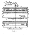
- MRI superconducting magnet assembly 10 includes cryogen pressure vessel 11 positioned concentrically within vacuum vessel 21 and forming central imaging bore 12 about axis 5. Positioned within pressure vessel 11 is composite drum 4 with axially spaced main magnet coils 16 wound in axial slots on the drum. Correction coils 17, 18 and 19 within pressure vessel 11 enable shimming of the magnetic field in bore 12 to improve magnetic field homogeneity to acceptable limits. Supports 32 secure superconducting magnet assembly 10 on floor 34.
- lead assembly 26 which includes connector 25 outside vacuum vessel 23 and conduit 20 passing through plate 27 for electrical connection of mechanical leads or wires to the components including magnet coils 16, 17, 18, 19 and 21 within cryogen pressure vessel 11.
- patient support 38 Positioned within bore 12 of superconducting magnet 10 is patient support 38 which is moveable within the bore as indicated by arrows 7 and 9.
- a head coil 46 is positioned at one end of patient support 38 on mounting member 47 secured to the patient support.
- a patient (not shown) lying on patient support 44 would be positioned with the patient's head being imaged within head coil 46.
- Head coil 46 is described in detail below.
- RF assembly 40, 41, 42 Surrounding the central bore of vacuum vessel 21 is RF assembly 40, 41, 42 including gradient coil 40 and transmit coil 42 separated by RF shield 41.
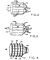
- head coil 46 includes a so-called birdcage configuration of conductors which would be encased or embedded in a suitable fiberglass epoxy plastic housing, a portion of which is shown in FIG. 2 .
- a plurality of axially extending parallel conductors or rods 52 form a cylindrical portion 54 supported at the ends by circular end ring conductors 56 and 58.
- Conductors 52, 56 and 58 are copper and in one application are strips 1/2 inch (1.27 cm) wide. The diameter of circular conductors 56 and 58 is 23 centimeters.
- Axial conductors 52 extend beyond circular end conductor 58 at a 45° angle towards axis 51. Angular portions 50 of conductors 52 do not meet at axis 51 or at any point, but rather the conductors terminate at reduced size circular conductor 53 forming an opening with a diameter of 10 centimeters, and tapered portion 55 in the shape of the frustum of a circular cone. The patients head would be positioned through circular end ring 56 into cylindrical portion 54 while imaging.
- the number of rods 52 may vary and may, by way of example, be eight or more rods equally angularly spaced about axis 51.
- end ring 53 is too close to the head of the patient being imaged, it has been found that high spots (high B1 amplitude) will occur where the end ring is close to the tissue of the patient.
- the birdcage configurations of the subject invention prevents such high spots and thus provides improved magnetic field homogeneity and imaging quality.
- the axial length of second cylinder portion 157 is chosen such that the resulting apex image is uniform, and in one application is 3.5 centimeters long axially.
- birdcage 146 can be driven in the linear mode to generate the B1 magnetic field in the X or horizontal direction.
- End ring 153 prevents axial conductors 152 meeting at a point which it has been found also provides magnetic field high spots which would detract from imaging quality.
- the displacement of end ring 153 away from the patient's head in cylindrical portion 154 results in improved homogeneity with the axial displacement being selected to provide a uniform apex image.
- FIG. 4 shows an asymmetric solenoid coil assembly 160 applied around birdcage 146 to generate the B1 magnetic field component in the Z direction.
- Center coil 162 of coil assembly 160 has a slightly bigger radius than the other turns or loops 164 to maintain uniformity close to the conductors.
- the last coil 166 over the tapered end of birdcage 146 has a smaller diameter than the others, such that coil assembly 160 can be truncated and kept short while maintaining homogeneity equal to a much longer solenoid.
- Coils 162-166 are connected in series as indicated schematically by connection 168.
Landscapes
- Physics & Mathematics (AREA)
- Condensed Matter Physics & Semiconductors (AREA)
- General Physics & Mathematics (AREA)
- Magnetic Resonance Imaging Apparatus (AREA)
Claims (3)
- Kurze Hochfrequenzspule (146) für die Magnetresonanzbildgebung eines Kopfes, wobei die Spule eine Vogelkäfig-Konfiguration von Leitern enthält und aufweist:mehrere in Abstand angeordnete Leiter (152), die parallel zu einer und um eine Achse (151) herum positioniert sind, um einen ersten im Wesentlichen zylindrisch um die Achse (151) geformten und für die Aufnahme eines abzubildenden Kopfes angepassten Abschnitt (154) auszubilden;zwei ringförmige Leiter (156, 158), wovon jeder ein gegenüberliegendes Ende der in Abstand angeordneten, den ersten zylindrischen Abschnitt (154) ausbildenden Leiter (152) unterstützt;wobei sich die in Abstand angeordneten Leiter (152) über einen von den ringförmigen Leitern (156) in einem Winkel hinaus erstrecken, um sich nach innen zu der Achse (151) hin zu erstrecken, um einen abgeschrägten Abschnitt (151) in der Form eines Kegelstumpfes auszubilden;wobei sich die in Abstand angeordneten Leiter (152) ferner über den abgeschrägten Abschnitt (155) hinaus parallel zu der und um die Achse (151) erstrecken, um einen zweiten zylindrischen Abschnitt (157) mit verkleinertem Durchmesser abgesetzt von dem ersten zylindrischen Abschnitt (154) zu erzeugen;wobei die in Abstand angeordneten Leiter (152) in einem dritten ringförmigen Leiter (153) mit einem kleineren Durchmesser als dem der zwei ringförmigen Leiter (156, 158) und der die Enden der in Abstand angeordneten Leiter (152) unterstützt, enden; wobei das Verhältnis des Durchmessers des dritten ringförmigen Leiters (153) zu dem der ersten und zweiten ringförmigen Leiter (156, 158) in dem Bereich von 0,4 bis 0,6 liegt; undwobei die in Abstand angeordneten Leiter (152) und die ersten bis dritten ringförmigen Leiter (156, 158, 153) somit die Kopfspule mit einer im Wesentlichen runden Öffnung an jedem Ende ausbilden.
- Magnetresonanzbildgebungs-Kopfspule nach Anspruch 1, wobei eine nicht leitende Unterstützung (159) die in Abstand angeordneten Leiter an der Übergangsstelle des abgeschrägten Abschnittes (155) und des zweiten zylindrischen Abschnittes (157) unterstützt.
- Magnetresonanzbildgebungs-Kopfspule nach Anspruch 1 oder 2, wobei wenigstens acht gleichmäßig im Winkel in Abstand angeordnete Leiter (152) vorhanden sind.
Applications Claiming Priority (2)
| Application Number | Priority Date | Filing Date | Title |
|---|---|---|---|
| US469434 | 1999-12-27 | ||
| US09/469,434 US6313633B1 (en) | 1999-12-27 | 1999-12-27 | Magnetic resonance imaging head coil |
Publications (3)
| Publication Number | Publication Date |
|---|---|
| EP1113287A2 EP1113287A2 (de) | 2001-07-04 |
| EP1113287A3 EP1113287A3 (de) | 2002-05-22 |
| EP1113287B1 true EP1113287B1 (de) | 2011-03-16 |
Family
ID=23863789
Family Applications (1)
| Application Number | Title | Priority Date | Filing Date |
|---|---|---|---|
| EP00311615A Expired - Lifetime EP1113287B1 (de) | 1999-12-27 | 2000-12-22 | Kopfspule für die bilderzeugende magnetische Resonanz |
Country Status (4)
| Country | Link |
|---|---|
| US (1) | US6313633B1 (de) |
| EP (1) | EP1113287B1 (de) |
| JP (1) | JP4782921B2 (de) |
| DE (1) | DE60045731D1 (de) |
Families Citing this family (26)
| Publication number | Priority date | Publication date | Assignee | Title |
|---|---|---|---|---|
| US6788058B1 (en) * | 2001-03-08 | 2004-09-07 | General Electric Company | Asymmetric ring dome radio frequency coil |
| EP1419398A1 (de) * | 2001-07-20 | 2004-05-19 | MRI Devices Corporation | Spulenkonfiguration für die magnetresonanzabbildung |
| KR20040013704A (ko) * | 2002-08-08 | 2004-02-14 | 주식회사 아이솔테크놀로지 | 횡전자기파를 이용한 두부용 공명 코일 |
| US7088100B2 (en) * | 2004-03-11 | 2006-08-08 | General Electric Company | Method and apparatus to generate a circular polarized RF field independent of subject asymmetry |
| JP4542357B2 (ja) * | 2004-03-15 | 2010-09-15 | ジーイー・メディカル・システムズ・グローバル・テクノロジー・カンパニー・エルエルシー | Rfコイルおよびmri装置 |
| US6982554B2 (en) * | 2004-04-29 | 2006-01-03 | General Electric Company | System and method for operating transmit or transmit/receive elements in an MR system |
| WO2006086778A2 (en) * | 2005-02-11 | 2006-08-17 | Baylor College Of Medicine | Rf coil for a highly uniform b1 amplitude for high field mri |
| US7449888B1 (en) * | 2005-07-27 | 2008-11-11 | General Electric Company | Method and apparatus for multi-dimensional parallel MR imaging |
| US7479784B2 (en) * | 2005-10-12 | 2009-01-20 | New York University | Arrangements, systems and methods for facilitating and collecting information associated with fluxes of magnetic fields provided at various angles from one another |
| US7579838B2 (en) * | 2005-11-18 | 2009-08-25 | General Electric Company | Systems, methods and apparatus for a partially elongated field of view in a magnetic resonance imaging system |
| DE102007016312B4 (de) * | 2007-04-04 | 2010-06-17 | Siemens Ag | Birdcage-ähnliche Sendeantenne für Magnetresonanzanwendungen mit verschieden voneinander ausgebildeten Abschlusselementen |
| KR101435943B1 (ko) | 2012-12-11 | 2014-09-01 | 삼성전자 주식회사 | 위상 배열 코일 모듈 및 상기 위상 배열 코일 모듈을 이용한 자기 공명 영상 장치 |
| US10451691B2 (en) | 2013-03-28 | 2019-10-22 | Koninklijke Philips N.V. | Radio frequency coil array having an internal opening configured to accommodate variable sizes of a subject's anatomy |
| KR101566708B1 (ko) | 2013-08-13 | 2015-11-06 | 삼성전자 주식회사 | 헤드 서포트 및 이를 포함하는 자기공명영상장치 |
| EP3274732B1 (de) * | 2015-03-27 | 2021-09-29 | Koninklijke Philips N.V. | Magnetresonanzvolumenspule mit mehreren unabhängigen sende-empfangs-kanälen und verfahren zum betrieb |
| KR101690429B1 (ko) * | 2015-10-02 | 2016-12-27 | (의료)길의료재단 | Mri용 rf 코일 디바이스 |
| USD823471S1 (en) * | 2016-11-25 | 2018-07-17 | General Electric Company | MRI head coil apparatus |
| KR101822384B1 (ko) | 2016-12-01 | 2018-03-09 | 가천대학교 산학협력단 | 굽은형 다이폴 안테나를 이용한 자기공명 영상용 rf 코일 |
| JP7250476B2 (ja) * | 2017-11-08 | 2023-04-03 | キヤノンメディカルシステムズ株式会社 | 磁気共鳴イメージング装置及びrfコイル |
| ES2873023T3 (es) | 2018-06-26 | 2021-11-03 | Medical Intelligence Medizintechnik Gmbh | Disposición de bobina de cabeza para un dispositivo de resonancia magnética con inmovilización mejorada |
| KR102226303B1 (ko) * | 2019-08-29 | 2021-03-11 | 가천대학교 산학협력단 | 배열영상 기법을 위한 스포크 코일 및 이를 이용한 다채널 배열 rf 코일 |
| DE102020210645A1 (de) * | 2020-08-21 | 2022-02-24 | Siemens Healthcare Gmbh | Magnetresonanzantenne mit in Schaum eingebetteter Drahtstruktur |
| US11442125B2 (en) * | 2020-09-22 | 2022-09-13 | Quality Electrodynamics, Llc | Gapped multi-birdcage MRI RF coil |
| CN113759299B (zh) * | 2021-09-29 | 2024-05-14 | 上海电气(集团)总公司智惠医疗装备分公司 | 一种头部线圈、核磁设备及调整方法 |
| KR102633694B1 (ko) * | 2021-11-30 | 2024-02-07 | 가천대학교 산학협력단 | 자기공명영상용 rf 코일 |
| TR2021021760A2 (tr) * | 2021-12-30 | 2022-02-21 | T C Ankara Ueniversitesi Rektoerluegue | Manyeti̇k rezonans görüntüleme ci̇hazlarinda kullanilmak üzere bi̇r miknatis |
Family Cites Families (9)
| Publication number | Priority date | Publication date | Assignee | Title |
|---|---|---|---|---|
| US5309104A (en) * | 1992-05-22 | 1994-05-03 | General Electric Company | Asymmetric radio frequency coil for magnetic resonance imaging |
| US5619996A (en) * | 1995-03-15 | 1997-04-15 | Medical Advances, Inc. | NMR local coil providing improved lower brain imaging |
| DE19515586A1 (de) * | 1995-04-27 | 1996-10-31 | Siemens Ag | Hochfrequenz-Antennensystem eines Gerätes zur magnetischen Kernresonanz |
| GB9511101D0 (en) * | 1995-06-01 | 1995-07-26 | British Tech Group | Magnetic coil |
| US5602479A (en) * | 1995-08-08 | 1997-02-11 | Picker International, Inc. | Quadrature radio frequency coil for magnetic resonance imaging |
| DE19535257A1 (de) * | 1995-09-22 | 1997-03-27 | Philips Patentverwaltung | MR-Anordnung zur Bestimmung der Kernmagnetisierungsverteilung mit einer Oberflächenspulen-Anordnung |
| US5689189A (en) * | 1996-04-26 | 1997-11-18 | Picker International, Inc. | Technique for designing distributed radio frequency coils and distributed radio frequency coils designed thereby |
| US5777474A (en) * | 1996-11-08 | 1998-07-07 | Advanced Imaging Research, Inc. | Radio-frequency coil and method for resonance imaging/analysis |
| US6029082A (en) * | 1997-11-24 | 2000-02-22 | Picker International, Inc. | Less-claustrophobic, quadrature, radio-frequency head coil for nuclear magnetic resonance |
-
1999
- 1999-12-27 US US09/469,434 patent/US6313633B1/en not_active Expired - Lifetime
-
2000
- 2000-12-22 EP EP00311615A patent/EP1113287B1/de not_active Expired - Lifetime
- 2000-12-22 DE DE60045731T patent/DE60045731D1/de not_active Expired - Lifetime
- 2000-12-26 JP JP2000393955A patent/JP4782921B2/ja not_active Expired - Fee Related
Also Published As
| Publication number | Publication date |
|---|---|
| DE60045731D1 (de) | 2011-04-28 |
| US6313633B1 (en) | 2001-11-06 |
| EP1113287A2 (de) | 2001-07-04 |
| JP4782921B2 (ja) | 2011-09-28 |
| EP1113287A3 (de) | 2002-05-22 |
| JP2001218753A (ja) | 2001-08-14 |
Similar Documents
| Publication | Publication Date | Title |
|---|---|---|
| EP1113287B1 (de) | Kopfspule für die bilderzeugende magnetische Resonanz | |
| US5372137A (en) | NMR local coil for brain imaging | |
| US5619996A (en) | NMR local coil providing improved lower brain imaging | |
| US5185576A (en) | Local gradient coil | |
| US6396271B1 (en) | Tunable birdcage transmitter coil | |
| US5990681A (en) | Low-cost, snap-in whole-body RF coil with mechanically switchable resonant frequencies | |
| US5280248A (en) | Biplanar RF coil for magnetic resonance imaging systems | |
| US5952830A (en) | Octapole magnetic resonance gradient coil system with elongate azimuthal gap | |
| US4799016A (en) | Dual frequency NMR surface coil | |
| US5998999A (en) | Volume RF coils with integrated high resolution focus coils for magnetic resonance imaging | |
| US5898306A (en) | Single circuit ladder resonator quadrature surface RF coil | |
| US5036282A (en) | Biplanar gradient coil for magnetic resonance imaging systems | |
| EP0580324A2 (de) | Apparat mittels magnetischer Resonanz | |
| US5661400A (en) | Antenna for nuclear magnetic resonance tomography | |
| EP0918228A2 (de) | Radiofrequenzspule f r die Magnetresonanz | |
| US6650118B2 (en) | RF coil system for an MR apparatus | |
| US6590392B2 (en) | Switchable FOV coil assembly having end saddle coils | |
| US5293126A (en) | Local transverse gradient coil | |
| US4870363A (en) | Apparatus for creating a magnetic field gradient and the examination of a surface layer of a body | |
| EP2517035B1 (de) | HF-Antenne für MRI mit einem abnehmbaren Leiter | |
| US5814993A (en) | Magnet arrangement for a diagnostic nuclear magnetic resonance apparatus | |
| EP0571211B1 (de) | Asymmetrische Hochfrequenzspulenanordnung für Bilderzeugung mittels magnetischer Resonanz | |
| WO2006095297A1 (en) | Ultra-short mri body coil | |
| EP2672286A1 (de) | TEM-Resonatorsystem, insbesondere zur Verwendung in einem MRI-System | |
| US6097187A (en) | MRI magnet with fast ramp up capability for interventional imaging |
Legal Events
| Date | Code | Title | Description |
|---|---|---|---|
| PUAI | Public reference made under article 153(3) epc to a published international application that has entered the european phase |
Free format text: ORIGINAL CODE: 0009012 |
|
| AK | Designated contracting states |
Kind code of ref document: A2 Designated state(s): AT BE CH CY DE DK ES FI FR GB GR IE IT LI LU MC NL PT SE TR |
|
| AX | Request for extension of the european patent |
Free format text: AL;LT;LV;MK;RO;SI |
|
| PUAL | Search report despatched |
Free format text: ORIGINAL CODE: 0009013 |
|
| AX | Request for extension of the european patent |
Free format text: AL;LT;LV;MK;RO;SI |
|
| 17P | Request for examination filed |
Effective date: 20021122 |
|
| AKX | Designation fees paid |
Designated state(s): DE NL |
|
| 17Q | First examination report despatched |
Effective date: 20070606 |
|
| APBN | Date of receipt of notice of appeal recorded |
Free format text: ORIGINAL CODE: EPIDOSNNOA2E |
|
| APBR | Date of receipt of statement of grounds of appeal recorded |
Free format text: ORIGINAL CODE: EPIDOSNNOA3E |
|
| APAV | Appeal reference deleted |
Free format text: ORIGINAL CODE: EPIDOSDREFNE |
|
| APBT | Appeal procedure closed |
Free format text: ORIGINAL CODE: EPIDOSNNOA9E |
|
| GRAJ | Information related to disapproval of communication of intention to grant by the applicant or resumption of examination proceedings by the epo deleted |
Free format text: ORIGINAL CODE: EPIDOSDIGR1 |
|
| GRAP | Despatch of communication of intention to grant a patent |
Free format text: ORIGINAL CODE: EPIDOSNIGR1 |
|
| GRAP | Despatch of communication of intention to grant a patent |
Free format text: ORIGINAL CODE: EPIDOSNIGR1 |
|
| GRAS | Grant fee paid |
Free format text: ORIGINAL CODE: EPIDOSNIGR3 |
|
| GRAA | (expected) grant |
Free format text: ORIGINAL CODE: 0009210 |
|
| AK | Designated contracting states |
Kind code of ref document: B1 Designated state(s): DE NL |
|
| REF | Corresponds to: |
Ref document number: 60045731 Country of ref document: DE Date of ref document: 20110428 Kind code of ref document: P |
|
| REG | Reference to a national code |
Ref country code: DE Ref legal event code: R096 Ref document number: 60045731 Country of ref document: DE Effective date: 20110428 |
|
| REG | Reference to a national code |
Ref country code: NL Ref legal event code: T3 |
|
| PLBE | No opposition filed within time limit |
Free format text: ORIGINAL CODE: 0009261 |
|
| STAA | Information on the status of an ep patent application or granted ep patent |
Free format text: STATUS: NO OPPOSITION FILED WITHIN TIME LIMIT |
|
| 26N | No opposition filed |
Effective date: 20111219 |
|
| REG | Reference to a national code |
Ref country code: DE Ref legal event code: R097 Ref document number: 60045731 Country of ref document: DE Effective date: 20111219 |
|
| PGFP | Annual fee paid to national office [announced via postgrant information from national office to epo] |
Ref country code: NL Payment date: 20161226 Year of fee payment: 17 |
|
| PGFP | Annual fee paid to national office [announced via postgrant information from national office to epo] |
Ref country code: DE Payment date: 20161229 Year of fee payment: 17 |
|
| REG | Reference to a national code |
Ref country code: DE Ref legal event code: R119 Ref document number: 60045731 Country of ref document: DE |
|
| REG | Reference to a national code |
Ref country code: NL Ref legal event code: MM Effective date: 20180101 |
|
| PG25 | Lapsed in a contracting state [announced via postgrant information from national office to epo] |
Ref country code: NL Free format text: LAPSE BECAUSE OF NON-PAYMENT OF DUE FEES Effective date: 20180101 |
|
| PG25 | Lapsed in a contracting state [announced via postgrant information from national office to epo] |
Ref country code: DE Free format text: LAPSE BECAUSE OF NON-PAYMENT OF DUE FEES Effective date: 20180703 |