EP1275910B1 - Chaudière - Google Patents
Chaudière Download PDFInfo
- Publication number
- EP1275910B1 EP1275910B1 EP02254899A EP02254899A EP1275910B1 EP 1275910 B1 EP1275910 B1 EP 1275910B1 EP 02254899 A EP02254899 A EP 02254899A EP 02254899 A EP02254899 A EP 02254899A EP 1275910 B1 EP1275910 B1 EP 1275910B1
- Authority
- EP
- European Patent Office
- Prior art keywords
- boiler
- unit
- assembly
- manifold
- boiler assembly
- Prior art date
- Legal status (The legal status is an assumption and is not a legal conclusion. Google has not performed a legal analysis and makes no representation as to the accuracy of the status listed.)
- Expired - Lifetime
Links
- 238000010438 heat treatment Methods 0.000 claims abstract description 18
- 239000007789 gas Substances 0.000 claims description 24
- 238000002955 isolation Methods 0.000 claims description 17
- 239000012530 fluid Substances 0.000 claims description 15
- XLYOFNOQVPJJNP-UHFFFAOYSA-N water Substances O XLYOFNOQVPJJNP-UHFFFAOYSA-N 0.000 claims description 7
- 238000000034 method Methods 0.000 claims description 5
- 238000004519 manufacturing process Methods 0.000 claims description 4
- 238000002485 combustion reaction Methods 0.000 description 2
- 238000012423 maintenance Methods 0.000 description 2
- 239000000567 combustion gas Substances 0.000 description 1
- 238000011065 in-situ storage Methods 0.000 description 1
- 238000003780 insertion Methods 0.000 description 1
- 230000037431 insertion Effects 0.000 description 1
Images


Classifications
-
- F—MECHANICAL ENGINEERING; LIGHTING; HEATING; WEAPONS; BLASTING
- F24—HEATING; RANGES; VENTILATING
- F24H—FLUID HEATERS, e.g. WATER OR AIR HEATERS, HAVING HEAT-GENERATING MEANS, e.g. HEAT PUMPS, IN GENERAL
- F24H1/00—Water heaters, e.g. boilers, continuous-flow heaters or water-storage heaters
- F24H1/08—Packaged or self-contained boilers, i.e. water heaters with control devices and pump in a single unit
-
- F—MECHANICAL ENGINEERING; LIGHTING; HEATING; WEAPONS; BLASTING
- F24—HEATING; RANGES; VENTILATING
- F24H—FLUID HEATERS, e.g. WATER OR AIR HEATERS, HAVING HEAT-GENERATING MEANS, e.g. HEAT PUMPS, IN GENERAL
- F24H9/00—Details
- F24H9/02—Casings; Cover lids; Ornamental panels
-
- F—MECHANICAL ENGINEERING; LIGHTING; HEATING; WEAPONS; BLASTING
- F24—HEATING; RANGES; VENTILATING
- F24H—FLUID HEATERS, e.g. WATER OR AIR HEATERS, HAVING HEAT-GENERATING MEANS, e.g. HEAT PUMPS, IN GENERAL
- F24H9/00—Details
- F24H9/06—Arrangement of mountings or supports for heaters, e.g. boilers, other than space heating radiators
-
- F—MECHANICAL ENGINEERING; LIGHTING; HEATING; WEAPONS; BLASTING
- F24—HEATING; RANGES; VENTILATING
- F24H—FLUID HEATERS, e.g. WATER OR AIR HEATERS, HAVING HEAT-GENERATING MEANS, e.g. HEAT PUMPS, IN GENERAL
- F24H9/00—Details
- F24H9/12—Arrangements for connecting heaters to circulation pipes
- F24H9/13—Arrangements for connecting heaters to circulation pipes for water heaters
-
- F—MECHANICAL ENGINEERING; LIGHTING; HEATING; WEAPONS; BLASTING
- F24—HEATING; RANGES; VENTILATING
- F24H—FLUID HEATERS, e.g. WATER OR AIR HEATERS, HAVING HEAT-GENERATING MEANS, e.g. HEAT PUMPS, IN GENERAL
- F24H9/00—Details
- F24H9/20—Arrangement or mounting of control or safety devices
- F24H9/2007—Arrangement or mounting of control or safety devices for water heaters
- F24H9/2035—Arrangement or mounting of control or safety devices for water heaters using fluid fuel
Definitions
- the present invention relates to a boiler assembly comprising a removable boiler unit and in particular, although not exclusively, to a removable domestic boiler and a method for servicing and maintaining a boiler unit.
- EP 0784192 of NV Radson Alutherm discloses a boiler assembly comprising an 'L' shaped manifold, the base of which is formed with guide ribs to guide a boiler unit onto the base of the manifold, the weight of the boiler unit being supported by said guide ribs.
- a boiler assembly characterised by a removable boiler unit detachably connected to a manifold unit, the arrangement being such that the manifold unit provides the boiler unit, in use, with a connection interface to a pipework system, characterised in that the manifold unit comprises a rear section and a base section, at least one guide rail being so positioned on the manifold rear section that, during assembly, the boiler unit is moved along the guide rail which support and guides the boiler unit on to the manifold unit, and such that, when assembled, the guide rail spaces the boiler unit above the manifold base section and supports the weight of the boiler unit.
- the boiler unit is preferably a self contained unit comprising the components required for the production of heat, the components being a fan motor, a fan pressure switch, a burner unit, a heat exchanger, a fluid pump, a gas valve and a PCB control box.
- the boiler unit is preferably a self contained unit comprising the components required for the production of hot water, the components being a fan motor, a fan pressure switch, a burner unit, a heat exchanger, a fluid pump, a gas valve and a PCB control box.
- connection interface comprises a plurality of connections between the boiler unit and the manifold unit.
- the pipework system may incorporate a fluid supply and a fluid return, each being connected to the boiler unit via the manifold unit.
- the manifold unit preferably provides the boiler unit with a connection interface to a power supply.
- the power supply is preferably an electrical power supply.
- connection interface to the power supply is preferably a plug and socket, the arrangement being such that the plug is received by the socket automatically as the boiler unit is assembled on the manifold unit.
- the manifold unit preferably provides the boiler unit with a connection interface to a gas inlet pipe.
- the manifold unit preferably provides the boiler unit with a connection interface to a gas outlet duct.
- the manifold unit preferably provides the boiler unit with a direct connection to the gas outlet duct.
- connection interface The connections of the connection interface are preferably quick release connections.
- connections of the connection interface comprise means for isolating the pipework system, which may be used before disconnecting the boiler unit from the manifold unit.
- the boiler unit comprises means to isolate the connections.
- the manifold unit preferably comprises means to isolate the connections.
- the isolation means may be used to prevent the flow of fluid through the connections.
- the isolation means may be used to stop the flow of a fluid through the connections prior to the removal of the boiler unit from the manifold unit. The avoidance of the flow of a fluid through the connections prior to the removal of the boiler unit from the manifold unit prevents the requirement for the draining down of the pipework system or the boiler assembly.
- the isolation means is preferably located at the front of the boiler assembly.
- the location of the isolation means at the front of the boiler assembly provides easy access to the isolation means.
- the boiler assembly is preferably capable of being wall mounted or floor standing.
- the location of the isolation means at the front of the boiler assembly facilitate the boiler assembly being wall mounted or floor standing.
- the means for isolating the connection is preferably a series of valves.
- the guide rail preferably comprises a distal end formed with a tapered region.
- the tapered region of the guide rail is preferably a cone shape.
- the boiler assembly preferably comprises a support rail for supporting the boiler unit during removal and re-assembly.
- the support rail is preferably removable from the manifold unit.
- the boiler assembly preferably comprises a plurality of support rails for supporting the boiler unit during removal and re-assembly.
- the boiler assembly comprises two support rails, the arrangement being such that during use thereof each support rail is disposed at respective lower corners of the boiler unit.
- the guide means may comprise a plurality of guide rails along which the boiler unit may slide when assembling and disassembling the boiler assembly.
- the boiler unit preferably comprises means to measure pressure.
- the boiler unit preferably comprises control means for controlling the operation of the boiler assembly.
- the boiler unit preferably comprises means for measuring moisture within the boiler unit.
- the means for measuring moisture is used to provide an alert of any leaks within the boiler unit.
- the boiler unit preferably comprises means for analysing gases.
- the means for analysing gases is used to provide an analysis of the combustion gases in the outlet and to provide an alert on the combustion rates.
- the manifold unit comprises an expansion chamber for the heating pipework system.
- the manifold unit preferably comprises means to measure pressure.
- the boiler assembly preferably comprises security means for preventing unauthorised removal of the boiler unit.
- the boiler unit is a domestic boiler unit and the pipework system is a domestic pipework system.
- the boiler assembly may comprise remote management means operative to communicate with the boiler assembly via a modem, such that the boiler assembly provides analysis information to the management means.
- the management means may be used to monitor one or more boiler assembly(ies) remotely and detect potential faults.
- a heating system characterised in that the system comprises a boiler assembly according to the first aspect of the present invention.
- a method of servicing or repairing a boiler unit of a boiler assembly characterised by the method comprising detaching and removing a first boiler unit from a manifold unit; then replacing the first boiler unit with a second boiler unit and connecting the second boiler unit to the manifold unit.
- the heating system may be used while the first boiler unit is being serviced or repaired.
- the present invention may include any combination of the features or limitations referred to herein.
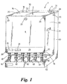
- a boiler assembly 1 comprises a removable domestic boiler unit 2 detachably connected to a manifold unit 4, the arrangement being such that the manifold unit 4 provides the boiler unit 2 with a connection interface to a heating pipework system (not shown).
- the boiler unit 2 may be quickly and simply removed from the manifold unit 4 and taken away to be serviced or repaired. In order that the heating system may be used while the servicing is being carried out a replacement boiler unit is connected to the manifold unit 4.
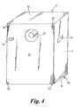
- the boiler unit 2 is a box-like shape comprising a removable front panel 8; two removable side panels 10, 12 each being formed with a handle recess 13; a removable top panel 14; a base panel 16 and a back panel 18.
- the removable panels of the manifold unit 4 are secured to the unit by a number of screws 20 (not shown in some Figures).
- the front panel 8 comprises a security lock 22, which helps to prevent unauthorised access to the boiler unit 2.
- any suitable security device may be used to prevent unauthorised access to the boiler unit 2.
- a rectangular instrumentation panel 24 that comprises a pressure gauge 26 and a timer 28 for turning the boiler unit 2 on and off.
- the timer 28 may also be used to indicate when a service is due or to indicate a fault.
- the boiler unit 2 contains an array of standard elements normally found in a domestic boiler including a burner unit 30, a heat exchanger 31, a combustion chamber 32, a fluid pump 34, a pressure switch 36 for a fan, a gas valve 38, a diverter valve 40 for the heat exchanger 31, a water pressure switch 42 and a PCB control box 44.
- the boiler unit 2 also comprises series of pipe connections 46.
- the pipe connections 46 are used as water inlet and water outlet ports for the boiler unit 2.
- One or more of the pipe connections 46 may be used as a gas feed port for the burner 30.
- the correct rating and design of the connections and the internal pipework would be chosen for the different functions of the connections 46 and internal pipework. Attached to each connection 46 there is an isolation valve 48 (see Figure 1 ).
- a guide channel 50 Disposed at each corner of the boiler unit 2 there is a guide channel 50 each of which extend from the back panel 18 in a direction towards the front of the boiler unit 2.
- the back panel 18 is also formed with an electrical plug element 54, and a circular port 52 that provides an exhaust for a flue of the boiler unit 2.
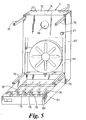
- the manifold unit 4 is a substantially L-shaped structure comprising a rectangular rear box section 60 and a rectangular base section 62.
- the rear box section 60 contains an expansion chamber 64 that is used for the pipework, which contains the heated water.
- An upper region of the rear box section 60 is formed with an electrical socket 67 and a flue port 66 for the exhaust gases of the boiler unit 2.
- the uppermost panel 70 of the rear box section 60 if formed with a series of circular holes 72.
- One or more pipes of the heating pipework system may use the holes 72 for access into the manifold.
- the uppermost panel 70 is also formed with a push-out circular section 74, which may be removed to allow access by an exhaust flue (not shown).
- the manifold unit 4 comprises four guide rails 76 extending in a direction substantially parallel to the base section 62. In the assembled state of the boiler assembly the rails 76 are received by the channels 50 of the boiler unit 2 and help provide support for the boiler unit 2.
- the base section 62 comprises a series of pipelines 78 the respective distal ends of which are held on a horizontal bracket 80. Connected to the respective distal ends of the pipelines 78 are respective isolation valves 82. In the assembled state the isolation valves 82 of the manifold unit 4 are connected to the isolation valves 48 of the boiler unit 2 (see Figure 1 ).
- the boiler assembly 1 may be fitted to an existing domestic heating system or alternatively a whole new heating pipework network may be fitted and connected to the boiler assembly 1.
- the manifold unit 4 is fixed to the wall or floor of the building.
- the various water pipes of the heating network are connected to the manifold unit 4. If the boiler unit 2 uses gas then the gas pipe is connected to the manifold unit 4 and the gas exhaust flue is connected to the manifold unit 4.
- any type of boiler may be used, such as an electric boiler or an oil boiler.
- the boiler unit 2 receives electrical power via the electrical plug 54 and socket 67.
- the maintenance person isolates the heating pipework system from the boiler unit 2 and the gas supply by closing the isolation valves 48 and 82.
- the connections between the respective isolation valves 48 and 82 are undone.
- the boiler unit 2 is then easily removed from the manifold unit 4 using the handles 13.
- the guide channels 50 slide on the rails 76, the electrical connection between plug 54 and the socket 67 is broken and the connection between the circular port 52 and the flue port 66 is broken. There is no need to remove the front panel 8 of the boiler unit 2 as the work is carried out off-site.
- a replacement boiler unit may be assembled onto the manifold unit 4 and all the connections made so that the heating system may be used while the original boiler unit is being serviced off-site.
- a particular benefit of the manifold unit 4 is that some of the elements of a boiler assembly, such as the expansion chamber 64 and the exhaust flue port 66, which do not normally require servicing may be contained in the manifold unit 4.
- the boiler unit 2 may contain only those elements that require regular servicing or are likely to need repair. The other elements of a domestic boiler assembly can be left behind when the boiler unit 2 is taken away.
- the boiler unit may comprise a device to measure pressure within one or more of the elements of the boiler assembly, a device for analysing moisture within the boiler unit and a device for measuring the various gases within the boiler assembly.
- the information from these various devices can be relayed to a remote computer management system via a modem.
- the computer management system monitors the information received from the devices. Any faults or potential faults are logged and such information may be used by a service technician.
- the boiler assembly may comprise remote management means operative to communicate with the boiler assembly via a modem, the boiler assembly providing analysis information to the management means.
- the management means may be used to monitor one or more boiler assembly(ies) remotely and detect potential faults.
- a boiler unit comprises a removable boiler unit that is detachably connected to a pipework system via a connection interface comprising quick release connections.
- the pipework system comprises isolation valve adjacent to the connections of the pipework system.
- the boiler unit may also comprise isolation valves adjacent to the connections.
- the isolation valves are used to prevent the flow of a fluid through the connections and they may be used to stop the flow of a fluid through the connections prior to the removal of the boiler unit from the pipework system.
- the connection interface may comprise an electrical power connection for providing the boiler unit with a power supply and a gas pipe connection for providing the boiler unit with a connection to a gas inlet pipe.
- the connection interface may also comprise an exhaust connection for providing the boiler unit with a connection to a gas outlet duct.
- a replacement boiler unit may be connected to the pipework system so that the heating system may be used while the original boiler unit is being serviced off-site.
- a boiler assembly 1 comprises a removable domestic boiler unit 2 detachably connected to a manifold unit 4, the arrangement being such that the manifold unit 4 provides the boiler unit 2 with a connection interface to a heating pipework system (not shown).
- the manifold unit 4 comprises four guide rails 90 extending in a direction substantially parallel to the base section 62.
- the rails 90 are received by channels 95 of the boiler 7 unit 2 and help provide support for the boiler unit 2.
- the guide rails 90 are each attached to the manifold at one of their respective end so forming a cantilever.
- the guide rails 90 each have a circular cross section.
- the distal end 91 of each guide rail 90 is a cone shape to aid the insertion into the respective channels 95.
- the boiler assembly 1 also comprises two removable support rails 94.
- the support rails 94 have an L-shaped vertical cross section and are used during the assembly and disassembly of the boiler unit 2 from the manifold unit 4 to provide support of the boiler unit 2. In the assembled state the support rails 94 can be removed from boiler assembly 1.
Landscapes
- Engineering & Computer Science (AREA)
- Physics & Mathematics (AREA)
- Thermal Sciences (AREA)
- Chemical & Material Sciences (AREA)
- Combustion & Propulsion (AREA)
- Mechanical Engineering (AREA)
- General Engineering & Computer Science (AREA)
- Incineration Of Waste (AREA)
- Air Supply (AREA)
- Heat-Pump Type And Storage Water Heaters (AREA)
- Steam Or Hot-Water Central Heating Systems (AREA)
- Housings, Intake/Discharge, And Installation Of Fluid Heaters (AREA)
Claims (36)
- Ensemble de chaudière (1) comprenant une unité de chaudière amovible (2) raccordée de manière détachable à une unité de collecteur (4), l'agencement étant tel que l'unité de collecteur (4) dote l'unité de chaudière (2), à l'usage, d'une interface de raccordement à un système de tuyauterie, alors que l'unité de collecteur (4) comprend une section arrière (60) et une section de base (62), caractérisée en ce que, au moins un rail de guidage (76) est positionné sur la section arrière (60) du collecteur de sorte que, pendant l'assemblage, l'unité de chaudière (2) est déplacée le long du rail de guidage qui supporte et guide l'unité de chaudière (2) sur l'unité de collecteur (4), et de sorte que, lorsqu'il est assemblé, le rail de guidage (76) éloigne l'unité de chaudière (2) au-dessus de la section de base (62) du collecteur et supporte le poids de l'unité de chaudière (2).
- Ensemble de chaudière (1) selon la revendication 1, dans lequel l'unité de chaudière (2) est une unité autonome comprenant les composants requis pour la production de chaleur, les composants étant un moteur de ventilateur, un commutateur de pression de ventilateur (36), une unité de brûleur (30), un échangeur de chaleur (31), une pompe de fluide (34), une soupape de gaz (38) et un boîtier de commande PCB (44).
- Ensemble de chaudière (1) selon la revendication 1, dans lequel l'unité de chaudière (2) est une unité autonome comprenant les composants requis pour la production d'eau chaude, les composants étant un moteur de ventilateur, un commutateur de pression de ventilateur (36), une unité de brûleur (30), un échangeur de chaleur (31), une pompe de fluide (34), une soupape de gaz (38) et un boîtier de commande PCB (44).
- Ensemble de chaudière (1) selon l'une quelconque des revendications 1 à 3, dans lequel l'interface de raccordement comprend une pluralité de raccordements entre l'unité de chaudière (2) et l'unité de collecteur (4).
- Ensemble de chaudière (1) selon la revendication 4, dans lequel le système de tuyauterie comprend une alimentation de fluide et un retour de fluide, chacun étant raccordé à l'unité de chaudière (2) par l'intermédiaire de l'unité de collecteur (4).
- Ensemble de chaudière (1) selon l'une quelconque des revendications 1 à 5, dans lequel l'unité de collecteur (4) dote l'unité de chaudière (2) d'une interface de raccordement à une alimentation de puissance.
- Ensemble de chaudière (1) selon la revendication 6, dans lequel l'alimentation de puissance est une alimentation de courant électrique.
- Ensemble de chaudière (1) selon la revendication 7, dans lequel l'interface de raccordement à l'alimentation de puissance est une prise mâle (54) et une prise femelle (67), l'agencement étant tel que la prise mâle (54) est reçue par la prise femelle (67) automatiquement lorsque l'unité de chaudière (2) est assemblée sur l'unité de collecteur (4).
- Ensemble de chaudière (1) selon l'une quelconque des revendications précédentes, dans lequel, dans un mode de réalisation de la présente invention, l'unité de collecteur (4) dote l'unité de chaudière (2) d'une interface de raccordement à un tuyau d'entrée de gaz.
- Ensemble de chaudière (1) selon la revendication 9, dans lequel l'unité de collecteur (4) dote l'unité de chaudière d'une interface de raccordement à un conduit de sortie de gaz.
- Ensemble de chaudière (1) selon la revendication 10, dans lequel l'unité de collecteur (4) dote l'unité de chaudière (2) d'un raccordement direct au conduit de sortie de gaz.
- Ensemble de chaudière (1) selon l'une quelconque des revendications 4 à 11, dans lequel les raccordements de l'interface de raccordement sont des raccordements à libération rapide.
- Ensemble de chaudière (1) selon l'une quelconque des revendications 4 à 12, dans lequel les raccordements de l'interface de raccordement comprennent des moyens pour isoler le système de tuyauterie, qui peut être utilisé avant de déconnecter l'unité de chaudière (2) de l'unité de collecteur (4).
- Ensemble de chaudière (1) selon l'une quelconque des revendications 4 à 13, dans lequel l'unité de chaudière (2) comprend des moyens pour isoler les raccordements.
- Ensemble de chaudière (1) selon l'une quelconque des revendications 4 à 14, dans lequel l'unité de collecteur (4) comprend des moyens pour isoler les raccordements.
- Ensemble de chaudière (1) selon la revendication 14 ou la revendication 15, dans lequel les moyens d'isolation peuvent empêcher l'écoulement du fluide à travers les raccordements.
- Ensemble de chaudière (1) selon l'une quelconque des revendications 13 à 16, dans lequel les moyens d'isolation sont positionnés à l'avant de l'ensemble de chaudière (1).
- Ensemble de chaudière (1) selon l'une quelconque des revendications précédentes, dans lequel l'ensemble de chaudière (1) peut être monté sur un mur ou reposer sur le sol.
- Ensemble de chaudière (1) selon l'une quelconque des revendications 13 à 18, dans lequel les moyens pour isoler le raccordement sont une série de soupapes (48, 82).
- Ensemble de chaudière (1) selon l'une quelconque des revendications précédentes, dans lequel le rail de guidage (76, 90) comprend une extrémité distale (91) formée avec une région progressivement rétrécie.
- Ensemble de chaudière (1) selon la revendication 20, dans lequel la région progressivement rétrécie du rail de guidage (76, 90) est en forme de cône.
- Ensemble de chaudière (1) selon la revendication 1, dans lequel l'ensemble de chaudière (1) comprend un rail de support (94) pour supporter l'unité de chaudière (2) pendant le démontage et le remontage.
- Ensemble de chaudière (1) selon la revendication 22, dans lequel le rail de support (94) est amovible de l'unité de collecteur (4).
- Ensemble de chaudière (1) selon l'une quelconque des revendications 21 à 23, dans lequel l'ensemble de chaudière ( 1 ) comprend une pluralité de rails de support (94) pour supporter l'unité de chaudière (2) pendant le démontage et le remontage.
- Ensemble de chaudière (1) selon l'une quelconque des revendications 21 à 24, dans lequel l'ensemble de chaudière (1) comprend deux rails de support (94), l'agencement étant tel, que pendant son utilisation, chaque rail de support (94) est disposé au niveau des coins inférieurs respectifs de l'unité de chaudière (2).
- Ensemble de chaudière (1) selon la revendication 1, dans lequel l'unité de chaudière (2) comprend des moyens pour mesurer la pression.
- Ensemble de chaudière (1) selon la revendication 1 ou selon la revendication 26, dans lequel l'unité de chaudière (2) comprend des moyens de commande pour contrôler le fonctionnement de l'ensemble de chaudière (1).
- Ensemble de chaudière (1) selon la revendication 1 ou la revendication 26, dans lequel l'unité de chaudière (2) comprend des moyens pour mesurer l'humidité à l'intérieur de l'unité de chaudière (2).
- Ensemble de chaudière (1) selon l'une quelconque des revendications 1 ou 26 à 28, dans lequel l'unité de chaudière (2) comprend des moyens pour analyser les gaz.
- Ensemble de chaudière (1) selon la revendication 1, dans lequel, dans un mode de réalisation de la présente invention, l'unité de collecteur (4) comprend une chambre d'expansion (64) pour l'installation de tuyauterie de chauffage.
- Ensemble de chaudière (1) selon la revendication 30, dans lequel l'unité de collecteur (4) comprend des moyens pour mesurer la pression.
- Ensemble de chaudière (1) selon la revendication 1, dans lequel l'ensemble de chaudière (1) comprend des moyens de sécurité pour empêcher le retrait non autorisé de l'unité de chaudière (2).
- Ensemble de chaudière (1) selon l'une quelconque des revendications précédentes, dans lequel l'unité de chaudière (2) est une chaudière domestique et le système de tuyauterie est un système de tuyauterie domestique.
- Ensemble de chaudière (1) selon l'une quelconque des revendications précédentes, dans lequel l'ensemble de chaudière (1) comprend des moyens de gestion à distance pouvant fonctionner pour communiquer avec l'ensemble de chaudière (1) par l'intermédiaire d'un modem, de sorte que l'ensemble de chaudière (1) fournit l'information d'analyse aux moyens de gestion.
- Système de chauffage caractérisé en ce que le système comprend un ensemble de chaudière (1) selon l'une quelconque des revendications 1 à 34.
- Procédé pour entretenir ou réparer un ensemble de chaudière (1) selon l'une quelconque des revendications 1 à 34, caractérisé en ce que le procédé comprend les étapes consistant à détacher et retirer une première unité de chaudière (2) d'une unité de collecteur (4) ; remplacer ensuite la première unité de chaudière (2) par une deuxième unité de chaudière (2) et raccorder la deuxième unité de chaudière (2) à l'unité de collecteur (4).
Priority Applications (1)
| Application Number | Priority Date | Filing Date | Title |
|---|---|---|---|
| EP10186215.9A EP2366962B1 (fr) | 2001-07-12 | 2002-07-11 | Unité de chaudière |
Applications Claiming Priority (2)
| Application Number | Priority Date | Filing Date | Title |
|---|---|---|---|
| GBGB0116989.5A GB0116989D0 (en) | 2001-07-12 | 2001-07-12 | Boiler unit |
| GB0116989 | 2001-07-12 |
Related Child Applications (8)
| Application Number | Title | Priority Date | Filing Date |
|---|---|---|---|
| EP10186215.9A Division EP2366962B1 (fr) | 2001-07-12 | 2002-07-11 | Unité de chaudière |
| EP10186215.9 Division-Into | 2010-10-01 | ||
| EP10186200.1 Division-Into | 2010-10-01 | ||
| EP10186225.8 Division-Into | 2010-10-01 | ||
| EP10186241.5 Division-Into | 2010-10-01 | ||
| EP10186176.3 Division-Into | 2010-10-01 | ||
| EP10186187.0 Division-Into | 2010-10-01 | ||
| EP10186235.7 Division-Into | 2010-10-01 |
Publications (3)
| Publication Number | Publication Date |
|---|---|
| EP1275910A2 EP1275910A2 (fr) | 2003-01-15 |
| EP1275910A3 EP1275910A3 (fr) | 2003-10-22 |
| EP1275910B1 true EP1275910B1 (fr) | 2011-03-09 |
Family
ID=9918351
Family Applications (2)
| Application Number | Title | Priority Date | Filing Date |
|---|---|---|---|
| EP02254899A Expired - Lifetime EP1275910B1 (fr) | 2001-07-12 | 2002-07-11 | Chaudière |
| EP10186215.9A Expired - Lifetime EP2366962B1 (fr) | 2001-07-12 | 2002-07-11 | Unité de chaudière |
Family Applications After (1)
| Application Number | Title | Priority Date | Filing Date |
|---|---|---|---|
| EP10186215.9A Expired - Lifetime EP2366962B1 (fr) | 2001-07-12 | 2002-07-11 | Unité de chaudière |
Country Status (5)
| Country | Link |
|---|---|
| EP (2) | EP1275910B1 (fr) |
| AT (1) | ATE501403T1 (fr) |
| DE (1) | DE60239373D1 (fr) |
| ES (2) | ES2610354T3 (fr) |
| GB (2) | GB0116989D0 (fr) |
Cited By (1)
| Publication number | Priority date | Publication date | Assignee | Title |
|---|---|---|---|---|
| EP4273456A1 (fr) * | 2022-05-06 | 2023-11-08 | REHAU Industries SE & Co. KG | Dispositif de raccordement pour un générateur de chaleur dans un équipement technique de construction, agencement de générateur de chaleur d'un équipement technique de construction et procédé de raccordement d'un générateur de chaleur à un équipement technique de construction |
Families Citing this family (6)
| Publication number | Priority date | Publication date | Assignee | Title |
|---|---|---|---|---|
| AT503217B1 (de) * | 2006-01-19 | 2007-11-15 | Vaillant Austria Gmbh | Heizgerät mit elektrischen anschlüssen |
| GB201016902D0 (en) * | 2010-10-07 | 2010-11-24 | Chamberlain Luke | A boiler assembly comprising a removable boiler unit |
| FR3004521B1 (fr) * | 2013-04-10 | 2016-11-04 | Atlantic Climatisation Et Ventilation | Dispositif de support d'un chauffe-eau thermodynamique gaine, systeme de support, chauffe-eau thermodynamique gaine et procede de fixation correspondants |
| GB2580007B (en) * | 2018-02-09 | 2022-08-03 | Lukey Solutions Ltd | Removable boiler |
| FR3098570B1 (fr) * | 2019-07-12 | 2021-07-09 | Bdr Thermea Group | Dispositif de chauffage d’eau à pompe à chaleur |
| EP4102141A1 (fr) | 2021-06-11 | 2022-12-14 | BDR Thermea Group B.V. | Mécanisme de sécurité |
Family Cites Families (7)
| Publication number | Priority date | Publication date | Assignee | Title |
|---|---|---|---|---|
| EP0034312B1 (fr) * | 1980-02-14 | 1985-01-16 | Aeroquip GmbH | Accouplement à action rapide accouplable aussi sous pression |
| GB2246848B (en) * | 1990-07-04 | 1994-05-18 | Baxi Partnership Ltd | Gas boiler |
| US5044401A (en) * | 1990-11-20 | 1991-09-03 | Parker Hannifin Corporation | Integral valve and seal for a quick connect coupling |
| DE4407371A1 (de) * | 1994-03-05 | 1995-09-07 | Bosch Gmbh Robert | Heizgerät für Raumheizung und Brauchwassererwärmung |
| DE19524114C2 (de) * | 1995-07-03 | 1997-07-31 | Abb Patent Gmbh | Hydraulik- oder Pneumatikkupplung |
| NL1002098C2 (nl) * | 1996-01-15 | 1997-07-16 | Radson Alutherm Nv | Verwarmingstoestel. |
| AT411492B (de) * | 1999-01-19 | 2004-01-26 | Vaillant Gmbh | Anordnung mit einem wandheizgerät |
-
2001
- 2001-07-12 GB GBGB0116989.5A patent/GB0116989D0/en not_active Ceased
-
2002
- 2002-07-11 AT AT02254899T patent/ATE501403T1/de not_active IP Right Cessation
- 2002-07-11 ES ES10186215.9T patent/ES2610354T3/es not_active Expired - Lifetime
- 2002-07-11 DE DE60239373T patent/DE60239373D1/de not_active Expired - Lifetime
- 2002-07-11 ES ES02254899T patent/ES2362983T3/es not_active Expired - Lifetime
- 2002-07-11 EP EP02254899A patent/EP1275910B1/fr not_active Expired - Lifetime
- 2002-07-11 GB GB0216011A patent/GB2378747B/en not_active Expired - Fee Related
- 2002-07-11 EP EP10186215.9A patent/EP2366962B1/fr not_active Expired - Lifetime
Cited By (1)
| Publication number | Priority date | Publication date | Assignee | Title |
|---|---|---|---|---|
| EP4273456A1 (fr) * | 2022-05-06 | 2023-11-08 | REHAU Industries SE & Co. KG | Dispositif de raccordement pour un générateur de chaleur dans un équipement technique de construction, agencement de générateur de chaleur d'un équipement technique de construction et procédé de raccordement d'un générateur de chaleur à un équipement technique de construction |
Also Published As
| Publication number | Publication date |
|---|---|
| ATE501403T1 (de) | 2011-03-15 |
| ES2362983T3 (es) | 2011-07-18 |
| EP1275910A2 (fr) | 2003-01-15 |
| EP2366962B1 (fr) | 2016-09-07 |
| ES2610354T3 (es) | 2017-04-27 |
| EP1275910A3 (fr) | 2003-10-22 |
| DE60239373D1 (de) | 2011-04-21 |
| GB0116989D0 (en) | 2001-09-05 |
| EP2366962A1 (fr) | 2011-09-21 |
| GB0216011D0 (en) | 2002-08-21 |
| GB2378747A (en) | 2003-02-19 |
| GB2378747B (en) | 2005-08-24 |
Similar Documents
| Publication | Publication Date | Title |
|---|---|---|
| EP2815800B1 (fr) | Pompe à vide avec fonction de réduction des contaminants | |
| EP1275910B1 (fr) | Chaudière | |
| CA2662076A1 (fr) | Ameliorations apportees a des groupes compresseurs | |
| GB2410075A (en) | Boiler unit with remote management system | |
| EP2438964A1 (fr) | Équipement de génération de fumée traceuse pour essais de ventilation | |
| US20200370786A1 (en) | Removable Boiler | |
| CN208296291U (zh) | 一种便于检修的壁挂炉热水器 | |
| US20090044793A1 (en) | Furnace burner box | |
| US20160327308A1 (en) | Plug and play modular comfort device and interface template adapted to said plug and play modular comfort device | |
| JP2007139283A (ja) | 着脱式空調機及び着脱式空調機システム | |
| WO1991005977A1 (fr) | Systeme de pompe a chaleur dote d'un circuit refrigerant sous forme d'unite echangeable, et moyens permettant d'effectuer un tel echange | |
| EP2484990A2 (fr) | Ensemble de chaudière comportant une unité de chaudière amovible | |
| US20050263148A1 (en) | Modular burner/blower system and method | |
| US5975122A (en) | Replaceable flow-control assembly for use in a fluid flow line | |
| AU2002300309B2 (en) | Frame For Hot Water Supplier | |
| GB2568072A (en) | Gas Boiler Assembly and Method | |
| JP3660206B2 (ja) | 給湯装置 | |
| CN217685903U (zh) | 一种油田加热炉用模块化热能回收装置 | |
| JPH02263046A (ja) | 給湯暖房機 | |
| US6276307B1 (en) | Heating apparatus, housing and stand | |
| CN109708093A (zh) | 一种快速除垢水胆及其燃气蒸汽炉 | |
| EP1378712A1 (fr) | Ensemble de distribution d'un fluide pour un ou pour plusieurs circuits thermiques | |
| JPH08310488A (ja) | 油清浄機のユニット |
Legal Events
| Date | Code | Title | Description |
|---|---|---|---|
| PUAI | Public reference made under article 153(3) epc to a published international application that has entered the european phase |
Free format text: ORIGINAL CODE: 0009012 |
|
| AK | Designated contracting states |
Kind code of ref document: A2 Designated state(s): AT BE BG CH CY CZ DE DK EE ES FI FR GB GR IE IT LI LU MC NL PT SE SK TR |
|
| AX | Request for extension of the european patent |
Free format text: AL;LT;LV;MK;RO;SI |
|
| PUAL | Search report despatched |
Free format text: ORIGINAL CODE: 0009013 |
|
| AK | Designated contracting states |
Kind code of ref document: A3 Designated state(s): AT BE BG CH CY CZ DE DK EE ES FI FR GB GR IE IT LI LU MC NL PT SE SK TR |
|
| AX | Request for extension of the european patent |
Extension state: AL LT LV MK RO SI |
|
| RIC1 | Information provided on ipc code assigned before grant |
Ipc: 7F 24H 9/06 B Ipc: 7F 24H 9/20 B Ipc: 7F 24H 9/02 B Ipc: 7F 24H 9/12 A Ipc: 7F 24H 9/14 B |
|
| 17P | Request for examination filed |
Effective date: 20040408 |
|
| AKX | Designation fees paid |
Designated state(s): AT BE BG CH CY CZ DE DK EE ES FI FR GB GR IE IT LI LU MC NL PT SE SK TR |
|
| RAP1 | Party data changed (applicant data changed or rights of an application transferred) |
Owner name: CHAMBERLAIN, LUKE |
|
| RIN1 | Information on inventor provided before grant (corrected) |
Inventor name: CHAMBERLAIN, LUKE |
|
| GRAP | Despatch of communication of intention to grant a patent |
Free format text: ORIGINAL CODE: EPIDOSNIGR1 |
|
| GRAC | Information related to communication of intention to grant a patent modified |
Free format text: ORIGINAL CODE: EPIDOSCIGR1 |
|
| GRAS | Grant fee paid |
Free format text: ORIGINAL CODE: EPIDOSNIGR3 |
|
| GRAA | (expected) grant |
Free format text: ORIGINAL CODE: 0009210 |
|
| AK | Designated contracting states |
Kind code of ref document: B1 Designated state(s): AT BE BG CH CY CZ DE DK EE ES FI FR GB GR IE IT LI LU MC NL PT SE SK TR |
|
| REG | Reference to a national code |
Ref country code: GB Ref legal event code: FG4D |
|
| REG | Reference to a national code |
Ref country code: CH Ref legal event code: EP |
|
| REG | Reference to a national code |
Ref country code: IE Ref legal event code: FG4D |
|
| REF | Corresponds to: |
Ref document number: 60239373 Country of ref document: DE Date of ref document: 20110421 Kind code of ref document: P |
|
| REG | Reference to a national code |
Ref country code: DE Ref legal event code: R096 Ref document number: 60239373 Country of ref document: DE Effective date: 20110421 |
|
| REG | Reference to a national code |
Ref country code: NL Ref legal event code: T3 |
|
| REG | Reference to a national code |
Ref country code: ES Ref legal event code: FG2A Ref document number: 2362983 Country of ref document: ES Kind code of ref document: T3 Effective date: 20110718 |
|
| PG25 | Lapsed in a contracting state [announced via postgrant information from national office to epo] |
Ref country code: SE Free format text: LAPSE BECAUSE OF FAILURE TO SUBMIT A TRANSLATION OF THE DESCRIPTION OR TO PAY THE FEE WITHIN THE PRESCRIBED TIME-LIMIT Effective date: 20110309 Ref country code: GR Free format text: LAPSE BECAUSE OF FAILURE TO SUBMIT A TRANSLATION OF THE DESCRIPTION OR TO PAY THE FEE WITHIN THE PRESCRIBED TIME-LIMIT Effective date: 20110610 |
|
| PG25 | Lapsed in a contracting state [announced via postgrant information from national office to epo] |
Ref country code: BG Free format text: LAPSE BECAUSE OF FAILURE TO SUBMIT A TRANSLATION OF THE DESCRIPTION OR TO PAY THE FEE WITHIN THE PRESCRIBED TIME-LIMIT Effective date: 20110609 Ref country code: CY Free format text: LAPSE BECAUSE OF FAILURE TO SUBMIT A TRANSLATION OF THE DESCRIPTION OR TO PAY THE FEE WITHIN THE PRESCRIBED TIME-LIMIT Effective date: 20110309 Ref country code: AT Free format text: LAPSE BECAUSE OF FAILURE TO SUBMIT A TRANSLATION OF THE DESCRIPTION OR TO PAY THE FEE WITHIN THE PRESCRIBED TIME-LIMIT Effective date: 20110309 Ref country code: FI Free format text: LAPSE BECAUSE OF FAILURE TO SUBMIT A TRANSLATION OF THE DESCRIPTION OR TO PAY THE FEE WITHIN THE PRESCRIBED TIME-LIMIT Effective date: 20110309 |
|
| PG25 | Lapsed in a contracting state [announced via postgrant information from national office to epo] |
Ref country code: BE Free format text: LAPSE BECAUSE OF FAILURE TO SUBMIT A TRANSLATION OF THE DESCRIPTION OR TO PAY THE FEE WITHIN THE PRESCRIBED TIME-LIMIT Effective date: 20110309 |
|
| PG25 | Lapsed in a contracting state [announced via postgrant information from national office to epo] |
Ref country code: PT Free format text: LAPSE BECAUSE OF FAILURE TO SUBMIT A TRANSLATION OF THE DESCRIPTION OR TO PAY THE FEE WITHIN THE PRESCRIBED TIME-LIMIT Effective date: 20110711 Ref country code: EE Free format text: LAPSE BECAUSE OF FAILURE TO SUBMIT A TRANSLATION OF THE DESCRIPTION OR TO PAY THE FEE WITHIN THE PRESCRIBED TIME-LIMIT Effective date: 20110309 |
|
| PG25 | Lapsed in a contracting state [announced via postgrant information from national office to epo] |
Ref country code: SK Free format text: LAPSE BECAUSE OF FAILURE TO SUBMIT A TRANSLATION OF THE DESCRIPTION OR TO PAY THE FEE WITHIN THE PRESCRIBED TIME-LIMIT Effective date: 20110309 Ref country code: CZ Free format text: LAPSE BECAUSE OF FAILURE TO SUBMIT A TRANSLATION OF THE DESCRIPTION OR TO PAY THE FEE WITHIN THE PRESCRIBED TIME-LIMIT Effective date: 20110309 |
|
| PLBE | No opposition filed within time limit |
Free format text: ORIGINAL CODE: 0009261 |
|
| STAA | Information on the status of an ep patent application or granted ep patent |
Free format text: STATUS: NO OPPOSITION FILED WITHIN TIME LIMIT |
|
| 26N | No opposition filed |
Effective date: 20111212 |
|
| PG25 | Lapsed in a contracting state [announced via postgrant information from national office to epo] |
Ref country code: MC Free format text: LAPSE BECAUSE OF NON-PAYMENT OF DUE FEES Effective date: 20110731 Ref country code: DK Free format text: LAPSE BECAUSE OF FAILURE TO SUBMIT A TRANSLATION OF THE DESCRIPTION OR TO PAY THE FEE WITHIN THE PRESCRIBED TIME-LIMIT Effective date: 20110309 |
|
| REG | Reference to a national code |
Ref country code: CH Ref legal event code: PL |
|
| GBPC | Gb: european patent ceased through non-payment of renewal fee |
Effective date: 20110711 |
|
| REG | Reference to a national code |
Ref country code: DE Ref legal event code: R097 Ref document number: 60239373 Country of ref document: DE Effective date: 20111212 |
|
| PG25 | Lapsed in a contracting state [announced via postgrant information from national office to epo] |
Ref country code: LI Free format text: LAPSE BECAUSE OF NON-PAYMENT OF DUE FEES Effective date: 20110731 Ref country code: CH Free format text: LAPSE BECAUSE OF NON-PAYMENT OF DUE FEES Effective date: 20110731 |
|
| PG25 | Lapsed in a contracting state [announced via postgrant information from national office to epo] |
Ref country code: GB Free format text: LAPSE BECAUSE OF NON-PAYMENT OF DUE FEES Effective date: 20110711 |
|
| PG25 | Lapsed in a contracting state [announced via postgrant information from national office to epo] |
Ref country code: LU Free format text: LAPSE BECAUSE OF NON-PAYMENT OF DUE FEES Effective date: 20110711 |
|
| PG25 | Lapsed in a contracting state [announced via postgrant information from national office to epo] |
Ref country code: TR Free format text: LAPSE BECAUSE OF FAILURE TO SUBMIT A TRANSLATION OF THE DESCRIPTION OR TO PAY THE FEE WITHIN THE PRESCRIBED TIME-LIMIT Effective date: 20110309 |
|
| REG | Reference to a national code |
Ref country code: FR Ref legal event code: PLFP Year of fee payment: 15 |
|
| REG | Reference to a national code |
Ref country code: FR Ref legal event code: PLFP Year of fee payment: 16 |
|
| REG | Reference to a national code |
Ref country code: FR Ref legal event code: PLFP Year of fee payment: 17 |
|
| PGFP | Annual fee paid to national office [announced via postgrant information from national office to epo] |
Ref country code: NL Payment date: 20200729 Year of fee payment: 19 |
|
| PGFP | Annual fee paid to national office [announced via postgrant information from national office to epo] |
Ref country code: ES Payment date: 20200813 Year of fee payment: 19 Ref country code: IE Payment date: 20200731 Year of fee payment: 19 Ref country code: FR Payment date: 20200728 Year of fee payment: 19 Ref country code: DE Payment date: 20200831 Year of fee payment: 19 |
|
| PGFP | Annual fee paid to national office [announced via postgrant information from national office to epo] |
Ref country code: IT Payment date: 20200727 Year of fee payment: 19 |
|
| REG | Reference to a national code |
Ref country code: DE Ref legal event code: R119 Ref document number: 60239373 Country of ref document: DE |
|
| REG | Reference to a national code |
Ref country code: NL Ref legal event code: MM Effective date: 20210801 |
|
| PG25 | Lapsed in a contracting state [announced via postgrant information from national office to epo] |
Ref country code: DE Free format text: LAPSE BECAUSE OF NON-PAYMENT OF DUE FEES Effective date: 20220201 |
|
| PG25 | Lapsed in a contracting state [announced via postgrant information from national office to epo] |
Ref country code: NL Free format text: LAPSE BECAUSE OF NON-PAYMENT OF DUE FEES Effective date: 20210801 Ref country code: FR Free format text: LAPSE BECAUSE OF NON-PAYMENT OF DUE FEES Effective date: 20210731 |
|
| PG25 | Lapsed in a contracting state [announced via postgrant information from national office to epo] |
Ref country code: IT Free format text: LAPSE BECAUSE OF NON-PAYMENT OF DUE FEES Effective date: 20210711 Ref country code: IE Free format text: LAPSE BECAUSE OF NON-PAYMENT OF DUE FEES Effective date: 20210711 |
|
| REG | Reference to a national code |
Ref country code: ES Ref legal event code: FD2A Effective date: 20220831 |
|
| PG25 | Lapsed in a contracting state [announced via postgrant information from national office to epo] |
Ref country code: ES Free format text: LAPSE BECAUSE OF NON-PAYMENT OF DUE FEES Effective date: 20210712 |