EP1275740A1 - Heating furnace with regenerative burners and method of operating the heating furnace - Google Patents
Heating furnace with regenerative burners and method of operating the heating furnace Download PDFInfo
- Publication number
- EP1275740A1 EP1275740A1 EP01273342A EP01273342A EP1275740A1 EP 1275740 A1 EP1275740 A1 EP 1275740A1 EP 01273342 A EP01273342 A EP 01273342A EP 01273342 A EP01273342 A EP 01273342A EP 1275740 A1 EP1275740 A1 EP 1275740A1
- Authority
- EP
- European Patent Office
- Prior art keywords
- furnace
- burners
- heat
- exhaust gas
- heating furnace
- Prior art date
- Legal status (The legal status is an assumption and is not a legal conclusion. Google has not performed a legal analysis and makes no representation as to the accuracy of the status listed.)
- Granted
Links
Images










Classifications
-
- C—CHEMISTRY; METALLURGY
- C21—METALLURGY OF IRON
- C21D—MODIFYING THE PHYSICAL STRUCTURE OF FERROUS METALS; GENERAL DEVICES FOR HEAT TREATMENT OF FERROUS OR NON-FERROUS METALS OR ALLOYS; MAKING METAL MALLEABLE, e.g. BY DECARBURISATION OR TEMPERING
- C21D1/00—General methods or devices for heat treatment, e.g. annealing, hardening, quenching or tempering
- C21D1/34—Methods of heating
- C21D1/52—Methods of heating with flames
-
- F—MECHANICAL ENGINEERING; LIGHTING; HEATING; WEAPONS; BLASTING
- F23—COMBUSTION APPARATUS; COMBUSTION PROCESSES
- F23D—BURNERS
- F23D14/00—Burners for combustion of a gas, e.g. of a gas stored under pressure as a liquid
- F23D14/46—Details
- F23D14/66—Preheating the combustion air or gas
-
- F—MECHANICAL ENGINEERING; LIGHTING; HEATING; WEAPONS; BLASTING
- F23—COMBUSTION APPARATUS; COMBUSTION PROCESSES
- F23L—SUPPLYING AIR OR NON-COMBUSTIBLE LIQUIDS OR GASES TO COMBUSTION APPARATUS IN GENERAL ; VALVES OR DAMPERS SPECIALLY ADAPTED FOR CONTROLLING AIR SUPPLY OR DRAUGHT IN COMBUSTION APPARATUS; INDUCING DRAUGHT IN COMBUSTION APPARATUS; TOPS FOR CHIMNEYS OR VENTILATING SHAFTS; TERMINALS FOR FLUES
- F23L15/00—Heating of air supplied for combustion
- F23L15/02—Arrangements of regenerators
-
- F—MECHANICAL ENGINEERING; LIGHTING; HEATING; WEAPONS; BLASTING
- F27—FURNACES; KILNS; OVENS; RETORTS
- F27B—FURNACES, KILNS, OVENS OR RETORTS IN GENERAL; OPEN SINTERING OR LIKE APPARATUS
- F27B9/00—Furnaces through which the charge is moved mechanically, e.g. of tunnel type; Similar furnaces in which the charge moves by gravity
- F27B9/30—Details, accessories or equipment specially adapted for furnaces of these types
- F27B9/40—Arrangements of controlling or monitoring devices
-
- F—MECHANICAL ENGINEERING; LIGHTING; HEATING; WEAPONS; BLASTING
- F27—FURNACES; KILNS; OVENS; RETORTS
- F27D—DETAILS OR ACCESSORIES OF FURNACES, KILNS, OVENS OR RETORTS, IN SO FAR AS THEY ARE OF KINDS OCCURRING IN MORE THAN ONE KIND OF FURNACE
- F27D17/00—Arrangements for using waste heat; Arrangements for using, or disposing of, waste gases
- F27D17/10—Arrangements for using waste heat
- F27D17/17—Arrangements for using waste heat for preheating fluids, e.g. air or gases
-
- C—CHEMISTRY; METALLURGY
- C21—METALLURGY OF IRON
- C21D—MODIFYING THE PHYSICAL STRUCTURE OF FERROUS METALS; GENERAL DEVICES FOR HEAT TREATMENT OF FERROUS OR NON-FERROUS METALS OR ALLOYS; MAKING METAL MALLEABLE, e.g. BY DECARBURISATION OR TEMPERING
- C21D9/00—Heat treatment, e.g. annealing, hardening, quenching or tempering, adapted for particular articles; Furnaces therefor
- C21D9/0081—Heat treatment, e.g. annealing, hardening, quenching or tempering, adapted for particular articles; Furnaces therefor for slabs; for billets
-
- F—MECHANICAL ENGINEERING; LIGHTING; HEATING; WEAPONS; BLASTING
- F27—FURNACES; KILNS; OVENS; RETORTS
- F27B—FURNACES, KILNS, OVENS OR RETORTS IN GENERAL; OPEN SINTERING OR LIKE APPARATUS
- F27B9/00—Furnaces through which the charge is moved mechanically, e.g. of tunnel type; Similar furnaces in which the charge moves by gravity
- F27B9/30—Details, accessories or equipment specially adapted for furnaces of these types
- F27B9/36—Arrangements of heating devices
- F27B2009/3638—Heaters located above and under the track
-
- F—MECHANICAL ENGINEERING; LIGHTING; HEATING; WEAPONS; BLASTING
- F27—FURNACES; KILNS; OVENS; RETORTS
- F27D—DETAILS OR ACCESSORIES OF FURNACES, KILNS, OVENS OR RETORTS, IN SO FAR AS THEY ARE OF KINDS OCCURRING IN MORE THAN ONE KIND OF FURNACE
- F27D17/00—Arrangements for using waste heat; Arrangements for using, or disposing of, waste gases
- F27D17/10—Arrangements for using waste heat
- F27D17/12—Arrangements for using waste heat using heat storage
- F27D17/13—Arrangements for using waste heat using heat storage using regenerative heat exchangers
-
- F—MECHANICAL ENGINEERING; LIGHTING; HEATING; WEAPONS; BLASTING
- F27—FURNACES; KILNS; OVENS; RETORTS
- F27D—DETAILS OR ACCESSORIES OF FURNACES, KILNS, OVENS OR RETORTS, IN SO FAR AS THEY ARE OF KINDS OCCURRING IN MORE THAN ONE KIND OF FURNACE
- F27D19/00—Arrangements of controlling devices
- F27D2019/0028—Regulation
- F27D2019/0031—Regulation through control of the flow of the exhaust gases
-
- F—MECHANICAL ENGINEERING; LIGHTING; HEATING; WEAPONS; BLASTING
- F27—FURNACES; KILNS; OVENS; RETORTS
- F27D—DETAILS OR ACCESSORIES OF FURNACES, KILNS, OVENS OR RETORTS, IN SO FAR AS THEY ARE OF KINDS OCCURRING IN MORE THAN ONE KIND OF FURNACE
- F27D99/00—Subject matter not provided for in other groups of this subclass
- F27D99/0001—Heating elements or systems
- F27D99/0033—Heating elements or systems using burners
- F27D2099/0053—Burner fed with preheated gases
- F27D2099/0056—Oxidant
-
- Y—GENERAL TAGGING OF NEW TECHNOLOGICAL DEVELOPMENTS; GENERAL TAGGING OF CROSS-SECTIONAL TECHNOLOGIES SPANNING OVER SEVERAL SECTIONS OF THE IPC; TECHNICAL SUBJECTS COVERED BY FORMER USPC CROSS-REFERENCE ART COLLECTIONS [XRACs] AND DIGESTS
- Y02—TECHNOLOGIES OR APPLICATIONS FOR MITIGATION OR ADAPTATION AGAINST CLIMATE CHANGE
- Y02E—REDUCTION OF GREENHOUSE GAS [GHG] EMISSIONS, RELATED TO ENERGY GENERATION, TRANSMISSION OR DISTRIBUTION
- Y02E20/00—Combustion technologies with mitigation potential
- Y02E20/34—Indirect CO2mitigation, i.e. by acting on non CO2directly related matters of the process, e.g. pre-heating or heat recovery
Definitions
- This invention concerns a method of optimally controlling the furnace pressure of a heating furnace.
- This invention relates to a method of controlling the atmosphere in a heating furnace and, particularly, a method of suppressing increase of an oxygen concentration in the atmosphere.
- This invention relates to an operation method of a heating furnace having heat regenerating burners and a heating furnace, particularly, to an operation method for conducting alternate combustion of paired burners in heat regenerating burners advantageously and a heating furnace used directly for the operation.
- This invention concerns a method of measuring the concentration of an atmospheric gas in a heating furnace and a heating furnace.
- a heating furnace for steel materials is used with an aim of re-heating steel pieces roughly rolled in a blooming factory or continuously rolling cast pieces into final products to a predetermined temperature suitable to rolling.
- the heating furnace is generally classified into a batch type and continuous type. Since they have respective advantages and drawbacks , they are used selectively depending on the purposes. Since the continuous heating furnace is suitable to mass production in recent years, they have been often been used, for example, in iron making plants.
- Fig. 1 shows a typical example of a cross sectional view for a continuous heating furnace. It generally comprises a preheating zone 1, a heating zone 2 and a soaking zone 3 successively from the side of charging steel materials. At least the heating zone 2 and the soaking zone 3 are heated to and kept at a predetermined temperature by burners 4. Steel material 5 introduced from a charging door 1a into the preheating zone 1 are moved on a transportation path 6 and heated to a predetermined temperature by way of the heating zone 2 and the soaking zone 3 and then delivered to the outside of the furnace from an extraction door 3a on the exit side of the soaking zone 3.
- Exhaust gases formed by combustion of the burners 4 are discharged from a stack 7 disposed on the entrance of the preheating zone 1 to the outside of the furnace.
- 7a denotes a recuperator for heat exchange of the sensible heat of an exhaust gas in the stack 7 to the sensible heat of a burner combustion gas
- 7b denotes a damper for furnace pressure control.
- heat loss particularly, radiation energy loss from the heating zone is large.
- the heat loss is suppressed by providing a preheating zone and a soaking zone at the inlet and the exit of the heating zone to partition the inside of the furnace into three parts.
- Steel materials to be charged in the continuous heating furnace includes, for example, cast pieces cooled to a normal temperature and hot charged materials sent directly after continuous casting to the rolling step, and the temperature on the inlet of the heating furnace is various.
- the heating temperature is varied and the processing amount of steel materials to be heated in the heating furnace also varies.
- the temperature in the heating furnace has to be controlled in according with such various conditions.
- the heating temperature is adjusted by increasing or decreasing the combustion amount of burners.
- the pressure in the furnace fluctuates in this case depending on the change of the combustion amount of the burners.
- JP-A-61-119987 discloses prevention of air intrusion from a charging door and an extraction door by controlling the furnace pressure set in the soaking zone of a heating furnace to a positive pressure relative to the pressure outside of the furnace (hereinafter simply referred to as positive pressure) in accordance with the amount of exhaust gases generated in the furnace. According to this method, it is possible to control the furnace pressure in an upper region of the furnace with the transportation path as a boundary (hereinafter referred to as an upper zone) to a positive pressure.
- JP-A-9-209032 discloses optimum control for a furnace pressure in accordance with the amount of combustion load on a heating furnace by a furnace pressure damper disposed in a stack through which exhaust gases from the heating furnace are passed in the upper region of the soaking zone.
- draft in the stack increases compared with the pressure loss due to the flow of exhaust gases from the inside of the furnace to the stack.
- the draft means that gases heated in the stack or in the furnace cause buoyancy to form a negative pressure.
- JP-A-7-316645 discloses a method of connecting a gas supply pipeline system to a stack on the exit of a recuperator and blowing a gas such as air into the stack thereby controlling the furnace pressure.
- This method requires to additionally provide a blower, various pipelines and a control system for controlling the furnace pressure. It involves a problem in that the installation cost is high and the maintenance is troublesome.
- ducts or accessory equipments are incorporated in a complicate manner at the periphery of the heating furnace, there is no room for installation space and additional prevision of the control system is difficult.
- JP-A-11-172326 proposes to jet out a combustible gas from a nozzle disposed near an extraction port separately from heating burners in a furnace and consume oxygen in intruding air upon combustion.
- FIG. 2A and Fig. 2B show an example for the structure of a heat regenerating burner. As shown in the Example of Fig. 2A and Fig.
- a heat regenerating burner comprises a pair of burners 40a and 40b opposed to each other between both side walls of a heating furnace soaking body 3, both-way channels 41a and 41b used for introducing combustion air from the outside of the furnace to each of the burners and for introducing exhaust gases from the inside of the furnace by way of each burner to the outside of the furnace, and heat regeneration bodies 42a and 42b disposed to the openings in each of the channels on the side of the burners in the illustrated example.
- the paired burners are alternately put to combustion. For example, as shown in Fig.
- the burner combustion operation is switched and, when a switching valve 44 for the both-way channels 41a and 41b is switched to change the connection with conduits for air and exhaust gas described above and then, as shown in Fig. 2B, a combustion air is supplied to the burner 40b from the both-way channel 41b by way of the heat regeneration body 42b, it is supplied while pre-heating the combustion air by utilizing the heat recovered in the heat regeneration body 42b in the step previously shown in Fig. 2A and, simultaneously, fuel 43b is supplied to burn the burner 40b.
- an exhaust gas in the furnace is sucked from the burner 40a opposed thereto and the exhaust gas is passed through the heat regeneration body 42a to recover the heat and then introduced to the both-way channel 41a and discharged out of the furnace.
- Operation for the heating furnace with less heat loss can be conducted by repeating the alternate combustion of the burners shown in Fig. 2A and Fig. 2B described above, for example, on every several tens seconds.
- a suction device 8 for the suction of the exhaust gas from the burner in a not combustion state, a suction device 8, for example, a suction blower is disposed to the end of a path 45 for sucking by way of the heat regeneration body 42b or 42b from the burner 40a or 40b, for example, as shown in Fig. 2A and 2B, and the exhaust gas from the burners is sucked by driving the suction device 8.
- the temperature of the exhaust gas sucked from the burner and passed through the regeneration body also lowers.
- moistures or sulfur contents contained in the exhaust gas are condensed at the exit of the exhaust gas of the regeneration body or in the path 45 succeeding thereto. Liquids caused by condensation, so called drains may sometimes stagnate at the exit of the exhaust gas of the regeneration body.
- the path introducing the exhaust gas rendered to a low temperature from the burner through the heat regeneration body to the suction device is long. Drains are formed not only at the exit of the heat regeneration body but also in the course of the path. Then, drains formed on the path cause corrosion to the impeller of the suction device. When solid components contained in the drains damage the impeller by abrasion, it may cause a worry of developing to fatal accidents. Accordingly, in the heating furnace having the heat regenerating burners, the suction device for the exhaust gas has been checked frequently. Further, it has also brought about a problem for the increase of the cost requiring for frequent maintenance such as exchange of the impeller of the suction device.
- JP-A-10-30812 discloses a device shown in Fig. 3.
- An exhaust gas in a heating furnace (for example, in soaking zone 3) is flowed through a by pass pipe 51 to an exhaust gas pipeline channel 50 separately from a channel of discharge through a burner 40a and an exhaust gas pipeline channel 50 to the outside of the furnace. It is disclosed that the temperature of the exhaust gas pipeline channel 50 is kept above a dew point of the exhaust gas with this constitution.
- JP-A-10-30812 can solve various problems regarding the drains in a case of combustion at low load, it can not still solve the problem that the operation of the suction device becomes unstable. Further, since control valves are present respectively to the exhaust gas 50 and the bypath pipeline 51 described in the publication, this also results in a problem that the control therefor is complicated.
- the atmosphere in the furnace of the continuous heating furnace For keeping the surface of the steel materials during heating satisfactory, it is important to strictly control the atmosphere in the furnace of the continuous heating furnace. For example, when the oxygen concentration in the furnace atmosphere increases, surface oxidation, nitridation or carburization of materials to be heated such as steel materials charged in the furnace are promoted and, when they are rolled as they are, the surface quality of the products is deteriorated. For improving or keeping the product quality, it is necessary to suppress increase for the oxygen concentration in the furnace atmosphere. For this purpose, it is important to exactly measure the oxygen concentration in the furnace atmosphere.
- Nitrogen gives an effect on nitridation on the surface of the steel materials, carbon monoxide can be utilized for the detection of incomplete combustion of burners and oxynitrides are necessary for the administration of environmental discharge standard values.
- JP-A-62-40312 discloses that each of the probes for measuring the oxygen concentration and the Co concentration in the heating furnace is made moveable, concentration is measured at plural measuring positions and an average concentration value is determined to amend and control the air ratio in the burners.
- JP-A-9-53120 discloses a heating furnace in which a partition wall is located inside of the furnace wall of the heating furnace on the extraction side and below the skid along the lateral direction of the furnace, and an oxygen densitometer and an exhaust pipe for discharging the atmospheric gas to the outside of the furnace are disposed between the partition wall and the furnace wall on the extraction side. It is disclosed that flow rate in the exhaust pipe is controlled while measuring the oxygen density by using the oxygen densitometer in the heating furnace.
- a probe for conducting measurement by the oxygen densitometer between the partition wall and the furnace wall on the extraction side, a probe has to be inserted from the hearth or furnace wall.
- the probe is inserted from the hearth, since probe is damaged or clogged due to dropping and deposition of scales, it is difficult to measure the density at high reliability for a long period of time.
- the probe is inserted from the furnace wall, since the probe is exposed to high temperature region in the furnace and distorted, it may cause a worry that the measuring point is displaced or the probe is damaged.
- One of the objects of this invention is to provide a method of controlling a furnace pressure capable of reliably preventing air from intruding into a heating furnace.
- the present inventors have made an earnest study on the intrusion of air in a case where the pressure in the furnace becomes negative. Air intrudes from both of the charging door and the extraction door into the furnace. As shown in Fig. 1, a stack 7 is disposed just after the charging door 1a. Air intruding from the charging door 1a directly passes to the stack 7 and discharged out of the furnace. It has been found that air intruding through the charging door 1a less causes a factor of bringing about increase of the oxygen density in the furnace or lowering the temperature in the furnace. It is important to avoid the intrusion of the air from the extraction door in order to avoid increase of the oxygen concentration in the furnace or lowering of the temperature in the furnace. For this purpose, it has been found that it is important to properly control the furnace pressure in the soaking zone to which the extraction door is disposed.
- this invention provide a method of controlling a furnace pressure in a heating furnace using heat regenerating burners, in which a suction ratio of an exhaust gas from the burner to a heat regenerating body is adjusted in accordance with the combustion load on the entire heating furnace, thereby controlling the furnace pressure in a soaking zone.
- this invention provides a method of controlling a pressure in a heating furnace of disposing a recuperator in the midway of a stack for introducing an exhaust gas in the heating furnace to the outside of the furnace, preheating combustion air supplied to burners as a heat source of the heating furnace by the recuperator, and supplying dilution air to the stack at an inlet of the recuperator for protecting the recuperator against high temperature atmosphere, characterized by controlling the flow rate of the dilution air in accordance with the temperature of the exhaust gas on the inlet of the recuperator and the combustion load of the heating furnace, thereby controlling the furnace pressure.
- An object of this invention is to provide a method capable of reliably preventing intrusion of air from an extraction door into a heating furnace. Further, an object of this invention is to provide a heating furnace used for the method.
- An object of this invention is to provide an operation method for a heating furnace of not making the operation of an exhaust suction device unstable even in a case where combustion load on heat regenerating burners is small. Further an object of this invention is to provide a heating furnace used for the operation method for the heating furnace.
- An object of this invention is to provide a method capable of exactly measuring the concentration of ingredient gas of the atmosphere in the heating furnace by utilizing an existent facility.
- a further obj ect of this invention is to provide a heating furnace capable of measuring concentration of ingredient gas of the atmosphere in the heating furnace.
- an operation for heating furnace with less heat loss can be realized by conducting heating repeating the steps shown in Fig. 2A and Fig. 2B, for example, on every several tens seconds.
- the gist of this invention is as described below.
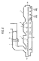
- Fig. 5 shows a continuous heating furnace used directly for the method according to this invention.
- the heating furnace is basically identical with that shown in Fig. 1, and this is an example in which heat regenerating burners 40a and 40b shown in Figs. 2A and 2B are disposed by plural sets at least to a lower region of a transpiration path 5 of a soaking zone 3.
- references 40a and 40b denote inclusively both-way parts and heat regeneration body.
- a suction ratio of an exhaust gas from the burners 40a and 40b to the heat regeneration bodies 42a and 42b are adjusted in accordance with a combustion load for the entire heating furnace to control the furnace pressure. Specifically, it has a feature in controlling the furnace pressure in a lower region at a positive pressure.
- a furnace pressure is actually measured by a furnace pressure gage disposed in a lower region of a soaking zone, and the flow rate of the exhaust gas passing through the heat regeneration body of the heat regenerating burner is adjusted by using a flow rate control valve to control the suction ratio of the exhaust gas in accordance with an aimed furnace pressure, thereby controlling the furnace pressure in a lower region, particularly, in a lower region of the soaking zone to the aimed furnace pressure.
- Fig. 6 shows a relation between an exhaust gas suction ratio and a surface pressure. It shows a relation between the furnace pressure in the lower region of the soaking zone and the exhaust gas suction ratio when the exhaust gas suction ratio is adjusted in accordance with the combustion load by the method described above.
- the exhaust gas suction ratio and the furnace pressure are in a substantially reversed proportion to each other. By adjusting the exhaust gas suction ratio, the furnace pressure can be controlled precisely.
- the exhaust gas suction ratio is a ratio of the amount of an exhaust gas sucked to the heat regenerating burners relative to the amount of an exhaust gas generated during combustion of the heat regenerating burners. This is determined by actually measuring the flow rate of the exhaust gas by using an exhaust gas flow meter disposed in an exhaust gas dust of heat regeneration burners.
- the furnace pressure is preferably controlled within a range from 0 to 0.5 mmAq in the lower region of the soaking zone by the adjustment of the exhaust gas suction ratio.
- the furnace pressure in the lower region of the soaking zone is set to 0.5 mmAq or higher, the furnace pressure in the upper region of the soaking zone is excessively high and the gas in the furnace is blown out of the furnace to possibly damage the extraction door. The fuel consumption is also worsened.
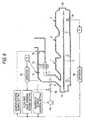
- Fig. 8 shows a continuous heating furnace used directly used according to this invention.
- the heating furnace has a constitution basically identical with that shown in Fig. 1. It has a structure of protecting a recuperator 7a by supplying dilution air 8 to the inlet of a recuperator 7a of a stack 7 in a case where the exhaust gas in the furnace introduced to a recuperator 7a exceeds the upper limit for the heat resistant temperature of the recuperator 7a.
- dilution air 8 is supplied also in a case where the furnace pressure in the soaking zone 3, particularly, a lower region thereof is lowered to less than an aimed value and, in addition, to a case where the exhaust gas temperature exceeds the heat resistant temperature of the recuperator 7a. It has a feature of controlling the furnace pressure in the lower region of the soaking zone 3 to a positive pressure by supplying the dilution air 8 by a predetermined flow rate.
- a measured furnace pressure value P.1 by a furnace pressure gage 3b disposed in the lower region of a soaking zone 3 and an aimed furnace pressure (positive pressure) are compared in a processor 9a. Based on the result, the processor 9a at first sets the opening degree for the damper 7b for furnace pressure control to conduct furnace pressure control.
- a processor 9b compares a measured temperature value T.1 by a thermometer 7c disposed on the inlet of the recuperator 7a in the stack 7 and an aimed temperature of the exhaust gas at that position, that is, the upper limit for the heat resistant temperature of the recuperator 7a.
- T.1 a measured temperature value
- T.1 approaches the upper limit for heat resistant temperature of the recuperator 7a
- appropriate number of blower rotation and opening degree of a flow rate control value are given, respectively, to a blower 8a for supplying dilution air 8 and a flow rate control value 8b by an instruction from the processor 9b.
- the temperature of the exhaust gas introduced to the recuperator 7a is decreased to an allowable range by supplying a predetermined flow rate of dilution air 8 to the stack 7 and mixing a dilution air 8 with the exhaust gas.
- the number of blower rotation and the opening degree of the flow rate control valve are fixed at the instance the measured temperature value T.1 is equal with the aimed temperature.
- Fig. 9 shows a relation between the opening degree of the flow rate control value for the dilution air 8 and the furnace pressure in the lower region of the soaking zone 3.
- the control range for the furnace pressure is extended greatly by the flow rate control for the dilution air 8. Even when the combustion load on the burners is small, the furnace pressure in the lower region of the soaking zone 3 can be made easily to a positive pressure by the supply of the dilution air 8. In addition, since existent facilities are utilized, there is no requirement for additional installation investment.
- an independent control system is introduced to a heating burner 40 disposed in the lower region of the furnace extraction end, among plural heating burners 4 located in the furnace, which is different from the control system for other heating burners 4 to control combustion of the heating burner 40 independently.
- the heating burners 4 in the heating furnace are usually located such that paired burners 4a and 4b are opposed to each other between both side walls of the heating furnace as shown in Fig. 13. Also for the heating burners 40 located in the lower region on the furnace extraction end, they are located as a pair of burners 40a and 40b.
- combustion of the heating burners 40a and 40b is controlled independently. As shown in Fig. 2A and Fig. 2B, during opening of the extraction door 3a, combustion operation is conducted such that burner flames of the heating burners 40a and 40b extend laterally for the opening width of the extraction port 3b. When the burner flames are formed for the width of the opening of the extraction port 3b, air intruding from the extraction port 3b into the furnace is at first shut by the burner flame and can not further intrude into the furnace. In addition, since oxygen in the intruding air is consumed by the burner flame, increase of the oxygen concentration in the furnace by intruding air can be prevented.
- the position for forming the burner flames of the heating burners 40a and 40b is preferably within such a range that the burner flame is not in contact with structure in the lower region of the extraction port and as close as the extraction port in the longitudinal direction of the furnace.
- the burner flames are situated at a position capable of closing the extraction fork opening and is a range not in contact with the hearth in the height direction of the furnace.
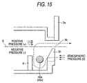
- the pressure distribution in the furnace is at a positive pressure relative to the pressure outside of the furnace (substantially atmospheric pressure) in a portion above the transportation path 6 as the boundary is and it is at a negative pressure in the lower region. That is, since the draft is usually increased to the lower region in the furnace, the furnace pressure exhibits a distribution that is lowered toward the downward.
- the damper 7b controls such that the furnace pressure is equal with the atmospheric pressure at the position for the height of the transportation path 6.
- Air intruding from the extraction port 3b, particularly, the extraction fork opening 3c proceeds toward the lower region of the transportation path 6 and is mostly taken into the burner flames of the heating burners 40a and 40b. Since the temperature of the intruding air is lower than the temperature in the furnace, a portion of the intruding air enters in the direction once sinking to the hearth. Since the intruding air proceeds deeply from the back of the heating burners 40a and 40b into the furnace, it tends to intrude although lithe into the furnace.
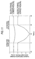
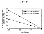
- Fig. 16 shows a relation between the air ratio in the heating burner at the extraction end and the combustion amount of the intruding air by the heating burner. It is apparent that when the air ratio in the heating burner is lowered, the combustion amount of the intruding air in the heating burner is increased.
- oxygen in the air intruding from the extraction port 3b can be burnt and consumed directly, which is effective for keeping the low oxygen concentration in the furnace atmosphere. It is advantageous to make the height of the partition wall 8 larger for the width between both side walls of the furnace within a range not interfering transportation devices from the hearth to the inside of the furnace for shutting the intruding air and forming the ascending stream.
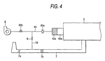
- Fig. 4 shows a discharging path for an exhaust gas in a continuous heating furnace which is used directly for the method of this invention.
- a pipeline 10 is disposed between a path 45 from the burners 40a or 40b by way of the heat regeneration body 42a or 42b and the stack 7 shown in Fig. 2A and Fig. 2B to the suction device 8 shown in Fig. 4. It has a feature in providing the pipeline channel 10 between the inlet side of the suction device 8 and the stack 7 for introducing the exhaust gas in the heating furnace to the outside of the furnace for introducing the exhaust gas in the stack 7 by way of the on/off valve 9 to the suction device 8.
- a flow meter 45a is disposed in the channel 45, in the inlet side of the suction device 8 upstream to the junction portion for the pipeline channel 10 for measuring the suction amount of the exhaust gas from the burners and judging the on/off timing of the on/off valve 9. Further, a flow rate control value 45b is disposed between the junction portion for the pipeline channel 10 and the channel 45, and the suction device 8 for controlling the total flow rate to a predetermined amount.
- the on/off valve 9 in the pipeline channel 10 is opened to introduce the exhaust gas in the stack 7 to the channel 45 on the inlet side of the suction device 8 to increase the operation load of the suction device 8.
- the temperature of the exhaust gas after mixing the exhaust gas in the stack and the low temperature exhaust gas passing through the heat regeneration body is adapted not to exceed the upper limit of the suction device 8, particularly, the endurance temperature of the impeller.
- the pipe diameter for the pipeline channel 10 is selected to control the flow rate of the exhaust gas and, simultaneously, equalize the pressure loss between the exhaust gas in the stack and the low temperature exhaust gas passing the heat regeneration body at the mixing point and the mixed exhaust gas is introduced to the suction device 8.
- This operation can easily attain increase of the operation load, for example, by 10% or more in the suction device 8 by which the problems described above for the extremely low load combustion can be overcome.
- the required minimum flow rate means a lower limit for the stable operation region upon design of the blower.
- the flow rate of the exhaust gas introduced to the suction device 8 can also be controlled by adapting the on/off valve 9 in the pipeline channel 10 as a flow rate control valve.
- operation for the flow rate control value is troublesome and, in addition, the mechanism thereof is complicated to also increase the installation cost.
- a simple and convenient means for merely opening/closing a pipeline channel 10 of a predetermined pipe diameter is adopted.
- a recuperator 7a is disposed to the upstream of the pipeline channel 10 in the stack 7. It is preferred for extending the duration life of the suction device 8 to pass the exhaust gas in the furnace through the recuperator 7a and supply the exhaust gas lowered for the temperature to the pipeline channel 10.
- the exhaust gas in the heating furnace is not mixed directly but the exhaust gas in the stack is mixed to the exhaust gas from the burners, it does not result in an external disturbance to the pressure in the hearth.
- the gas to be mixed with the exhaust gas from the burners is not restricted only to the exhaust gas in the stack but it may be a gas at a high temperature, that is, a hot blow.
- it may be air heated to high temperature, or a combustion device may be disposed separately and the combustion exhaust gas generated therefrom may be mixed.
- the exhaust gas sucked from the burner 40a or 40b in the heat regenerating burners is introduced by way of the both-way channel 41a or 41b to the outside of the furnace. Suction of the exhaust gas is conducted through the path shown in Fig. 17. That is, both-way channels 41a and 41b extending from plural sets of heat regenerating burners are collected into exhaust gas ducts 8a and 8b disposed respectively, on every burner groups at one side and the other side of the furnace wall and, further, the exhaust gas ducts 8a and 8b are collected into a single conduit 9, and the conduit 9 is in communication by way of a suction blower 10 to the stack 7 of the heating furnace. Then, the exhaust gas is introduced to the stack 7 and discharged out of the furnace by the suction of the suction blower 10 by way of the both-way channel 41a and 41b, the exhaust gas ducts 8a and 8b and then by way of the conduit 9.
- a probe 11 is inserted in the midway of the conduit 9 in the embodiment shown in Fig. 17.
- a portion of the exhaust gas flowing in the conduit 9 is sampled from the probe 11, and the concentration for each of the ingredients is measured by using an analyzer 19 for the sampled exhaust gas.
- concentration values thus obtained distinctly show the distribution of the furnace atmosphere, particularly, in the lateral direction of the furnace. They can be used as typical values for the concentration of the ingredients at the position in the furnace, for example, in the soaking zone 3 where the heat regenerating burners are located.
- the actual concentration for the ingredients in the furnace atmosphere can be measured by investigating the exhaust gas sucked from the heat regenerating burners,
- the average oxygen concentration in the furnace is a calculated value determined theoretically based on the flow rate of the gas charged in the burner, gas ingredient and the air ratio under the conditions where the extraction door and the charging door are closed, and under the condition of the furnace pressure set such that the intruding air in the furnace is at 0 Nm 3 /h.
- Other conditions are to be described specifically in the subsequent examples.
- the position for sampling the exhaust gas sucked from the heat regenerating burners is preferably at the downstream of the heat regeneration body of the heat regenerating burners as shown in Fig 17.
- the temperature of the exhaust gas recovered with heat by the heat regeneration body is naturally lower than the temperature of the furnace.
- a continuous heating furnace shown in Fig. 5 (height for transportation path from the furnace bottom: 0.5 m) was used, to which steel slabs each of 220 mm thickness, 1200 mm width and 9800 mm height were introduced and an operation for heating from room temperature to 1230°C was conducted.
- the specification for four sets of heat regenerating burners located in the soaking zone of the heating furnace is as described below.
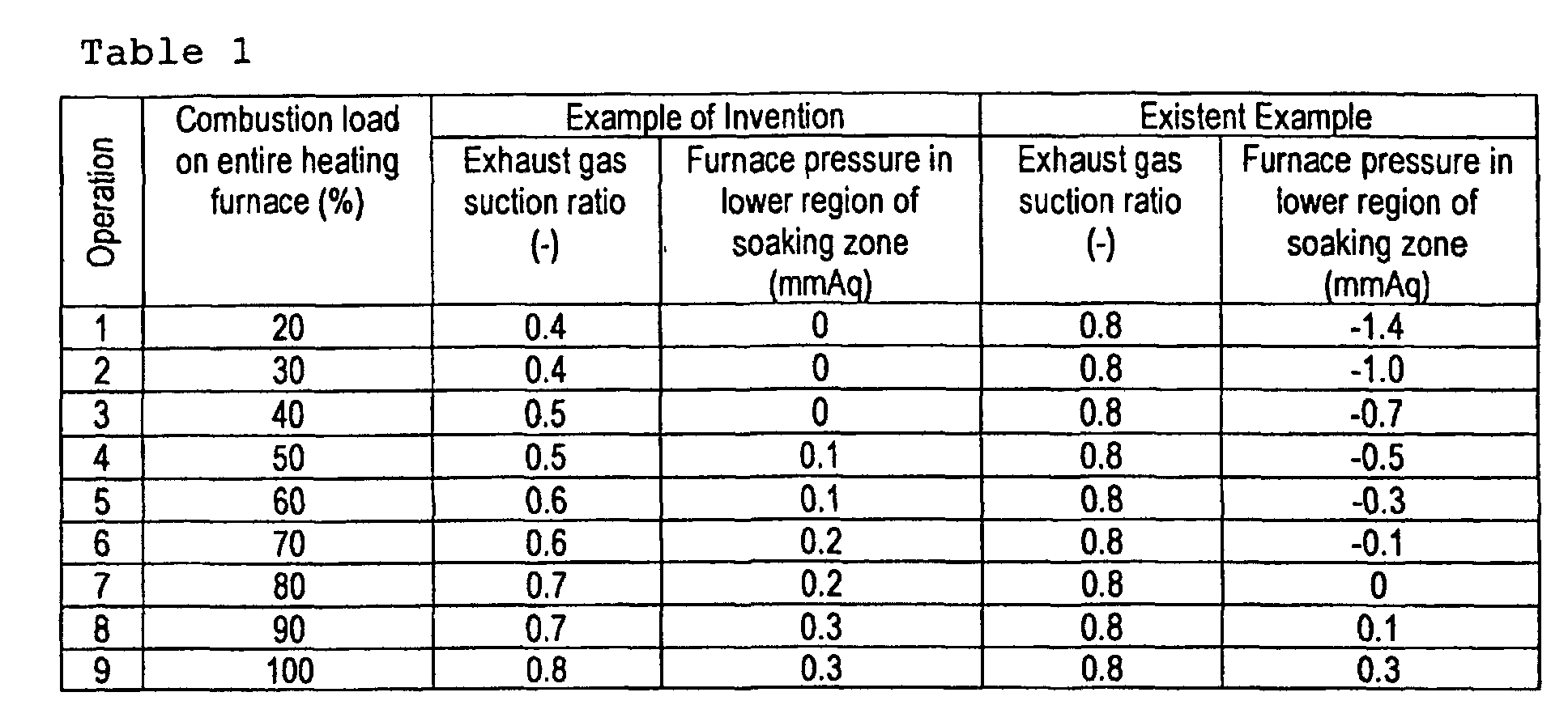
- the suction ratio of the exhaust gas from the burners was adjusted variously in accordance with the amount of combustion load on for the entire heating furnace to control the furnace pressure as shown in Table 1. Further, as a comparison, an existent operation by setting the suction ratio of the exhaust gas constant was also conducted. As a result, the furnace pressure can be stably controlled under various conditions of combustion load in the actual operation of the heating furnace and, as shown in Table 2, the concentration of oxygen in the furnace could be decreased greatly and the fuel consumption ratio and the slab failure ratio could be decreased compared with the existent method.
- a continuous heating furnace shown in Fig. 8 (height for transportation channel from the furnace bottom: 0.5 m) was used, to which steel slabs each of 220 mm thickness, 1200 mm width and 9800 mm height were introduced and an operation for heating from room temperature to 1230°C was conducted.
- the furnace pressure in the lower region and the oxygen concentration in the lower region of the soaking zone were measured while the combustion load in the heating furnace is changed variously and the extraction door is in the close state.
- the pressure in the furnace could be maintained at a positive level and the oxygen concentration could be kept to a low level by controlling the furnace pressure by dilution air.
- both the furnace pressure and the oxygen concentration varied greatly.
- the pressure of the furnace can be kept positive and the oxygen concentration can also be kept at a low level by controlling the furnace pressure by dilution air.
- a continuous heating furnace shown in Fig. 1 (height for transportation channel from the furnace bottom: 0.5 m) was used, to which steel slabs each of 220 mm thickness, 1200 mm width and 9800 mm height were introduced and an operation for heating from room temperature to 1230°C was conducted.
- the specification for four sets of heat regenerating burners located in the soaking zone of the heating furnace is as described below.
- the heating furnace described above After passing the exhaust gas sucked from the heat regenerating burners through the heat regeneration body, a portion of the exhaust gas was sampled from the probe 11 inserted in the midway of the conduit 9 and the oxygen concentration was measured for the sampled exhaust gas by using the analyzer 12.
- the range for measuring the oxygen concentration in the furnace was 0 to 21 vol% and the atmosphere temperature in the pipe in the conduit 9 was 200°C. Further, as a comparison, the oxygen concentration was measured by way of a probe inserted from the furnace wall of the soaking zone.
- the result of comparing the measured concentration values with the average oxygen concentration in the furnace is as shown in Fig. 18 and, in a case of measurement by the exhaust gas sucked from the heat regenerating burners in accordance with this invention, the error relative to the average oxygen concentration value in the furnace was less than 0.5%. On the contrary, in a case of measuring the oxygen concentration by way of the probe inserted from the furnace wall, the error relative to the average oxygen concentration value in the furnace was 1 to 3%.
- the furnace pressure can be controlled strictly.
- the furnace pressure control intrusion of air from the extraction door into the heating furnace can be prevented reliably.
- the deterioration of the quality of the material to be heated can be prevented.
- the fuel consumption in the heating furnace can be improved.
- operation of the suction device for the exhaust gas does not become unstable even when the combustion load on the heat regenerating burners is small. Since drains are not formed, the operation for the heating furnace is stabilized.
- the ingredient concentration in the atmosphere in the heating furnace can be measured exactly. Products of high quality can be produced by the control for the atmosphere in the furnace based on the measured values.
Landscapes
- Engineering & Computer Science (AREA)
- Chemical & Material Sciences (AREA)
- Mechanical Engineering (AREA)
- General Engineering & Computer Science (AREA)
- Combustion & Propulsion (AREA)
- Materials Engineering (AREA)
- Thermal Sciences (AREA)
- Crystallography & Structural Chemistry (AREA)
- Physics & Mathematics (AREA)
- Metallurgy (AREA)
- Organic Chemistry (AREA)
- Environmental & Geological Engineering (AREA)
- Air Supply (AREA)
- Waste-Gas Treatment And Other Accessory Devices For Furnaces (AREA)
- Regulation And Control Of Combustion (AREA)
- Gas Burners (AREA)
- Control Of Heat Treatment Processes (AREA)
- Tunnel Furnaces (AREA)
Abstract
Description
in which
| Air intrusion amount in furnace (Nm3/ | Oxygen concentration in furnace soaking zone (vol%) | Fuel consumption unit (index) | Failure rate (index) | |
| Example of Invention | less than 500 | Less than 1 | 0.95 | less than 0.1 |
| Existent Example | About 50,000 | 5-10 | 1.0 | 1.0 |

Claims (15)
- A method of controlling a furnace pressure by utilizing heat regenerating burners in a heating furnace having a preheating zone, a heating zone and a soaking zone, in which plural sets of heat regenerating burners each having a pair of burners each having a heat regeneration body and opposed to each other are disposed as a heat source for the soaking zone, wherein the method comprises alternately burning the burners of each pairs of the heat regenerating burners, sucking an exhaust gas in the furnace form the burners during not combustion state, introducing the exhaust gas to the heat regeneration body thereby recovering the heat in the exhaust gas to the heat regeneration body, and utilizing the recovered heat for the heating of combustion air of the burners upon combustion state, thereby conducting operation for the heating furnace, wherein the suction ratio of the exhaust gas from the burner to the heat regeneration body is controlled in accordance with the combustion load on the entire heating furnace to control the furnace pressure in the soaking zone.
- A method of controlling a furnace pressure in a heating furnace in which a recuperator is located in the midway of a stack for introducing an exhaust gas in the heating furnace to the outside of the furnace and combustion air supplied to burners as a heat source for the heating furnace is preheated by the recuperator, and dilution air is supplied to stack at a inlet of the recuperator for protecting the recuperator against high temperature atmosphere, wherein the flow rate of the dilution air is controlled in accordance with the temperature of the exhaust gas on the inlet of the recuperator and combustion load on the heating furnace, thereby controlling the furnace pressure.
- A method of controlling an atmosphere in a heating furnace, comprising independently controlling combustion of heating burners located in a lower region of a furnace extraction end among plural heating burners located in the heating furnace upon opening the extraction door of heating furnace, extending the flame of the burners for the width of the opening in the lateral direction of extraction port, and shutting the intruding path of air from the extraction port with the burner flame, thereby suppressing increase of the oxygen concentration in the furnace.
- A method of controlling an atmosphere in the heating furnace as defined in claim 3, wherein a partition wall standing vertically from the hearth is disposed to the heating burner located at the extraction end of the furnace on the inner side of the furnace thereby forming an ascending stream along with the partition wall, and carrying air intruding from the extraction port on the ascending stream.
- A method of controlling an atmosphere in the heating furnace as defined in claim 3 or 4, wherein combustion operation is conducted under a low air ratio of the heating burners disposed at the extraction end of the furnace.
- An operation method for a heating furnace having a heat regenerating burner in which a pair of burners each attached with a heat regeneration body and opposed to each other are disposed as a heat source, the method comprising alternately burning each pair of burners in the heat regenerating burner, sucking an exhaust gas in the furnace from the burners during not combustion state, introducing the exhaust gas to the heat regeneration body thereby recovering heat in the exhaust gas to the heat regeneration body, and utilizing the recovered heat for heating the combustion air of the burners during combustion state, thereby conducting operation for the heating furnace, wherein a hot blow is supplied to a suction device for sucking the exhaust gas in the furnace from the burner in the not-combustion state through the heat regeneration body in a case where the combustion load on the heat regenerating burner is small.
- An operation method for a heating furnace as defined in claim 6, wherein the hot blow is the exhaust gas in the stack for introducing the exhaust gas in the heating furnace to the outside of the furnace.
- A method of measuring the concentration of an atmosphere gas in a heating furnace comprising heat regenerating burners in which a pair of burners each attached with a heat regeneration body are opposed to each other as a heat source, by alternately burning each pair of burners of the heat regenerating burner, sucking an exhaust gas in the furnace from the burners during not-combustion state, introducing the exhaust gas to the heat regeneration body thereby recovering the heat in the exhaust gas to the heat regeneration body, and utilizing the recovered heat for heating the combustion air of the burners during combustion state, thereby conducting operation for the heating furnace wherein a portion of the exhaust gas sucked from the burners is introduced into an analyzer and measuring the concentration of ingredients in the exhaust gas.
- A method of measuring the concentration of the atmosphere gas in the heating furnace as defined in claim 8, wherein the measured value for the ingredient concentration of the exhaust gas sucked from the heat regenerating burners is used as a typical value for the ingredient concentrations in the zone of the heating furnace in which the heat regenerating burners are disposed.
- A heating furnace having plural heat regenerating burners in which a pair of burners each attached with a heat regeneration body are opposed to each other as a heat source, and adapted for alternately burning each pair of burners in the heat regenerating burners, sucking an exhaust gas in the furnace from the burners during not combustion state, introducing the exhaust gas to the heat regeneration body thereby recovering heat in the exhaust gas to the heat regeneration body, utilizing the recovered heat for heating the combustion air of the burners during combustion state thereby conducting operation, wherein at least the heat regenerating burners located in the lower region at the extraction end of the heating furnace have a combustion control system independent of other heat regenerating burners.
- A heating furnace as defined in claim 10, wherein a partition wall standing from the hearth is located at a position for putting the heat regenerating burner having an independent combustion control system relative to the extraction door of the heating furnace.
- A heating furnace having heat regenerating burners in which a pair of burners each attached with a heat regeneration body are opposed to each other as a heat source, and adapted for alternately burning each pair of burners in the heat regenerating burners, sucking an exhaust gas in the furnace from the burners during not combustion state, introducing the exhaust gas to the heat regeneration body thereby recovering heat in the exhaust gas to the heat regeneration body, utilizing the recovered heat for heating the combustion air of the burners during combustion state thereby conducting operation, a suction device is disposed at the end of the path for sucking the exhaust gas in the heating furnace from the burners during not-combustion state by way of the heat regeneration body, and a pipeline channel is disposed to the sucking path on the inlet side of the sucking device for introducing a hot blow by way of an ON/OFF valve to the suction device.
- A heating furnace as defined in claim 12, wherein the pipeline channel is connected with a stack for introducing the exhaust gas in the heating furnace to the outside of the furnace and introducing the exhaust gas in the heating furnace as a hot blow.
- A heating furnace as defined in claim 12 or 13, wherein a recuperator is disposed to the upstream of the pipeline channel in the stack.
- A heating furnace having plural heat regenerating burners in which a pair of burners each attached with a heat regeneration body are opposed to each other as a heat source, and adapted for alternately burning each pair of burners in the heat regenerating burners, sucking an exhaust gas in the furnace from the burners during not combustion state, introducing the exhaust gas to the heat regeneration body thereby recovering heat in the exhaust gas to the heat regeneration body and utilizing the recovered heat for heating the combustion air of the burners during combustion state thereby conducting operation, wherein a probe for sampling a portion of the exhaust gas and an analyzer for measuring the concentration of ingredients of the sampled exhaust gas are disposed in the midway of the path for discharging the exhaust gas in the heating furnace from the burner during not-combustion state by way of the heat regeneration body.
Priority Applications (1)
| Application Number | Priority Date | Filing Date | Title |
|---|---|---|---|
| EP06018722A EP1757707A3 (en) | 2001-01-17 | 2001-12-27 | Heating furnace having heat regenerating burners and operation method thereof |
Applications Claiming Priority (11)
| Application Number | Priority Date | Filing Date | Title |
|---|---|---|---|
| JP2001008524 | 2001-01-17 | ||
| JP2001008523 | 2001-01-17 | ||
| JP2001008523A JP3800008B2 (en) | 2001-01-17 | 2001-01-17 | Method of operating a heating furnace having a regenerative burner and a heating furnace |
| JP2001008524A JP3937729B2 (en) | 2001-01-17 | 2001-01-17 | Heating furnace atmosphere control method and heating furnace |
| JP2001014230A JP2002212630A (en) | 2001-01-23 | 2001-01-23 | Method of measuring atmospheric gas concentration in heating furnace and heating furnace |
| JP2001014230 | 2001-01-23 | ||
| JP2001016974A JP2002220620A (en) | 2001-01-25 | 2001-01-25 | Furnace pressure control method of heating furnace |
| JP2001016974 | 2001-01-25 | ||
| JP2001017017A JP2002220621A (en) | 2001-01-25 | 2001-01-25 | Furnace pressure control method using regenerative burner |
| JP2001017017 | 2001-01-25 | ||
| PCT/JP2001/011508 WO2002057501A1 (en) | 2001-01-17 | 2001-12-27 | Heating furnace with regenerative burners and method of operating the heating furnace |
Related Child Applications (1)
| Application Number | Title | Priority Date | Filing Date |
|---|---|---|---|
| EP06018722A Division EP1757707A3 (en) | 2001-01-17 | 2001-12-27 | Heating furnace having heat regenerating burners and operation method thereof |
Publications (3)
| Publication Number | Publication Date |
|---|---|
| EP1275740A1 true EP1275740A1 (en) | 2003-01-15 |
| EP1275740A4 EP1275740A4 (en) | 2005-03-02 |
| EP1275740B1 EP1275740B1 (en) | 2006-11-22 |
Family
ID=27531773
Family Applications (2)
| Application Number | Title | Priority Date | Filing Date |
|---|---|---|---|
| EP06018722A Withdrawn EP1757707A3 (en) | 2001-01-17 | 2001-12-27 | Heating furnace having heat regenerating burners and operation method thereof |
| EP01273342A Expired - Lifetime EP1275740B1 (en) | 2001-01-17 | 2001-12-27 | Method of operating a heating furnace with regenerative burners |
Family Applications Before (1)
| Application Number | Title | Priority Date | Filing Date |
|---|---|---|---|
| EP06018722A Withdrawn EP1757707A3 (en) | 2001-01-17 | 2001-12-27 | Heating furnace having heat regenerating burners and operation method thereof |
Country Status (10)
| Country | Link |
|---|---|
| US (1) | US6644962B2 (en) |
| EP (2) | EP1757707A3 (en) |
| KR (1) | KR100634776B1 (en) |
| CN (1) | CN100338236C (en) |
| AT (1) | ATE346172T1 (en) |
| BR (1) | BR0109303A (en) |
| CA (2) | CA2639404A1 (en) |
| DE (1) | DE60124691T2 (en) |
| TW (1) | TW524956B (en) |
| WO (1) | WO2002057501A1 (en) |
Cited By (3)
| Publication number | Priority date | Publication date | Assignee | Title |
|---|---|---|---|---|
| FR2905753A1 (en) * | 2006-09-13 | 2008-03-14 | Stein Heurtey | METHOD OF HEATING IN OVEN USING FUEL WITH LOW CALORIFIC POWER, AND OVEN USING THE SAME |
| EP2687801A4 (en) * | 2011-03-18 | 2014-08-20 | Ngk Insulators Ltd | TUNNEL OVEN FOR COOKING POROUS CERAMICS |
| CN117960845A (en) * | 2024-04-01 | 2024-05-03 | 中铁城建集团第一工程有限公司 | H-shaped steel straightening equipment and straightening method |
Families Citing this family (40)
| Publication number | Priority date | Publication date | Assignee | Title |
|---|---|---|---|---|
| KR100946071B1 (en) * | 2002-12-23 | 2010-03-10 | 주식회사 포스코 | External intrusion air cutoff device |
| US6997704B2 (en) * | 2003-02-28 | 2006-02-14 | Borgwarner Inc. | Method and apparatus to aid in the delubrification of parts |
| KR101020358B1 (en) * | 2003-07-07 | 2011-03-08 | 재단법인 포항산업과학연구원 | Heat recovery device for reheating furnace |
| KR101108617B1 (en) * | 2004-09-02 | 2012-01-31 | 재단법인 포항산업과학연구원 | Sensible heat recovery system of furnace flue gas |
| DE202007010480U1 (en) * | 2006-08-24 | 2007-10-04 | Lbe Feuerungstechnik Gmbh | Radiant heater for heating an industrial furnace |
| CN101165406B (en) * | 2006-10-19 | 2010-05-12 | 鞍钢股份有限公司 | A Regenerative Combustion Method Prolonging Reversing Time |
| CN101373067B (en) * | 2007-08-24 | 2010-05-19 | 宝山钢铁股份有限公司 | A kind of thermal storage combustion control method |
| JP4832501B2 (en) * | 2008-12-11 | 2011-12-07 | 中外炉工業株式会社 | Combustion control method of heat storage combustion type heat treatment furnace |
| JP4615045B2 (en) * | 2008-12-16 | 2011-01-19 | 中外炉工業株式会社 | Combustion control method of heat storage combustion type heat treatment furnace |
| KR101038116B1 (en) * | 2009-04-02 | 2011-05-31 | 재단법인 포항산업과학연구원 | Low pressure control method of regenerative heating furnace and its device |
| CN101832713A (en) * | 2010-04-30 | 2010-09-15 | 山西太钢不锈钢股份有限公司 | Method for improving combustion thermal efficiency of regenerative heating furnace |
| JP5404533B2 (en) * | 2010-06-03 | 2014-02-05 | 中外炉工業株式会社 | Combustion control method of heat storage combustion type heat treatment furnace |
| CN101967541B (en) * | 2010-10-28 | 2013-02-13 | 武汉钢铁(集团)公司 | Heating method for controlling decarburization in heavy rail billet furnace |
| TWI413554B (en) * | 2011-01-03 | 2013-11-01 | China Steel Corp | Furnace pressure control method |
| CN102260784A (en) * | 2011-07-11 | 2011-11-30 | 安徽精诚铜业股份有限公司 | Heating furnace |
| JP5849542B2 (en) * | 2011-09-05 | 2016-01-27 | 株式会社Ihi | Continuous heating furnace |
| JP6240371B2 (en) | 2011-09-05 | 2017-11-29 | 株式会社Ihi | Heating furnace and continuous heating furnace |
| KR101320117B1 (en) * | 2012-02-28 | 2013-10-18 | 현대제철 주식회사 | Door apparatus of heating furnace |
| CN103063806B (en) * | 2012-12-18 | 2015-02-25 | 秦皇岛首秦金属材料有限公司 | Method for detecting abnormity of remaining oxygen in thermal treatment furnace |
| TWI512258B (en) * | 2013-01-24 | 2015-12-11 | China Steel Corp | Energy saving method of setting the furnace pressure |
| KR101386053B1 (en) * | 2013-07-22 | 2014-04-17 | 주식회사 에스에이씨 | Apparatus and method of combustion exhaust control in regenerative reheating furnace |
| TWI573965B (en) * | 2014-11-12 | 2017-03-11 | 財團法人工業技術研究院 | Modification method of oxygen concentration for combustion system |
| US10366594B2 (en) * | 2015-05-04 | 2019-07-30 | Mountain Optech, Inc. | Oil and gas production facility emissions sensing and alerting device, system and method |
| US20160328943A1 (en) * | 2015-05-04 | 2016-11-10 | Moutain Optech, Inc. d/b/a Mountain Secure Systems | Oil and gas production facility emissions sensing and alerting device, system and method |
| CN104930485B (en) * | 2015-06-19 | 2017-03-08 | 上海优华系统集成技术股份有限公司 | A kind of flue gas waste heat recovery system and its recovery method and purposes |
| DE102016110170B3 (en) * | 2016-06-02 | 2017-11-23 | Kopf Holding Gmbh | Galvanizing furnace and method for operating a galvanizing furnace |
| CN106801139A (en) * | 2017-01-19 | 2017-06-06 | 本钢板材股份有限公司 | Annealing furnace optimization of air-fuel ratio method |
| WO2018148478A1 (en) | 2017-02-13 | 2018-08-16 | Bloom Engineering Company Inc. | Dual mode regenerative burner system and a method of heating a furnace using a dual mode regenerative burner system |
| CN108253789A (en) * | 2017-12-18 | 2018-07-06 | 醴陵友立特种陶瓷有限公司 | Multiple preparing heat-accumulating ceramic product shuttle kiln |
| CN108278906A (en) * | 2018-01-17 | 2018-07-13 | 上海曙佳科技发展有限公司 | Suitable for the optimal control method under the conditions of recuperative heater low load combustion |
| CN108716852A (en) * | 2018-06-13 | 2018-10-30 | 佛山市中晨窑炉设备有限公司 | A kind of kiln firing oxidation panel secondary combustion system |
| CN113804008B (en) * | 2020-06-12 | 2023-08-11 | 宝山钢铁股份有限公司 | Control method for improving temperature uniformity of heating furnace |
| CN111811257B (en) * | 2020-06-16 | 2021-12-21 | 首钢京唐钢铁联合有限责任公司 | Heating furnace combustion control method and device |
| CN113847821B (en) * | 2020-06-28 | 2023-10-17 | 宝山钢铁股份有限公司 | A pulse control method for a heating furnace burner and a furnace temperature control method for a pulse furnace |
| WO2022072588A1 (en) * | 2020-09-30 | 2022-04-07 | Owens-Brockway Glass Container Inc. | Submerged combustion melting exhaust systems |
| CN116536506A (en) * | 2022-01-25 | 2023-08-04 | 宝山钢铁股份有限公司 | Furnace pressure control method for an atmosphere annealing furnace |
| CN115125467B (en) * | 2022-07-12 | 2023-11-28 | 辛集市澳森金属制品有限公司 | Zinc-plating economizer system of utilization waste heat heating |
| JP2025089649A (en) * | 2023-12-04 | 2025-06-16 | Jfeスチール株式会社 | Heating furnace operation method and heating furnace |
| JP7633610B1 (en) * | 2023-12-04 | 2025-02-20 | Jfeスチール株式会社 | How to operate a heating furnace |
| CN117663161B (en) * | 2023-12-11 | 2024-05-14 | 星远智维邯郸环境科技有限公司 | Rotary heat accumulating type heating furnace |
Family Cites Families (18)
| Publication number | Priority date | Publication date | Assignee | Title |
|---|---|---|---|---|
| JPS61119987A (en) | 1984-11-14 | 1986-06-07 | 新日本製鐵株式会社 | Method of controlling furnace pressure of continuous type heating furnace |
| JPS6240312A (en) | 1985-08-15 | 1987-02-21 | Kawasaki Steel Corp | Method for controlling atmosphere in furnace |
| JP2521386B2 (en) * | 1991-10-31 | 1996-08-07 | 日本ファーネス工業株式会社 | Steel heating furnace |
| US5266027A (en) * | 1992-08-12 | 1993-11-30 | Ngk Insulators, Ltd. | Roller-hearth continuous furnace |
| JP2796027B2 (en) * | 1992-12-28 | 1998-09-10 | 日本鋼管株式会社 | Operating method of continuous heating furnace having regenerative burner |
| JP2589541Y2 (en) * | 1993-09-30 | 1999-01-27 | 石川島播磨重工業株式会社 | Steel heating furnace |
| JP2885072B2 (en) * | 1994-05-30 | 1999-04-19 | 住友金属工業株式会社 | Heating furnace control method |
| CN2199437Y (en) * | 1994-07-15 | 1995-05-31 | 机械工业部第五设计研究院 | Heat accumulation type high-temp. reheating burner |
| JP3379296B2 (en) | 1995-08-16 | 2003-02-24 | 日本鋼管株式会社 | Atmosphere control method of heating furnace |
| JP3617202B2 (en) * | 1995-10-19 | 2005-02-02 | Jfeスチール株式会社 | Heating furnace and operating method thereof |
| JPH09209032A (en) * | 1996-02-01 | 1997-08-12 | Nippon Steel Corp | Optimal furnace pressure control method for heating furnace |
| JPH109558A (en) * | 1996-06-25 | 1998-01-16 | Kawasaki Steel Corp | Waste gas temperature control method in regenerative combustion device |
| JP3478009B2 (en) | 1996-07-16 | 2003-12-10 | Jfeスチール株式会社 | Heating furnace with regenerative burner |
| JPH10185177A (en) * | 1996-12-24 | 1998-07-14 | Daido Steel Co Ltd | Regeneration burner type heating furnace |
| JPH11172326A (en) * | 1997-12-05 | 1999-06-29 | Kawasaki Steel Corp | Furnace atmosphere control method and apparatus |
| JPH11248151A (en) * | 1998-03-06 | 1999-09-14 | Kawasaki Steel Corp | Exhaust gas suction amount control method in regenerative combustion device |
| JP3733803B2 (en) * | 1999-09-27 | 2006-01-11 | Jfeスチール株式会社 | Furnace pressure control method for rotary hearth furnace |
| US6290492B1 (en) * | 2000-02-15 | 2001-09-18 | Air Products And Chemicals, Inc. | Method of reducing NOx emission from multi-zone reheat furnaces |
-
2001
- 2001-12-27 WO PCT/JP2001/011508 patent/WO2002057501A1/en not_active Ceased
- 2001-12-27 KR KR1020027012192A patent/KR100634776B1/en not_active Expired - Fee Related
- 2001-12-27 CA CA002639404A patent/CA2639404A1/en not_active Abandoned
- 2001-12-27 US US10/220,726 patent/US6644962B2/en not_active Expired - Fee Related
- 2001-12-27 AT AT01273342T patent/ATE346172T1/en not_active IP Right Cessation
- 2001-12-27 BR BR0109303-7A patent/BR0109303A/en not_active Application Discontinuation
- 2001-12-27 DE DE60124691T patent/DE60124691T2/en not_active Expired - Lifetime
- 2001-12-27 EP EP06018722A patent/EP1757707A3/en not_active Withdrawn
- 2001-12-27 EP EP01273342A patent/EP1275740B1/en not_active Expired - Lifetime
- 2001-12-27 CA CA002403221A patent/CA2403221C/en not_active Expired - Fee Related
- 2001-12-27 CN CNB018092470A patent/CN100338236C/en not_active Expired - Fee Related
-
2002
- 2002-01-16 TW TW091100620A patent/TW524956B/en not_active IP Right Cessation
Cited By (7)
| Publication number | Priority date | Publication date | Assignee | Title |
|---|---|---|---|---|
| FR2905753A1 (en) * | 2006-09-13 | 2008-03-14 | Stein Heurtey | METHOD OF HEATING IN OVEN USING FUEL WITH LOW CALORIFIC POWER, AND OVEN USING THE SAME |
| WO2008031937A3 (en) * | 2006-09-13 | 2008-05-15 | Stein Heurtey | Method of reheating in a furnace using a fuel of low calorific power, and furnace using this method |
| EA016077B1 (en) * | 2006-09-13 | 2012-01-30 | Фив Стэн | METHOD OF HEATING IN THE OVEN WITH THE USE OF FUEL WITH WEAK HEATING CAPACITY AND THE OVEN WHICH APPLIES THIS METHOD |
| EP2687801A4 (en) * | 2011-03-18 | 2014-08-20 | Ngk Insulators Ltd | TUNNEL OVEN FOR COOKING POROUS CERAMICS |
| US9650304B2 (en) | 2011-03-18 | 2017-05-16 | Ngk Insulators, Ltd. | Tunnel kiln for firing ceramic porous bodies |
| CN117960845A (en) * | 2024-04-01 | 2024-05-03 | 中铁城建集团第一工程有限公司 | H-shaped steel straightening equipment and straightening method |
| CN117960845B (en) * | 2024-04-01 | 2024-06-11 | 中铁城建集团第一工程有限公司 | H-shaped steel straightening equipment and straightening method |
Also Published As
| Publication number | Publication date |
|---|---|
| EP1757707A3 (en) | 2007-06-20 |
| CA2403221A1 (en) | 2002-07-25 |
| CN1427897A (en) | 2003-07-02 |
| CA2639404A1 (en) | 2002-07-25 |
| DE60124691T2 (en) | 2007-09-13 |
| US6644962B2 (en) | 2003-11-11 |
| TW524956B (en) | 2003-03-21 |
| CA2403221C (en) | 2009-02-17 |
| KR100634776B1 (en) | 2006-10-16 |
| US20030027095A1 (en) | 2003-02-06 |
| WO2002057501A1 (en) | 2002-07-25 |
| EP1275740B1 (en) | 2006-11-22 |
| EP1275740A4 (en) | 2005-03-02 |
| EP1757707A2 (en) | 2007-02-28 |
| BR0109303A (en) | 2002-12-17 |
| KR20020083180A (en) | 2002-11-01 |
| DE60124691D1 (en) | 2007-01-04 |
| ATE346172T1 (en) | 2006-12-15 |
| CN100338236C (en) | 2007-09-19 |
Similar Documents
| Publication | Publication Date | Title |
|---|---|---|
| US6644962B2 (en) | Heating furnace having heat regenerating burners and operation method thereof | |
| AU2010244307A1 (en) | Control process for an anode baking furnace and adapted furnace using such process | |
| US20090136884A1 (en) | Direct-Fired Furnace Utilizing An Inert Gas To Protect Products Being Thermally Treated In The Furnace | |
| CN1333087C (en) | Heating furnace with regenerative burners and method of operating heating furnace | |
| CA2198682A1 (en) | Furnace waste gas combustion control | |
| EP0233944A1 (en) | Continuous strip steel processing line having direct firing furnace | |
| CN101517100A (en) | Method of reheating in a furnace using a fuel of low calorific power, and furnace using this method | |
| JP4395994B2 (en) | Rapid heating method of ladle using regenerative burner | |
| JP4873325B2 (en) | In-furnace atmosphere control method for heating furnace | |
| JP3617202B2 (en) | Heating furnace and operating method thereof | |
| JP3147295B2 (en) | Sealing equipment for continuous annealing furnace | |
| JP3800008B2 (en) | Method of operating a heating furnace having a regenerative burner and a heating furnace | |
| JP3845143B2 (en) | Continuous heating method and apparatus | |
| CA3069636A1 (en) | Method to reduce nitrogen oxides in strip processing furnaces | |
| JP2002220620A (en) | Furnace pressure control method of heating furnace | |
| US20080066834A1 (en) | Direct-Fired Furnace Utilizing an Inert Gas to Protect Products Being Thermally Treated in the Furnace | |
| US11131004B2 (en) | Device and method for carrying out controlled oxidation of metal strips in a continuous furnace | |
| EP4488608A1 (en) | Preheating furnace for continuous hot dip coating installation | |
| JP2002212630A (en) | Method of measuring atmospheric gas concentration in heating furnace and heating furnace | |
| JP2006017384A (en) | Control method of combustion air in waste incinerator | |
| JPH09292119A (en) | Combustion method of heating furnace with regenerative burner | |
| Astesiano et al. | Strip Annealing Furnaces for New Galvanizing Lines | |
| JP2002220621A (en) | Furnace pressure control method using regenerative burner | |
| KR101377645B1 (en) | Heat exchanging apparatus of reheating furnacie and controlling method thereof | |
| JPH07258740A (en) | Method and apparatus for continuously heating billets |
Legal Events
| Date | Code | Title | Description |
|---|---|---|---|
| PUAI | Public reference made under article 153(3) epc to a published international application that has entered the european phase |
Free format text: ORIGINAL CODE: 0009012 |
|
| 17P | Request for examination filed |
Effective date: 20021007 |
|
| AK | Designated contracting states |
Kind code of ref document: A1 Designated state(s): AT BE CH CY DE DK ES FI FR GB GR IE IT LI LU MC NL PT SE TR |
|
| RAP1 | Party data changed (applicant data changed or rights of an application transferred) |
Owner name: JFE STEEL CORPORATION |
|
| A4 | Supplementary search report drawn up and despatched |
Effective date: 20050113 |
|
| RTI1 | Title (correction) |
Free format text: METHOD OF OPERATING A HEATING FURNACE WITH REGENERATIVE BURNERS |
|
| GRAP | Despatch of communication of intention to grant a patent |
Free format text: ORIGINAL CODE: EPIDOSNIGR1 |
|
| GRAS | Grant fee paid |
Free format text: ORIGINAL CODE: EPIDOSNIGR3 |
|
| GRAA | (expected) grant |
Free format text: ORIGINAL CODE: 0009210 |
|
| AK | Designated contracting states |
Kind code of ref document: B1 Designated state(s): AT BE CH CY DE DK ES FI FR GB GR IE IT LI LU MC NL PT SE TR |
|
| PG25 | Lapsed in a contracting state [announced via postgrant information from national office to epo] |
Ref country code: FI Free format text: LAPSE BECAUSE OF FAILURE TO SUBMIT A TRANSLATION OF THE DESCRIPTION OR TO PAY THE FEE WITHIN THE PRESCRIBED TIME-LIMIT Effective date: 20061122 Ref country code: LI Free format text: LAPSE BECAUSE OF FAILURE TO SUBMIT A TRANSLATION OF THE DESCRIPTION OR TO PAY THE FEE WITHIN THE PRESCRIBED TIME-LIMIT Effective date: 20061122 Ref country code: BE Free format text: LAPSE BECAUSE OF FAILURE TO SUBMIT A TRANSLATION OF THE DESCRIPTION OR TO PAY THE FEE WITHIN THE PRESCRIBED TIME-LIMIT Effective date: 20061122 Ref country code: CH Free format text: LAPSE BECAUSE OF FAILURE TO SUBMIT A TRANSLATION OF THE DESCRIPTION OR TO PAY THE FEE WITHIN THE PRESCRIBED TIME-LIMIT Effective date: 20061122 |
|
| REG | Reference to a national code |
Ref country code: GB Ref legal event code: FG4D |
|
| REG | Reference to a national code |
Ref country code: CH Ref legal event code: EP |
|
| PG25 | Lapsed in a contracting state [announced via postgrant information from national office to epo] |
Ref country code: IE Free format text: LAPSE BECAUSE OF NON-PAYMENT OF DUE FEES Effective date: 20061228 |
|
| REG | Reference to a national code |
Ref country code: IE Ref legal event code: FG4D |
|
| PG25 | Lapsed in a contracting state [announced via postgrant information from national office to epo] |
Ref country code: MC Free format text: LAPSE BECAUSE OF NON-PAYMENT OF DUE FEES Effective date: 20061231 |
|
| REF | Corresponds to: |
Ref document number: 60124691 Country of ref document: DE Date of ref document: 20070104 Kind code of ref document: P |
|
| PG25 | Lapsed in a contracting state [announced via postgrant information from national office to epo] |
Ref country code: DK Free format text: LAPSE BECAUSE OF FAILURE TO SUBMIT A TRANSLATION OF THE DESCRIPTION OR TO PAY THE FEE WITHIN THE PRESCRIBED TIME-LIMIT Effective date: 20070222 Ref country code: SE Free format text: LAPSE BECAUSE OF FAILURE TO SUBMIT A TRANSLATION OF THE DESCRIPTION OR TO PAY THE FEE WITHIN THE PRESCRIBED TIME-LIMIT Effective date: 20070222 |
|
| PG25 | Lapsed in a contracting state [announced via postgrant information from national office to epo] |
Ref country code: ES Free format text: LAPSE BECAUSE OF FAILURE TO SUBMIT A TRANSLATION OF THE DESCRIPTION OR TO PAY THE FEE WITHIN THE PRESCRIBED TIME-LIMIT Effective date: 20070305 |
|
| PG25 | Lapsed in a contracting state [announced via postgrant information from national office to epo] |
Ref country code: PT Free format text: LAPSE BECAUSE OF FAILURE TO SUBMIT A TRANSLATION OF THE DESCRIPTION OR TO PAY THE FEE WITHIN THE PRESCRIBED TIME-LIMIT Effective date: 20070423 |
|
| ET | Fr: translation filed | ||
| REG | Reference to a national code |
Ref country code: CH Ref legal event code: PL |
|
| PLBE | No opposition filed within time limit |
Free format text: ORIGINAL CODE: 0009261 |
|
| STAA | Information on the status of an ep patent application or granted ep patent |
Free format text: STATUS: NO OPPOSITION FILED WITHIN TIME LIMIT |
|
| 26N | No opposition filed |
Effective date: 20070823 |
|
| PG25 | Lapsed in a contracting state [announced via postgrant information from national office to epo] |
Ref country code: GR Free format text: LAPSE BECAUSE OF FAILURE TO SUBMIT A TRANSLATION OF THE DESCRIPTION OR TO PAY THE FEE WITHIN THE PRESCRIBED TIME-LIMIT Effective date: 20070223 |
|
| PG25 | Lapsed in a contracting state [announced via postgrant information from national office to epo] |
Ref country code: LU Free format text: LAPSE BECAUSE OF NON-PAYMENT OF DUE FEES Effective date: 20061227 Ref country code: TR Free format text: LAPSE BECAUSE OF FAILURE TO SUBMIT A TRANSLATION OF THE DESCRIPTION OR TO PAY THE FEE WITHIN THE PRESCRIBED TIME-LIMIT Effective date: 20061122 |
|
| PG25 | Lapsed in a contracting state [announced via postgrant information from national office to epo] |
Ref country code: CY Free format text: LAPSE BECAUSE OF FAILURE TO SUBMIT A TRANSLATION OF THE DESCRIPTION OR TO PAY THE FEE WITHIN THE PRESCRIBED TIME-LIMIT Effective date: 20061122 |
|
| PGFP | Annual fee paid to national office [announced via postgrant information from national office to epo] |
Ref country code: AT Payment date: 20091211 Year of fee payment: 9 |
|
| PGFP | Annual fee paid to national office [announced via postgrant information from national office to epo] |
Ref country code: NL Payment date: 20091216 Year of fee payment: 9 |
|
| PGFP | Annual fee paid to national office [announced via postgrant information from national office to epo] |
Ref country code: FR Payment date: 20091221 Year of fee payment: 9 Ref country code: GB Payment date: 20091223 Year of fee payment: 9 Ref country code: IT Payment date: 20091219 Year of fee payment: 9 |
|
| PGFP | Annual fee paid to national office [announced via postgrant information from national office to epo] |
Ref country code: DE Payment date: 20091224 Year of fee payment: 9 |
|
| REG | Reference to a national code |
Ref country code: NL Ref legal event code: V1 Effective date: 20110701 |
|
| GBPC | Gb: european patent ceased through non-payment of renewal fee |
Effective date: 20101227 |
|
| PG25 | Lapsed in a contracting state [announced via postgrant information from national office to epo] |
Ref country code: AT Free format text: LAPSE BECAUSE OF NON-PAYMENT OF DUE FEES Effective date: 20101227 |
|
| REG | Reference to a national code |
Ref country code: FR Ref legal event code: ST Effective date: 20110831 |
|
| PG25 | Lapsed in a contracting state [announced via postgrant information from national office to epo] |
Ref country code: FR Free format text: LAPSE BECAUSE OF NON-PAYMENT OF DUE FEES Effective date: 20110103 |
|
| REG | Reference to a national code |
Ref country code: DE Ref legal event code: R119 Ref document number: 60124691 Country of ref document: DE Effective date: 20110701 |
|
| PG25 | Lapsed in a contracting state [announced via postgrant information from national office to epo] |
Ref country code: DE Free format text: LAPSE BECAUSE OF NON-PAYMENT OF DUE FEES Effective date: 20110701 Ref country code: GB Free format text: LAPSE BECAUSE OF NON-PAYMENT OF DUE FEES Effective date: 20101227 |
|
| PG25 | Lapsed in a contracting state [announced via postgrant information from national office to epo] |
Ref country code: IT Free format text: LAPSE BECAUSE OF NON-PAYMENT OF DUE FEES Effective date: 20101227 Ref country code: NL Free format text: LAPSE BECAUSE OF NON-PAYMENT OF DUE FEES Effective date: 20110701 |