EP1273469A2 - Open roof for vehicle with improved guiding element for the sliding sealing - Google Patents
Open roof for vehicle with improved guiding element for the sliding sealing Download PDFInfo
- Publication number
- EP1273469A2 EP1273469A2 EP02014533A EP02014533A EP1273469A2 EP 1273469 A2 EP1273469 A2 EP 1273469A2 EP 02014533 A EP02014533 A EP 02014533A EP 02014533 A EP02014533 A EP 02014533A EP 1273469 A2 EP1273469 A2 EP 1273469A2
- Authority
- EP
- European Patent Office
- Prior art keywords
- guide element
- headliner
- sliding
- cover
- vehicle roof
- Prior art date
- Legal status (The legal status is an assumption and is not a legal conclusion. Google has not performed a legal analysis and makes no representation as to the accuracy of the status listed.)
- Granted
Links
Images


Classifications
-
- B—PERFORMING OPERATIONS; TRANSPORTING
- B60—VEHICLES IN GENERAL
- B60J—WINDOWS, WINDSCREENS, NON-FIXED ROOFS, DOORS, OR SIMILAR DEVICES FOR VEHICLES; REMOVABLE EXTERNAL PROTECTIVE COVERINGS SPECIALLY ADAPTED FOR VEHICLES
- B60J7/00—Non-fixed roofs; Roofs with movable panels, e.g. rotary sunroofs
- B60J7/0007—Non-fixed roofs; Roofs with movable panels, e.g. rotary sunroofs moveable head-liners, screens, curtains or blinds for ceilings
- B60J7/003—Non-fixed roofs; Roofs with movable panels, e.g. rotary sunroofs moveable head-liners, screens, curtains or blinds for ceilings one or more sliding rigid plate or lammellae
Definitions
- the present invention relates to an openable vehicle roof, for a car or a motorhome or a caravan, according to the preamble of claim 1.
- Openable vehicle roofs are in a wide variety of designs known. They are usually used in cars to ventilate the vehicle To improve car interior. Openable vehicle roofs point to this generally a cover that closes an opening in the vehicle roof can and issued from this lid closing position in a lid opening position can be. In the cover opening position, the cover is opposite the Vehicle roof raised on at least one side edge, so that a ventilation slot is formed. Optionally, such covers are usually additionally over or slidable under the fixed roof.
- the invention relates to an openable vehicle roof with a sliding roof, of the lid, for example a transparent glass lid, in the Cover position to cover the vehicle interior and can also cover can follow the lid to a certain extent into the lid opening position, can in turn be moved into a sliding headliner display position.
- a sliding roof of the lid, for example a transparent glass lid
- the cover and sliding headliner together provide a ventilation slot free.
- the sliding headlining as its name suggests, from the sliding roof closing position in the roof parallel direction laterally into one Sliding headliner opening position so that the cover or at least a large part of the lid, released from the sliding headliner becomes.
- This allows, for example, a from the vehicle interior glass lid look at the surroundings and the lighting conditions improve in the vehicle interior.
- An openable vehicle roof is known from DE 198 58 676 A1, at the sliding headliner in terms of its movement between the sliding headliner closed position and the sliding headliner opening position using a elongated guide element is held and guided, along which it is slidable is.
- the peculiarity of this openable vehicle roof lies remember that part of the guide element when moving the headliner between the sliding roof opening position and the sliding roof closing position is moved. This is the end of the guide element, that of the side of the sliding roof to be exhibited and the Lid is assigned. In an area distant from this end it is Guide element immovable in the direction perpendicular to the roof held.
- the mobility of the guide element has the purpose, when it is on display Cover a movement of the headliner between the headliner opening position and enable the sliding headliner display position.
- the Guide element does its job not only with the lid closed, but also in the exhibited state. Have these additional options proven in practice and well received by users.
- the ventilation function of this openable vehicle roof is alternative Embodiments improved in which the sliding headliner for manufacturing of a ventilation slot with the cover open a little bit parallel to the roof must be moved or built-in ventilation slots for ventilation purposes having. In addition, the vehicle occupants can see the display position visually perceive the lid better.
- the invention is based, an object in the preamble of claim 1 specified openable vehicle roof with regard to the management of the Improve sliding headlining.
- the invention consists in particular in that the guide element at least in a transition area between a stationary one Area and a movable end is flexible.
- openable vehicle roofs are constructed so that the cover can be lifted on exactly one side opposite the roof and on the opposite side remains essentially at roof level.
- the sliding headliner is to be assigned to the side of the cover to be exhibited Side will be issued.
- the invention also relates to others Variants, such as lids that can be opened on all sides.
- the invention Guide element construction must be on at least one side of the headliner be provided.
- the movements of the cover and the sliding headliner can be done by hand or done by motor. This will not be discussed in more detail because of the different possible variants and drive technologies familiar to the expert are and are not closely related to the invention.
- a major advantage of the invention is that the flexible Execution of the transition area between (perpendicular to the roof) immovable Area of the guide element and the movable end of a one-piece Execution of the guide element can be achieved.
- This allows the guide element be particularly simple and easy to assemble.
- At least the area of the guide element in which the sliding headliner on the guide element holding bracket can be moved, is preferably in one piece executed.
- This has the advantage of largely avoiding noise in the movements with which the sliding bracket moved along the guide element, in particular discontinuous Noise.
- Such noises are in multi-part guide elements and transitions between the parts can hardly be avoided and awaken the user the impression that the roof "rattles" and possibly a Defective or at least loose parts are to be feared. In contrast, they disturb in the event of shifts, grinding or rolling noises may occur fewer.
- the sliding bracket along the guide element could also be displaceable by rolling, in simpler and preferred case, however, slides.
- the guide element has a spherical cross-sectional profile.
- the term "spherical” also includes polygonal angular profiles and also parts otherwise non-spherical profiles such as the crossbar in a T-profile.
- This Profile can be gripped by a suitable holder, so that this can be moved along the profile. In the simplest case it is around an at least partially circular cross-sectional profile.
- a concave cross-sectional profile the guide element is also possible. In any case, must given a guide in the directions perpendicular to the direction of displacement his.
- the guide element is in any case in the flexible transition area preferably designed as a flexible metal rod (in the simplest case that has mentioned spherical cross-sectional profile).
- the movable end of the guide element can be stiffened so that the flexible Properties that are due to a one-piece design with the flexible transition area would otherwise exist, canceled out by the stiffening become.
- a straight shape of the movable end over a certain distance can be specified in the sliding headliner display position stands so obliquely that the rise of the relevant side of the Sliding headliner in the sliding headliner deployment position specifies when this the sliding headliner opening position is moved there.
- the transition from this inclined straight line into one essentially area of the guide element running parallel to the vehicle roof can then be accomplished through the flexible transition area.
- the metal rod mentioned can be produced as a rolled profile, in addition to a convex, flexible cross-sectional profile component has a further stiffening cross-sectional profile portion, such as a lateral one "Flag".
- the stiffening cross-sectional profile portion can then be punched out or otherwise removed in certain locations to create a separation between the flexible transition area and the stiffened section mentioned of the movable end.
- the stiffening cross-sectional profile portion can also be used, for example, to attach the immovable section serve the guide element.
- the guide element can be used with a Be plastic coating.
- the plastic coating also contribute to stiffening.
- the plastic can be attached to the guide element be injected.
- the plastic can also be used exclusively for the guiding properties be responsible while a metal part or core, such as a Leaf spring, only contributes to the determination of the flexible properties.
- the sliding headliner taken into the lid opening position when the lid is moved becomes.
- this can preferably be done by that the lid is connected to the guide element via a driver is that on the side of the movable end facing the movable end Bracket of the sliding headliner is so that it moves when the cover strikes against this bracket towards the lid opening position and thereby taking the headliner in this direction.
- the sliding roof should be taken along so far that it is essentially the Part of the roof opening opened.
- the movement of the lid from the lid closing position to the lid opening position should also preferably slide the headliner into the sliding headliner deployment position take it with you if it is in the sliding headliner closed position was.
- the driver mentioned thus coupled with the lid or a device for opening the lid is that it moves the movable end when moving to the cover opening position of the guide element and thereby, i.e. about the mentioned sliding Bracket for the sliding roof, including the sliding roof.
- low noise be an essential quality feature of the pop-up roof according to the invention can.
- Another aspect of low noise is the moving end of the Leadership element, in situations where this is not otherwise is held.
- the driver coupled to the lid when the Lid is in the lid opening position or the lid closing position.
- the driver is shifted away from the movable end along the guide element, so that this could cause rattling noises if it remains freely movable.
- a holding device for the guide element is preferably provided here to be attached, which prevents a free mobility leading to noise.
- This can be a magnet, for example, which is a magnetic part the movable end of the guide element can hold. This allows the Take away the movable end without further ado if this is in the Exhibition position should be taken.
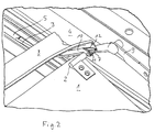
- Figure 1 shows the position of the parts essential to the invention when closed Cover 14 and closed sliding headliner 1.
- Headliner 1 in the area of its rear edge via a bracket 2 on one elongated, rail-like guide element 3 slidably held formed in the exemplary embodiment as a plastic rod coated with plastic.
- the guide element 3 has one relative to the vehicle roof 17 mounted section 5. This is followed by a flexible section 6 and a movable end 7.
- the cover 14 of the openable vehicle roof is only shown in FIG. 5, because he almost completely covers the drawn elements in the other figures would.
- the cover 14 is assigned a water channel 8, which may be in a ventilation gap released by the flared rear edge of the cover 14 Collect 16 penetrating water and into lateral water channels at Frame can derive.
- the water channel 8 moves with the lid 14 in its different positions.
- the movements of the lid 14 are from via a gate control that is partially recognizable in FIG. 1 on the right edge driven lever linkage 9 controlled, known and for that Invention is not essential.
- a control lever 10 is attached, which by the lever mechanism 9 driven movements of the water channel 8 participates.
- a driver 11 kept movable about a horizontal axis.
- the driver 11 remains in the outermost region of the movable end 7 of the guide element 3. Therefore, the guide element 3 slidably guided bracket 2 of the sliding headliner 1 with the sliding headliner 1 are moved along the guide element 3 until the holder 2 strikes against the driver 11 (which is the case in FIG. 2).
- the guide element forms 3 with its flexible transition area 6 between the Vehicle roof 17 parallel fixed area 5 and the movable End 7 depending on the position of the control lever 10 a differently shaped Train.
- When closed or on the way to the lid opening position displaced cover 14 is this path straight, so that the headliner 1 between the headliner opening position and one determined by striking the driver 11, in Fig. 1 the position corresponding to the sliding headliner closed position and can be moved here.
- This is done in this embodiment with the help of a recessed grip on the sliding headliner, not shown 1 manual, but can also be motorized.
- the end of the water channel facing away from the visible part of the control lever 10 8 is articulated to a guide shoe concealed in the figures, which runs along the mounting rails 4 is slidable and part of the movement mechanics of the lid 14 forms. It is immobile in a vertical direction.
- the edge of the lid that cannot be extended is also along the mounting rails 4 displaceable, but mounted immovable perpendicular to it. same for for the not shown front side of the headliner 1. On these details will not be discussed in more detail because they are not relevant to conventional differentiate openable vehicle roofs.
- a plastic spacer 13 recognizable in some figures is on the flexible transition region 6 facing end of the flag-like structure 12 attached and is supported when the movable end 7 is erected on the water channel 8 from. As a result, the path of the guide element 3 is additionally adjusted and also become rattling noises by hitting the water channel 8 avoided.
- the guide element 3 is, that is, inclusive over the entire area shown of sections 5, 6 and 7, integrally formed. It is preferably around a flexible steel rod or leaf spring encapsulated with plastic, the attachment to the vehicle roof in the area 5 via an injection molded Plastic mounting element is made.
- the metal bar has a circular one Cross section, so that the guide element 3 in the guiding Area has a spherical, partially circular cross-sectional profile. alternative the spherical guide area could also be formed by a plastic sheet be molded onto a metal leaf spring.
- Figures 1, 2 and 3 show that the lid Sliding headliner 1 during an opening movement from the closed position according to FIG. 1 and takes the sliding headliner 1 out of the Headliner deployment position towards the headliner opening position can be moved (from Fig. 2 to Fig. 3).
- Figure 3 does not show the full sliding headliner opening position because the movable bracket 2 would be moved out of the area shown, but only an intermediate stage in the movement there, i.e. a partially open one Position of the sliding roof 1.
- Fig. 4 shows, in comparison to Fig. 1, how the lid from the lid closed position 1 in the direction of the lid opening position can be.
- the lid 14 is slightly lowered to under actual vehicle roof 17 to be able to move what is in the Fig. 4 compared to Fig. 1 shows the flatter position of the lever linkage 9.
- the driver 11 is from the outermost region of the movable End 7 of the guide element 3 already slightly removed. You can also see that the driver 11 during this movement, the bracket 2 and thus the Can take sliding headliner 1, although in Fig. 4 for the sake of clarity no direct contact between driver 11 and bracket 2 is shown. Rather, in Fig. 4 the sliding headlining 1 is opposite to that due to the cover position forced position of the headliner 1 slightly further in the direction Headliner opening position shifted.
- Fig. 4 it can be seen that the movable end 7 is no longer held there and in particular the driver 11 has already reached the flexible area 6, so that the movable end 7 due to the flexibility of the flexible area 6 against a certain elasticity of the flexible area 6 is freely movable.
- at least the outermost region of the movable end 7 is magnetic.
- the steel rod contained in the guide element 3 is magnetic. It is preferably in the lowered position of the guide element 3 on one guide element holding device 18 designed as a permanent magnet held, arranged on a slidable in the mounting rail 4 and the movable end 7 in an elongated straight shape of the entire guide element 3 can hold corresponding position.
- the drive mechanism 9 of the cover can by the guide element holding device 18 forces exerted on the movable end 7 without overcome further and thus the positions shown in Figures 2 and 3 to reach.
Landscapes
- Engineering & Computer Science (AREA)
- Mechanical Engineering (AREA)
- Body Structure For Vehicles (AREA)
- Vehicle Interior And Exterior Ornaments, Soundproofing, And Insulation (AREA)
- Seal Device For Vehicle (AREA)
- Fittings On The Vehicle Exterior For Carrying Loads, And Devices For Holding Or Mounting Articles (AREA)
Abstract
Description
Die vorliegende Erfindung bezieht sich auf ein öffnungsfähiges Fahrzeugdach,
etwa für einen PKW oder ein Wohnmobil oder auch einen Wohnanhänger, gemäß
dem Oberbegriff des Patentanspruchs 1.The present invention relates to an openable vehicle roof,
for a car or a motorhome or a caravan, according to
the preamble of
Öffnungsfähige Fahrzeugdächer sind in den verschiedensten Ausführungsformen bekannt. In der Regel werden sie bei PKW eingesetzt, um die Belüftung des PKW-Innenraums zu verbessern. Dazu weisen öffnungsfähige Fahrzeugdächer generell einen Deckel auf, der eine Öffnung in dem Fahrzeugdach verschließen kann und aus dieser Deckelschließposition in eine Deckelausstellposition ausgestellt werden kann. In der Deckelausstellposition ist der Deckel gegenüber dem Fahrzeugdach an zumindest einer Seitenkante angehoben, so daß ein Lüftungsschlitz gebildet wird. Optional sind derartige Deckel meist zusätzlich über oder unter dem festen Dach nach hinten verschiebbar.Openable vehicle roofs are in a wide variety of designs known. They are usually used in cars to ventilate the vehicle To improve car interior. Openable vehicle roofs point to this generally a cover that closes an opening in the vehicle roof can and issued from this lid closing position in a lid opening position can be. In the cover opening position, the cover is opposite the Vehicle roof raised on at least one side edge, so that a ventilation slot is formed. Optionally, such covers are usually additionally over or slidable under the fixed roof.
Die Erfindung betrifft dabei ein öffnungsfähiges Fahrzeugdach mit einem Schiebehimmel, der den Deckel, beispielsweise einen transparenten Glasdeckel, in der Deckelschließposition zu dem Fahrzeuginnenraum hin abdecken kann und zudem dem Deckel in gewissem Umfang in die Deckelausstellposition folgen kann, also seinerseits in eine Schiebehimmelausstellposition mitbewegt werden kann. The invention relates to an openable vehicle roof with a sliding roof, of the lid, for example a transparent glass lid, in the Cover position to cover the vehicle interior and can also cover can follow the lid to a certain extent into the lid opening position, can in turn be moved into a sliding headliner display position.
Dadurch geben dann Deckel und Schiebehimmel gemeinsam einen Lüftungsschlitz frei.As a result, the cover and sliding headliner together provide a ventilation slot free.
Außerdem kann der Schiebehimmel, wie seine Bezeichnung bereits andeutet, aus der Schiebehimmelschließposition in dachparalleler Richtung seitlich in eine Schiebehimmelöffnungsposition verschoben werden, so daß der Deckel bzw. zumindest ein großer Teil des Deckels, von dem Schiebehimmel freigegeben wird. Dadurch läßt sich vom Fahrzeuginnenraum aus beispielsweise durch einen gläsernen Deckel die Umgebung betrachten und es verbessern sich die Lichtverhältnisse im Fahrzeuginnenraum.In addition, the sliding headlining, as its name suggests, from the sliding roof closing position in the roof parallel direction laterally into one Sliding headliner opening position so that the cover or at least a large part of the lid, released from the sliding headliner becomes. This allows, for example, a from the vehicle interior glass lid look at the surroundings and the lighting conditions improve in the vehicle interior.
Aus der DE 198 58 676 A1 ist ein öffnungsfähiges Fahrzeugdach bekannt, bei dem der Schiebehimmel hinsichtlich seiner Bewegung zwischen der Schiebehimmelschließposition und der Schiebehimmelöffnungsposition mit Hilfe eines langgestreckten Führungselements gehalten und geführt ist, entlang dem er verschiebbar ist. Die Besonderheit dieses öffnungsfähigen Fahrzeugdaches liegt daran, daß ein Teil des Führungselements bei der Bewegung des Schiebehimmels zwischen der Schiebehimmelausstellposition und der Schiebehimmelschließposition mitbewegt wird. Dabei handelt es sich um das Ende des Führungselements, das der auszustellenden Seite des Schiebehimmels und des Deckels zugeordnet ist. In einem von diesem Ende entfernten Bereich ist das Führungselement in bezüglich des Daches senkrechter Richtung unbeweglich gehalten. Die Beweglichkeit des Führungselements hat den Zweck, bei ausgestelltem Deckel eine Bewegung des Schiebehimmels zwischen der Schiebehimmelöffnungsposition und der Schiebehimmelausstellposition zu ermöglichen. Das Führungselement erfüllt seine Aufgabe also nicht nur bei geschlossenem Deckel, sondern auch im ausgestellten Zustand. Diese zusätzlichen Möglichkeiten haben sich in der Praxis bewährt und werden von den Benutzern gut angenommen. Die Lüftungsfunktion ist bei diesem öffnungsfähigen Fahrzeugdach gegenüber alternativen Ausführungsformen verbessert, bei denen der Schiebehimmel zur Herstellung eines Lüftungsschlitzes bei ausgestelltem Deckel ein Stück weit dachparallel verschoben werden muß oder für Lüftungszwecke eingebaute Lüftungsschlitze aufweist. Außerdem können die Fahrzeuginsassen die Ausstellposition des Deckels visuell besser wahrnehmen.An openable vehicle roof is known from DE 198 58 676 A1, at the sliding headliner in terms of its movement between the sliding headliner closed position and the sliding headliner opening position using a elongated guide element is held and guided, along which it is slidable is. The peculiarity of this openable vehicle roof lies remember that part of the guide element when moving the headliner between the sliding roof opening position and the sliding roof closing position is moved. This is the end of the guide element, that of the side of the sliding roof to be exhibited and the Lid is assigned. In an area distant from this end it is Guide element immovable in the direction perpendicular to the roof held. The mobility of the guide element has the purpose, when it is on display Cover a movement of the headliner between the headliner opening position and enable the sliding headliner display position. The Guide element does its job not only with the lid closed, but also in the exhibited state. Have these additional options proven in practice and well received by users. The The ventilation function of this openable vehicle roof is alternative Embodiments improved in which the sliding headliner for manufacturing of a ventilation slot with the cover open a little bit parallel to the roof must be moved or built-in ventilation slots for ventilation purposes having. In addition, the vehicle occupants can see the display position visually perceive the lid better.
Der Erfindung liegt die Aufgabe zugrunde, ein im Oberbegriff des Anspruchs 1
angegebenes öffnungsfähiges Fahrzeugdach im Hinblick auf die Führung des
Schiebehimmels zu verbessern.The invention is based, an object in the preamble of
Diese Aufgabe wird durch ein öffnungsfähiges Fahrzeugdach mit den Merkmalen
des Anspruchs 1 gelöst. Vorteilhafte Ausgestaltungen der Erfindung sind den
Unteransprüchen zu entnehmen.This task is accomplished through an openable vehicle roof with the characteristics
of
Die Erfindung besteht hierbei insbesondere darin, daß das Führungselement zumindest in einem Übergangsbereich zwischen einem unbeweglich gehaltenen Bereich und einem beweglichen Ende flexibel ist.The invention consists in particular in that the guide element at least in a transition area between a stationary one Area and a movable end is flexible.
Die Besonderheit des öffnungsfähigen Fahrzeugdaches besteht also darin, daß anstelle des bekannten mehrteiligen und zwischen diesen Teilen gelenkig ausgeführten Führungselements nun ein in dem Bereich zwischen dem (senkrecht zum Dach) unbeweglichen Bereich des Führungselements und dem beweglichen Ende flexibles, also biegbares, Führungselement verwendet wird. Durch die Flexibilität dieses Führungselementbereichs können die Gelenke des bekannten Führungselements ersetzt werden. Dadurch vereinfacht sich der Aufbau des Führungselements und somit auch des gesamten öffnungsfähigen Fahrzeugdaches mit entsprechenden damit verbundenen Kostenvorteilen. Zudem sind Gelenke im Hinblick auf Schmierung und Verschmutzungsempfindlichkeit wartungsbedürftige Bauteile, was für einen flexiblen Führungselementbereich bei geeigneter Materialwahl nicht gilt.The peculiarity of the openable vehicle roof is therefore that instead of the known multi-part and articulated between these parts Guide element now in the area between the (perpendicular to the roof) immovable area of the guide element and the movable End flexible, so bendable, guide element is used. Because of the flexibility this guide element area can the joints of the known Guide element to be replaced. This simplifies the construction of the guide element and therefore also the entire openable vehicle roof with corresponding associated cost advantages. In addition, joints are in the With regard to lubrication and sensitivity to contamination, maintenance is required Components, what a flexible guide element area with a suitable choice of materials does not apply.
In Bezug auf den Wortlaut des Anspruchs 1 ist klarzustellen, daß sich der Begriff
des "großen Teils", der durch den in die Schiebehimmelöffnungsposition bewegten
Schiebehimmel freigegeben werden kann, auf das Format eines Schiebehimmels
bzw. eines Deckels bezieht. Bei öffnungsfähigen Fahrzeugdächern mit
mehreren kombinierten Deckeln kann dies u.U. weniger als der größte Teil der
Dachöffnung sein. Es sind auch öffnungsfähige Fahrzeugdächer denkbar, bei
denen mehrere Schiebehimmel vorgesehen sind, wobei die vorstehenden Aussagen
für einen der Schiebehimmel, vorzugsweise für alle Schiebehimmel gelten.
Auch dann bezieht sich der Begriff "großen Teils" auf das Format des einzelnen
Schiebehimmelteils.With regard to the wording of
In der Regel sind öffnungsfähige Fahrzeugdächer so aufgebaut, daß der Deckel an genau einer Seite gegenüber dem Dach angehoben werden kann und an der gegenüberliegenden Seite im wesentlichen auf Dachniveau liegen bleibt. Dabei soll der Schiebehimmel an der der auszustellenden Seite des Deckels zugeordneten Seite ausgestellt werden. Die Erfindung bezieht sich jedoch auch auf andere Varianten, etwa auf mit allen Seiten ausstellbare Deckel. Die erfindungsgemäße Führungselementkonstruktion muß dabei an zumindest einer Seite des Schiebehimmels vorgesehen sein.As a rule, openable vehicle roofs are constructed so that the cover can be lifted on exactly one side opposite the roof and on the opposite side remains essentially at roof level. there the sliding headliner is to be assigned to the side of the cover to be exhibited Side will be issued. However, the invention also relates to others Variants, such as lids that can be opened on all sides. The invention Guide element construction must be on at least one side of the headliner be provided.
Die Bewegungen des Deckels und des Schiebehimmels können von Hand oder motorisch erfolgen. Hierauf wird nicht näher eingegangen, weil die verschiedenen in Frage kommenden Varianten und Antriebstechniken dem Fachmann vertraut sind und mit der Erfindung in keiner engen Beziehung stehen. Bevorzugt ist jedoch, daß die Bewegung des Schiebehimmels aus der Schiebehimmelschließposition in die -ausstellposition durch die entsprechende Bewegung des Deckels erfolgt, der Schiebehimmel also mit dem Deckel mitgenommen wird. Dies gilt natürlich nur für die Situation, in der der Schiebehimmel zuvor in der Schiebehimmelschließposition war. Wenn er zuvor in der Schiebehimmelöffnungsposition war, so ist er vorzugsweise von der Bewegung des Deckels in die Ausstellposition entkoppelt. The movements of the cover and the sliding headliner can be done by hand or done by motor. This will not be discussed in more detail because of the different possible variants and drive technologies familiar to the expert are and are not closely related to the invention. However, it is preferred that the movement of the headliner from the headliner closing position in the opening position by the corresponding movement of the cover takes place, so the headliner is taken along with the lid. Of course this applies only for the situation in which the headliner was previously in the headliner closing position was. If he was previously in the sunroof opening position was, it is preferably from the movement of the lid into the opening position decoupled.
Ein wesentlicher Vorteil der Erfindung besteht darin, daß sich durch die flexible Ausführung des Übergangsbereichs zwischen (senkrecht zum Dach) unbeweglichem Bereich des Führungselements und dem beweglichen Ende eine einstückige Ausführung des Führungselements erreichen läßt. Dadurch kann das Führungselement besonders einfach und montagegünstig aufgebaut sein. Zumindest der Bereich des Führungselements, in dem die den Schiebehimmel an dem Führungselement haltende Halterung verschoben werden kann, ist vorzugsweise einstückig ausgeführt. Dies hat den Vorteil einer weitgehenden Vermeidung von Geräuschen bei den Bewegungsabläufen, mit denen sich die verschiebbare Halterung entlang dem Führungselement bewegt, und zwar insbesondere von diskontinuierlichen Geräuschen. Solche Geräusche sind bei mehrteiligen Führungselementen und Übergängen zwischen den Teilen kaum zu vermeiden und erwecken beim Benutzer den Eindruck, daß das Dach "klappert" und möglicherweise ein Defekt oder zumindest lose Teile zu befürchten sind. Demgegenüber stören die bei Verschiebungen möglicherweise auftretenden Schleif- oder Rollgeräusche weniger. An dieser Stelle ist anzumerken, daß die verschiebbare Halterung entlang dem Führungselement auch durch ein Abrollen verschiebbar sein könnte, im einfacheren und bevorzugten Fall jedoch gleitet.A major advantage of the invention is that the flexible Execution of the transition area between (perpendicular to the roof) immovable Area of the guide element and the movable end of a one-piece Execution of the guide element can be achieved. This allows the guide element be particularly simple and easy to assemble. At least the area of the guide element in which the sliding headliner on the guide element holding bracket can be moved, is preferably in one piece executed. This has the advantage of largely avoiding noise in the movements with which the sliding bracket moved along the guide element, in particular discontinuous Noise. Such noises are in multi-part guide elements and transitions between the parts can hardly be avoided and awaken the user the impression that the roof "rattles" and possibly a Defective or at least loose parts are to be feared. In contrast, they disturb in the event of shifts, grinding or rolling noises may occur fewer. At this point it should be noted that the sliding bracket along the guide element could also be displaceable by rolling, in simpler and preferred case, however, slides.
Die Führung des Schiebehimmels über die erwähnte verschiebbare Halterung an dem Führungselement kann hinsichtlich der Formgestaltung der beteiligten Elemente in unterschiedlichster Weise gelöst werden. Bevorzugt ist bei dieser Erfindung jedoch, daß das Führungselement ein balliges Querschnittsprofil aufweist. Dabei umfasst der Begriff "ballig" auch polygonale eckige Profile und auch Teile im übrigen nicht balliger Profile wie etwa den Querbalken bei einem T-Profil. Dieses Profil kann von einer geeigneten Halterung umgriffen werden, so daß diese entlang des Profils verschoben werden kann. Im einfachsten Fall handelt es sich um ein zumindest teilweise kreisförmiges Querschnittsprofil. Ein konkaves Querschnittsprofil des Führungselements ist allerdings auch möglich. Jedenfalls muß eine Führung in den zu der Verschieberichtung senkrechten Richtungen gegeben sein. The guidance of the sliding headliner on the aforementioned movable bracket the guide element can with regard to the design of the elements involved be solved in different ways. Is preferred in this invention however, that the guide element has a spherical cross-sectional profile. The term "spherical" also includes polygonal angular profiles and also parts otherwise non-spherical profiles such as the crossbar in a T-profile. This Profile can be gripped by a suitable holder, so that this can be moved along the profile. In the simplest case it is around an at least partially circular cross-sectional profile. A concave cross-sectional profile the guide element is also possible. In any case, must given a guide in the directions perpendicular to the direction of displacement his.
Ferner ist das Führungselement jedenfalls in dem flexiblen Übergangsbereich vorzugsweise als flexible Metallstange ausgestaltet (die im einfachsten Fall das erwähnte ballige Querschnittsprofil aufweist).Furthermore, the guide element is in any case in the flexible transition area preferably designed as a flexible metal rod (in the simplest case that has mentioned spherical cross-sectional profile).
Das bewegbare Ende des Führungselements kann versteift sein, so daß die flexiblen Eigenschaften, die etwa infolge einer einstückigen Ausführung mit dem flexiblen Übergangsbereich sonst vorhanden wären, durch die Versteifung aufgehoben werden. Dadurch kann eine fest vorgegebene Form des bewegbaren Endes definiert werden, die bei den verschiedenen Bewegungsabläufen erhalten bleibt. Beispielsweise kann eine gerade Form des bewegbaren Endes über eine bestimmte Strecke vorgegeben werden, die in der Schiebehimmel-Ausstellposition so schräg steht, daß sie den Anstieg der betreffenden Seite des Schiebehimmels in die Schiebehimmel-Ausstellposition vorgibt, wenn diese aus der Schiebehimmel-Öffnungsposition dorthin verschoben wird. Der Übergang von dieser schrägstehenden geraden Strecke in einen im übrigen im wesentlichen zum Fahrzeugdach parallel laufenden Bereich des Führungselements kann dann durch den flexiblen Übergangsbereich bewerkstelligt sein.The movable end of the guide element can be stiffened so that the flexible Properties that are due to a one-piece design with the flexible transition area would otherwise exist, canceled out by the stiffening become. This allows a fixed predetermined shape of the movable end be defined, which are obtained in the different movement sequences remains. For example, a straight shape of the movable end over a certain distance can be specified in the sliding headliner display position stands so obliquely that the rise of the relevant side of the Sliding headliner in the sliding headliner deployment position specifies when this the sliding headliner opening position is moved there. The transition from this inclined straight line into one essentially area of the guide element running parallel to the vehicle roof can then be accomplished through the flexible transition area.
Beispielsweise kann die erwähnte Metallstange als Walzprofil hergestellt werden, das neben einem balligen, für sich genommen flexiblen Querschnittsprofilanteil einen weiteren versteifenden Querschnittsprofilanteil aufweist, etwa ein seitliches "Fähnchen". Der versteifende Querschnittsprofilanteil kann dann durch Freistanzen oder anderweitig an bestimmten Stellen entfernt werden, um eine Trennung zwischen dem flexiblen Übergangsbereich und dem erwähnten versteiften Abschnitt des bewegbaren Endes herzustellen. Der versteifende Querschnittsprofilanteil kann beispielsweise auch zur Befestigung des unbeweglichen Abschnitts des Führungselements dienen.For example, the metal rod mentioned can be produced as a rolled profile, in addition to a convex, flexible cross-sectional profile component has a further stiffening cross-sectional profile portion, such as a lateral one "Flag". The stiffening cross-sectional profile portion can then be punched out or otherwise removed in certain locations to create a separation between the flexible transition area and the stiffened section mentioned of the movable end. The stiffening cross-sectional profile portion can also be used, for example, to attach the immovable section serve the guide element.
Zur Verbesserung der Gleiteigenschaften kann das Führungselement mit einer Kunststoffbeschichtung versehen sein. Dabei kann die Kunststoffbeschichtung auch zur Versteifung beitragen. Der Kunststoff kann an das Führungselement angespritzt sein. Der Kunststoff kann auch ausschließlich für die Führungseigenschaften verantwortlich sein, während ein Metallteil oder Metallkern, etwa eine Blattfeder, lediglich zur Festlegung der flexiblen Eigenschaften beiträgt.To improve the sliding properties, the guide element can be used with a Be plastic coating. The plastic coating also contribute to stiffening. The plastic can be attached to the guide element be injected. The plastic can also be used exclusively for the guiding properties be responsible while a metal part or core, such as a Leaf spring, only contributes to the determination of the flexible properties.
Bei der bereits erwähnten Variante, bei der der Deckel in eine Deckel-Öffnungsposition bewegbar ist, ist in der Regel erwünscht, daß der Schiebehimmel bei der Bewegung des Deckels in die Deckel-Öffnungsposition mitgenommen wird. Dies kann bei der vorliegenden Erfindung vorzugsweise dadurch geschehen, daß der Deckel über einen Mitnehmer mit dem Führungselement verbunden ist, der auf der dem bewegbaren Ende zugewandten Seite der verschiebbaren Halterung des Schiebehimmels liegt, so daß er bei einer Bewegung des Deckels in Richtung zu der Deckel-Öffnungsposition an diese Halterung anschlägt und dadurch den Schiebehimmel in diese Richtung mitnimmt. Der Schiebehimmel sollte dabei soweit mitgenommen werden, daß er im wesentlichen den durch den Deckel geöffneten Teil der Dachöffnung freigibt.In the variant already mentioned, in which the lid is in a lid opening position is movable, it is usually desirable that the sliding headliner taken into the lid opening position when the lid is moved becomes. In the present invention, this can preferably be done by that the lid is connected to the guide element via a driver is that on the side of the movable end facing the movable end Bracket of the sliding headliner is so that it moves when the cover strikes against this bracket towards the lid opening position and thereby taking the headliner in this direction. The sliding roof should be taken along so far that it is essentially the Part of the roof opening opened.
Die Bewegung des Deckels von der Deckel-Schließposition in die Deckel-Ausstellposition soll ebenfalls vorzugsweise den Schiebehimmel in die SchiebehimmelAusstellposition mitnehmen, wenn er zuvor in der Schiebehimmel-Schließposition war. Dazu kann vorgesehen sein, daß der erwähnte Mitnehmer so mit dem Deckel bzw. einer Einrichtung zum Ausstellen des Deckels gekoppelt ist, daß er bei der Bewegung in die Deckel-Ausstellposition das bewegliche Ende des Führungselements mitnimmt und dadurch, d.h. über die erwähnte verschiebbare Halterung des Schiebehimmels, auch den Schiebehimmel.The movement of the lid from the lid closing position to the lid opening position should also preferably slide the headliner into the sliding headliner deployment position take it with you if it is in the sliding headliner closed position was. For this purpose it can be provided that the driver mentioned thus coupled with the lid or a device for opening the lid is that it moves the movable end when moving to the cover opening position of the guide element and thereby, i.e. about the mentioned sliding Bracket for the sliding roof, including the sliding roof.
Eine Möglichkeit besteht darin, daß der Mitnehmer an einem Steuerhebel einer an sich bekannten Wasserrinne angebracht oder mit diesem gekoppelt ist, der mit der Ausstellbewegung des Deckels gekoppelt ist. One possibility is that the driver on a control lever attached to known water channel or coupled to this, which with the opening movement of the lid is coupled.
Schon in Verbindung mit der erwähnten Einstückigkeit des Führungselements in dem von der Halterung erfaßbaren Bereich wurde erläutert, daß Geräuscharmut ein wesentliches Gütemerkmal des erfindungsgemäßen Ausstelldaches sein kann. Ein weiterer Aspekt der Geräuscharmut betrifft das bewegliche Ende des Führungselements, und zwar in solchen Situationen, in denen dieses nicht anderweitig gehalten wird. Beispielsweise wird es bei den zuvor erläuterten Varianten durch den mit dem Deckel gekoppelten Mitnehmer gehalten, wenn sich der Deckel in der Deckel-Ausstellposition oder der Deckel-Schließposition befindet. Wenn er sich jedoch in der Deckel-Öffnungsposition befindet, ist der Mitnehmer entlang dem Führungselement von dem beweglichen Ende weg verschoben, so daß dieses Klappergeräusche verursachen könnte, wenn es frei beweglich bleibt. Hier ist vorzugsweise vorgesehen, eine Halteeinrichtung für das Führungselement anzubringen, die eine zu Geräuschen führende freie Beweglichkeit unterbindet. Dies kann beispielsweise ein Magnet sein, der einen magnetischen Teil des beweglichen Endes des Führungselements halten kann. Dadurch kann der Mitnehmer das bewegliche Ende auch ohne weiteres lösen, wenn dieses in die Ausstellposition mitgenommen werden soll.Already in connection with the mentioned one-piece design of the guide element in the area covered by the bracket was explained that low noise be an essential quality feature of the pop-up roof according to the invention can. Another aspect of low noise is the moving end of the Leadership element, in situations where this is not otherwise is held. For example, it will be in the previously explained variants held by the driver coupled to the lid when the Lid is in the lid opening position or the lid closing position. However, when it is in the lid open position, the driver is shifted away from the movable end along the guide element, so that this could cause rattling noises if it remains freely movable. A holding device for the guide element is preferably provided here to be attached, which prevents a free mobility leading to noise. This can be a magnet, for example, which is a magnetic part the movable end of the guide element can hold. This allows the Take away the movable end without further ado if this is in the Exhibition position should be taken.
Im folgenden wird ein konkretes Ausführungsbeispiel der Erfindung anhand der Zeichnung näher erläutert. Es zeigt:
- Fig. 1
- eine Teilansicht eines Fahrzeugdaches in perspektivischer Ansicht, wobei der Deckel weggelassen ist, in der Deckel-Schließposition und der Schiebehimmel-Schließposition;
- Fig. 2
- eine Teilansicht analog zur Fig. 1 in der Deckel-Ausstellposition und der Schiebehimmel-Ausstellposition;
- Fig. 3
- eine Teilansicht analog zur Fig. 1 in der Deckel-Ausstellposition und mit einem ein Stück weit in Richtung zur Schiebehimmel-Öffnungsposition zurückgeschobenen Schiebehimmel;
- Fig. 4
- eine Teilansicht analog zur Fig. 1 in einer Situation, in der der Deckel ein Stück weit in Richtung Deckelöffnungsposition und der Schiebehimmel ein Stück weit in Richtung Schiebehimmelöffnungsposition verschoben ist; und
- Fig. 5
- einen Teil-Längsschnitt durch den hinteren Teil des Fahrzeugdachs in einer Position gemäß Fig. 2.
- Fig. 1
- a partial view of a vehicle roof in a perspective view, with the lid omitted, in the lid-closed position and the sliding headliner-closed position;
- Fig. 2
- a partial view similar to Figure 1 in the cover opening position and the sliding headliner opening position.
- Fig. 3
- a partial view analogous to Figure 1 in the cover opening position and with a sliding headliner pushed back a little towards the sliding roof opening position;
- Fig. 4
- a partial view analogous to Figure 1 in a situation in which the lid is a little bit towards the lid opening position and the sliding headliner is slightly shifted towards the sliding headlining position. and
- Fig. 5
- 3 shows a partial longitudinal section through the rear part of the vehicle roof in a position according to FIG. 2.
Die Figur 1 zeigt die Position der für die Erfindung wesentlichen Teile bei geschlossenem
Deckel 14 und geschlossenem Schiebehimmel 1. Dabei ist der
Schiebehimmel 1 im Bereich seiner Hinterkante über eine Halterung 2 an einem
langgestreckten, schienenartigen Führungselement 3 verschiebbar gehalten, das
im Ausführungsbeispiel als eine mit Kunststoff beschichtete Metallstange ausgebildet.
Das Führungselement 3 weist einen relativ zum Fahrzeugdach 17 fest
montierten Abschnitt 5 auf. An diesen schließt sich ein flexibler Abschnitt 6 an
sowie ein bewegliches Ende 7.Figure 1 shows the position of the parts essential to the invention when closed
Der Deckel 14 des öffnungsfähigen Fahrzeudaches ist nur in Fig. 5 dargestellt,
weil er in den übrigen Figuren die gezeichneten Elemente fast vollständig verdekken
würde. Dem Deckel 14 ist eine Wasserrinne 8 zugeordnet, die eventuell in
einen durch die ausgestellte Hinterkante des Deckels 14 freigegebenen Lüftungsspalt
16 eindringendes Wasser auffangen und in seitliche Wasserrinnen am
Rahmen ableiten kann. Die Wasserrinne 8 bewegt sich mit dem Deckel 14 in
dessen verschiedene Positionen. Die Bewegungen des Deckels 14 werden von
einem über eine in Figur 1 am rechten Rand ansatzweise erkennbare Kulissensteuerung
angetriebenen Hebelgestänge 9 gesteuert, das bekannt und für die
Erfindung nicht wesentlich ist.The
An der Wasserrinne 8 ist ein Steuerhebel 10 befestigt, der die durch die Hebelmechanik
9 angetriebenen Bewegungen der Wasserrinne 8 mitmacht. An dem
von der Wasserrinne entfernten Ende des Steuerhebels 10 ist ein Mitnehmer 11
um eine horizontale Achse beweglich gehalten. Durch die Bewegung der Wasserrinne
8 wird über den Steuerhebel 10 und den Mitnehmer 11 das bewegbare Ende
7 des Führungselements 3 bei der Bewegung in die Ausstellposition des Dekkels
14 mitgenommen, wie insbesondere aus den Fign. 2 und 3 erkennbar ist.
Dabei bleibt der Mitnehmer 11 im äußersten Bereich des bewegbaren Endes 7
des Führungselements 3. Daher kann die ebenfalls an dem Führungselement 3
verschiebbar geführte Halterung 2 des Schiebehimmels 1 mit dem Schiebehimmel
1 entlang des Führungselements 3 verschoben werden, bis die Halterung 2
an den Mitnehmer 11 anschlägt (was in Fig. 2 der Fall ist). Dabei bildet das Führungselement
3 mit seinem flexiblen Übergangsbereich 6 zwischen dem zum
Fahrzeugdach 17 parallel verlaufenden fest montierten Bereich 5 und dem bewegbaren
Ende 7 je nach Lage des Steuerhebels 10 eine unterschiedlich geformte
Bahn. Bei geschlossenem oder auf dem Weg in die Deckel-Öffnungsposition
verschobenem Deckel 14 (vgl. Fig 1 und Fig. 4) ist diese Bahn
gerade, so daß der Schiebehimmel 1 zwischen der Schiebehimmel-Öffnungsposition
und einer durch das Anschlagen an den Mitnehmer 11 bestimmten,
in Fig. 1 der Schiebehimmel-Schließposition entsprechenden Lage hin
und her verschoben werden kann. Dies erfolgt bei diesem Ausführungsbeispiel
mit Hilfe einer nicht dargestellten innenraumseitigen Griffmulde am Schiebehimmel
1 manuell, kann jedoch auch motorisiert ablaufen.On the
Das dem sichtbaren Teil des Steuerhebels 10 abgewandte Ende des Wasserrinne
8 ist an einem in den Figuren verdeckten Führungsschuh angelenkt, der entlang
der Montageschienen 4 verschiebbar ist und einen Teil der Bewegungsmechanik
des Deckels 14 bildet. Er ist in senkrechter Richtung unbeweglich. Die
nicht auszustellende Kante des Deckels ist ebenfalls entlang der Montageschienen
4 verschieblich, jedoch senkrecht dazu unbeweglich gelagert. Gleiches gilt
für die nicht dargestellte vordere Seite des Schiebehimmels 1. Auf diese Einzelheiten
wird nicht näher eingegangen, weil sie sich nicht relevant von konventionellen
öffnungsfähigen Fahrzeugdächern unterscheiden. The end of the water channel facing away from the visible part of the
Bei durch Ausstellung des Deckels 14 schräg aufgestelltem Steuerhebel 10 ist
der flexible Bereich 6 des Führungselements 3 gekrümmt, wie die Fign. 2 und 3
zeigen. Das bewegbare Ende 7 bleibt dabei gerade, und zwar infolge einer Versteifung
durch eine in diesem Bereich auf der dem Steuerhebel 10 abgewandten
Seite des Führungselements 3 angebrachten fähnchenartigen Struktur 12. Hierbei
handelt es sich um ein mit einer Kunststoffbeschichtung versehenes, vorzugsweise
angespritztes Kunststoffteil.When the
Ein in einigen Figuren erkennbarer Kunststoffabstandhalter 13 ist an dem dem
flexiblen Übergangsbereich 6 zugewandten Ende der fähnchenartigen Struktur 12
angebracht und stützt sich bei Aufrichtung des bewegbaren Endes 7 an der Wasserrinne
8 ab. Dadurch wird die Bahn des Führungselements 3 zusätzlich eingestellt
und werden außerdem Klappergeräusche durch Anschlagen an die Wasserrinne
8 vermieden.A
Das Führungselement 3 ist über den gesamten dargestellten Bereich, also einschließlich
der Abschnitte 5, 6 und 7, einstückig ausgebildet. Es handelt sich vorzugsweise
um eine mit Kunststoff umspritzte flexible Stahlstange oder Blattfeder,
wobei die Befestigung an dem Fahrzeugdach in dem Bereich 5 über ein angespritztes
Kunststoffmontageelement erfolgt. Die Metallstange hat einen kreisförmigen
Querschnitt, so dass das Führungselement 3 in dem der Führung dienenden
Bereich ein balliges, teilweise kreisförmiges Querschnittsprofil aufweist. Alternativ
könnte der ballige Führungsbereich auch durch eine Kunststoffbahn gebildet
sein, die etwa an eine Metallblattfeder angespritzt ist.The
Zusammenfassend zeigen also die Figuren 1, 2 und 3, daß der Deckel den
Schiebehimmel 1 bei einer Ausstellbewegung von der Schließposition gemäß Fig.
1 in die Ausstellposition gemäß Fig. 2 mitnimmt und der Schiebehimmel 1 aus der
Schiebehimmel-Ausstellposition in Richtung zu der Schiebehimmel-Öffnungsposition
verschoben werden kann (von Fig. 2 nach Fig. 3). Die Figur 3
zeigt dabei nicht die vollständige Schiebehimmel-Öffnungsposition, weil dabei die
verschiebbare Halterung 2 aus dem abgebildeten Bereich herausbewegt wäre,
sondern lediglich eine Zwischenstufe in der Bewegung dorthin, also eine teilgeöffnete
Position des Schiebehimmels 1.In summary, Figures 1, 2 and 3 show that the
Fig. 4 zeigt wiederum im Vergleich zu Fig. 1, wie der Deckel aus der Deckelschließposition
in Fig. 1 in Richtung zu der Deckel-Öffnungsposition verschoben
werden kann. Dabei wird zunächst der Deckel 14 etwas abgesenkt, um unter dem
eigentlichen Fahrzeugdach 17 verschoben werden zu können, was sich an der in
Fig. 4 gegenüber Fig. 1 flacheren Stellung des Hebelgestänges 9 erkennen läßt.
Außerdem ist der Mitnehmer 11 von dem äußersten Bereich des bewegbaren
Endes 7 des Führungselements 3 bereits etwas entfernt. Man erkennt außerdem,
daß der Mitnehmer 11 bei dieser Bewegung die Halterung 2 und damit den
Schiebehimmel 1 mitnehmen kann, wenngleich in Fig. 4 der Übersichtlichkeit halber
keine direkte Anlage zwischen Mitnehmer 11 und Halterung 2 gezeichnet ist.
Vielmehr ist in Fig. 4 der Schiebehimmel 1 gegenüber der durch die Deckelposition
erzwungenen Position des Schiebehimmels 1 geringfügig weiter in Richtung
Schiebehimmel-Öffnungsposition verschoben.Fig. 4 shows, in comparison to Fig. 1, how the lid from the lid closed
In Fig. 4 erkennt man, daß dort das bewegbare Ende 7 nicht mehr gehalten ist
und insbesondere der Mitnehmer 11 bereits den flexiblen Bereich 6 erreicht hat,
so daß das bewegbare Ende 7 infolge der Flexibilität des flexiblen Bereichs 6 gegen
eine gewisse Elastizität des flexiblen Bereichs 6 frei beweglich ist. Um hierbei
Klappergeräusche etwa beim Überfahren von Bodenunebenheiten zu vermeiden,
ist zumindest der äußerste Bereich des bewegbaren Endes 7 magnetisch. Vorzugsweise
ist die in dem Führungselement 3 enthaltene Stahl-stange magnetisch.
Sie wird in abgesenkter Position des Führungselements 3 an einer vorzugsweise
als Dauermagnet ausgebildeten Führungselement-Halteeinrichtung 18
gehalten, die an einem in der Montageschiene 4 verschiebbaren Gleiter angeordnet
ist und das bewegliche Ende 7 in einer einer langgestreckten geraden Form
des gesamten Führungselements 3 entsprechenden Position festhalten kann. In Fig. 4 it can be seen that the
Andererseits kann die Antriebsmechanik 9 des Deckels die durch die Führungselement-Halteeinrichtung
18 auf das bewegbare Ende 7 ausgeübten Kräfte ohne
weiteres überwinden und damit die in den Figuren 2 und 3 dargestellten Positionen
erreichen. On the other hand, the
- 11
- Schiebehimmelsliding sky
- 22
- Halterungbracket
- 33
- Führungselementguide element
- 44
- Montageschienenmounting rails
- 55
- Bereich von 3 (fest montiert)Range of 3 (fixed)
- 66
- Übergangsbereich von 3 (flexibel)Transition area of 3 (flexible)
- 77
- Ende von 3 (bewegliches)End of 3 (movable)
- 88th
- Wasserrinnegully
- 99
- Hebelmechaniklever mechanism
- 1010
- Steuerhebelcontrol lever
- 1111
- Mitnehmertakeaway
- 1212
- Strukturstructure
- 1313
- KunststoffabstandshalterPlastic spacers
- 1414
- Deckelcover
- 1515
- Dachöffnungroof opening
- 1616
- Lüftungsspaltventilation gap
- 1717
- Fahrzeugdachvehicle roof
- 1818
- Führungselement-HalteeinrichtungGuide member support means
Claims (11)
dadurch gekennzeichnet, dass das Führungselement (3) in den von der verschiebbaren Halterung (2) erfaßbaren Bereichen (5, 6, 7) einstückig ausgebildet ist.Openable vehicle roof according to claim 1,
characterized in that the guide element (3) is formed in one piece in the regions (5, 6, 7) which can be detected by the displaceable holder (2).
dadurch gekennzeichnet, dass eine Führungsbahn des Führungselements (3) ein balliges Querschnittsprofil aufweist.Openable vehicle roof according to one of the preceding claims,
characterized in that a guideway of the guide element (3) has a spherical cross-sectional profile.
dadurch gekennzeichnet, dass zumindest der Übergangsbereich (6) des Führungselements (3) von einer flexiblen Metallstange oder von einer metallenen Blattfeder gebildet wird.Openable vehicle roof according to one of the preceding claims,
characterized in that at least the transition region (6) of the guide element (3) is formed by a flexible metal rod or by a metal leaf spring.
dadurch gekennzeichnet, dass das Führungselement (3) kunststoffbeschichtet ist.Openable vehicle roof according to one of claims 1 to 4,
characterized in that the guide element (3) is plastic-coated.
dadurch gekennzeichnet, dass das bewegbare Ende (7) des Führungselements (3) über einen Längenabschnitt (12) versteift ist.Openable vehicle roof according to one of the preceding claims,
characterized in that the movable end (7) of the guide element (3) is stiffened over a length section (12).
dadurch gekennzeichnet, dass der Deckel (14) in eine Deckel-Öffnungsposition bewegbar ist, in der er einen großen Teil der Dachöffnung (15) freigibt und den Schiebehimmel (1) über einen an dem Führungselement (3) geführten und bei einer Bewegung in die Dachöffnungsposition an die verschiebbare Halterung (2) anschlagenden Mitnehmer (11) in die Schiebehimmel-Öffnungsposition mitnimmt.Openable vehicle roof according to one of the preceding claims,
characterized in that the cover (14) can be moved into a cover opening position, in which it opens a large part of the roof opening (15) and the sliding headliner (1) is guided by a guide element (3) and when it moves into the Carries roof opening position on the sliding bracket (2) driving driver (11) in the sliding headliner opening position.
dadurch gekennzeichnet, dass der Mitnehmer (11) mit einer Einrichtung (Hebelmechanik 9) zum Ausstellen des Deckels (14) gekoppelt ist und das bewegliche Ende (7) des Führungselements (3) bei einer Bewegung des Deckels (14) in die Deckel-Ausstellposition mitnimmt.Openable vehicle roof according to claim 7,
characterized in that the driver (11) is coupled to a device (lever mechanism 9) for opening the cover (14) and the movable end (7) of the guide element (3) when the cover (14) moves into the cover opening position entraining.
dadurch gekennzeichnet, dass der Mitnehmer (11) an einem mit der Einrichtung (9) zum Ausstellen des Deckels (14) gekoppelten Steuerhebel (10) einer Wasserrinne (8) befestigt ist.Openable vehicle roof according to claim 7 or 8,
characterized in that the driver (11) is attached to a control lever (10) of a water channel (8) coupled to the device (9) for opening the cover (14).
dadurch gekennzeichnet, dass eine dachfest angeordnete Führungselement-Halteeinrichtung (18) zum Halten des beweglichen Endes des Führungselements (3) vorgesehen ist.Openable vehicle roof according to one of the preceding claims,
characterized in that a roof-mounted guide element holding device (18) is provided for holding the movable end of the guide element (3).
dadurch gekennzeichnet, dass die Führungselement-Halteeinrichtung (18) von einem Magneten gebildet ist und das bewegliche Ende (7) des Führungselements (3) zumindest teilweise magnetisch ausgebildet ist.Openable vehicle roof according to claim 10,
characterized in that the guide element holding device (18) is formed by a magnet and the movable end (7) of the guide element (3) is at least partially magnetic.
Applications Claiming Priority (2)
| Application Number | Priority Date | Filing Date | Title |
|---|---|---|---|
| DE10131885A DE10131885C2 (en) | 2001-07-04 | 2001-07-04 | Openable vehicle roof with improved sliding headlining element |
| DE10131885 | 2001-07-04 |
Publications (3)
| Publication Number | Publication Date |
|---|---|
| EP1273469A2 true EP1273469A2 (en) | 2003-01-08 |
| EP1273469A3 EP1273469A3 (en) | 2003-05-07 |
| EP1273469B1 EP1273469B1 (en) | 2008-01-02 |
Family
ID=7690246
Family Applications (1)
| Application Number | Title | Priority Date | Filing Date |
|---|---|---|---|
| EP02014533A Expired - Lifetime EP1273469B1 (en) | 2001-07-04 | 2002-07-01 | Open roof for vehicle with improved guiding element for the sliding headliner |
Country Status (4)
| Country | Link |
|---|---|
| US (1) | US6726274B2 (en) |
| EP (1) | EP1273469B1 (en) |
| JP (1) | JP2003034144A (en) |
| DE (2) | DE10131885C2 (en) |
Cited By (1)
| Publication number | Priority date | Publication date | Assignee | Title |
|---|---|---|---|---|
| EP1288041A2 (en) * | 2001-08-30 | 2003-03-05 | Webasto Vehicle Systems International GmbH | Sliding roof arrangement with sliding screen |
Families Citing this family (1)
| Publication number | Priority date | Publication date | Assignee | Title |
|---|---|---|---|---|
| DE20213653U1 (en) * | 2002-09-04 | 2004-02-12 | Inalfa Industries B.V. | Roof assembly for a vehicle |
Citations (1)
| Publication number | Priority date | Publication date | Assignee | Title |
|---|---|---|---|---|
| DE19858676A1 (en) | 1998-12-18 | 2000-06-29 | Webasto Vehicle Sys Int Gmbh | Openable vehicle roof with adjustable headlining |
Family Cites Families (3)
| Publication number | Priority date | Publication date | Assignee | Title |
|---|---|---|---|---|
| DE8107603U1 (en) * | 1981-03-16 | 1981-08-20 | Schlapp, Albert, 6072 Dreieich | DEVICE ON A SLIDING COVER FOR MOTOR VEHICLES |
| DE3740129A1 (en) * | 1987-11-26 | 1989-06-08 | Webasto Ag Fahrzeugtechnik | SLIDING ROOF FOR VEHICLES |
| JPH11222037A (en) * | 1998-02-03 | 1999-08-17 | Toyota Motor Corp | Vehicle with sun roof |
-
2001
- 2001-07-04 DE DE10131885A patent/DE10131885C2/en not_active Expired - Fee Related
-
2002
- 2002-07-01 DE DE50211443T patent/DE50211443D1/en not_active Expired - Lifetime
- 2002-07-01 EP EP02014533A patent/EP1273469B1/en not_active Expired - Lifetime
- 2002-07-02 US US10/187,426 patent/US6726274B2/en not_active Expired - Lifetime
- 2002-07-04 JP JP2002196451A patent/JP2003034144A/en active Pending
Patent Citations (1)
| Publication number | Priority date | Publication date | Assignee | Title |
|---|---|---|---|---|
| DE19858676A1 (en) | 1998-12-18 | 2000-06-29 | Webasto Vehicle Sys Int Gmbh | Openable vehicle roof with adjustable headlining |
Cited By (1)
| Publication number | Priority date | Publication date | Assignee | Title |
|---|---|---|---|---|
| EP1288041A2 (en) * | 2001-08-30 | 2003-03-05 | Webasto Vehicle Systems International GmbH | Sliding roof arrangement with sliding screen |
Also Published As
| Publication number | Publication date |
|---|---|
| JP2003034144A (en) | 2003-02-04 |
| US6726274B2 (en) | 2004-04-27 |
| DE10131885C2 (en) | 2003-07-31 |
| EP1273469B1 (en) | 2008-01-02 |
| DE50211443D1 (en) | 2008-02-14 |
| DE10131885A1 (en) | 2003-01-23 |
| EP1273469A3 (en) | 2003-05-07 |
| US20030067192A1 (en) | 2003-04-10 |
Similar Documents
| Publication | Publication Date | Title |
|---|---|---|
| DE69634309T2 (en) | Device for closing a vehicle opening, with sliding window | |
| EP1510388A2 (en) | Vehicle roof | |
| EP1149718A2 (en) | Roller blind for side-windows with a slit cover | |
| DE102010034566A1 (en) | Issuing device for openable vehicle roof of motor car, has bearings movably arranged in closing position of lid element concerning direction vertical to operation direction such that operation of control carriage is pivoted over bearings | |
| DE10239863B4 (en) | Vehicle roof with a lid which can be moved backwards over the roof skin | |
| DE102005050255A1 (en) | Door, especially for an automobile, has upper and lower parts sliding into the center to slide forward along the vehicle for easy entry/exit when tightly parked | |
| EP1346863A2 (en) | Vehicle with an open roof | |
| EP2488377A1 (en) | Lining assembly for a pivot arm of a vehicle door | |
| DE102005037911B3 (en) | Roof system for a motor vehicle comprises a sliding cover which slides behind via rails in the region of the upper sides of triangular side wall sections | |
| EP0938993B1 (en) | Vehicle roof | |
| EP0719666B1 (en) | Lining panel for automobile sliding roofs | |
| EP1273469B1 (en) | Open roof for vehicle with improved guiding element for the sliding headliner | |
| DE4301635C1 (en) | Frame structure for automobile sunroof - has front and sides of frame fitted with cable guide providing guide channels for drive cables. | |
| DE2037555B2 (en) | Design and arrangement of a rearview mirror for side doors of motor vehicles | |
| AT505101A2 (en) | DOOR GUIDE AND DOOR MOUNTING SYSTEM FOR PASSENGER RAIL VEHICLES | |
| EP1052125A2 (en) | Glare protection device for vehicles | |
| EP0551839B1 (en) | Sun roof sliding above the motor vehicle roof | |
| DE10220947B4 (en) | Sun protection roller blind for motor vehicle windows | |
| DE202005018982U1 (en) | Wind deflector for sliding roof system has water run-off channel in one piece with wind deflector; protruding rib forms at least part of water run-off channel and extends over entire width of wind deflector | |
| DE29804387U1 (en) | sunroof | |
| DE10063924C1 (en) | Vehicle sunroof | |
| DE3812955A1 (en) | Flat tilt-and-slide sunroof | |
| DE19638846C2 (en) | Cabriolet with rigid roof frames | |
| DE19821358A1 (en) | Ventilation strip for sliding sunshade in glass motor vehicle roof | |
| DE10230445A1 (en) | Door for an opening in the bodywork of a motor vehicle has a body consisting of rod elements laterally joined to one another so that this body is windable onto a drum |
Legal Events
| Date | Code | Title | Description |
|---|---|---|---|
| PUAI | Public reference made under article 153(3) epc to a published international application that has entered the european phase |
Free format text: ORIGINAL CODE: 0009012 |
|
| AK | Designated contracting states |
Kind code of ref document: A2 Designated state(s): AT BE BG CH CY CZ DE DK EE ES FI FR GB GR IE IT LI LU MC NL PT SE SK TR |
|
| AX | Request for extension of the european patent |
Free format text: AL;LT;LV;MK;RO;SI |
|
| PUAL | Search report despatched |
Free format text: ORIGINAL CODE: 0009013 |
|
| AK | Designated contracting states |
Designated state(s): AT BE BG CH CY CZ DE DK EE ES FI FR GB GR IE IT LI LU MC NL PT SE SK TR |
|
| AX | Request for extension of the european patent |
Extension state: AL LT LV MK RO SI |
|
| RIC1 | Information provided on ipc code assigned before grant |
Ipc: 7B 60J 7/02 B Ipc: 7B 60J 7/16 B Ipc: 7B 60J 7/00 A |
|
| 17P | Request for examination filed |
Effective date: 20031021 |
|
| AKX | Designation fees paid |
Designated state(s): DE FR GB NL |
|
| GRAP | Despatch of communication of intention to grant a patent |
Free format text: ORIGINAL CODE: EPIDOSNIGR1 |
|
| RTI1 | Title (correction) |
Free format text: OPEN ROOF FOR VEHICLE WITH IMPROVED GUIDING ELEMENT FOR THE SLIDING HEADLINER |
|
| RAP1 | Party data changed (applicant data changed or rights of an application transferred) |
Owner name: WEBASTO AG |
|
| GRAS | Grant fee paid |
Free format text: ORIGINAL CODE: EPIDOSNIGR3 |
|
| GRAA | (expected) grant |
Free format text: ORIGINAL CODE: 0009210 |
|
| AK | Designated contracting states |
Kind code of ref document: B1 Designated state(s): DE FR GB NL |
|
| REG | Reference to a national code |
Ref country code: GB Ref legal event code: FG4D Free format text: NOT ENGLISH |
|
| REF | Corresponds to: |
Ref document number: 50211443 Country of ref document: DE Date of ref document: 20080214 Kind code of ref document: P |
|
| GBT | Gb: translation of ep patent filed (gb section 77(6)(a)/1977) |
Effective date: 20080305 |
|
| ET | Fr: translation filed | ||
| PLBE | No opposition filed within time limit |
Free format text: ORIGINAL CODE: 0009261 |
|
| STAA | Information on the status of an ep patent application or granted ep patent |
Free format text: STATUS: NO OPPOSITION FILED WITHIN TIME LIMIT |
|
| 26N | No opposition filed |
Effective date: 20081003 |
|
| REG | Reference to a national code |
Ref country code: FR Ref legal event code: PLFP Year of fee payment: 15 |
|
| REG | Reference to a national code |
Ref country code: FR Ref legal event code: PLFP Year of fee payment: 16 |
|
| PGFP | Annual fee paid to national office [announced via postgrant information from national office to epo] |
Ref country code: NL Payment date: 20170720 Year of fee payment: 16 |
|
| PGFP | Annual fee paid to national office [announced via postgrant information from national office to epo] |
Ref country code: DE Payment date: 20170724 Year of fee payment: 16 Ref country code: GB Payment date: 20170724 Year of fee payment: 16 Ref country code: FR Payment date: 20170720 Year of fee payment: 16 |
|
| REG | Reference to a national code |
Ref country code: DE Ref legal event code: R119 Ref document number: 50211443 Country of ref document: DE |
|
| REG | Reference to a national code |
Ref country code: NL Ref legal event code: MM Effective date: 20180801 |
|
| GBPC | Gb: european patent ceased through non-payment of renewal fee |
Effective date: 20180701 |
|
| PG25 | Lapsed in a contracting state [announced via postgrant information from national office to epo] |
Ref country code: DE Free format text: LAPSE BECAUSE OF NON-PAYMENT OF DUE FEES Effective date: 20190201 Ref country code: FR Free format text: LAPSE BECAUSE OF NON-PAYMENT OF DUE FEES Effective date: 20180731 Ref country code: GB Free format text: LAPSE BECAUSE OF NON-PAYMENT OF DUE FEES Effective date: 20180701 |
|
| PG25 | Lapsed in a contracting state [announced via postgrant information from national office to epo] |
Ref country code: NL Free format text: LAPSE BECAUSE OF NON-PAYMENT OF DUE FEES Effective date: 20180801 |